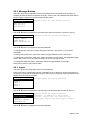
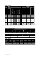
1
Manual
LifeLine Series
Installation, Programming
and Operation of
PX-100 Lifeline
Paging Control Panel
The operation and functions
described in this manual are
available from Software Version
Px100-001-01 onwards.
Item
Specification Details
Px-100
Enclosure
Steel IP30 RAL7035
Dimensions H x W
x D mm
288 x 348 x 78
Weight (excluding
batteries)
3.9Kg
Temperature
-5°C to 40°C
Humidity (RH)
95% Max
Cable Entries
(20mm knockouts)
6x top / 4x bottom / 1x rear
AC Supply
(ratings marked on
label inside panel
– see section 3.1
for location)
230V AC +/- 15%, xxA
Battery Capacity
2.6Ah (min) 7Ah (max)
Charging Current
0.35A nominal
Battery support
Up to 72 hours
(depending on battery and backlight mode)
Ripple (Vpkpk)
200mV max (Note: 1V p-p including switching frequency).
Max Battery
Resistance
1Ω +/1 0.1 Ω
Imax(a)/
Imax(b)
2.0A
2.0A
Supply Monitoring
Serial Data Communcations to main processor
Indicates AC condition, battery voltage, charger voltage, charging
current and temperature.
Display
Backlit 124 x 64 graphical LCD
LED Indicators
1 Green (Power), 1 Blue (Transmit & 3 Yellow (Fault & Status)
Keypad
Alpha Numeric Keypad, Navigation Keys
Controls
4 Programmable Function Buttons
Serial port
USB only
Transmitter
Frequency
459.15MHz, 25KHz channel separation
Transmitter power
Selectable in defined steps from 25mW to 2.0W
As our policy is one of constant product improvement the right is therefore reserved to modify product specifications without prior notice
Page 2 of 50
Table of Contents
1
Page
INTRODUCTION __________________________________________________________ 6
1.1
Standards ____________________________________________________________
1.2
Cautions and Warnings__________________________________________________
1.3
Description ___________________________________________________________
1.3.1
Px-100 Series _____________________________________________________
1.4
Installation Approvals ___________________________________________________
1.4.1
Fire System Installations _____________________________________________
1.4.2
Wiring Regulations__________________________________________________
1.4.3
Radio Licence _____________________________________________________
2
6
6
7
7
7
7
7
7
OPERATION _____________________________________________________________ 8
2.1
Controls and Indications _________________________________________________ 8
2.1.1
Graphical Display___________________________________________________ 8
2.1.2
LED Status Indicators _______________________________________________ 8
2.1.3
Function Buttons ___________________________________________________ 9
2.1.4
Navigation Buttons__________________________________________________ 9
2.1.5
Number and Letter Buttons ___________________________________________ 9
2.1.6
Buzzer ___________________________________________________________ 9
2.1.7
Key Switches _____________________________________________________ 10
2.2
Access Levels ________________________________________________________ 10
2.2.1
Changing Access Levels ____________________________________________ 10
2.2.2
Access Level 3 - Programming _______________________________________ 10
2.3
User Functions _______________________________________________________ 11
2.3.1
Level 1 Menu Options ______________________________________________ 13
2.3.1.1
2.3.1.2
2.3.1.3
2.3.2
2.3.2.1
2.3.2.2
2.3.2.3
2.3.2.4
2.3.2.5
3
Enable Controls_________________________________________________________ 13
View _________________________________________________________________ 13
LED TEST _____________________________________________________________ 14
Level 2 Menu Options ______________________________________________ 15
VIEW _________________________________________________________________
TEST _________________________________________________________________
OPERATING MODE _____________________________________________________
EXIT LEVEL-2__________________________________________________________
COMMISSION__________________________________________________________
INSTALLATION__________________________________________________________ 17
3.1
Identification of Parts __________________________________________________
3.2
Installing the Enclosure _________________________________________________
3.2.1
Opening the Enclosure Cover ________________________________________
3.2.2
Removing the Chassis ______________________________________________
3.2.3
Mounting the Enclosure _____________________________________________
3.2.4
Remounting the Chassis ____________________________________________
3.2.5
Recommended Cable Routing Arrangement _____________________________
3.3
Wiring Installation _____________________________________________________
3.3.1
AC Mains Wiring __________________________________________________
3.3.1.1
3.3.2
3.3.2.1
17
17
17
18
18
18
19
20
20
Cable Gland ___________________________________________________________ 20
Battery Installation _________________________________________________ 21
Battery Support _________________________________________________________ 21
3.3.3
Switch Inputs _____________________________________________________
3.3.4
Relay Outputs ____________________________________________________
3.3.5
RS232 Interface___________________________________________________
3.3.6
RS485 Interface___________________________________________________
3.3.7
USB Interface ____________________________________________________
3.3.8
Aerial ___________________________________________________________
3.4
Slide-In Labels _______________________________________________________
4
15
15
15
16
16
22
22
22
23
23
23
23
PROGRAMMING _________________________________________________________ 24
4.1
Introduction __________________________________________________________ 24
4.1.1
Access Levels ____________________________________________________ 24
4.1.2
Navigating through menus ___________________________________________ 24
Page 3 of 50
Changing Text Descriptions __________________________________________ 25
4.1.3
4.1.4
Numeric data entry _________________________________________________ 26
4.2
Level 3 Menu Functions ________________________________________________ 26
4.2.1
General Text _____________________________________________________ 26
4.2.2
Message Buttons __________________________________________________ 27
4.2.3
Inputs ___________________________________________________________ 27
4.2.3.1
4.2.3.2
4.2.3.3
4.2.3.4
4.2.3.5
4.2.3.6
4.2.4
Input Text ______________________________________________________________ 28
Action _________________________________________________________________ 29
Monitored ______________________________________________________________ 29
Type: _________________________________________________________________ 29
Pager Group: ___________________________________________________________ 29
Trigger SleepCom _______________________________________________________ 30
Outputs__________________________________________________________ 31
4.2.4.1
4.2.4.2
4.2.5
Mode _________________________________________________________________ 31
Inverted _______________________________________________________________ 32
Tools ___________________________________________________________ 32
4.2.5.1
4.2.5.2
4.2.5.3
4.2.6
4.2.7
Walk test_______________________________________________________________ 32
Send Test Message ______________________________________________________ 32
Transmitter Power _______________________________________________________ 32
Passwords _______________________________________________________ 33
General Parameters ________________________________________________ 33
4.2.7.1
4.2.7.2
4.2.7.3
4.2.7.4
4.2.7.5
4.2.7.6
4.2.7.7
4.2.7.8
4.2.7.9
4.2.7.10
4.2.8
4.2.9
4.2.10
Level 2 Time-Out ________________________________________________________ 33
Walk Test Delay _________________________________________________________ 34
1 Send Repeats _________________________________________________________ 34
Out of Range ___________________________________________________________ 34
Espa Address ___________________________________________________________ 34
Serial Comms___________________________________________________________ 34
Service Number _________________________________________________________ 34
Service Due ____________________________________________________________ 34
Config _________________________________________________________________ 34
Program _______________________________________________________________ 35
PC Link__________________________________________________________ 35
Exit _____________________________________________________________ 35
Pager Groups _____________________________________________________ 36
4.2.10.1 Inputs & Message Buttons and Pager Groups__________________________________ 36
4.2.10.2 Serial Messages and Pager Groups _________________________________________ 36
5
SERVICE AND MAINTENANCE _____________________________________________ 37
5.1
Maintenance Schedule _________________________________________________ 37
5.1.1
Daily Actions _____________________________________________________ 37
5.1.2
Monthly Actions ___________________________________________________ 37
5.1.3
Quarterly Actions __________________________________________________ 37
5.1.4
Annual Actions ____________________________________________________ 37
5.2
Replacement of Components ____________________________________________ 38
5.2.1
Liquid Crystal Display_______________________________________________ 38
5.2.2
Batteries _________________________________________________________ 38
5.2.2.1
Standby Batteries ________________________________________________________ 38
5.2.3
Spares __________________________________________________________ 39
5.3
Site Survey __________________________________________________________ 40
6
APPENDICES ___________________________________________________________ 41
6.1
Appendix 1 – Forgotten Level 3 Password __________________________________ 41
6.2
Appendix 2 – Recommended Fire Rated Cables _____________________________ 42
6.3
Appendix 3 – Site Configuration Record ____________________________________ 43
6.3.1
Site Pagers and Pager Group Allocation ________________________________ 43
6.3.2
Px-100 Configuration Record _________________________________________ 44
6.3.2.1
6.3.2.2
6.3.2.3
6.3.2.4
6.3.2.5
6.3.2.6
6.3.2.7
Page 4 of 50
Text Configuration _______________________________________________________ 44
Message Buttons ________________________________________________________ 45
Outputs________________________________________________________________ 45
Inputs _________________________________________________________________ 46
Transmitter Power _______________________________________________________ 46
Passwords _____________________________________________________________ 46
General________________________________________________________________ 46
Appendix 4 – Slide-In Template __________________________________________ 47
6.4
6.4.1
Approvals and Key-switch:___________________________________________ 47
6.4.2
Indicator and Buttons _______________________________________________ 47
Page 5 of 50
1 Introduction
1.1
Standards
Advanced Electronics Ltd declares that the product identified below conforms to the essential
requirements specified in the RTTE Directive 1999/5/EC:
On-site paging
EN 300 224-2 ERM On-Site Paging
EN 301 489-2 ERM EMC Radio Paging Equipment
Px-100
This product is of the Equipment Type “Class 2” (See Section 1.4.3).
It has been tested and complies with the harmonised standards listed above.
Furthermore, the product has been tested to and complies with the following standards:
Low Voltage Directive 2006/95/EC
EN60950-1: 2006
Safety of information technology equipment
Electromagnetic Compatibility Directive 2004/108/EC
EN55022: 1998
Emissions, Class B
EN50130-4: 1996 +A2: 2003
Immunity, Product Family Standard
In addition, the product is in conformity with the requirements of the following standard:
EN54-4: 1997 +A1:2002 +A2:2006
1.2
Power Supply Equipment
Cautions and Warnings
STOP
BEFORE INSTALLATION – Refer To the Ratings shown on the label inside
the product and to the ‘Specifications Chart’ in this document.
Please read this manual carefully. If you are unclear on any point DO NOT
proceed. Contact the manufacturer or supplier for clarification and guidance.
Only Trained service personnel should undertake the Installation,
Programming and Maintenance of this equipment.
This product has been designed to comply with the requirements of the Low
Voltage Safety and the EMC Directives. Failure to follow the installation
instructions may compromise its adherence to these standards.
ATTENTION
OBSERVE PRECAUTIONS
FOR HANDLING
ELECTROSTATIC
SENSITIVE DEVICES
Page 6 of 50
This equipment is constructed with static sensitive components. Observe antistatic precautions at all times when handling printed circuit boards. Wear an
anti-static earth strap connected to panel enclosure earth point. Before installing
or removing any printed circuit boards remove all sources of power (mains and
battery).
1.3
Description
This manual covers the installation, programming and operation of the Px-100 Series Paging
Control Panel. This manual provides generic programming, installation and operation information.
Refer to the User Manual (Document No. 680-191) for a quick guide to operation.
1.3.1 Px-100 Series
The LIFELINE Px-100 is a Control Panel for communication of alarm, fault, test and other
conditions to hand held or fixed paging receivers for the purpose of communicating those
conditions to persons with deafness or hard of hearing.
Install the panel in accordance with the instructions in Section 3 and then program the
operation in accordance with the instructions detailed in Section 4.
The basic operation is indicated in Section 2 and is fully detailed in User Manual 680-191.
1.4
Installation Approvals
1.4.1 Fire System Installations
The panel must be installed and configured for operation in accordance with these instructions
and the applicable code of practice or national standard regulations for fire systems installation
(for example BS5839-1: 2002) appropriate to the country and location of the installation.
1.4.2 Wiring Regulations
The panel and system must be installed in accordance with these instructions and the applicable
wiring codes and regulations (for example BS7671) appropriate to the country and location of the
installation.
1.4.3 Radio Licence
Use of this equipment requires this issuance of an “Individual Site Licence” by the national body
responsible for frequency allocation and use.
Page 7 of 50
2 Operation
Display
Navigation Buttons
Li fe Line
ABC
DEF
GHI
JKL
MNO
PQRS
TUV
WXYZ
ESC
Status Indicators
MENU
Function Buttons
Number Buttons
2.1 Controls and Indications
2.1.1 Graphical Display
The graphical display provides detailed information on current operational condition, any fault
condition and provides a menu function for configuration.
The normal (quiescent) display is shown
opposite. The display will show events and
other information as required.
The logo may be different and show the
installer / maintenance company logo.
SYSTEM NORMAL
2.1.2 LED Status Indicators
The LED Status Indications show the basic operational state of the panel and whether the panel
is in a fire alarm, fault, disabled or test condition.
Function
Colour
Description
Power
Green
Indicates the presence of power
Transmit
Blue
Indicates that a transmission is in progress – illuminates when a
transmission occurs
Fault
Yellow
Indicates that the system has detected a fault condition
System Fault
Yellow
Indicates the presence of a system fault
Commission
Yellow
Indicates that the panel is in a programming / service condition
Page 8 of 50
2.1.3 Function Buttons
The following table contains a list of all of the control button functions available.
Button
Description
Access Level
Function Button
Programmable message function – the function will
be identified on slide-in label text.
Press to send the programmed message.
Level-1 or Level-2
Depends on
Programming
2.1.4 Navigation Buttons
ÍÏÐÎ
Press to scroll through Menu Options.
Press to display more information.
Press to scroll through the text of sent messages.
Press to confirm entry of numeric or letter information entry.
Press to confirm selection of a menu option.
Press to change some of the configuration options.
Press to mute the buzzer.
2.1.5 Number and Letter Buttons
ABC
D EF
GHI
J KL
MN O
P Q RS
TUV
WXYZ
ESC
Used to enter numbers or letters.
MENU
Esc
Press to return to a previous menu.
Press to exit the menu functions and return to the normal display.
Menu
Press to show or return to Menu Functions.
2.1.6 Buzzer
The buzzer sounds to indicate fault conditions.
Condition
Operation
Fault
The buzzer operates intermittently.
Page 9 of 50
2.1.7 Key Switches
The key switches are used to enable access to the system and to configure the system to
operating modes.
Switch
Operation
KEY
ACCESS
(Controls)
2-Position: Enables user controls and Level-2 access – key is
trapped in the enable position.
L003
MODE
(Engineer)
3-Position: Enables test and engineer modes in addition to
the normal “Operate” mode.
CAT30
2.2
Access Levels
The panel operation is protected from inadvertent and erroneous misuse by means of four access
levels. These levels are as follows:
Level 1
Level 2
Level 3
Level 4
•
Untrained user
Authorised Users
Service and Maintenance Engineer
Service and Maintenance Engineer – Special Tools required
A Level 1 Untrained User can view the current operational condition of the system and may
MUTE the internal buzzer.
NOTE: Depending on the configuration settings, a Level 1 user may also be permitted to operate the
CONTROL buttons by pressing the appropriate button and entering a password.
•
A Level 2 Authorised User can view the operational condition of the system and may MUTE
the internal buzzer. In addition, the CONTROL buttons are enabled and access to the Level 2
Menu functions is available.
NOTE: There are up to 4 User ID codes available, each with its own password, which can be
configured.
•
A Level 3 User has access to program and configure the operation of the panel. This is
described in detail in Section 4.
2.2.1 Changing Access Levels
The main user controls and Level-2 operation are normally enabled by means of the controls keyswitch.
Insert key and turn to the enable position to enable controls.
The key cannot be removed in this condition. Turn the key back to disable controls and remove
the key.
Alternatively, they can be enabled by means of a password.
Press the MENU button and the display will prompt for the Level 2 password. Enter the password
using the number buttons and then press the button. The Level 2 menu will now be shown.
To cancel Level 2 access, select the menu function EXIT LEVEL-2. The controls will then be
disabled the display will revert to the normal display. The panel can also be configured to
automatically cancel Level-2 access after a preset time of no activity (default 5 minutes).
2.2.2 Access Level 3 - Programming
Access Level 3 can only be reached by first enabling the Level-2 controls.
Use the ÏÐ buttons to select the COMMISSION menu option and press the button. The
display will prompt for the Level 3 password.
For further information, refer to the programming section.
Page 10 of 50
2.3 User Functions
Operating Modes – The panel has three basic operating modes selected by the position of the
front panel key-switch (or by menu option).
Normal Mode
SYSTEM NORMAL
The normal (quiescent) display is shown
opposite. The display will show events and
other information as required.
The logo may be different and show the
installer / maintenance company logo.
Messages will be automatically transmitted to the pagers when the connected fire alarm control
panel activates into fire, fault, pre-alarm or warning conditions (as programmed).
The panel will automatically transmit a confidence message every 60s (if configured). This is used
by the pagers to detect if they remain within range of the transmitter. If the pagers do not receive
this message for 120s then they will vibrate and indicate an out of range condition.
Test Mode
SYSTEM NORMAL
SYSTEM IN TEST MODE
If the operating switch is set to test mode,
the display will show this condition.
All paging messages will be prefixed by the
word TEST (or alternative configured text)to
indicate that the message is a test only
message.
Engineer Mode
SYSTEM NORMAL
ENGINEERING MODE ON
If the operating switch is set to engineer
mode, the display will show this condition.
All paging messages will now only be sent to
the special “engineers” pager.
Not to other pagers.
All other pagers will not receive messages!
Ensure that other measures are in place to alert occupants should a fire alarm occur.
Page 11 of 50
Fault Conditions
[System Status]
1 of 1 conditions:
INPUT 8
OPEN CIRCUIT
LAST MESSAGE SENT…
FAULT >INPUT 8 >OPEN
If the panel detects a fault condition, the
details are shown on the display. The Fault
LED will flash.
As with all transmissions, the display will
also show the text of the last transmitted
message for 30 sec after the last key press.
The first fault condition is shown along with the number of fault conditions present.
If there is more than one fault condition present, use the ÏÐ buttons to scroll through the list of
fault conditions. For example:
[System Status]
2 of 3 conditions:
MAINS SUPPLY
MISSING
LAST MESSAGE SENT…
FAULT >INPUT 8 >OPEN
If there is more text in the last message sent than can fit on the display, use the ÍÎ
buttons to scroll through the remainder of the text message.
NOTE: If the AC Mains supply fails, the display will indicate this fault condition and will turn off the
display backlight to extend the battery support time.
Pressing any of the navigation keys will reactivate the backlight for 30 seconds.
Manual Message
The function buttons allow a pre-programmed message to be transmitted to one or more pagers.
If required, insert and turn the “Access Enable” key.
Press the required Message Button.
The pre-programmed message will be sent and the blue transmit indicator will illuminate as the
message is sent.
Page 12 of 50
2.3.1 Level 1 Menu Options
Press the MENU button.
[Level 1 Menu]
ENABLE CONTROLS
VIEW
LED TEST
The Level 1 menu shows three options.
Use the ÏÐ buttons to select the required option. Press the button to select.
2.3.1.1 Enable Controls
Enable controls is normally activated using the front panel key-switch.
Disable Enable
Insert the key and turn clockwise to enable controls.
The key can only be removed in the disable position.
Alternatively, to use a password, select the Enable Controls menu option and then press the button. The display shows:
Enter your password
**
Enter the password using the number buttons
and then press the button to confirm.
Each number button press is indicated by a
‘*’ character.
Enter the password using the number buttons and press the button. If the password is not
entered quickly enough or is not recognised, the display shows:
Enter your password
Not recognised!
The display will revert back to the Level 1
Menu after a few seconds.
When controls are enabled, the display will show the Level 2 Menu options.
2.3.1.2 View
[View Menu]
FAULTS
PANEL
SW VERSIONS
The Level 1 view menu shows three options.
FAULTS:
The display will show any faults currently registered.
[Fault Status]
1 of 1
INPUT 8
>OPEN CIRCUIT
Page 13 of 50
If there is more than one fault condition present, use the ÏÐ buttons to scroll through the list of
fault conditions.
PANEL:
The display will show the internal operating conditions for the system power.
[Panel Levels]
SYSTEM VOLTS 13.31V
BATTERY (V)
13.52V
CHARGER (V)
13.94V
CHARGER (I)
322mA
TEMPERATURE
25deg
In addition to the parameters opposite, the
transmitter current is available. This is
shown in milliamps.
Use the ÏÐ buttons to scroll through the readings.
Press ESC to return to the previous menu.
SW VERSIONS:
The display will show the versions of software programme into the main processor and the power
supply processor
[Software Versions]
PANEL
: 01.00
P.S.U.
: 03.00
Press ESC to return to the previous menu.
2.3.1.3 LED TEST
Select the LED test option. Press the button to select.
The LED indicators will illuminate for five (5) seconds and then revert to the previous indication.
Page 14 of 50
2.3.2 Level 2 Menu Options
[Level 2 Menu]
VIEW
TEST
OPERATING MODE
EXIT LEVEL-2
COMMISSION
The Level 2 menu shows five options.
Use the ÏÐ buttons to select the required option. Press the button to select.
2.3.2.1 VIEW
This menu is identical to the view menu available at Level-1.
2.3.2.2 TEST
This option will test the operation of user control buttons and indicators.
[Test Menu]
DISPLAY
BUZZER
The Test menu shows two options.
Use the ÏÐ buttons to select the required option. Press the button to select.
DISPLAY:
This is similar to the Level-1 menu, but the display option will test both the indications on the LED
indicators and those on the LCD.
In addition, it is possible to test the operation of each of the front panel buttons.
Press ESC to return to the previous menu.
BUZZER:
This option will activate the internal buzzer for five (5) seconds.
2.3.2.3 OPERATING MODE
Operate
Test
Engineer This function is normally activated using the front panel key-switch. Insert the
key and turn anti-clockwise or clockwise to select the test or engineers mode
as required.
The key can only be removed in the normal operating mode.
Alternatively, to enable from the menu, use the ÏÐ buttons to select the operating mode menu
option and then press the button to select.
[System Mode]
NORMAL OPERATION
TEST MODE
ENGINEERS MODE
The Test menu shows three options.
Use the ÏÐ buttons to select the required operating mode menu option and then press the button to select.
NOTE: The panel will remain in the mode selected. Remember to select and revert to the normal
operating mode when testing or engineer functions are completed.
Page 15 of 50
2.3.2.4 EXIT LEVEL-2
Select this option to cancel Level-2 and revert to Level-1
2.3.2.5 COMMISSION
Select this option to enable Level-3 programming functions. Refer to programming section.
Page 16 of 50
3 Installation
3.1
Identification of Parts
The following diagram shows the major parts of the panel.
The Px-100 comprises of a back box, chassis plate electronic assembly, aerial assembly and a cover.
The chassis plate is fixed to the back box with two screws.
The cover is fixed to the back box with two hex (Allen) key screws.
The cover earth lead must be connected to the spade terminal in the back box.
AERIAL
RATINGS
HB-PSU
Life Line
HB-Panel
TX
RX
CHASSIS FIXING
SCREWS X2
REBOOT
ABC
DEF
GHI
JKL
M NO
PQRS
T UV
ESC
USB
WXY Z
ME NU
JUMPE R
RS2 32
R S 485
FLT RLY
RLY -1
RLY- 2
RLY -3
INPUT- 1 INPUT -2 INPUT- 3 INP UT-4
INPUT -5 INP UT- 6 INPUT-7 I NP UT- 8
BAT TERY
BA TT ERY
F US E
ST ART
F ROM
B AT TE RY
J1
RUN PRO G
uP M ODE
COVER FIXING
SCREWS X2
CHASSIS
ASSEMBLY
EARTH LEAD
EARTH LEAD
CHASSIS TO BACK BOX
COVER TO BACK BOX
BACK BOX
COVER
3.2 Installing the Enclosure
Use the appropriate fixing hardware to secure the panel to the wall. See table below for
maximum weights.
Enclosure
Px-100
Weight
3.9kg
Maximum Battery
7Ah
Overall Maximum Weight
5kg
3.2.1 Opening the Enclosure Cover
The enclosure covers of the Px-100 is fixed with two screws – use the supplied Allen key. Detach
the earth lead from the back box to completely remove. Place the cover in a safe place to prevent
accidental damage and retain the fixing screws.
Page 17 of 50
3.2.2 Removing the Chassis
It is recommended that the chassis be removed before fitting the panel to the wall. To remove the
chassis:
Disconnect the earth cable connecting the chassis to the spade terminal on the rear enclosure.
Remove the two screws holding the chassis to the back box and carefully remove the chassis
from the rear enclosure. Before the chassis can be fully removed, unplug the AC Mains Cable and
Transmitter Aerial cable from the PCB. Place the chassis in a safe place to prevent accidental
damage and retain the fixing screws.
DO NOT lift the chassis by holding onto any of the printed circuit cards. Hold the chassis by
the metal plate only.
DO NOT dismantle the chassis assembly or remove the cover for the PSU area.
WARNING – HIGH VOLTAGE.
The transmitter module is an inherent part of the chassis assembly. DO NOT remove.
3.2.3 Mounting the Enclosure
Firstly, remove the required knockouts for
the installation wiring. There are six
knockouts on the top of the enclosure that
will suit all normal installation wiring.
Alternatively, there are four additional
knockouts at the bottom of the enclosure for
signal wiring. A single knockout is provided
in the rear wall for rear entry cabling of the
AC Mains power, if required.
AERIAL
The enclosure is provided with three fixing
points.
The diagram opposite shows the positions
of the three holes and dimensions of each
enclosure. Use all three positions to ensure
the panel is held securely to the wall.
Drill the required holes in the supporting wall
using a drill bit diameter 7.0 mm and plug
with a suitable 40mm or longer expansion
plugs. Affix the panel to the wall with M5
screws or No.10 screws. Use appropriate
fixings to support the weight including the
batteries.
CABLE TIE ANCHOR
POINTS
ALTERNATIVE AC FEED
ENTRY KNOCKOUT
Ensure that there is sufficient space to allow
the door to be opened when the panel is
mounted.
Finally, use a brush to remove any dust or
swarf from inside the enclosure.
Px-100 Enclosure Size and Fixing Point Dimensions
3.2.4 Remounting the Chassis
Carefully replace the chassis and fix into place using the two screws.
Reconnect the chassis earth cable to the spade terminal in the rear of the enclosure.
Page 18 of 50
3.2.5 Recommended Cable Routing Arrangement
It is recommended that the
typical routing arrangement
shown in the diagrams
opposite be employed.
Segregate the low voltage
wiring (DC Power and Field
Wiring) from any AC Mains
Wiring.
AC MAINS
Alternative
entry in back
of box
INPUT / OUTPUT SIGNALS
HB-PSU
LifeLine
HB- Panel
TX
Refer to Appendix 2 –
Recommended Fire Rated
Cables for further information
on cable types to be used.
If using the top knockouts –
Tie-wrap the data cables to
the back of the enclosure
using the anchor points
provided
If using the bottom
knockouts – Ensure the data
wires are routed to the left of
the battery so that they do
not foul with the battery
retaining bracket on the
cover.
RX
REBOOT
ABC
DEF
G HI
J KL
MNO
PQ RS
TUV
ESC
USB
RS23 2
RS4 85
F LT RLY
RLY- 1
RLY-2
RLY- 3
INPUT -1 INPUT- 2 INPUT-3 I NPUT -4 INPUT- 5 INPUT-6 I NPUT- 7 INPUT-8
BATT ERY
WXYZ
MENU
BAT TERY
FUSE
START
FRO M
BATT ERY
JUM PER
J1
R UN P ROG
uP MO DE
BATTERY
DATA WIRES
Use top or bottom
knockouts as required
INPUT / OUTPUT SIGNALS
Internal arrangement showing recommended routing of cables.
AC FEED
The AC Feed cable and the
aerial cable are connected to
the reverse of the chassis
directly onto the PCB.
The diagram opposite shows
the connector positions.
Remember that there is a
separate earth lead
connecting the chassis plate
to the back box. Ensure that
the spade terminal is
plugged onto the blade
connector on the rear wall of
the enclosure.
Aerial
Page 19 of 50
3.3
Wiring Installation
All electrical wiring installation work should be carried out in accordance with the code of practice
or applicable national standards appropriate to the country of installation.
To maintain electrical integrity of the SELV wiring on the DC Power and communications lines all
SELV wiring should be segregated from the LV mains wiring and be wired using cable with
insulation suitable for the application.
To minimise the effects of EMC interference all data wiring circuits should be wired with a twisted
pair of conductors with a cross sectional area suitable for the loading conditions.
In areas where cabling may come into contact with high frequency interference, such as portable
radio transceivers etc. the data wiring cable should be of a twisted pair construction within an
overall screen. Care should be taken to correctly terminate this screen, refer to the appropriate
sections of this manual for further information for each circuit type.
3.3.1 AC Mains Wiring
Route the high voltage mains AC wiring into the
enclosure at the upper right corner only. Keep the
AC wiring away from the circuit boards and all
other wiring.
Panel Wiring
FUSE
Brown
3.15A
LIVE
Green
EARTH
The panels must be connected to
the supply earth through the power
cable.
Must be
earthed
The mains input connector is shown in the
diagram opposite. Note the positions of the earth,
neutral and live terminal connections. These are
clearly marked on the label next to the connector.
The connector block contains an integral fuse
holder.
Secure the mains input wiring by tie wrap as close
to the terminal block as possible – cable tie
anchor points are provided.
NEUTRAL
Blue
AC Mains terminations
The fuse is rated as follows:
T 3.15A H 250V
Replace with correct rating and specification only.
Cable size: 12-22AWG (0.5mm2-4.0mm2).
Connect the Control Panel to the mains supply via
a readily accessible disconnect-device (Isolation
Switch) and suitable earth fault protection
incorporated in the building installation wiring. The
Mains cable should be 0.75mm2 cable rated at
250V and fused via a 5A anti-surge fuse.
3.3.1.1
Cable Gland
The cable gland and any cord clamp bushings used in routing the Mains cable through the
20mm knockout must have a minimum flame-retardant rating of 94HB.
Suggested glands and bushings are: Type
Manufacturer
Gland IP65 – Brass M20, EExd / Eexe
Lappcable
Gland IP68 – Nylon 66 M20 Black, UL94V2
Multicomp
Bushing – Nylon 66 M20 Black, UL94V2
Multipcomp
Page 20 of 50
3.3.2 Battery Installation
The panel requires a single 12V
battery for standby operation.
The battery leads are connected
onto the base card via a plug, as
shown in the diagram opposite.
Refer to the Specifications for
minimum and maximum battery
sizes allowed.
HB-PSU
LifeLine
HB- Panel
TX
RX
OBSERVE POLARITY OF
CONNECTIONS!
REBOOT
Once correctly wired, the terminal
block plug is arranged so that no
damage will occur if it is plugged in
back to front.
ABC
DEF
G HI
J KL
MNO
PQ RS
TUV
ESC
USB
RS23 2
Slide the battery to the right. There
is a bracket on the cover that acts
as a battery retaining strap to avoid
movement of the battery in the
installation.
RS4 85
F LT RLY
RLY- 1
RLY-2
RLY- 3
INPUT -1 INPUT- 2 INPUT-3 I NPUT -4 INPUT- 5 INPUT-6 I NPUT- 7 INPUT-8
BATT ERY
WXYZ
MENU
BAT TERY
FUSE
START
FRO M
BATT ERY
JUM PER
J1
R UN P ROG
uP MO DE
BATTERY LEADS
BATTERY up to 7Ah
Slide battery to the right. A
restraining bracket is provided
as part of the cover to prevent
movement of the battery.
Battery Terminations
Place the battery in the bottom of the enclosure
and connect the ‘Red’ lead to the positive (+)
terminal of battery and the ‘Black’ lead to the
negative (-) terminal of the battery.
Ensure that the battery terminals do not short out
against any part of the enclosure, circuit board or
chassis plate.
2
NC
BLACK
+
RED
+
-
2
Cable size: 24-14AWG (0.3mm -2.5mm ).
3.3.2.1 Battery Support
The following table shows the battery sizes required to support 24, 48 or 72 hours battery support
in accordance with the recommendations in BS5839-1:2002.
The table covers different backlight operating modes and is applicable for all transmitter power
settings.
Hours
Battery
Capacity
24
2.6Ah
48
7Ah
72
7Ah
Page 21 of 50
3.3.3 Switch Inputs
+
–
6K8
The negative connection is connected to chassis
ground (earth).
INPUTS
Volt-free
Monitored for open,
short and active –
6K8 EOL
Activation resistor –
470R
470R
Eight programmable switch inputs are provided
and can be configured to activate predefined
messages. Each input is (optionally) monitored for
short and open circuits and for activation.
A 6K8 EOL resistor must be fitted across the
terminals if the input is unused.
Maximum circuit impedance 50 ohms.
Cable size: 28-16AWG (0.1mm2-1.5mm2).
Refer to programming section on how to configure
these inputs.
The optional EXP-005 module provides a
convenient method of terminating the line with the
correct resistor values.
3.3.4 Relay Outputs
All relay outputs are rated at 30V AC/DC, 1.0A,
resistive.
Cable size: 28-16AWG (0.1mm2-1.5mm2).
One dedicated relay (FLT RLY) is provided for
fault indication. This is a changeover type relay
configured for “Fail-Safe” operation. It is normally
energised and will de-energise under any fault
condition included total power failure.
FAULT RELAY
NO
“Fail-Safe” Operation
The relay will deenergize on any fault
condition. The deenergized state is
shown
NC
COM
PROG RELAYS
NO
RLY-1, RLY-2, RLY-3
Relays energize on
the programmed
condition.
Three programmable relays are also provided.
These are normally de-energised and will activate
on the programmed condition.
COM
Refer to programming section on how to configure
these outputs.
3.3.5 RS232 Interface
The RS232 Interface uses common signals with
the RS485 Interface. Only one of these interfaces
can be used.
RLY-2
RLY-1
FLT RLY
RS485
TX = Transmit Data from the panel, RX = Receive
Data into the panel, GND = Ground Reference.
TX
RX
GND
A
B
The terminal block connections are shown
opposite.
RS232
The Px-100 is equipped with an RS232 I/F Circuit
at the bottom of the base card.
Connect TX output to panel RX input
Connect RX input to panel TX output
Connect GND to panel GND
Cable size: 28-16AWG (0.1mm2-1.5mm2).
This interface can be used for serial connection to
the Mx range of fire alarm control systems offered
by Advanced Electronics Ltd.
Page 22 of 50
Base Card Connections.
The RS485 Interface uses common signals with
the RS232 Interface. Only one of these interfaces
can be used.
RLY-2
RLY-1
FLT RLY
RS232
The terminal block connections are shown
opposite.
TX
RX
GND
A
B
The Px-100 is equipped with an RS485 I/F Circuit
at the bottom of the base card.
RS485
3.3.6 RS485 Interface
Connect A to panel A
Connect B to panel B
Cable size: 28-16AWG (0.1mm2-1.5mm2).
This interface can be used for serial connection to
the Mx range of fire alarm control systems offered
by Advanced Electronics Ltd.
Base Card Connections.
3.3.7 USB Interface
The Px-100 is equipped with a USB I/F Circuit.
This can be used for connection to a PC for use with the PC Tools.
3.3.8 Aerial
The aerial is a ¼-wave antenna.
To prevent erroneous or inadvertent removal, the
aerial can only be removed from inside the panel.
The aerial is attached to the bulkhead connector
on the mounting plate. The mounting plate is fixed
to pillars inside the back box using 4x M3 screws.
The aerial is connected to the printed circuit card
chassis by means of a separate coax screened
cable.
To remove / replace the aerial, remove the four
M3 fixing screws. Unscrew the aerial from the
connector.
M3 Screws
3.4 Slide-In Labels
The function of the message buttons can be customised (see Programming Section). To
complement this, the functions assigned to the buttons can be adjusted and a new slide-in label
can be inserted behind the fascia label to customise the panel. A sample template is included in
Appendix 4.
Refer to the www.advel.co.uk to download a copy of the template in an editable format.
Page 23 of 50
4 Programming
4.1
Introduction
4.1.1 Access Levels
The panel operation is protected from inadvertent and erroneous misuse by means of four access
levels. These levels are as follows:
Level 1 Untrained user
Level 2 Authorised User
Level 3 Commissioning, Service and Maintenance
Level 4 Commissioning, Service and Maintenance – Special Tools Required
This document covers the Level 3 functions. For details on the operation and use of the panel at
Levels 1 & 2, refer to User Manual 680-166. Full details are supplied with the special tools.
A level-3 password is required to enter the commissioning menus. For details of Passwords, refer
to Section 4.2.6.
Level-3 Passwords.
If this number is lost, it is not possible to enter commission mode functions.
Refer to section 6.1 for further formation.
Default
7654
4.1.2 Navigating through menus
The display will revert to status mode after 60s. Press the ‘Menu’ button to restore the display.
[Level 3 Menu]
GENERAL TEXT
MESSAGE BUTTONS
INPUTS
OUTPUTS
TOOLS
When a menu is displayed, use the ÏÐ buttons to highlight the required menu option and then
press the button to select it.
Press the ‘Esc’ button from within a menu option to return to the previous menu.
The display can be forced back into status mode by pressing the ‘Esc’ button when at the top
level commissioning menu (or by waiting 60s).
Page 24 of 50
4.1.3 Changing Text Descriptions
Various parameters can have a text description defined.
To change the text description, first highlight the text description within the appropriate
programming option and then press the button. The display then changes to show the text
entry dialogue screen. For example:
KEY IN TEXT
1
>ADVANCED SITE 2
2abc 3 def
4 ghi 5 jkl 6 mno
<
7pqrs 8 tuv 9wxyz
The method of entering the characters is similar to the method employed
on mobile telephones. The number buttons provide both their
appropriate number and several letters of the alphabet. An example of
the keypad is shown opposite.
Esc
09
Menu
For example, Button 2 allows entry of the number 2 and letters A, B and C.
When a button is pressed, the first character is shown on the display at the current cursor
position. If the button is pressed again within ½ second, the second character replaces the first. A
further press displays the third available character and so on – see table below. After pressing the
button to obtain the required character, wait for 1-second and the character will be entered and
the cursor will move to the next character in the text description.
Pressing another button will immediately enter the previous character and move the cursor on to
the next character.
Use the ÍÎ buttons to move backwards or forwards along the line. When the text description is
as required, press the button to confirm the change.
If the text has been entered incorrectly, press the ‘Esc’ button to cancel all changes and return to
the previous display.
The following table shows the numbers, characters and symbols assigned to each button on the
keypad.
st
Button
1 Press
1
1
nd
2 Press
rd
th
3 Press
4 Press
2
A
B
C
2
3
D
E
F
3
4
G
H
I
4
5
J
K
L
5
6
M
N
O
6
7
P
Q
R
S
8
T
U
V
8
9
W
X
Y
Z
0
Blank
0
th
5 Press
7
9
Alternatively, press the ÏÐ buttons to scroll through a list of characters. When the required
character is shown, press the Î button to move on to the next character. The list of characters
available and the order of presentation is as follows:
Blank !“#$%&‘()*+,-./ 0123456789 :;<=>?@ ABCDEFGHIJKLMNOPQRSTUVWXYZ
[\]^_`abcdefghijklmnopqrstuvwxyz
Page 25 of 50
4.1.4 Numeric data entry
Numbers are entered by moving to the required field, and then typing in the required number,
followed by the button.
If the number is entered incorrectly, press the ‘Esc’ button to restore the previous number.
4.2
Level 3 Menu Functions
The following table gives a list of the Level 3 Menu Functions, the sub-functions available within
each main function and a brief description for each function.
Main Menu Option
Comments
GENERAL TEXT
Configure panel name and general text items
MESSAGE BUTTONS
Configure the message to be transmitted when the button is pressed and at
which access level the button is enabled
INPUTS
Configure the message to be transmitted when the input is activated and
configure the input circuit parameters
OUTPUTS
Configure the function of the relay outputs
TOOLS
Configure the transmitter power level and perform site tests.
PASSWORDS
Configure the user and engineer passwords
GENERAL
Configure general operating parameters
ENABLE P.C. LINK
Enable the USB PC Link for configuration purposes
EXIT
Exit from Level 3
4.2.1 General Text
This option enables the name of the panel and the leading text headers for test and fault to be
configured.
Each text string can be up to 40 characters long. However, for the test and fault leaders, it is
recommended to keep these at no more than five characters so that the messages on the pager
display are kept short.
[General Text]
PANEL NAME:
ADVANCED SITE 2
TEST TEXT: TEST
FAULT TEXT: FAULT
The menu shows three configurable items.
Use the ÏÐ buttons to highlight the required text item and then press the button to select it.
Enter the required text – refer to section 4.1.3 for full details of how to change text.
Page 26 of 50
4.2.2 Message Buttons
This menu allows the configuration of the text message to be transmitted when the button is
pressed, whether the button is operative at Level-1 and/or Level-2 and whether this button will be
used to trigger a SleepCom unit associated with the system.
[Message Buttons]
Mesg Button 1
Mesg Button 2
Mesg Button 3
Mesg Button 4
The menu shows the four message buttons.
Use the ÏÐ buttons to highlight the required button and then press the button to select it.
[Message Button-1]
INPUT TEXT: BUTTON-1
ACCESS: LEVEL-1
PAGER GROUP: 1
TRIG’ SLEEPCOM: NO
The menu shows the available parameters.
Use the ÏÐ buttons to highlight the required parameter.
To change the text, press the button and amend the text – see section 4.1.3 for further
information.
To change the access level, press the button to toggle between Level-1 and Level-2.
To change the access level, press the button and enter a numeric value, the designated Pager
Group. See section 4.2.10 for more information on the use of Pager Groups.
To change the Sleepcom option, press the button to toggle between Yes and No.
Press ESC to return to the previous menu.
4.2.3 Inputs
This menu allows the configuration input circuit parameters.
Each circuit can be configured to transmit a message (once or repeat) or can be configured as a
control input. If the input is assigned to transmit, the input text configured will be transmitted to the
pagers when this input is activated.
[Inputs]
INPUT 1
INPUT 2
INPUT 3
INPUT 4
INPUT 5
↓
The menu shows the inputs available.
Use the ÏÐ buttons to highlight the required input and then press the button to select it.
[Input-1 Settings]
INPUT TEXT:
FIRE EVACUATE
ACTION:
TRANSMIT -REPEAT
MONITORED: NO
The menu shows the input parameters
available. In addition to those shown
opposite, options are also available for
Input Type, Pager Group and Trigger SleepCom.
Use the ÏÐ buttons to highlight the required parameter.
Page 27 of 50
4.2.3.1 Input Text
To change the text, press the button and amend the text – see section 4.1.3 for further
information.
Note: The text is only relevant when either of the ‘Transmit’ actions are configured.
Page 28 of 50
4.2.3.2 Action
To change the action, press the button and a further menu with options is shown.
[Input Action]
NOT IN USE
TRANSMIT –ONCE
TRANSMIT – REPEAT
TEST MODE
TEST OVERRIDE
↓
The menu shows the input actions available.
The following input actions are possible:
Action
Function
NOT IN USE
This input is not used
TRANSMIT – ONCE
Activation of this input will result in the input text defined for this input being sent once
(or the minimum number of sends allowed – see section 4.2.7 for details).
TRANSMIT – REPEAT
Activation of this input will result in the input text defined for this input being sent
continuously while ever the input remains active, with an interval of 10 seconds.
TEST MODE
Activation of this input will place the panel into TEST mode (alternative method to the
key-switch and menu functions). Note: ENGINEER mode overrides TEST mode.
TEST OVERRIDE
Activation of this input will cause any active test-mode to be cancelled. This is
intended to cover a situation where a real fire occurs whilst part of the system is
undergoing testing.
GENERAL FAULT
Activation of this input will place the panel into a fault condition.
LEVEL-2 ACCESS
Activation of this input will enable Level-2 control and menu functions (alternative
method to the key-switch and menu functions). All such inputs (and key-switch) must
be inactive in order to cancel level-2 access.
ENGINEER MODE
Activation of this input will place the panel into ENGINEER mode (alternative method
to the key-switch and menu functions). Note: ENGINEER mode overrides TEST
mode.
WALK TEST
Activates a special sequence which transmits a test message repeatedly (time
interval dependant on configuration) to allow a one-man walk test of the building to
assist in ascertaining reception coverage.
4.2.3.3 Monitored
The switch wiring can be set to monitored (Yes) or not monitored (No).
When set to monitored, the panel will check the wiring for normal, open circuit, short circuit and
active conditions.
When set to not monitored, the panel will check for normal and activation only.
To change the monitored parameter, press the button to toggle between YES and NO.
4.2.3.4 Type:
The normal input condition can be changed to suit the type of switch connected.
To change the type parameter, press the button to toggle between NORMALLY OPEN and
NORMALLY CLOSED.
The default setting is normally open.
4.2.3.5 Pager Group:
The Pager Group setting determines which pagers in use on site the message will be sent to. The
number of pager groups actually available will be dependant on the pagers and there group
settings ordered with the system.
To change the access level, press the button and enter a numeric value, the designated Pager
Group.
The default setting is 1. See section 4.2.10 for more information on the use of Pager Groups.
Note: This parameter is only relevant when either of the ‘Transmit’ actions are configured.
Page 29 of 50
4.2.3.6 Trigger SleepCom
The “Trig’ SleepCom” option is used to denote whether this input will be used to trigger a
SleepCom unit associated with the system.
To change the monitored parameter, press the button to toggle between YES and NO.
The default setting is YES.
Note: This parameter is only relevant when either of the ‘Transmit’ actions are configured.
Page 30 of 50
4.2.4 Outputs
This menu allows the outputs to be configured.
[Prog. Outputs]
RELAY 1:
ANY INPUT ON
RELAY 2:
GENERAL FAULT
RELAY 3:
The menu shows the output modes available.
Use the ÏÐ buttons to highlight the required output and then press the button to select it.
[Output Settings]
MODE: TEST MODE
INVERTED: NO
The menu shows the output settings available.
Use the ÏÐ buttons to highlight the required parameter and then press the button to select it.
4.2.4.1 Mode
There are several possible cause and effects options that can be configured to turn the relay on.
[Output Modes]
NOT IN USE
GENERAL FAULT
TEST MODE
ENGINEER MODE
The menu shows the output modes available.
Use the ÏÐ buttons to highlight the required mode and then press the button to select it.
The following output modes are possible:
Mode
Function
NOT IN USE
This output is not used
GENERAL FAULT
The output will activate and remain active while ever a fault condition is present.
TEST MODE
The output will activate and remain active while ever the test mode is operational.
ENGINEER MODE
The output will activate and remain active while ever the engineer mode is
operational.
ANY INPUT ACTIVE
The output will activate and remain active while ever any of the 8 inputs is active. This
can be used as a general acknowledgement that a signal has activated an input.
INPUT-1 ACTIVE
The output will activate and remain active while ever input-1 is active. This can be
used as a specific acknowledgement that input-1 has been registered by the panel as
active.
INPUT-2 ACTIVE
The output will activate and remain active while ever input-2 is active. This can be
used as a specific acknowledgement that input-2 has been registered by the panel as
active.
INPUT-3 ACTIVE
The output will activate and remain active while ever input-3 is active. This can be
used as a specific acknowledgement that input-3 has been registered by the panel as
active.
Page 31 of 50
4.2.4.2 Inverted
The output can be changed from normal (NO, normally open, closed on activation) to inverted
(YES, closed, open on activation).
To change the inverted parameter, press the button to toggle between YES and NO.
4.2.5 Tools
This menu allows the basic transmitter functionality to be tested and configured.
[Tools Menu]
WALK TEST
SEND TEST MESSAGE
TRANSMITTER POWER
The menu shows the options available for
testing and configuring the transmitter.
4.2.5.1 Walk test
This menu allows a walk-test to be controlled from the level-3 menu.
Activates a special sequence which transmits a test message repeatedly (time interval dependant
on configuration) to allow a one-man walk test of the building to assist in ascertaining reception
coverage. While running a message is repeatedly transmitted which contains numeric value
incremented on each send. Any messages not received by the walk test pager can be identified
by a break in the sequence of the numeric value between messages.
[Walk Test]
Press to start
0 to reset count
Test running…
05
This function replicates the Walk Test input
action, directly from the menu system.
Press the button to toggle the Walk Test ON
and OFF.
Press the 0 button to re-start the count.
Use of the ESC button to exit this option will automatically cancel any running walk test.
4.2.5.2 Send Test Message
This menu allows the activation of an input or message button to be simulated in order to verify
reception of the intended message at the pager.
[Test Message]
TEST INPUT 1
TEST INPUT 2
TEST INPUT 3
TEST INPUT 4
TEST INPUT 5
Select an input/ message button to send a
test message to the relevant pager.
Note that an input must have a transmit
message related input-action configured.
Use the ÏÐ buttons to highlight the required input/ button and then press the button to select it
and send the message.
4.2.5.3 Transmitter Power
The power of the transmitter can be adjusted to suit the conditions on the site.
Always start at the lowest level and check for reception in all areas of the building. Increase the
power level by one discrete step at a time and check for coverage across the site.
The greater the power level is set; the greater the risk of spreading outside the area and creating
a disturbance to neighbouring sites. Keep the final level to the minimum required for coverage of
this site.
Page 32 of 50
Press the button to change the setting.
[Pager Power]
25mW
50mW
0.1W
0.25W
0.5W
The power level can be adjusted in discrete
steps from 25mW up to 2W.
Use the ÏÐ buttons to highlight the required power level and then press the button to select it.
Refer to the Site Survey section for the procedure and tools / settings required to undertake the
task of surveying the site and commissioning the panel for optimal transmitter power / reception.
4.2.6 Passwords
This menu allows the four user passwords and the engineering password to be adjusted.
[Select User]
USER 1
:1234
USER 2
:1234
USER 3
:1234
USER 4
:1234
ENGINEER :7654
The menu shows the output settings available.
Use the ÏÐ buttons to highlight the required USER and then press the button to select it.
[Number Entry]
Value: 1234
Enter New Value:0
The display shows the number entry screen.
The password can be from 1 digit up to 8
digits in length.
Maximum: 99999999
Enter the required password using the number buttons and the button to confirm.
4.2.7 General Parameters
This menu allows the four user passwords and the engineering password to be adjusted.
[General Settings]
LEVEL2 TIME-OUT: 5
WALK TEST DELAY: 30
1 SEND –REPEATS: 0
OUT-OF-RANGE: YES
ESPA ADDRESS: 2
The menu shows the general parameter settings
available.
Use the ÏÐ buttons to highlight the required parameter and then press the button to select it.
4.2.7.1 Level 2 Time-Out
Access to the controls (Level 2) can be configured to automatically cancel after a preset time of
no activity. The default time is 5 minutes.
Select the option and use the number buttons to change the time-out. The time-out can be
adjusted in the range 0 - 5 minutes. Where 0 is configured, the menu will never timeout.
Page 33 of 50
4.2.7.2 Walk Test Delay
The walk test function can be adjusted to alter the time between each message transmission –
default 30 seconds.
Select the option and use the number buttons to change the delay. The delay can be adjusted in
the range 5 - 60 seconds.
4.2.7.3 1 Send Repeats
The ‘1 Send Repeats’ parameter determines the number of repeated sends of the same message
which follow a transmission resulting from an input trigger configured as Transmit –Once.
Select the option and use the number buttons to change the setting. The number of repeat sends
can be adjusted in the range 0 - 10 seconds.
4.2.7.4 Out of Range
The Out-of-Range setting is used to determine whether background messages are to be
periodically sent or not. The background message is used to communicate to pagers regularly in
order that the pager can sense that it is within range of the transmitter. If the pager receives no
background message for a period it will alert the user with an ‘Out of Service’ message. This
function is also dependant on pager settings.
Use the button to toggle the setting between YES and NO.
Note: Confirmation that the Out-of-Range background messages are being sent can be
acomplished by monitoring the Transmit LED while the panel is in the commissioning menu. The
LED will light with each background message sent while in level-3. Though the messages are still
sent, the LED is not illuminated for background messages in access levels 1 or 2.
4.2.7.5 Espa Address
This setting is reserved for future use – leave set at 2 (default).
4.2.7.6 Serial Comms
This parameter is used to denote which of the 2 serial communication ports is in use. The options
are RS-232 or RS-485. The LifeLine panel may be connected to an Mx Fire System (Advanced
Electronics Ltd) via a serial link. This link may take the form of an RS-232 or RX-485 standard –
normally the RS-232 port will be used to connect directly to an MXP-047 interface unit.
Use the button to toggle the setting between RS-232 and RS-485.
4.2.7.7 Service Number
The service number is a field of configurable text to record the contact details of the service
company should a fault occur. This contact information (where configured) will be presented on
the display should a fault be registered on the control panel.
To change the text, press the button and amend the text – see section 4.1.3 for further
information.
4.2.7.8 Service Due
This is a date which can be modified to display when the next service is due. This field is an aide
memoir for the service engineer and is only ever displayed/ used within this menu.
4.2.7.9 Config
The storage of the configurable settings is protected by a method using a checksum. A fault
condition will be indicated if the memory contents have altered such that the checksum is
incorrect.
Page 34 of 50
The configuration memory can be set back to factory default values. Press the Îbutton to show
the following display:
[Factory Defaults]
Note: All Changes
Made Will be Lost
9: ALL TO DEFAULT
ESC: RETAIN SETTINGS
Press the button to reset the configuration back to factory default settings.
Press the ESC button to cancel.
4.2.7.10 Program
The display shows the current version of software installed in the panel.
The operating program is protected by a method using a checksum. A fault condition will be
indicated if the memory contents have altered such that the checksum is incorrect.
Press the Îbutton to show the checksum
[Program Checksum]
85585846
Checksum is OK
The checksum value will depend on the version
of software installed. The display will
indicate if the program memory contents are
correct.
4.2.8 PC Link
This option is where the logo presented at level-1 access can be updated – via a special P.C.
application. Select this option prior to transferring the new logo to the panel.
4.2.9 Exit
Select the EXIT option to cancel Level-3 access and return to Level-2.
Entry of the Level-3 password is required to confirm the operation.
Any changes made must be confirmed before the panel will switch from Level 3 to Level 2
operation.
[Save Any Changes]
9: APPLY SETTINGS
ESC: DISCARD CHANGES
Press the button to confirm the changes.
Alrerntatively, press ESC to abandon any changes and retain the original settings.
Page 35 of 50
4.2.10
Pager Groups
Each pager can reside in up to 4 groups (these must be specified when ordering the pagers),
each message transmitted by the panel is directed to one of these groups. The specific Pager
Group to which a message is directed is determined by the configuration of each of the wired
inputs/ message buttons or, in the case of a serial link message, by the configuration of the
interface unit (MXP-047).
The allocation of Pager Groups should be considered prior to ordering the system to ensure that
the pagers are correctly assigned. It is possible to order further pagers with group assignments so
long as the serial number of the LifeLine control panel is known.
Consider a simple example: We have premises where nominated members of staff are
responsible for investigating pre-alarms and warning conditions whereas other building occupants
must be made aware only of the need to evacuate in an emergency. We have two different types
of message to send, so this will require two different pager groups: Group 1 for warnings and
Group 2 for evacuation.
4.2.10.1 Inputs & Message Buttons and Pager Groups
Each separate input and message button can be assigned to one of twelve Pager Groups. So in
this example we will use input -1 for warnings, program suitable message text and assign it to
send messages to Pager Group-1. Input 2 will be used for Evacuation, so similarly we program a
suitable Evacuate message and assign input-2 to send messages to Pager Group-2.
The nominated staff members will be assigned pagers which respond to Pager Group-1 & Pager
Group-2 (they also need to be made aware of evacuate messages). All other users will be
assigned pagers responding to only Pager Group-2 (evacuate) messages.
4.2.10.2 Serial Messages and Pager Groups
Using the MXP-047 Interface unit, a similar Pager Group configuration can be realised for a serial
connection to an MX Fire System. In this case the ‘Address’ parameter associated with the ‘Pager
Zones’ edit screen of the MXP-047 configuration tool relate directly to the Pager Group
designations of the LifeLine control panel.
So, to replicate the example above, we would include a zone range of say 1 – 1000 for Address 1
and the same zone range for Address 2. From here Address 1 would be assigned to all shift
patterns under the pre-alarm Pager Event and Address 2 would be assigned to shift patterns
under the Fire Pager Event. Any Fire event in the zone range will now be reported to LifeLine
Pager Group 2 and any pre-alarm to LifeLine Pager Group 1.
Note: The MXP-047 also uses the terminology “Pager Group”. This does not relate to the LifeLine
Pager Groups. The LifeLine Pager Groups are associated with the MXP-047 Pager Addresses (1
-12).
Page 36 of 50
5 Service and Maintenance
5.1
Maintenance Schedule
This equipment should be maintained in accordance with the regulations and codes appropriate
to the country and location of installation. The following is recommended if no other regulations
apply.
5.1.1 Daily Actions
The site operator / user should perform the following checks and actions:
a) The panel indicates normal operation. If any faults exist, these should be recorded in a
logbook.
b) Any recorded faults have received attention and have been signed off.
5.1.2 Monthly Actions
The site operator / user should perform the following checks and actions:
a) Any stand-by generators should be started and fuel levels checked.
b) Perform a “TEST” transmission to all pagers. Check with users that the transmission has
been received.
c) Check that all outstanding faults have been recorded and have received attention.
5.1.3 Quarterly Actions
The service / maintenance contractor should perform the following checks and actions:
a) Check that all entries in the logbook have been addressed, check the event log in the panel
and take the necessary remedial actions.
b) Visually inspect the panel for any moisture ingress or other deterioration, check all battery
connections and test / check the alarm, fault and other functions of the panel operation.
c) Ascertain if any building or structural alterations have been carried out that could affect the
range of transmission and the reception of messages. If so, perform a reception survey
inspection.
d) Record in the logbook any defects or remedial actions that must be undertaken and arrange
for these to be carried out as soon as possible.
5.1.4 Annual Actions
The service / maintenance contractor should perform the following checks and actions:
a) Perform the checks as recommended above in the daily, monthly and quarterly schedules.
b) Perform a complete ENGINEERING test for all inputs and buttons. Check that the correct
transmission messages are received by the engineering pager.
c) Visually inspect all cable fittings. Check that the equipment is undamaged and that the
conditions of installation have not changed such that they fall outside of the equipment
specifications.
d) Inspect and test all batteries and replace as required – refer to Section 5.2 for recommended
replacement schedule.
e) Record in the logbook any defects or remedial actions that must be undertaken and arrange
for these to be carried out as soon as possible.
f)
Assess whether any changes to the building structure have been undertaken that might affect
the reception of messages. If necessary, perform a site survey using the current power
settings.
Page 37 of 50
5.2
Replacement of Components
In general, all of the components parts used in the construction of the panel have been selected
for long life and reliability.
However, certain components may require to be changed on a regular service basis. The details
of these are as follows:
5.2.1 Liquid Crystal Display
Expected Life:
-
> 10 years
Replacement Schedule:
-
When the display becomes difficult to read. The display
contrast will gradually fade with time.
Manufacturer / Part Number:
-
Replace the complete display / keyboard assembly.
5.2.2 Batteries
For battery installation, see section 3.3.2
Respect the Environment.
Batteries must be disposed of responsibly and in accordance with any local
regulations.
5.2.2.1 Standby Batteries
Expected Life:
-
3-5 years at an ambient temperature of 20°C
Replacement Schedule:
-
As above. However, note that the expected battery life is
shortened by increase in ambient temperature. The life
reduces by 50% for every 10°C rise above ambient.
Refer to battery manufacturer for further information.
Manufacturer / Part Numbers: -
STOP
YUASA
2.8AH NP2.8-12
7AH
NP7-12
POWERSONIC
3.2AH PS-1230
7AH
PS-1270
For optimum performance and charge retention, Yuasa recommend that
batteries are ‘top-charged’ prior to installation.
For batteries up to 6 months old from date of manufacture, charge at 2.4V per
cell (i.e. 14.4V per battery) for 20 hours prior to installing the batteries.
It is not recommended to use batteries that are more than 6 months old, from
their date of manufacture, on a new installation.
It is quite normal for lead-acid batteries to vent hydrogen when
being charged.
The panel is adequately ventilated to dissipate this hydrogen.
DO NOT seal the enclosure or install in a sealed enclosure or
cavity.
Page 38 of 50
5.2.3 Spares
Part Number
Description
PXS-001
Px-100 Chassis Assembly
PXS-002
Px-100 Back Box Assembly
PXS-003
PX-100 Cover Assembly
PXS-004
PX-100 Antenna
EXP-005
Switch End-of-Line Module (Pack of 5)
For all other items, please refer to the sales part list for the sales item part number.
Page 39 of 50
5.3 Site Survey
The procedure outlined in this section details how to perform either an initial or an on-going site
survey to configure the optimal transmitter power setting.
The objective is to minimise the power setting to prevent excessive interference spread outside
the building whilst maintaining reception at all required locations in the building.
The main menu functions are:
[1]
Set Power Level
Refer to section 4.2.5.3
[2]
Set Range Test Delay
Refer to section 4.2.7.2
[3]
Activate Range Test
This function can be activated by either a menu function or by a
switch input action.
Refer to sections 4.2.5.1 or 4.2.3.2
The range test function will automatically broadcast messages with an interval between each
message as defined in the range test delay parameter.
Set a delay that will allow time to comfortably reach the next location but not too long that the
complete survey time will be too long. The time chosen will, obviously, depend on the nature and
structure of the particular building being surveyed.
Each message includes a unique incrementing number. Using this approach, any non-received
messages can be easily identified.
For new installations, start with the minimum power level setting.
For existing installations, start with the current power level setting.
Activate the range test function and walk the building. Check at each location that the next
message is received.
When all locations have been checked ascertain if all messages have been received at the
required locations. If some messages have been missed, this could indicate the location of
possible blind spots.
If all messages have been received then the power level setting is correct.
If some messages have not been received, then increase the power level by one increment and
repeat the walk test of the building. Repeat this procedure until the power level is at the optimum
to ensure all required locations can receive messages.
Note: The location of the transmitter antenna may be a factor in optimising the reception in all
locations for the lowest power level setting possible. Consideration should be given to the location
of the antenna and, if required, moving the position of the panel or mounting the antenna in a
more suitable position and connecting it to the panel via a coax extension cable.
Page 40 of 50
6 Appendices
6.1
Appendix 1 – Forgotten Level 3 Password
Should the Level-3 password be forgotten, contact Customer Support to obtain a temporary
permit number to regain access to the panel programming functions.
Customer Support will require a decryption key displayed by the panel. To obtain this number,
attempt to gain access to the Level-3 Programming Functions entering “1” when prompted for the
password. As soon as the “Password Invalid” message is shown, press the “0” button and the
display will show a decryption key. Make a note of the first part of this number.
For example:
[Level 2 Menu]
Please Enter Your Password
214728378
Customer Support will provide a temporary permit number that you can enter when prompted for
the Level-3 password. As soon as access has been regained to the Level-3 Programming
Functions, select the Passwords Menu Option and check / change the Level-3 password. (Refer
to Section 4.2.6 for further information).
Page 41 of 50
6.2
Appendix 2 – Recommended Fire Rated Cables
The following table provides a list of suitable fire rated cables with standard (30 minute) and
enhanced (120 minute) classification. Refer to Document No. 680-088 for an up to date list.
Core Sizes (mm)
5839-1 Rated
1.0
1.5
2.5
S (30)
Firetec Multicore Enhanced Ref. FE2C
-
9
9
AEI
Firetec Armoured Ref. F2C
-
9
9
Calflex
Calflam CWZ
Manufacturer
Cable Type
AEI
-
-
9
Firecel SR/114H
1
9
9
9
Cavicel SpA
Firecel SR/114E
1
9
9
9
Draka
Firetuf (OHLS) FTZ
9
9
Draka
Firetuf PLUS
9
9
9
Draka
Firetuf Power (Armoured)
-
9
9
Draka
Firetuf Data 1-Pair 0.63mm
-
-
-
Huber & Suhner
Radox FRBS/M1x2
-
9
9
Irish Driver-Harris Co Ltd
Kilflam 2000
9
9
9
Irish Driver-Harris Co Ltd
Kilflam 3000
9
9
9
Prysmian (Pirelli)
FP200 Flex
9
-
-
Prysmian (Pirelli)
FP200 Gold
9
9
9
Prysmian (Pirelli)
FP PLUS
9
9
Prysmian (Pirelli)
FP400 (Steel wire armoured)
-
9
9
Tratos Cavi SpA
FIRE-safe TW950
9
9
9
Tyco Thermal Controls
Mineral Insulated Twin Twisted PYRO-E CCM2T
9
9
9
Tyco Thermal Controls
Pyrotenax Served Mineral Insulated Cable (light
and heavy duty)
9
9
9
Tyco Thermal Control
Pyro-S
9
9
9
Wrexham
Mineral Insulated Cable (light and heavy duty)
9
9
9
Cavicel SpA
1
2
9
9
9
9
9
9
9
9
9
9
9
9
Also available in steel wire armoured (SWA) and steel wire braid (SWB) formats. 1.0mm preferred for network.
Page 42 of 50
E (120)
9
6.3 Appendix 3 – Site Configuration Record
6.3.1 Site Pagers and Pager Group Allocation
1. Determine how many different User Groups are required for the system. Consider how many
groups of users there are requiring different types of message.
Example Site Pager Record
User Group
(Pager Type)
Quantity
Required
Engineer Pagers*
2
Staff Member
General / Visitor
Maintenance Staff
3
10
2
Site Pager Record
User Group
(Pager Type)
Quantity
Required
SleepComm Units
2
*: Note Engineers pagers are available as a standard part and will respond to Fault events or
events transmitted during Engineer Mode.
2. Determine what types of messages are to be sent by the system to different user groups.
Example Message Types
Pager
Group
1
2
3
4
5
6
7
8
9
10
11
12
Message Type
Fire
Pre-Alarm
Security
Test
Plant alarm/ Supervisory
Message Type Record
Pager
Group
1
2
3
4
5
6
7
8
9
10
11
12
Message Type
Note: Faults are sent to the Engineer’s Pager automatically
Page 43 of 50
3. Assign which Pager Groups each of the User Group pagers will respond to.
Note that a maximum of 4 Pager Groups can be assigned, if this limit causes difficulty consider
whether any Message Types can be combined.
Example Pager Configuration
User Group
(Pager Type)
Staff Member
General / Visitor
Maintenance Staff
Site Pager Configuration
Pager Group
Assignments
(Enter 1-12)
1
1
1
1
2
3
4
3
4
2
4
5
-
6.3.2 Px-100 Configuration Record
6.3.2.1 Text Configuration
General Text
Text
PANEL NAME
TEST TEXT
FAULT TEXT
INPUT TEXT
INPUT 1
INPUT 2
INPUT 3
INPUT 4
INPUT 5
INPUT 6
INPUT 7
INPUT 8
BUTTON TEXT
BUTTON 1
BUTTON 2
BUTTON 3
BUTTON 4
Page 44 of 50
User Group
(Pager Type)
Pager Group
Assignments
(Enter 1-12)
1
2
3
4
6.3.2.2
Button
1
Message Buttons
Pager
Access Level (1/2)
Group
(1-12)
1/2
Sleepcom
Y/N
2
1/2
Y/N
3
1/2
Y/N
4
1/2
Y/N
Inverted?
Input-2 ON
Input-3 ON
Input-1 ON
Any Input ON
Engineer Mode
Test Mode
General Fault
Outputs
Mode (Tick One)
Not In Use
6.3.2.3
Relay
1
Y/N
2
Y/N
3
Y/N
Page 45 of 50
6.3.2.4 Inputs
Input Pager
Group
(1-12)
Y/N
Y/N
Y/N
3
Y/N
Y/N
Y/N
4
Y/N
Y/N
Y/N
5
Y/N
Y/N
Y/N
6
Y/N
Y/N
Y/N
7
Y/N
Y/N
Y/N
8
Y/N
Y/N
Y/N
Level-2 access
Sleepcom?
Walk Test
2
Engineer Mode
Y/N
General Fault
Y/N
Test Override
Y/N
Test Mode
1
Transmit - Repeat
Normally
Closed?
Transmit - Once
Monitored?
Not In Use
Action (Tick One)
Note: Text, Pager Group, Monitored & SleepCom input settings are only relevant when the action
is configured as “Transmit – Once” or “Transmit – Repeat”.
6.3.2.5
25mW
6.3.2.6
User 1
Transmitter Power
Transmitter Power setting (Tick One)
50mW
0.1W
0.25W
0.5W
0.75W
1W
2W
Passwords
6.3.2.7 General
Level 2
Walk
Timeout
Test
Delay
(0-5)
(5-60)
User 2
1 Send
Repeats
(0 -10)
User 3
Out Of
Range
Y/N
Page 46 of 50
Espa
Address
(0 – 9)
User 4
Serial
Coms
(232/485)
232 / 485
Engineer
Service
Number
Service
Due
6.4 Appendix 4 – Slide-In Template
An electronic editable version (Word™) of the template can be dowloaded from the website – see
www.advel.co.uk.
If required, use the default slide-in label or write in the required text on the second label.
Cut out the label and slide into the pocket of the fascia label.
6.4.1 Approvals and Key-switch:
EN 300 224-1
EN 300 489-2
ACCESS
Disable Enable
MODE
Operate
Test
Eng’r
6.4.2 Indicator and Buttons
Brackets show the
space available and
centre position for
each button.
LED indicators have fixed function.
Message buttons have programmable function.
POWER
MESSAGE 1
TRANSMIT
POWER
TRANSMIT
MESSAGE 2
FAULT
FAULT
SYSTEM
FAULT
MESSAGE 3
SYSTEM
FAULT
PROGRAMMING
MESSAGE 4
PROGRAMMING
Page 47 of 50
This page is intentionally left blank.
Page 48 of 50
USER NOTES
Page 49 of 50
Doc Number
Revision
680-190
01
Advanced Electronics Limited
34 Moorland Way
Nelson Park
Cramlington
Northumberland
NE23 1WE
Tel: +44 (0)1670 707 111
Fax: +44 (0)1670 707 222
Web: www.Advel.co.uk
Email: [email protected]