1
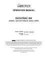
OPERATION MANUAL
DATATRAC 400
ARINC 429 DATABUS ANALYZER
MANUAL NUMBER: 06-1403-01 (Hard Copy)
E6-1403-01 (CD-ROM)
REVISION: 0
DATE: 09/26/2006
WARNING: INFORMATION SUBJECT TO EXPORT CONTROL LAWS
This manual may contain information subject to the International Traffic in Arms Regulation (ITAR) or the Export
Administration Regulation (EAR) which may not be exported, released, or disclosed to foreign nationals inside or
outside of the United States without first obtaining an export license. A violation of the ITAR or EAR may be
subject to a penalty of imprisonment and/or fines under 22 U.S.C.2778 of the Arms Export Control Act or section
2410 of the Export Administration Act. Include this notice with any reproduced portion of this document.
This document is proprietary to Aeroflex, and is not to be reproduced or otherwise
disseminated without the written consent of Aeroflex.
400 New Century Parkway – New Century, Kansas – 66031
Telephone: (800) 237-2831 / (913) 764-2452 Fax: (913) 782-5104
www.aeroflex.com
Safety and Regulatory Information
Review this product and related documentation to familiarize yourself with
safety markings and instructions before you operate this equipment.
WARNING
The WARNING notice denotes a hazard. It calls attention to a procedure,
practice, or the like, that, if not correctly performed or adhered to, could result in
personal injury. Do not proceed beyond a WARNING notice until the indicated
conditions are fully understood and met.
CAUTION
The CAUTION notice denotes a hazard. It calls attention to an operating
procedure, practice, or the like, which, if not correctly performed or adhered to,
could result in damage to the product or loss of important data. Do not proceed
beyond a CAUTION notice until the indicated conditions are fully understood and
met.
Caution (refer to accompanying documents). Attention – refer to the manual.
This symbol indicates that information about usage of a feature is contained in
the manual.
IMPORTANT!
WARNING
The mains (ac) fuse holder and the dc fuse holder are located on the Rear Panel.
An accessory kit of fuses and fuse carriers (caps) is provided, see item ACC4.
For international requirements for JPN 01-1403-00 and 01-1403-02 units the
following fuses must be used: Install an IEC style, 5 mm X 20 mm, 1.6 A, 250 V,
Type F fuse (ACC4F3) into the ac fuse holder, A12XF2 (fuse A12F2), with the
proper fuse carrier (ACC4MP2). Also install an IEC style, 5 mm X 20 mm, 1.6 A,
250 V, Type F fuse (ACC4F3) into the dc fuse holder, A12XF1 (fuse A12F1), with
the proper fuse carrier (ACC4MP2).
For the USA: Install a ¼ X 1 ¼ inch, 1.5 A, 250 V, slow-blow fuse (ACC4F2) into
the ac fuse holder, A12XF2 (fuse A12F2), with the proper fuse carrier
(ACC4MP1). Also install a ¼ X 1 ¼ inch, 1.5 A, 250 V, fast-blow fuse (ACC4F1)
into the dc fuse holder, A12XF1 (fuse A12F1), with the proper fuse carrier
(ACC4MP1).
For all other markets check with the proper authorities for which of these kinds of
fuses to use.
Equipment Markings
The following markings may appear on this equipment:
Direct current. This symbol indicates that the equipment requires direct current
input.
Alternating current. This symbol indicates that the equipment requires
alternating current input.
Both direct and alternating current. This symbol indicates that the equipment
requires either ac or dc input at the same connector.
3
Three-phase alternating current. This symbol indicates that the equipment
requires 3-phase ac input.
Earth (ground) terminal. This symbol indicates the ground (earth) terminal.
Protective conductor terminal. This symbol indicates the protective ground
(earth) terminal.
Frame or chassis terminal. This symbol indicates the frame or chassis terminal
for connection to ground.
Equipotentiality. This symbol indicates an equipotentiality terminal.
On (Supply). This symbol indicates that the power line switch is ON.
Off (Supply). This symbol indicates that the power line switch is OFF.
Standby. This symbol indicates that the power line switch is in STANDBY.
Caution, risk of electric shock. Danger – high voltage.
Caution, hot surface. Danger – high temperature surface.
Caution (refer to accompanying documents). Attention – refer to the manual.
This symbol indicates that information about usage of a feature is contained in
the manual.
In-position of a bistable push control. This symbol indicates the in (on)
position of a bistable push control.
Out-position of a bi stable push control. This symbol indicates the out (off)
position of a bi stable push control.
CE Mark. ™ of the European Community.
Fuse Symbol. To indicate a fuse.
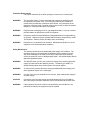
Warnings
WARNING
Do not use the equipment in a manner not specified in this manual!
WARNING
Equipment should only be serviced by authorized personnel.
WARNING
To avoid fire hazard, use only a fuse identical in type, voltage rating, and current
rating as specified in this manual.
Do Not Operate in Explosive Atmospheres
To avoid explosion, do not operate the equipment in an atmosphere of explosive
gas.
Do Not Attempt to Operate if Protection may be Impaired.
If the equipment appears damaged or operates abnormally, protection may be
impaired. Do not attempt to operate it. When in doubt, have the equipment
serviced.
WARNING
Keep the equipment dry to avoid electrical shock to personnel or damage to the
equipment. To prevent damage, never apply solvents to the equipment housing.
For cleaning, wipe the equipment with a cloth that is lightly dampened with water,
mild detergent, or alcohol. Do not use aromatic hydrocarbons, chlorinated
solvents, or methanol-based fluids.
Ventilation Requirements
For proper ventilation do not block openings in bottom cover or back panel.
WARNING
This is a Safety Class 1 Product (provided with a protective earthing ground
incorporated in the power cord). The mains plug shall only be inserted in a
socket-outlet provided with a protective earth contact. Any interruption of the
protective conductor inside or outside of the product is likely to make the product
dangerous. Intentional interruption is prohibited.
WARNING
Equipment has recharging circuit for a rechargeable battery. Use only a sealed
lead-acid battery as specified by JcAIR Test Systems.
WARNING
Equipment contains a sealed lead-acid rechargeable battery not replaceable by
an operator. Replace only with a sealed lead-acid battery as specified by JcAIR
Test Systems. Observe polarity of battery when reconnecting.
WARNING
Equipment is not intended for wet locations. Miscellaneous liquids on or in the
equipment could cause hazardous conditions.
Safety Maintenance.
The operator should check the detachable power supply cord condition. The
equipment should not be operated if the appliance inlet is cracked or broken.
Any obvious damage to the case (from a drop or fall) should be checked by
service personnel for loose or damaged parts inside. See individual parts lists for
approved replacement parts.
WARNING
The ON/OFF switch (A12S1) only controls dc voltage to the switch mode power
supply (A2) that sources the operating circuitry. The battery (A13A2BT1) is
always charging when there is mains power or dc power applied.
WARNING
To effect primary (mains) disconnect unplug the detachable power supply cord
at the appliance coupler or the mains plug.
WARNING
Connect unit to only one external source at a time, either mains power supply or
dc power supply.
CAUTION
Connection to the dc power supply input dual banana jack (A12J10) shall be
with a dual plug so that both conductors can be disconnected at the same time.
WARNING
If this equipment is used in a manner not specified by the manufacturer, the
protection provided by the equipment may be impaired.
ELECTROSTATIC DISCHARGE GENERAL WARNINGS FOR ALL EQUIPMENT
CAUTION:
THIS EQUIPMENT MAY CONTAIN ELECTROSTATIC DISCHARGE (ESD) SENSITIVE
COMPONENTS. TO PREVENT ESD SENSITIVE EQUIPMENT FROM POSSIBLE
DAMAGE, OBSERVE THE FOLLOWING PRECAUTIONS WHEN HANDLING ANY ESD
SENSITIVE COMPONENTS, OR UNITS CONTAINING ESD SENSITIVE
COMPONENTS:
a.
Maintenance or service personnel must be grounded though a conductive wrist strap, or a similar
grounding device, using a 1 MΩ series resistor for equipment protection against static discharge,
and personal protection against electrical shock.
b.
All tools must be grounded (including soldering tools) that may come into contact with the
equipment. Hand contact will provide sufficient grounding for tools that are not otherwise
grounded, provided the operator is grounded through an acceptable grounding device such as a
wrist strap.
c.
Maintenance or service of the unit must be done at a grounded, ESD workstation.
d.
Before maintenance or service of the equipment, disconnect all power sources, signal sources,
and loads connected to the unit.
e.
If maintenance or service must be performed with power applied, take precautions against
accidental disconnection of equipment components. Specifically, do not remove integrated
circuits or printed circuit boards from equipment while the equipment has power applied.
f.
All ESD sensitive components are shipped in protective tubes or electrically conductive foam.
The components should be stored using the original container/package when not being used or
tested. If the original storage material is not available, use similar or equivalent protective
storage material.
g.
When ESD sensitive components are removed from a unit, the components must be placed on a
conductive surface, or in an electrically conductive container.
h.
When in storage or not being repaired, all printed circuits boards must be kept in electrically
conductive bags, or other electrically conductive containers.
i.
Do not unnecessarily pick up, hold, or directly carry ESD sensitive devices.
Failure to comply with these precautions may cause permanent damage to ESD sensitive devices. This
damage can cause devices to fail immediately, or at a later time without apparent cause.
05-0035-00 Rev 03
Aeroflex Maintenance Manual
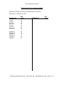
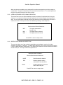
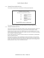
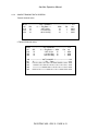
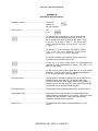
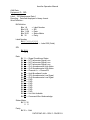
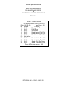
REVISION HISTORY BY DRAWING NUMBER
MANUAL: DATATRAC 400 ARINC 429 Databus Analyzer Operation
REVISION: 0 – September 26, 2006
DRAWING NO.
REV.
LEVEL
Section I
Section II
Section III
Section IV
Section V
Section VI
Section VII
Section VIII
00
00
00
00
00
00
00
00
Appendix A
Appendix B
Appendix C
Appendix D
Appendix E
Appendix F
00
00
00
00
00
00
DRAWING NO.
REV.
LEVEL
DRAWING REVISION HISTORY – DATATRAC 400 – SEPTEMBER 26, 2006 – PAGE 1 OF 1
Aeroflex Operation Manual
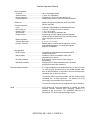
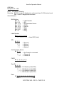
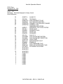
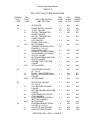
TABLE OF CONTENTS
SECTION I
1.
1.1
1.2
1.3
1.3.1
1.3.2
1.3.3
1.3.4
Introduction to the DATATRAC 400 .............................................1-1
Summary of Features...................................................................1-1
Reference Documents .................................................................1-2
Physical Description .....................................................................1-2
General ........................................................................................1-2
Front Panel Description................................................................1-2
Rear Panel Description ................................................................1-4
Internal Architecture .....................................................................1-6
SECTION II
2.
2.1
2.2
Installation Information .................................................................2-1
Unpacking and Inspection ............................................................2-1
General Power On Procedures ....................................................2-2
SECTION III
3.
3.1
3.1.1
3.1.2
3.1.3
3.1.4
3.1.4.1
3.1.5
3.1.6
3.2
3.2.1
3.2.1.1
3.2.1.2
3.2.2
3.2.3
3.2.3.1
3.2.3.2
3.2.4
3.2.5
3.3
3.3.1
3.3.2
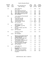
Receive Mode ..............................................................................3-1
Primary Receive Setup.................................................................3-1
Receive Channel Selection ..........................................................3-2
Receive Channel ON/OFF ...........................................................3-2
Receive Bus Speed Selection ......................................................3-3
Receive Select Labels..................................................................3-4
Select Label Setup .......................................................................3-4
Equipment ID Codes ....................................................................3-5
Label Data Definitions ..................................................................3-6
Default Receiver Setup Options ...................................................3-7
Receiver Data Format Selection ..................................................3-8
User Defined Data Format Setup .................................................3-10
Receive Mode Graphics Format...................................................3-14
Interval (Receive Rate) Format Selection.....................................3-16
Receive Data Download Selection ...............................................3-16
Digital To Analog Conversion Setup.............................................3-17
Digital To RS-232 Data Conversion .............................................3-17
Receive Data Display Lines Selection..........................................3-19
Receive Bus Monitor Sensitivity Selection ...................................3-20
Real-Time Data Display Screen ...................................................3-21
Data Display.................................................................................3-21
Real Time Keystrokes ..................................................................3-24
DATATRAC 400 – REV 0 - PAGE - i
Aeroflex Operation Manual
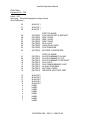
SECTION IV
4.
4.1
4.1.1
4.1.2
4.1.3
4.1.4
4.1.5
4.2
4.2.1
4.2.2
4.2.3
4.2.4
4.3
4.3.1
4.3.2
4.3.3
4.3.4
4.3.5
4.3.6
4.4
4.4.1
4.4.2
4.4.3
4.5
Transmit Mode .............................................................................4-1
Primary Transmit Setup Screen ...................................................4-1
Transmitter Channel Selection .....................................................4-2
Transmitter Channel On/Off .........................................................4-2
Transmitter Bus Speed Selection.................................................4-3
Transmitter Mode Selection .........................................................4-3
Equipment ID Codes ....................................................................4-4
Transmitter Default Setup Options ...............................................4-4
Transmitter Data Format ..............................................................4-5
Transmit Display On/Off ...............................................................4-5
Transmit Display Lines Selection .................................................4-7
Transmit Word Bit Gap Selection .................................................4-7
Static Transmit Data Keyboard Entry And Display .......................4-7
Real Time Data Display Screen ...................................................4-8
Alternate Transmit Edit Screen ....................................................4-10
Transmit Data Editing...................................................................4-11
Sample Transmit Data Screens ...................................................4-13
Burst Mode Transmission.............................................................4-15
Framing Label Transmissions ......................................................4-15
Dynamic Data Transmission ........................................................4-20
Label And Control Information Setup ...........................................4-20
Waveform Definitions ...................................................................4-21
Transmit Data Display ..................................................................4-21
Prestored Transmit Tables ...........................................................4-22
SECTION V
5.0
5.1
5.1.1
5.1.2
5.1.3
5.1.4
5.1.5
5.1.6
5.2
5.3
5.4
5.5
5.5.1
5.5.2
5.5.2.1
5.5.2.2
5.5.2.3
5.5.2.4
Record Mode................................................................................5-1
Primary Record Setup Screen......................................................5-1
Function Setup .............................................................................5-1
Channel Selection ........................................................................5-2
Record Interval.............................................................................5-2
Bus Speed....................................................................................5-2
Equipment ID Codes ....................................................................5-2
Label-SDI .....................................................................................5-2
Active Recording Screen..............................................................5-2
Record Capacity...........................................................................5-3
Recorded Data Protection ............................................................5-3
Recorded Data Review ................................................................5-3
Numerical Data Review................................................................5-3
Graphic Display of Recorded Data...............................................5-5
Graphics Screen Setup ................................................................5-5
Time Scale ...................................................................................5-6
Vertical Scale ...............................................................................5-6
Utility Functions............................................................................5-6
DATATRAC 400 – REV 0 - PAGE - ii
Aeroflex Operation Manual
SECTION V (Con’t)
5.5.3
5.5.4
DAC Download of Recorded Data................................................5-7
RS-232C Download of Recorded Data.........................................5-8
6.
6.1
6.1.1
6.1.2
6.1.3
6.1.4
6.1.5
6.1.6
6.1.7
6.2
6.3
6.4
SECTION VI
Breakpoint Mode ..........................................................................6-1
Breakpoint Setup..........................................................................6-1
Function Setup .............................................................................6-1
Break Sequence...........................................................................6-2
Break History................................................................................6-2
Relative Time ...............................................................................6-3
Selected History Labels................................................................6-3
Event Count .................................................................................6-4
Label/Data Setup .........................................................................6-4
Breakpoint Review .......................................................................6-4
RS-232 Download of Break History Data .....................................6-7
Break History Transmit Function ..................................................6-8
SECTION VII
7.0
7.1
7.2
7.2.1
7.2.2
7.3
7.3.1
7.3.2
7.4
7.5
7.6
Bite Mode .....................................................................................7-1
Bite Setup Menus.........................................................................7-1
CFDS Operation...........................................................................7-3
CFDS Normal Mode .....................................................................7-3
CDFS Menu Mode .......................................................................7-5
CMC Bite Operation .....................................................................7-7
Ground Test .................................................................................7-9
Shop Fault Menus ........................................................................7-10
737-Bite Mode..............................................................................7-10
Bite Screen Recording And Review .............................................7-13
RS232 Download of Saved Screens ............................................7-14
SECTION VIII
8.0
BILLS OF MATERIALS, ASSEMBLY DRAWINGS, AND SCHEMATICS
Appendix A...................................................................................................A-1
Appendix B...................................................................................................B-1
Appendix C...................................................................................................C-1
Appendix D...................................................................................................D-1
Appendix E...................................................................................................E-1
Appendix F ...................................................................................................F-1
DATATRAC 400 – REV 0 - PAGE - iii
Aeroflex Operation Manual
SECTION I
1.0
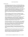
INTRODUCTION TO THE DATATRAC 400
This manual is furnished to customers of Aeroflex to provide detailed instructions for the operation of
the DATATRAC 400 ARINC 429 bus analyzer. It contains all necessary illustrations and information
to allow the unit to be properly interfaced with appropriate electronic equipment. The general
capabilities of the DATATRAC 400 are discussed in the paragraphs below.
1.1
SUMMARY OF FEATURES
DATATRAC 400 is a four receiver channel and four transmit channel ARINC 429 bus analyzer
(Channels 3 & 4 are optional for both receive and transmit functions).
The primary modes are Receive, Transmit, Record, Break, and BITE. Also available is an optional
Williamsburg Protocol Analyzer mode. This option is addressed in a separate user manual.
The Receive mode allows data to be read from all installed channels at either low (12.5 kHz) or high
(100 kHz) speed. All labels on the bus will be received. The data may be viewed in nine different
formats: hex, binary, engineering (standard and user defined). ASCII. And graphic time plots. Data
can be downloaded via an RS-232C port and a D/A converter port.
The Transmit mode allows up to 128 labels per channel to be transmitted at either low or high speed.
Other modes supported are dynamic data, prestored tables, burst, and retransmission of recorded
data.
The Record mode allows up to 16 labels to be recorded at a selected sample interval between 1 ms
to 10 s. Up to 120 kbytes of memory are available for storage.
The Break mode permits intermittent conditions to be trapped and history data to be collected in
memory. Multi-level break conditions can be defined for trapping data.
The BITE mode, supports systems on 737-300/400/500, 747-400, MD-11, and A320-330/340 aircraft.
Up to 240 BITE screens can be saved for later viewing or downloading. ARINC 604 normal and
interactive modes are supported.
Product specification is in Appendix B.
A database corresponding to ARINC 429-16 is prestored in the DATATRAC 400 EPROM memory.
This defines range, scaling, units, etc. to be used in displaying data for various modes. Also included
in the database are special Boeing labels used by equipment in Boeing aircraft. A complete list of
definitions for these labels is included in Appendix D.
DATATRAC 400 – REV 0 – PAGE 1-1
Aeroflex Operation Manual
1.2
REFERENCE DOCUMENTS
The following is a list of references referred to in this manual:
1. ARINC 429-16 SPECIFICATION
2. SPECIAL BOEING LABEL DEFINITIONS FOR ARINC 429
3. DATATRAC 400 WILLIAMSBURG PROTOCOL ANALYZER USER’S MANUAL VERSION B
1.3
PHYSICAL DESCRIPTION
1.3.1
GENERAL
The DATATRAC 400 is packaged in an aluminum enclosure complete with handle, front panel, rear
panel, and an internal card cage configuration consisting of mother board and plug-in application
boards. Units may be configured with optional front acrylic cover and rear plastic cover.
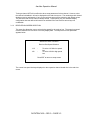
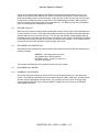
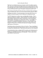
1.3.2
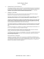
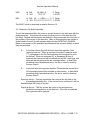
FRONT PANEL DESCRIPTION
The front panel configuration shown in Figure 1 contains a LCD, a keyboard area, display contrast
control, and the receiver/transmitter connectors.
LCD
The liquid crystal display (LCD) provides 16 lines x 40 characters in the character mode. It can also
be operated in a graphics mode to display time plots of data, with a resolution of 240 dots by 128
dots.
The contrast control for the display is located to the lower right of the display. This may be adjusted
at any time to optimize the viewing of the display.
Keyboard
Three key areas are located to the right of the display. The first is a vertical column of four function
keys (RCV, XMT, RCD, and BRK). The next key area consists of a 4 x 4 hexadecimal keypad for
general data entry. The third key area consists of the six keys to the far right. Four buttons contain
up, down, left, and right arrows and are used for various utility functions dependent on mode.
Generally, the up/down keys are used to increment vertically through data lists. The left and right
buttons are used to move the cursor laterally, sequence through setup options, or call help menus
appropriate to the existing mode of screen. Located below the arrow keys are the clear (CLR) and
enter (ENT) buttons.
DATATRAC 400 – REV 0 – PAGE 1-2
Aeroflex Operation Manual
DATATRAC 400 FRONT PANEL OVERVIEW
FIGURE 1
DATATRAC 400 – REV 0 – PAGE 1-3
Aeroflex Operation Manual
Databus Connectors
Two rows of four BNC connectors provide the databus interfaces for the input receive and output
transmit channels. The inner conductor on each BNC connector is the A signal (High), of the ARINC
429 bus. The outer conductor is the B signal (Low). The channels are labeled appropriately.
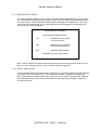
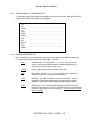
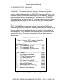
1.3.3
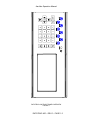
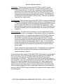
REAR PANEL DESCRIPTION
The rear panel shown in Figure 2 contains the ON/OFF switch, power connector for dc power, power
connector for mains power, the fuse holders, RS-232C connector, the DAC port connectors, and the
unit serial number tag.
ON/OFF Switch
The ON/OFF switch applies power to the display and all electronic circuits.
Dc Power Input
The red and black banana jacks can be used to apply an input of 28 V dc. The power source should
be capable of supplying up to 21 W.
Mains Power Input
Mains power can be applied to the three prong connector. The range of this input is 115 to 230 V ac,
50 to 400 Hz, at a maximum of 350 mA.
Internal Battery Power
The unit may also be operated from the internal battery. The battery is a 12 V, 7 Ah sealed lead-acid
battery. A fully charged battery will normally provide up to 6 h of operation. This battery is also used
to retain RAM memory for an indefinite period. RAM memory will be retained even when the battery
has discharged below the level required to operate the unit. The internal battery can be charged with
the application of either dc or mains power. The charge function employs three levels for rapid and
efficient charging. The lower maintenance level may be left on indefinitely.
DATATRAC 400 – REV 0 – PAGE 1-4
Aeroflex Operation Manual
DATATRAC 400 REAR PANEL OVERVIEW
FIGURE 2
DATATRAC 400 – REV 0 – PAGE 1-5
Aeroflex Operation Manual
Fuses
Two power input fuses (dc and ac) are located on the rear panel. These fuses should be checked
after any failure of the unit to power up properly.
RS-232 Connector
An RS-232 connector is located on the rear panel and can be configured by the operator to output
received or recorded data. Appendix A contains detailed information on interfacing this output to
other RS-232 devices.
DAC Connector
Two BNC connectors are located on the rear panel and each provides a DAC (digital to analog
converter) channel that can be configured by the operator to output converted data or a trigger pulse
(refer to sections 3-7 for more detail). The inner conductor is the signal side. The outer conductor is
connected to ground. DAC channel 1 is available when Receive Board 1 (RCV channel 1 and 2) is
present. DAC channel 2 is available when Receive Board 2 (RCV channels 3 and 4) is present.
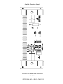
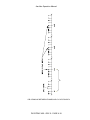
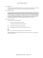
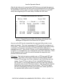
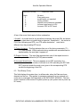
1.3.4
INTERNAL ARCHITECTURE
Internally, the unit contains a card cage, and the battery assembly. The card cage arrangement
consists of a front plane and the following plug in cards:
- Power supply
- CPU/memory
- Receiver Ch. 1/2
- Transmitter Ch. 1/2
- Receiver Ch. 3/4 (optional)
- Transmitter Ch. 3/4 (optional)
The internal configuration is illustrated in Figure 3.
DATATRAC 400 – REV 0 – PAGE 1-6
Aeroflex Operation Manual
DATATRAC 400 INTERNAL CONFIGURATION
FIGURE 3
DATATRAC 400 – REV 0 – PAGE 1-7
Aeroflex Operation Manual
SECTION II
2.0
INSTALLATION INFORMATION
2.1
UNPACKING AND INSPECTION
The DATATRAC 400 has been carefully packed to survive all normal shipping and handling
conditions. It is important that the customer immediately inspect the received shipment to ensure that
all items are present and undamaged.
Contents:
1.
2.
3.
4.
DATATRAC 400 unit
RS Read program for data download to a PC
Power Cord
Manual
WARNING
Inspect all items thoroughly for physical damage. If no damage is evident,
apply mains or dc power to the unit and change on/off switch to ON. A power
on screen should appear on the display (see section 2.2). If a problem is
encountered at this point, contact an Aeroflex representative for assistance.
DO NOT OPEN THE UNIT AND ATTEMPT REPAIRS AS THIS WILL VOID
THE WARRANTY.
CAUTION
The internal battery should be in a charged state when it is received.
However, as a precaution it is recommended that the unit be connected to
external power overnight before attempting to operate from the internal
battery.
2.2
GENERAL POWER ON PROCEDURES
External power (dc or mains) can be applied or the unit can be operated on the internal battery. If a
unit fails to operate properly on power up, the fuses located on the rear panel should be checked.
Upon initial power up of the unit, the various mode setup values will be in indeterminate states. To
reset these values to their defaults, first press the CLR key, then the 0 key. This initialization may
also be necessary if an erroneous data condition is suspected during real-time operation of the unit,
possibly caused by an inadequate battery backup.
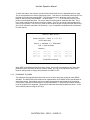
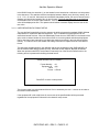
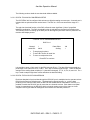
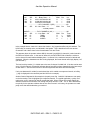
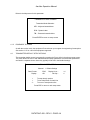
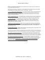
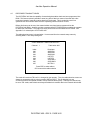
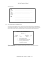
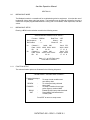
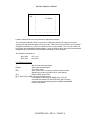
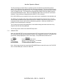
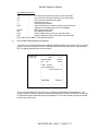
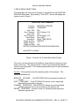
After turning the on/off switch to the ON position, the following screen will appear on the display (a
reminder: the contrast control may be adjusted at any time to optimize the viewing of the display).
DATATRAC 400 – REV 0 – PAGE 2-1
Aeroflex Operation Manual
** DATATRAC 400 **
S/W Version 025 **
Configuration: 2 RCV, 2 XMT Channels
RCV : Receive Data
XMT : Transmit Data
RCD : Record Data
BRK : Break on Receive Data
B
: Display BITE Data
D
: Recall System Setups
Select function : RCV
Press :ENT to continue
(Copr. 1991-97 Atlantic Instruments, Inc.)
The version number of the current software package contained in the DATATRAC 400 unit is always
displayed on the first line of the power on menu. This information may be useful when reporting
problems experienced in the field.
The configuration of the DATATRAC 400 unit is given on the second line of the menu. The number of
received channels and the number of transmit channels contained on the unit and available for
operation are listed.
The desired function can be selected from the list of options by pressing one of the four keys, the B
key (for BITE mode operation), or the D key (for recalling system table) from the hexadecimal keypad.
When the desired selection is displayed on the screen, the user “enters” the choice by pressing the
ENT key. Control will proceed to the appropriate setup screen based on the function selected.
DATATRAC 400 – REV 0 – PAGE 2-2
Aeroflex Operation Manual
SECTION III
3.0
RECEIVE MODE
The receive mode consists of a primary setup screen, a secondary setup screen (referred to as the
"Defaults" screen) and a real-time data display screen. There are also various help screens
associated with each setup parameter. Depending on the system setup, the real-time screen may
also be shared by one or more transmit channels. Additional setup screens are provided for special
modes that may be selected.
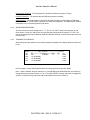
3.1
PRIMARY RECEIVE SETUP
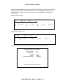
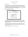
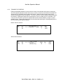
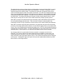
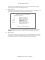
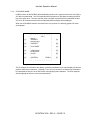
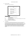
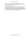
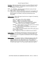
After a receive mode selection (RCV), the following receive setup screen will appear.
* RECEIVER SETUP *
Channel: 1
On/Off: : OFF
Bus Speed: 12.5
>
<
^v
D
Select Lbls: ALL
Equipment ID: 002
To step through options
To see Help screen for each line
To move to next/previous line
To edit defaults
Press ENT to continue or any
function key to change functions
Each setup parameter will initially contain its default value unless changed by a previous setup
session. Before the operator can proceed to the real-time data display screen, a receive channel
must be enabled by setting On/Off to ON. If the user does not wish to change the other default
settings, the ENT key may be pressed to continue to the data display (real-time) screen.
At any time while in the setup screens, pressing the CLR key will reset all the parameters to their
default values. The unit will ask for a confirmation (the C key confirms the action) before continuing
with the reset.
Another function of the CLR key is to return to the Main Menu screen. This permits accessing the
system setup recall function (since there is no dedicated key for this function). After pressing the
CLR key, the unit will ask for a confirmation. Pressing F at this point will cancel the initialization and
return to the Main Menu.
DATATRAC 400 – REV 0 – PAGE 3-1
Aeroflex Operation Manual
To change the current settings, the arrow keys should be pressed as instructed on the setup screen.
The right arrow sequentially steps through the setup options. The left arrow presents a HELP menu
with information pertinent to the particular parameter selection. The user may return from a help
menu at any time by pressing ENT.
There is an additional list of parameters, accessible in the Receiver Default menu (section 3.2), that
control aspects of the receive function.
The following sections describe each parameter listed in the Receiver Setup screen along with the
help screens associated with each. The help screens are invoked by pressing the HELP key.
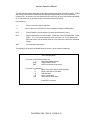
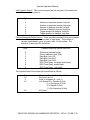
3.1.1
RECEIVER CHANNEL SELECTION
This setup line allows the user to select channels 1 or 2 (1-4 if the additional receiver card is installed)
for setting up that channel. The channel number may be selected by typing the value directly or by
using the > (right arrow) key to step through the options. Once a channel has been selected, all other
parameter selections will apply only to that channel. This allows each individual channel to be
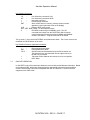
uniquely configured. The help screen for this setup line is shown below (assuming a single receive
board is installed) :
* RECEIVER HELP SCREEN *
Receiver Channel Selection:
1 - To select channel 1
2 - To select channel 2
3 – Not installed
4 – Not installed
Press ENT to return to setup screen
3.1.2
RECEIVER CHANNEL ON/OFF
This setup line is used to enable the currently selected channel for receiving and displaying data.
The help screen for this parameter is shown here:
* RECEIVER HELP SCREEN *
Receiver Channel On/Off Options:
ON - To enable the channel for
receiving data.
OFF - To disable the channel.
Press ENT to return to setup screen
DATATRAC 400 – REV 0 – PAGE 3-2
Aeroflex Operation Manual
Turning a channel OFF will not affect the other setup parameters for that channel. However, since
the channel is disabled, it will not be displayed on the real-time screen. The remaining active channel
windows (receive and transmit, if any) on the real-time screen will be resized to their default values.
This will insure that the full screen is always utilized. Consequently, any non-standard display
configuration that was defined will need to be redefined if the new real-time screen layout is
undesirable.
3.1.3
RECEIVER BUS SPEED SELECTION
This setup line allows the user to select the bus speed for the receiver bus. The proper bus speed
must be selected for the receiver to correctly display data. The help screen for this parameter
appears below:
* RECEIVER HELP SCREEN *
Receiver Bus Speed Selection:
12.5
-
100
-
To select 12.5 KHz low speed
bus
To select 100 KHz high speed
bus
Press ENT to return to setup screen
The current bus speed is always displayed on the respective channel header line in the real-time
screen.
DATATRAC 400 – REV 0 – PAGE 3-3
Aeroflex Operation Manual
3.1.4
RECEIVE SELECT LABELS
This setup parameter allows the user to control which labels will be displayed on the real time screen.
ALL mode causes every label being received on the bus (up to 256 labels x 4 SDI's) to be displayed
in numerical order. Common labels with different SDIs are displayed on separate lines. SEL mode
causes only the selected labels (up to 16 labels per channel) to be displayed in any desired order.
The help screen for this parameter is:
* RECEIVER HELP SCREEN *
Receive Select Labels Selections:
ALL
-
Display all incoming labels
for current channel.
SEL
-
Display previously selected
labels for current channel.
EDIT
-
Setup/edit selected labels.
Press ENT to return to setup screen
EDIT is selected when the operator needs to access the list of labels being selected either to review
them or to make changes to the list. The next section details this operation.
3.1.4.1 SELECT LABEL SETUP
The select-labels facility permits the operator to filter out any unnecessary labels that would otherwise
clutter up the real time display screen. It also enables the operator to organize the displaying for
some order other than numeric by label (which is the case in ALL mode). This permits the viewing of
two related labels next to each other and eliminates the inconvenience of scrolling the display from
one label to the other.
DATATRAC 400 – REV 0 – PAGE 3-4
Aeroflex Operation Manual
To utilize this feature, the operator must first define which labels are to be displayed and their order.
This is accomplished in the Select Label Setup screen. This screen is accessed by selecting EDIT as
the Select Lbls option and pressing ENT. The following menu then allows the user to enter new
labels or edit previously entered labels. The arrow keys ( ^ , < , > , v) are used to move the cursor
position to the desired label field. The cursor cannot move beyond an undefined label field. The A
key is used to add (insert) at the current cursor position. The E key is used to erase the label at the
current cursor position. The CLR key is used to clear all labels for the currently selected channel only
(the unit will request a confirmation of this action). Up to 16 label/SDI combinations can be selected
for each channel.
* SELECT LABEL SETUP *
Format: Lbl-S (Lbl = Octal, S = 0, 1, 2, 3,
or D for don't care)
Keys: A = Add label, E = Erase label,
CLR = Clear all entries
Channel: 1
____ - ___
____ - ___
____ - ___
____ - ___
____ - ___
____ - ___
____ - ___
____ - ___
____ - ___
____ - ___
____ - ___
____ - ___
____ - ___
____ - ___
____ - ___
____ - ___
Press ENT to continue
When EDIT is selected at the Receiver Setup screen, the unit will automatically set the Select Lbls
parameter back to SEL after the above screen is exited. The user is not required to return to the
Receiver Setup screen to change this parameter from EDIT to SEL.
3.1.5
EQUIPMENT ID CODES
The equipment ID code should be entered for the unit to select the proper scaling for each ARINC
429 label. The DATATRAC-400 contains a full implementation of the ARINC 429-16 specification for
stand alone words. Some labels may have multiple interpretations when displayed in engineering
units and the equipment ID determines the correct interpretation. A help menu provides a reference
list of all equipment ID's supported. Equipment ID codes are three-digit hexadecimal values. A new
value is directly entered using the 0-F keys.
DATATRAC 400 – REV 0 – PAGE 3-5
Aeroflex Operation Manual
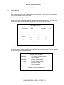
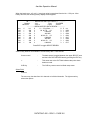
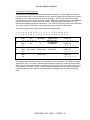
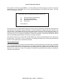
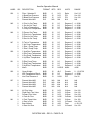
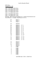
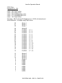
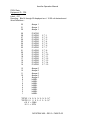
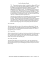
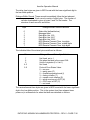
A portion of the help menu listing of all currently defined equipment ID codes that are supported by
the DATATRAC 400 appears below. The full listing is contained in Appendix D. The user may scroll
through the list one line at a time using the up and down arrows. The F (forward) and B (back) keys
move the list 10 lines at a time and may be used to scroll more rapidly. It may be more convenient for
the operator to have the list organized alphabetically rather than numerically. This may be
accomplished by pressing A as noted in the help screen header message.
* HELP SCREEN * Equipment ID Codes *
Press ^,v,B,F to scroll list,
A for alphabetic order, 0 for numeric
Press ENT to return to setup screen
001
002
003
004
005
006
007
008
009
00A
00B
00D
010
3.1.6
Flight Control Computer
Flight Management Computer
Thrust Control Computer
Inertial Reference System
Attitude and Heading Ref System
Air Data System
Radio Altimeter
Airborne Weather Radar
Airborne DME
FAC (A310)
Global Positioning System
AIDS Data Management Unit
Airborne ILS Receiver
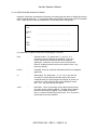
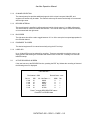
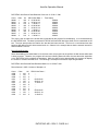
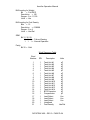
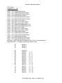
LABEL DATA DEFINITIONS
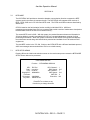
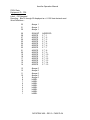
Since the user may not always be familiar with label assignments for parameters he is viewing, a help
menu gives label data definitions based on equipment ID. This menu is accessed from the Receive,
Transmit, Record or break data review screens by pressing the D key. The following example shows
the label definitions for equipment ID 004.
Label Definitions * Equipment ID = 004
Inertial Reference System
Lbl
Parameter Definition
010
Present Position-Latitude
011
Present Position-Longitude
012
Ground Speed
013
Track Angle-True
014
Magnetic Heading
015
Wind Speed
016
Wind Direction-True
041
Set Latitude
042
Set Longitude
043
Set Magnetic Heading
044
True Heading
Press ^,v.F,B to scroll, ENT to return
DATATRAC 400 – REV 0 – PAGE 3-6
Aeroflex Operation Manual
3.2
DEFAULT RECEIVER SETUP OPTIONS
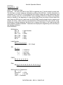
If the D key is pressed on the primary receiver setup menu, the following menu will appear, allowing
the user to edit additional defaults of the receive mode. (Note: pressing D at the equipment ID field
will be interpreted as a data entry.) These receive parameters are listed in a separate screen since
they typically will be left in their default settings.
* RECEIVER SETUP *
Channel 1 Default Settings
Data Format
Interval
Rcv Download
>
<
^v
: ENG
: INST
: NONE
Display Lines
Bus Monitor
To step through options
To see HELP screen for each line
To move to next/previous line
Press ENT to return to main setup menu
DATATRAC 400 – REV 0 – PAGE 3-7
: 14
: 4
Aeroflex Operation Manual
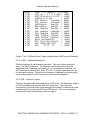
The following sections describe the settings of the various parameters above.
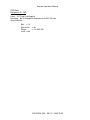
3.2.1
RECEIVER DATA FORMAT SELECTION
This setup line selects the format to be used initially by the receiver real-time display screen. The
format may also be changed in the display screen by pressing the right arrow (>) key. Two options
for this parameter that are not accessible from the real-time screen are EDIT and GRAPH. EDIT is
used to create or modify a user-defined data format (see next section). GRAPH enables the real time
graphic time plots of specified labels in lieu of the numerical display. The help screen for this
parameter gives examples of data lines displayed in each format:
* RECEIVER HELP SCREEN *
Data Display Format Options:
ENG - Engineering units
HEX19L - 19 bit data field-hex-LSB 1st
HEX19M - 19 bit data field-hex-MSB 1st
HEX32 - 32 bit hexadecimal
BIN19L - 19 bit data field-bin-LSB 1st
BIN19M - 19 bit data field-bin-MSB 1st
BIN32 - 32 bit binary
USER - Previously defined user format
EDIT - Define/edit user format
GRAPH - Realtime graphic plot
Press v for examples
Press ENT to return to setup screen
* RECEIVER HELP SCREEN *
Examples of Display Format Selections
given the following sample ARINC word:
Data: Label 210
Equip. ID = 06
Bit 32
24
16
9 8
1
01010100
11011001 10100010
00010001
ENG - Engineering units
Lbl SDI 11 ----- Eng Data --- *
210 10
-1427.19 Kts
SSM
10
Par
1
msec
0062
Press v for more examples
Press ENT to return to setup screen
DATATRAC 400 – REV 0 – PAGE 3-8
Aeroflex Operation Manual
* RECEIVER HELP SCREEN *
HEX19L - 19 bit data field - hex - LSB 1st
Lbl SDI 11-Hex Data-29
SSM
Par msec
210 10
166CA
10
1
0062
HEX19M - 19 bit data field - hex - MSB 1st
Lbl SDI 29-Hex Data-11
SSM
Par msec
210 10
A6CD0
10
1
0062
HEX32 - 32 bit hexadecimal
Lbl SDI 32-Hex Data-1
210 10 54 D9 A2 11
SSM
10
Par
1
msec
0062
Press v for more examples
Press ENT to return to setup screen
* RECEIVER HELP SCREEN *
BIN19L - 19 bit data field - bin - LSB 1st
Lbl SDI 11- -Binary Data - -29
SSM Par
210 10
0001011001101100101 10
1
msec
0062
BIN19M - 19 bit data field - bin - MSB 1st
Lbl SDI
29- -Binary Data- -11
SSM Par
210 10
1010011011001101000 10
1
msec
0062
BIN32 - 32 bit binary
Lbl 32- * --- * --- * Bin * Data --- * --- * --- 1msec
210 01010100110110011010001000010001 062
Press ENT to return to setup screen
The up and down-arrow keys page through the different help screens above. The USER format
presents data as ENG unless a different "sub-format" was defined for that label (see next section).
The ENG format (and USER format, if so defined) has the capability of displaying discrete bits if the
label definition in the ARINC 429-16 document specifies it. Note above that the ENG header line
contains an "11" just to the left of the data field. A discrete bit in the data word (bit 11) would be
displayed in this column as a 0 or 1. Additional discretes -from bit 12 and up are displayed to the
right.
DATATRAC 400 – REV 0 – PAGE 3-9
Aeroflex Operation Manual
In the BIN32 format, the asterisks (*) on the header line are intended as a reference to a bit's position
in the data word. The asterisks mark the boundaries between nibbles (every four bits), namely, bit 5,
9, 13, 17, 21, 25, and 29. Also note that in the BIN32 data display format, the receive interval (msec)
displays only three digits instead of four in other formats. The most significant digit is not displayed
on the data line due to screen width limitations. If the receive interval is greater than 999 msec, the
value will be displayed as 999. The operator should switch to another display format to see the full
rate value.
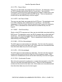
3.2.1.1 USER DEFINED DATA FORMAT SETUP
The user-defined format facility gives the operator the ability to bypass the standard ARINC 429 data
interpretation for a particular label and equipment. Up to 16 different format definitions can be
entered and stored at a time. When the data display format is set to USER DATA in the header of the
active receive channel window of the real time screen, the incoming labels and selected equipment
IDs for that channel are scanned for any labels that match those stored in the user-defined scaling
memory. If a match is found, the ARINC 429 scaling information is replaced with the user-defined
format.
The data types available within a user definition are the two engineering types, BNR and BCD, as
well as the direct data display formats HEX19L, HEX19M, HEX32, BIN19L, BIN19M, and BIN32.
When the operator selects EDIT at the Data Format setup line of the Receive Defaults menu, the
following screen is presented for defining the data format:
* USER DEFINED DATA FORMAT *
Format Number:
Equipment ID:
Label:
Format:
00
000
--HEX19L
Press ENT to return to setup screen
The format number is a value between 00 and 15 to be entered by the user. It serves as an index to
the sixteen format definitions.
If the equipment ID is left at 000, then all occurrences of the specified label will be processed
regardless of the equipment ID selected in the channel's setup screen.
DATATRAC 400 – REV 0 – PAGE 3-10
Aeroflex Operation Manual
An octal label must be entered before the cursor can advance to the format line. The > key is used to
step through the format options. If the engineering formats, BNR or BCD, are selected, additional
lines are displayed to enable the user to fully specify the bit format of the data word. For a BCD data
type, the format screen appears as follows:
* USER DEFINED DATA FORMAT *
Format Number:
Equipment ID:
Label:
Format:
Max Digit (1, 3, 7, 9):
Number of Digits (0-6):
Number of Discretes (0-7):
Range:
Units:
00
00
377
BCD
7
5
0
1234560
USR
Press ENT to return to setup screen
The Max Digit parameter is used to determine how many bits will de dedicated to the most significant
digit (MSD). The MSD always starts with bit 29 and occupies 1, 2,3, or 4 bits for a max digit of 1, 3, 7,
and 9, respectively. Thus for a max digit of 7, the MSD will occupy 3 bits, namely bits 27, 28, and 29.
This parameter controls the alignment of the other digits in the data word. See the ARINC 429
specification for the complete explanation of the BCD and BNR data formats.
Beyond the MSD, all remaining digits are packed contiguously with 4 bits per digit. If the number of
digits is set to less than 6, the remainder of the field is packed with zeros on the right. The position of
the decimal point is specified by the range parameter. The > key is used at the range line to adjust
the magnitude of the number. The choices for range are the following:
1234560
123456.
12345.6
1234.56
123.456
12.3456
1.23456
.123456
If the number of digits is less than 6, the undefined digits are set to 0. A 0 in the range indicates a
dummy place holder and not a decoded digit.
DATATRAC 400 – REV 0 – PAGE 3-11
Aeroflex Operation Manual
Discretes can be defined beginning with bit 11 as the first discrete. If, for instance, three discretes
are desired, entering a 3 for this parameter would decode bits 11, 12, and 13 and display these as
binary digits. The Units parameter allows the user to specify a three character string to either indicate
the units of the decoded value, or to simply identify the format definition. When the cursor is moved
to this line, the DATATRAC 400 will print keystroke instructions for incrementing or decrementing
through the ASCII table using the F and B keys. The > key is used to step to the next character when
the current character has been set.
The BNR format screen displays a slightly different set of parameters:
* USER DEFINED DATA FORMAT *
Format Number:
Equipment ID:
Label:
Format:
Full Scale Value:
Number of Bits (6-20):
Number of Discretes (0-7):
Range:
Units:
00
00
377
BNR
4
18
0
1234560
USR
Press ENT to return to setup screen
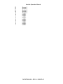
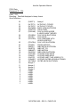
Full Scale Value specifies the magnitude (+ and -) of the decoded value. The full scale values are
discrete values that are predefined in the DATATRAC. They include all the full scale values currently
listed in the ARINC 429 specification. The > key is used to step through the options until the desired
full scale value is displayed. The choices currently defined are (in order they are stored):
4
180
4096
360
8
256
8192
65536
32
512
16384
262144
64
1024
32768
16
128
2048
131072
Beyond the last defined value (16), the unit will display integers followed by a question mark (?), such
as "19?", "20?", and so on up to "31?". These are full scale value storage areas yet to be defined.
The operator should avoid selecting one of these as the scaling will be unpredictable.
The number of bits specifies the number of significant bits (excluding the sign bit) to utilize in the
decode. The sign bit is always bit 29, and the most significant bit of data is 28. Refer to the ARINC
specification for a complete description.
DATATRAC 400 – REV 0 – PAGE 3-12
Aeroflex Operation Manual
Another user-defined format that may be specified is the ASCII format. This format is provided to
support character-oriented data encoding. There are actually two slightly different schemes in
common use for encoding 7-bit ASCII character data, namely PADDED and UNPADDED, as
illustrated below.
PADDED ASCII Encoding:
3
2
|P
|A
|R
2 2 2
5 4 3
|
|
|
Char 3
1 1 1
7 6 5
9 8
|P
|
|P
|A
| Char 2
|A
|D
|
|D
|
|
|
Char 1
|
|
| Label |
|
|
UNPADDED ASCII Encoding:
3 3 3
2 2
2 1 0
3 2
|P
|
|
|A
| SSM | Char 3
|R
|
|
1 1
6 5
9 8
|
|
| Char 2
| Char 1
|
|
|
| Label
|
When the user selects ASCII as the user-format, the screen will appear as follows:
* USER DEFINED DATA FORMAT *
Format Number:
Equipment ID:
Label:
Format:
Character Boundaries:
00
00
377
ASCII
PADDED
Press ENT to return to setup screen
DATATRAC 400 – REV 0 – PAGE 3-13
|
|
|
Aeroflex Operation Manual
3.2.1.2 RECEIVE MODE GRAPHICS FORMAT
Instead of viewing the received data numerically, the operator has the option of displaying incoming
labels as graphic time plots. To view graphics data, select GRAPH data format option in the default
menu. When the ENT button is pressed twice, the following screen is displayed:
TR1
CH1
_
L001-0
x1
_
+00%
_ _ _ _ _ _ _ _ _ _ _ _ _ _ _
_ _ _ _ _ _ _
_ _ _ _ _ _ _ _
_ _ _ _ _ _ _ _ _ _ _ _ _ _ _
_
TR2
CH0
_ _ _ _ _ _ _ _ _ _ _ _ _ _ _
_
Four fields can be edited to achieve the desired graph. These are:
CH#
-
Channel Number. The options are 0, 1, and 2, 3, or 4
(assuming 4 receive channels are available). This is the
receive channel that contains the data to be displayed
graphically. A selection of 0 on trace 2 will turn the second
trace off, enabling the entire screen to be used for trace 1 only
(this is the default).
L001-0
-
Label/SDI. Enter the octal Arinc 429 label and SDI to be displayed
graphically.
x1
-
Data scaling. The options are 1, 2, 4, 8, 16, 32, 64, and 128.
An option of 1 means that the full scale value of the word is
contained within the vertical height of the display, an option of 2
means that +/-50% of the full scale word is displayed, and so
forth. The > key steps through the options.
+00%
-
Data offset. This is a percentage of full scale that becomes the
zero point when the data is graphed. The data offset is applied
before the data scaling is applied. Any number from 00% to
99% (+/-) may be entered using the 0-9 keys. The > key can be
used to step to the next character.
DATATRAC 400 – REV 0 – PAGE 3-14
Aeroflex Operation Manual
The horizontal resolution of the graph is 200 dots. Therefore, for a receive interval of 100 ms it will
take 20 s to complete one sweep. When it reaches the end, the display will clear and the plot will
resume at the beginning. The relative time from the beginning of the sweep is displayed in seconds
on the display.
The vertical resolution of the graph is 64 dots for dual trace mode and 128 dots for single trace mode.
In addition to the keystrokes described above, other keystrokes that are active while in the graph
mode are:
^,v
-
Moves the cursor up or down through the setup fields.
ENT
-
Freezes the graphic plot. Toggle to unfreeze. HOLD will be
displayed in the upper right hand corner of the display. The
elapsed time continues to tick off internally when data is on
HOLD.
CLR
-
Data trace clears and starts over.
RCV, XMT, RCD, or BRK - Control is passed to the setup screen of the selected
function.
It is possible to display two separate plots simultaneously by enabling trace 2. The default is trace 2
off. This is indicated by the channel number of 0. To enable the trace, move the cursor down to the
channel of trace 2 and select the desired receive channel. The remaining setup lines will appear,
prompting the operator to define the plot parameters:
TR1
CH1
L001-0
x1
_
+00%
_ _ _ _ _ _ _ _ _ _ _ _ _ _ _
_ _ _ _ _ _ _ _ _ _ _ _ _ _ _ _ _ _ _
_ _ _ _ _ _ _ _ _ _ _ _ _ _ _
TR2
CH0
L001-0
x1
_
+00%
_ _ _ _ _ _ _ _ _ _ _ _ _ _ _
_ _ _ _ _ _ _ _ _ _ _ _ _ _ _ _ _ _ _
_ _ _ _ _ _ _ _ _ _ _ _ _ _ _
DATATRAC 400 – REV 0 – PAGE 3-15
Aeroflex Operation Manual
When two plots are enabled, the two sweeps will run at the same speed to permit time response
comparisons. The speed is dictated by the receive time interval of trace 1. The vertical position of
the trace 2 plot will remain at its last value received.
3.2.2
INTERVAL (RECEIVE RATE) FORMAT SELECTION
The receive rate is the time interval between successive receipts of a particular label for a given
channel. It is computed in milliseconds and displayed on the real time display line along with the
data. The user may select the format of this receive interval to be the instantaneous, minimum, or
maximum interval. The help menu below is available by pressing < at the setup line.
* RECEIVER HELP SCREEN *
Receive Interval Format Selections:
INST MIN MAX -
To display instantaneous
interval in ms
To display minimum interval
To display maximum interval
Press ENT to return to setup screen
3.2.3
RECEIVE DATA DOWNLOAD SELECTION
The user may select one of two modes for downloading received data in real time for further
evaluation, processing, or archiving. The DAC option allows the user to select a real time conversion
(12 bit) of digital data to an analog signal. The RS232 option allows the real time download of data to
the RS-232C port. The help screen for this parameter is:
* RECEIVER HELP SCREEN *
Receive Data Download Selections:
NONE
-
Data Download is disabled.
DAC
-
Realtime digital to analog
conversion of one data word.
RS232
-
Realtime download of received
data on RS-232C port.
Press ENT to return to setup screen
DATATRAC 400 – REV 0 – PAGE 3-16
Aeroflex Operation Manual
The following sections detail the two download utilities available.
3.2.3.1 DIGITAL TO ANALOG CONVERSION SETUP
The DATATRAC 400 is configured with at least one digital-to-analog converter port. A second port is
included with an optional second receive board. The DAC is a 12-bit converter with a range of +/10V.
The real-time download function of the DAC utilizes the most significant 12 bits of a specified
label/SDI combination. The DAC download function is selected from the Receiver Defaults menu.
The following screen for setting up the DAC port will then appear just before control is passed to the
real time data display screen:
* DIGITAL TO DC CONVERSION SETUP *
DAC Port: 1
Channel:
Label-SDI:
>
<
^v
1
000-0
Data Offset:
Scaling:
+00
1
To step through options
To see HELP screen for each line
To move to next/previous line
Press ENT to continue
It is possible to enter a "don't care" for the SDI (using the D key). The data offset is expressed as a
percentage of full scale from 0% to +/-99%. The F key is used to toggle the sign. There are discrete
settings for the scaling (data multiplier) of 1 (data left unchanged), 2, 4, 8, 16, 32, 64, and 128. The >
key is used to step through these values and select the desired scaling.
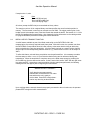
3.2.3.2 DIGITAL TO RS-232 DATA CONVERSION
Real time download of received data through the RS-232C port is enabled when the operator selects
RS-232 at the Receiver Defaults menu. The download is channel specific, i.e., only the data
pertaining to the channel under which the RS-232 was enabled will be downloaded. However, it is
possible to enable the RS-232C port for more than one channel at a time. Each data record (label
receipt) is transmitted over the RS-232C with the channel number as part of the data, so a host
computer receiving the data can distinguish which channel the data line pertains to.
DATATRAC 400 – REV 0 – PAGE 3-17
Aeroflex Operation Manual
There are different modes which utilize the RS-232C download, namely, recorded data download and
real time data download described here. In both cases, the bit format of a transmitted byte is the
same. These are:
1 start bit
8 data bits
1 parity bit (odd)
0 stop bits
Baud rate = 9600 bps
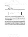
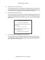
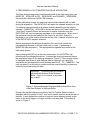
Just before control passes to the real time data display, the unit will display the following message
prompting the user to verify that the host is ready to receive data:
Make sure the RS232 port is connected properly and
that the RS232 receive port is ready to accept data.
Press ENT to begin download or any other key to
abort the transfer
The receiving program on the host should be invoked at this time to insure that no data is lost.
Because this is a real-time operation, the DATATRAC 400 is unable to wait for the host. If the
DATATRAC 400 detects that the host is not ready, it will simply skip the transmission of the record
pending. To abort the download, any key other than ENT is pressed at the screen above and the
DATATRAC 400 will return to the Receiver Setup screen. Note, however, that RS-232 download is
still selected in the default screen. An attempt to proceed to the real-time display will again present
the above message. To cancel the download, the operator must return to the Receiver Default menu
and select a download of "NONE."
The unit will only download data while control remains in the real time data display screen. If a
function keystroke causes control to pass to another screen, the RS-232C download will cease until
control passes back to the real time screen via the Receive Setup. That is, only when the operator
presses ENT from the Receiver Setup screen to proceed to the real time screen will the DATATRAC
400 check to see if the RS-232 download is enabled. If the operator enters the real time screen from
the Transmit Setup screen, the RS-232 port will stay in a standby mode and not transmit any data.
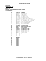
For real time data download, a total of eight bytes are sent over the RS-232 port per label received.
The structure of the record as it is transmitted on the RS-232C is defined as follows:
DATATRAC 400 – REV 0 – PAGE 3-18
Aeroflex Operation Manual
Byte
0
1
2
3
4
5
6
7
Description
Channel # (1, 2, 3, or 4)
Label
Data 1 (bits 9-16)
Data 2 (bits 17-24)
Data 3 (bits 25-32)
Time 0
Time 1
Time 2
Label, Data 1, Data 2, and Data 3 are the four bytes of the ARINC word received. The bit order of the
label byte is already swapped to read directly as the octal ARINC label.
Time 0, Time 1, and Time 2 are the BCD encoded values for the relative time the label was received.
Time 0 is the least significant byte, Time 2 is the most significant byte. The timer is a countdown
timer such that subsequent label receipts will have a smaller time value. The range is 999,999 ms to
000,000 ms, or roughly 17 minutes. Upon reaching a time value of 000000, the timer will wrap
around to 999999 and resume counting down. All values are transmitted as binary numbers, not their
ASCII representation.
When the receiver is operating in the ALL mode, all incoming labels will be downloaded to the RS232C port. When the receiver is operating in SELECT mode, only the selected labels will be
downloaded.
NOTE: Due to the finite baud rate (9600), the user must be careful not to overload the RS232C port with real-time data at an average rate that exceeds the capacity of the bus. Since
there are eight bytes per record, it takes the RS-232C port approximately 9 ms per record.
Thus for a single label, a transmit interval less than 9 ms would cause an RS-232 overflow
resulting in incorrect data being downloaded.
3.2.4
RECEIVE DATA DISPLAY LINES SELECTION
This setup line allows the user to customize the receiver display screen when multiple channels are
being displayed. The user may select the number of labels (one label per line) to be displayed for
each channel. The size of the display windows on the real time screen are set automatically by the
unit each time a receive or transmit channel is enabled (or disabled). The default values are (as a
function of the number of channels enabled):
1 channel on - 14 lines per channel
2 channels on - 6 lines per channel (or 12 lines total)
3 channels on - 3 lines per channel (or 9 lines total)
4 channels on - 2 lines per channel (or 8 lines total)
DATATRAC 400 – REV 0 – PAGE 3-19
Aeroflex Operation Manual
As an example, the user may choose to display one label for one channel and 11 labels for a second
channel.
It is possible to have more than four channels enabled at one time if an optional second transmit or
receive board is installed. In this case, the receive channels take priority over the transmit channels
for allocating space in the real-time screen. Any transmit channels that are omitted from the real-time
display are handled just as if the DISPLAY parameter for that channel was set to OFF (see Transmit
Defaults menu description).
Before the Display Lines parameter value for a channel can be increased (assuming multiple channel
operation), space must be freed from another channel. The operator must decrease the Display
Lines value of another enabled channel(s) (receive or transmit) by an equal amount so as to maintain
the maximum total for the number of enabled channels listed above. The help screen for this setup
line follows.
* RECEIVER HELP SCREEN *
Display Line Count Selection:
Selects the number of data lines to display for this
channel. This parameter permits the channel
display window sizes to be tailored to
accommodate special viewing requirements. The
total number of lines cannot exceed 14, 12, 9 or 8
for 1, 2, 3, or 4 channels active, respectively.
Press ENT to return to setup screen
3.2.5
RECEIVE BUS MONITOR SENSITIVITY SELECTION
The DATATRAC 400 continuously monitors each label that is being displayed for activity. If the unit
detects that a label receipt is overdue, it will flag this inactivity to the operator. An asterisk (*) is
displayed next to the rate value for that label on the real time screen until the label is detected again.
The Bus Monitor setup line allows the user to select the sensitivity of this monitor or to disable the
monitor completely. The sensitivity is defined in terms of multiples of the last receive interval
measured for a particular label. The options are described in the help screen:
DATATRAC 400 – REV 0 – PAGE 3-20
Aeroflex Operation Manual
* RECEIVER HELP SCREEN *
Bus Activity Monitor Selection:
OFF – Bus Activity Monitor is disabled
2, 4, 8, 16, 32, 64 - Specifies the time
period, in multiples of most recent receive
rate, that the unit waits before flagging a
label as overdue. An * appears next to the
last rate value.
Press ENT to return to setup screen
The > key is used to step through the options.
3.3
REAL-TIME DATA DISPLAY SCREEN
The real-time data display screen is invoked any time the operator presses ENT from the receive
setup or transmit screens and there is at least one channel enabled. If a DAC or RS-232 download
was enabled, an intermediate screen will be displayed first before control is passed to this screen.
Also, if the user selected EDIT as a Select Lbls parameter value, the Select Label Setup screen will
appear first. The real time screen will not be invoked if the user chooses GRAPH as a receive data
format.
The following sections describe the layout of the display screen, the active keys that take advantage
of the display features, and other information necessary for proper operation. This section
concentrates on the receive function, although the real time display supports transmit channels also.
For a description of the transmit data editing features on the real time screen, refer to section 4.3.
3.3.1
DATA DISPLAY
The real-time screen consists of channel "windows." There are up to four windows for the enabled
receive and/or transmit channels. If more than four channels have been enabled (with an optional
receive or transmit board), the receive channels will take priority.
The windows consist of a channel header, a format header, and the data area. The following is an
example of the real time screen with one channel active:
DATATRAC 400 – REV 0 – PAGE 3-21
Aeroflex Operation Manual
Lbl
270
302
320
324
325
326
327
330
331
332
- - - - - - - - - RCV CHANNEL 1 (ALL) - - - - - - - - 12.5
SDI
29 - - Binary Data - - 11
SSM Par
10
1001110101001001001
11
1
10
1010010010101001001
11
1
10
1000101010101010000
11
1
10
0000010001000100100
11
1
10
0101010101001010010
11
1
10
0000000000000010000
11
1
10
0100000100100100100
11
1
10
0001010001010111100
11
1
10
1111111111100011010
11
1
10
1101010100001110000
11
1
ms
0350
0035
0035
0035
0035
0035
0035
0350
0350
0350
The channel header line contains channel specific information. The solid box at the left extreme is
termed the "active window indicator". When more than one channel is enabled, the active window
indicator indicates which window is being affected by the operator's keystrokes. Note that even
though a window is not "active", it is still receiving and displaying data in real time. It is only the
operator's keystrokes that are confined to one channel so that other channels are not affected.
In this example, the channel's Select Lbls parameter was set to ALL as is indicated on the header.
This parameter is displayed to avoid confusion that might arise if the operator has selected SEL
mode. In SEL mode, the window will only display the selected labels. If the user had inadvertently
left SEL mode active, labels might be missing from the list. By referring to the header, the user will
know immediately which mode is active.
The bus speed setting (in KHz) is displayed at the right extreme of the header. Upon entering the
real-time screen, the user should check the bus speed on each channel window to verify that they are
correct.
Below is an example of multiple channel operation, in this case with three receive channels enabled
(with the optional second receive board installed).
DATATRAC 400 – REV 0 – PAGE 3-22
Aeroflex Operation Manual
Lbl
270
302
320
Lbl
- - - - - - - - - - - - RCV CHANNEL 1 (ALL) - - - - - - - - - - - 12.5
SDI
29 - - Binary Data - - 11
SSM Par
ms
10
1001110101001001100
11
1
0350
10
1010010010101001100
11
1
0035
10
1000101010101010000
11
1
0035
- - - - - - - - - - - RCV CHANNEL 2 (SEL) - - - - - - - - - - - - 100
SDI
29 – Hex Data - - 11
SSM Par
Tmin
. . .no data present . . .
HOLD - - - - - - - - RCV CHANNEL 4 (ALL) - - - - - - - - - - - - - - 100
Lbl
SDI
11 - - Hex Data - - 29
SSM Par
Tmax
040
01
78889
11
1
*0050
041
01
45CBB
11
*0
0050
350
01
6ABCD
11
1
( )
In the example above, channel 4 is the active window. Any keystrokes affect only this window. The
HOLD utility is currently active, as indicated in the header. This is described in the next section.
Channels 2 and 4 above have in the format header Tmin and Tmax.
This appears when the operator selects MIN (in channel 2) and MAX (in channel 4) under Interval in
the Receiver Default menu. In the case of channel 2.,the DATATRAC 400 will latch the minimum
receive interval for each label and display them. In channel 4, the maximum interval is latched and
displayed. When the instantaneous rate is being displayed, the format header will simply display “ms”
(see channel 1).
The bus inactivity marker (*) is visible next to the rate of channel 4's label 040. If the bus monitor was
set to 4 for this channel, the asterisk indicates that at least 200 ms have elapsed since the last receipt
of label 040-01. See the next section for relevant keystrokes that affect this interval display.
If only one data word for a label is received and the unit is unable to compute an interval, an infinity
( ) sign is displayed in the rate field (see label 350 in the example).
Another feature illustrated in this example is the parity error flag. Label 041 indicates an even parity
on the last receipt. This is highlights by the adjacent asterisk. In a typical application, a parity error
might occur once in a stream of data for a particular label. When is does, the unit will display the
asterisk for about three seconds, even though the parity returns to “odd”. The “0” alone would flash
too quickly for the operator to detect that an error has occurred. In this way, the operator can catch
parity errors that would otherwise go unnoticed.
DATATRAC 400 – REV 0 – PAGE 3-23
Aeroflex Operation Manual
3.3.2
REAL TIME SCREEN KEYSTROKES
The following is a list of all the keystrokes defined for use in the real time display while in a receive
channel window.
1, 2, 3, 4 - Change active receive channel. To change the channel affected by keystrokes (shown by
the solid box or "active window indicator"), the operator simply presses the key of the desired
channel. Of course, the channel must have been enabled in the setup and thus present in the real
time screen. If the channel is not enabled, the keystroke is ignored.
^, v - Scroll data up/down. The up/down arrows allow a long list of labels to be scrolled on the active
display window. Note: if Tmax or Tmin interval display is active for the window, scrolling will reset the
values currently displayed.
CLR - Clear/reset data. At any time, the CLR key may be used to remove all data from the active
display window. The rates are reset (any latched min or max interval is cleared). This might be
useful if spurious transmissions from an external source cluttered the display, and the user wished to
refresh the display with current input data.
ENT - Freeze (hold) data. When this key is pressed, data in the current active window ceases to be
updated. This state is indicated by the "HOLD" on the channel header (see previous example). This
utility permits the operator to examine rapidly changing or noisy data. During the hold, the receiver
does not scan the intervals for minimum or maximum, parity error are ignored, and there is no
monitoring for inactivity. Toggling ENT releases the hold and resumes normal operation.
> - Change data format. The data display format for the active channel window can be changed at
the real time screen by pressing the right arrow key. The formats will cycle through the sequence in
the following order: ENG, HEX19L, HEX19M, HEX32, BIN19L, BIN19M, BIN32, & USER. Note that
for BIN32 format, a limitation on screen width forces the most significant digit (1000 ms) to be
dropped. If USER format is selected, the unit will scan the incoming labels on that channel to see if
any match the list of user-defined data format labels defined earlier by the operator. If there is no
match, the label is displayed in ENG format using standard ARINC 429-16 decode for that
label/equipment. See section 3.2.1.1 for a complete explanation of user-defined data types.
RCV - Return to the receiver setup screen. This keystroke will exit the real time display and present
the receive setup screen for the last active receive channel. If an RS-232 download was being
performed, it will be disabled until control is returned to the real time screen. If the active window
indicator had been in a transmit window, the first push of RCV would move the active window
indicator to a receive window and the second push of RCV would invoke the receive setup screen.
DATATRAC 400 – REV 0 – PAGE 3-24
Aeroflex Operation Manual
XMT - Make transmit window the active window. If the transmit channel is enabled and is being
displayed on the real time screen, this keystroke will move the active window indicator to the transmit
window. Any subsequent keystrokes will affect the transmit window. The receive channels will
continue displaying real time data. Control is passed back to the receive channel window by pressing
RCV. If no transmit channel is present in the real time screen, control is passed to the transmit setup
screen and any RS-232C download is terminated.
RCD, BRK - Record, Break functions. These keystrokes will cause control to pass out of the real time
screen and to the respective setup screen. Any current RS-232 download is terminated. The
operator can return to the real time screen by pressing RCV or XMT and then ENT.
> - Help menu. The help key calls up the help screen for the real time receive display as shown
below:
* RECEIVER HELP SCREEN *
Symbol at header indicates
current active channel.
* KEY DEFINITIONS *
1,2,3,4 Change the active RCV channel.
^, v Scrolls data in active channel.
> Steps through data formats in
active channel.
ENT Holds (freezes) data in active
channel. Toggle to release.
CLR Clears receive buffer of active
channel.
Press ENT to continue
DATATRAC 400 – REV 0 – PAGE 3-25
Aeroflex Operation Manual
SECTION IV
4.0
TRANSMIT MODE
The transmit mode is invoked by pressing XMT and ENTER from the main power-on menu, or by
pressing XMT from any other screen. The transmitter setup features are much like the receiver
setup, consisting of a setup screen, various optional menus and help screens, and the real-time data
display screen. The transmit setup parameters commonly edited are presented on the primary setup
screen and lesser used function are displayed on the transmit default screen. The default options are
accessed from the primary screen by pressing D for default setups.
4.1
PRIMARY TRANSMIT SETUP SCREEN
The primary transmit setup screen is shown below:
On/Off :
Bus Speed :
>
<
^v
D
*TRANSMITTER SETUP
Channel : 1
ON
Transmit Mode :KEY
12.5
Equipment ID : 002
To step through options
To see help screen for each line
To move to next/previous line
To edit defaults
Press ENT to continue or any
function key to change functions
Each setup parameter will initially contain its default value unless changed by a previous setup
session. Before the operator can proceed to the real-time display screen (or in special cases the
alternate transmit edit Screen), a transmit channel must be enabled by setting On/Off to ON. The
ENT key can then be pressed to proceed to the data display and edit screen (either real-time screen
of alternate edit screen).
At any time while in the setup screens, pressing the CLR key will reset all the parameters to their
default values. The unit will ask for a confirmation before continuing with the reset. The user can
return to the main (power on) menu from the setup screen by pressing CLR then F. This sequence
will not reset the transmit setup.
The following sections detail the function of each setup parameter.
DATATRAC 400 – REV 0 - PAGE 4-1
Aeroflex Operation Manual
4.1.1
TRANSMITTER CHANNEL SELECTION
This setup line allows the user to select channels 1 or 2 (1-4 if the additional transmitter card is
installed) for setting up that channel. The channel number is selected by typing the channel number
directly of by using the > key to step through the options. Once a channel has been selected, all
subsequent parameter edits will apply only to that channel. Below is the help menu for this
parameter ( assuming a single transmit board is installed) :
*TRANSMITTER HELP SCREEN
Transmitter Channel Selection :
1
2
3
4
-
To select channel 1
To select channel 2
Not installed
Not installed
Press ENTER to return to setup screen
4.1.2
TRANSMITTER CHANNEL ON/OFF
This setup line is used to enable the currently selected channel for editing and transmitting data. The
help screen for this parameter is :
*TRANSMITTER HELP SCREEN
Transmitter Channel On/Off Options
ON - To enable the channel for transmitting data.
OFF - To disable the channel.
Press ENTER to return to setup screen.
DATATRAC 400 – REV 0 - PAGE 4-2
Aeroflex Operation Manual
4.1.3
TRANSMITTER BUS SPEED SELECTION
The transmitter bus speed setup is explained by the following setup help screen.
*TRANSMITTER HELP SCREEN
Transmitter Bus Speed Selection Options :
12.0
12.5
14.5
100
- To select 12.0 KHz low
speed bus.
- To select 12.5 KHz low
speed bus.
- To select 14.5 KHz low
speed bus.
- To select 100KHZ high
speed bus.
Press ENTER to return to setup screen
The current bus speed is displayed on the channel headers of the real-time display screen.
4.1.4
TRANSMITTER MODE SELECTION
There are three modes of data transmission available, namely, static data (termed KEY because it is
entered on the keyboard in the real-time screen), dynamic data, and data prestored in tables.
With static data, the operator enters the four ARINC bytes in any of the available formats. The unit
will then repeatedly transmit (unless burst mode is enabled, see section 4.3.5) that same data pattern
until it is changed, of halted by the operator.
Dynamic data mode allows the operator to define a waveform to be transmitted for a specified label.
Section 4.4 details this function.
Prestored table transmission causes a predefined list of data to be transmitted. This is particularly
useful when a test application requires several different and extensive transmit setups with long lists
of labels. TBL mode permits the user to simply reference a table number in lieu of entering all of the
data associated with a setup. Section 4.5 details this function.
DATATRAC 400 – REV 0 - PAGE 4-3
Aeroflex Operation Manual
Below is the help screen for this parameter.
*TRANSMITTER HELP SCREEN
Transmitter Mode Selection :
KEY - Keyboard entered data.
DYN - Dynamic data.
TBL - Prestored transmit tables.
Press ENTER to return to setup screen
4.1.5
EQUIPMENT ID CODES
As with the receive mode, the equipment ID must be set up to support the engineering format option.
See section 3.1.5 for a list of the equipment supported.
4.2
TRANSMITTER DEFAULT SETUP OPTIONS
The transmitter default screen is accessed by pressing the D key while in the primary setup screen.
This menu allows the user to edit additional transmit setup parameters these transmit parameters
are listed in a separate screen since they typically will be left in their default settings.
*TRANSMITTER SETUP
Channel : 1 Default Settings
Data Format :
Display :
>
<
^v
ENG
ON
Display Lines :
Bit Gap :
To step through options
To see help screen for each line
To move to next/previous line
Press ENT to return to main setup menu
DATATRAC 400 – REV 0 - PAGE 4-4
14
4
Aeroflex Operation Manual
The following sections describe the functions of the different parameters above.
4.2.1
TRANSMITTER DATA FORMAT
This parameter determines the format of the data when editing static data. The operator can enter
data in any of the eight formats provided. The same format options used in the receive mode are
also available in the transmit mode, with the exception of the graphic data format. The format can
also be selected at the data editing screen by pressing the > key when the cursor is on the channel
header. An explanation of the different formats is detailed in section 3.2.1. Section 3.2.1.1 describes
the user-defined formatting that also applies to the transmitter. Editing of static data in the different
formats is covered in section 4.3.
Note : The user defined format storage area is common between the receiver and the
transmitter. Any formats defined while in the receive setup (of any channel) will apply equally
to all enabled transmit channels. Thus if the operator types a label for editing while the userformat is enabled, and a label/equipment ID match is found with a record in the common
storage area (even receiver), the format information in the user format record will be used
instead of the standard ARINC 429 format information.
4.2.2
TRANSMIT DISPLAY ON/OFF
Normally, when an operator enables a transmit screen, the real-time display screen will contain a
window for that channel to provide a means of editing the data to be transmitted. Unlike receiving
data in real-time, however, it is sometimes not necessary to view transmit data in the real-time screen
after it has been defined. The unit can be directed to transmit data in the background while the
display is dedicated to other tasks. This permits the user to free up needed display space on the
real-time screen for displaying receiver data or for providing additional lines to another transmit
channel. The “display” parameter specifies whether of not the particular channel is to appear on the
real-time display screen.
If the parameter is set to OFF, the unit will first present the alternate transmit edit screen before
proceeding on to the real-time screen. The alternate edit screen is very similar to the real-time
screen. However, only the transmit channels that have displayed set to OFF, or transmit channels
that were omitted from the real-time screen for lack of space, are displayed.
Any previously defined data can be reviewed or new data specified on this screen before control
passes to the real-time screen. Section 4.3.2 discusses the alternate transmit edit screen. Section
4.3.3 details the editing of static data, which is the same on this screen as in the real-time screen.
When the display parameter is set to ON, space is allocated on the real-time screen for displaying
and editing data for the transmit channel selected.
DATATRAC 400 – REV 0 - PAGE 4-5
Aeroflex Operation Manual
Note : A limit of four receive and/or transmit channels can be displayed on
the real-time screen at a time. If more than four channels are enabled, the
overflow transmit channels are deferred to the alternate edit screen just as if
the display was set to OFF (when this occurs, the display lines parameter is
set to 0).
There are certain limitations in using the alternate edit screen with which the operator must be
familiar :
•
•
•
Since the channels defined in this screen are to be transmitted in the background, there is no
means of toggling transmit on and off as is possible on the real-time screen. The alternate
edit screen windows are always defaulted to ON. Any edits terminated by the ENT keystroke
begin transmitting immediately. They continue transmitting until the channel is turned off at
the setup screen.
The burst mode of transmission is not functional since it requires access to the channel
window in the real-time screen for sending a burst of data. See section 4.3.5 for the
description of burst mode.
Since all edits to a channel are performed outside the real-time screen, it is difficult to monitor
the immediate reaction of a receive channel to a transmit edit. If it is necessary to monitor
changes in the received data as a function of changes in the transmitted data, it is
recommended that the display parameter be set to ON so that edits can be performed on the
real-time screen with the received data being displayed.
Section 4.3.2 describes the alternate transmit edit screen in more detail. Below is the help screen for
the display parameter :
* TRANSMITTER HELP SCREEN *
Transmitter Display On/Off Options :
ON - This enables the transmit data to be
edited or viewed on the display.
OFF - This only disables the displaying of
transmit data. It does not affect the
state of the transmitter.
Press ENT to return to setup screen
DATATRAC 400 – REV 0 - PAGE 4-6
Aeroflex Operation Manual
4.2.3
TRANSMIT DISPLAY LINES SELECTION
This setup parameter gives the user the capability of customizing the layout of the real-time screen
when multiple channels are enabled. This is similar to the display lines parameter for the receive
setup. See section 3.2.4 for a complete explanation of this parameter. The help screen is the same
for the receive setup. Setting display lines to 0 is equivalent to setting display to OFF.
4.2.4
TRANSMIT WORD BIT GAP SELECTION
The operator can specify with this parameter the spacing between adjacent transmissions of words.
The value is expressed as a multiple of a bit interval or width. The default bit gap is 4 bits, but the
operator can adjust the gap to be any of the integers : 2, 3, 4, 5, 6, 8, or 12. Either direct keypad
entry to the > key can be used to select the bit gap. The help screen associated with this parameter
is shown below :
* TRANSMITTER HELP SCREEN *
Transmit Word Bit Gap Selection
Selects the number of bits between words being
transmitted.
Options : 2, 3, 4, 5, 6, 8, 12
Make selection by direct keyboard entry or > to
scroll through options.
Press ENT to return to setup screen
4.3
STATIC TRANSMIT DATA KEYBOARD ENTRY AND DISPLAY
This section describes the utilities available for editing and controlling the transmission of data.
Transmit data editing (of static, i.e. non-dynamic, Data) can be performed from two logically different
yet very similar screens. These are real-time data display screen and the alternate transmit edit
screen. Both screens are described below.
DATATRAC 400 – REV 0 - PAGE 4-7
Aeroflex Operation Manual
4.3.1
REAL-TIME DATA DISPLAY SCREEN
When the setup of the transmitter is complete and the operator pressed ENT, control passes to the
real-time data display screen unless one of the following is true :
•
One of the transmit channels has the “display” default parameter set to OFF,
•
One of the transmit channels has the display lines parameter set to 0,
•
More than 4 channels are enabled, causing the real-time screen to omit one or more
channels.
If any of the above are true, control passes first to the alternate edit screen to give the operator a
chance to review and/or edit the channel(s) before proceeding to the real-time screen.
Below is an example of the real-time screen with one receive and one transmit channel enabled:
----------------------------- RCV CHANNEL 1 (ALL) ------------------12.5
Lbl
SDI
:11-Eng Data-:
SSM
Par
Ms
No data present:
0N ----------------------- XMT CHANNEL 1 -------------------------- 12.5
Lbl
SDI
11 ---- ENG Data-----*
SSM
Par
ms
100
00
+123.442 Deg
01
1
0100
034
00
0000
100.00 Mhz
+
1
0100
001
00
+5432.1 NM
+
1
0500
00
1
0100
...
DATATRAC 400 – REV 0 - PAGE 4-8
Aeroflex Operation Manual
Section 3.3 describes the general aspects of the real-time screen and will serve as a reference for
terms used throughout this section.
When the transmit window is made active, a cursor appears at the channel number (in the header).
Certain keystrokes only apply when the cursor is at the header. These are :
1, 2, 3, 4 – Change active transmit channel. If more than one transmit channel is being displayed on
the real-time screen, the active window indicator (and thus key control) can be moved from one
window to another by typing the channel number. If the channel selected is not on the real-time
screen, the keystroke is ignored.
ENTER - Toggle transmit on/off. This keystroke halts (or resumes) the active channel's transmission
of data. The current status of the channel is displayed on the header (ON in the example above).
> - Change data format. The data display format for the active channel’s is changed to the next
format in the sequence. The formats available are ENG, HEX19L, HEX19M, HEX32, BIN19L,
BIN19M, BIN 32, and USER. Note that for BIN32, a limitation on screen width forces the most
significant digit of the rate to be dropped.
v (down arrow) - Enter data edit field. When this key is pressed, the cursor leaves the header and
moves into the first position of the data area. At this point the unit is ready to accept edit keystrokes.
Since the data editing is the same in the real-time and alternate edit screens, it is described in a
separate section (4.3.3).
B - Channel burst command. Causes a burst of all burst-mode labels defined to be transmitted. See
section 4.3.5 for a complete explanation of burst mode.
There are other keystrokes (aside from editing keystrokes described in section 4.3.3) that apply while
in the transmit window of the real-time screen whether the cursor is at the header or in the data field :
XMT - Return to the transmit setup screen. Any edits that were performed are implemented in the
transmit data fields for the active channel and control passes to the transmit setup screen. If an RS232C real-time received data download was being performed by a receive channel, it will be disabled.
RCV - Make receive window the active window. If a receive window is present on the real-time
screen, key control is passed to it. If more than one receive channel is enabled, control is passed to
the receive channel that was last active. If no receive channel is enabled, control passes to the
receive setup screen. Data transmission continues uninterrupted for all enabled transmitter
regardless of whether control is in the real-time screen of not.
DATATRAC 400 – REV 0 - PAGE 4-9
Aeroflex Operation Manual
RCD, BRK, - Record, Break, function. Any edits that were performed are implemented in the transmit
stream for the active channel and control passes to the corresponding setup screen. If an RS-232C
real-time received data download was being performed by a receive channel, it will be disabled. Data
transmission will continue uninterrupted.
Note that the header for each transmit channel display contains an indication of the bus speed
previously selected for that channel.
4.3.2
ALTERNATE TRANSMIT EDIT SCREEN
This screen is invoked automatically by the unit when any of the following conditions are true :
•
One of the transmit channels has the DISPLAY default parameter set to OFF,
•
One of the transmit channels has the display lines parameter set to 0,
•
More than 4 channels are enabled, causing the real-time screen to omit one or more
channels.
The alternate edit screen uses the same keystrokes for editing (when the cursor is in the data field,
not the header) as the real-time screen. These are described in the next section. However, some
hearer keystrokes are interpreted differently. Furthermore, only one channel is displayed at a time for
reviewing and/or editing. Here is a sample of a alternate edit screen :
-ON ----------------------------- XMT CHANNEL 1 -----------------12.5
Lbl
SDI
11--------ENG Data-------*
SSM
PAR
...
00
1
Rate
0100
It is essentially identical to the real-time screen except for the missing active window indicator (solid
block at the left extreme of the header). The keystrokes that are active when the cursor is at the
header are :
1, 2, 3, 4 – Edit new channel. If more than one transmit channel was allocated to the alternate edit
screen, typing the channel number causes the corresponding channel to be displayed on the
alternate edit screen. The alternate edit screen always uses all 14 display lines for each channel.
ENT – Proceed to real-time display screen. This keystroke terminates the alternate edit screen and
passes control to the real-time screen. The transmit data just defined (or reviewed) will continue to
transmit in the background.
DATATRAC 400 – REV 0 - PAGE 4-10
Aeroflex Operation Manual
4.3.3
TRANSMIT DATA EDITING
Editing transmit data (whether from the real-time screen of the alternate edit screen) commences
when the operator presses the down arrow key to move the cursor from the header to the data field.
At this point, the octal label can be typed at the first line. When the label is typed, a set of zero
default values appear for each bit position. The user moves the cursor to desired locations and edits
the contents. Pressing the down arrow increments the cursor to a blank line for a new label. The
cursor can be returned to a previously entered label and the contents edited by using the up and
right/left arrows. Transmission being (with the new edited data replacing the existing data) after the
ENT key is pressed for a given channel.
Before a label is entered :
------------------------------ XMT CHANNEL 1------------------- 12.5
Lbl
SDI
11--------Eng Data-------* SSM
Par
Rate
...
00
1
0100
After a label is entered :
--------------------------------- XMT CHANNEL 1------------------------------ 12.5
Lbl
SDI
11--------Eng Data-------*
SSM
Par
Rate
320
00
+000.000 Deg
00
1
0100
DATATRAC 400 – REV 0 - PAGE 4-11
Aeroflex Operation Manual
The data field will display dependent on the data format that has been selected for editing. If ENG
data format is selected, the data field will be displayed appropriately for the given label and
equipment ID. At this point, the user should use the cursor keys to move to the fields to be edited.
Up to 128 labels may be entered on each of the active transmit channels.
Key Definitions :
<, >
-
Move cursor left or right to edit data
^, v
-
CLR
-
Clear all data for current channel (must be confirmed with C entry).
ENT
-
Begin transmission of current channel. Cursor will move into header field. At this
point, 1, 2, 3, or 4 may be entered to move to channel 1, 2, 3, or 4 respectively.
When the cursor is in the header field, the v key will move to first line to start data
editing.
XMT
-
Go to transmit setup screen.
Move to previous, next label for current channel for editing or adding label.
The following help screen is available when the cursor is at the transmit header line.
* KEY DEFINITIONS *
For cursor on the channel header line
>
Step through data formats.
ENT
Toggle transmit on/off.
XMT
Return to transmit setup screen.
For cursor on a data line <>
Move cursor left or right to valid edit fields.
^v
Move to previous or next label.
A
Add new label.
E
Erase current label.
CLR
Clear channel of all labels.
Press ENT to continue
DATATRAC 400 – REV 0 - PAGE 4-12
Aeroflex Operation Manual
4.3.4
SAMPLE TRANSMIT DATA SCREENS
Transmit channel active :
ON --------------------- XMT CHANNEL 1 ---------------------------------- 12.5
Lbl
SDI
11 ---- Eng Data-----*
SSM
Par
ms
210
10
-1427.12 Kts
10
1
0062
320
10
+123.456 Deg
10
1
0020
324
10
+001.010 Deg
10
1
0020
2 Transmit Channels active:
ON --------------------- XMT CHANNEL 1 -------------------- 12.5
Lbl
SDI
11 ---- Eng Data-----* SSM
Par ms
210
10
-1427.12 Kts
10
1
0062
320
10
+123.456 Deg 10
1
0020
324
10
+001.010 Deg 10
1
0020
-ON --------------------- XMT CHANNEL 2 -------------------------100
Lbl
32 - * - - - * - - - * Bin * Data - - - * - - - * - - - - - - 1ms
322
0 1 0 1 0 1 0 0 1 1 0 1 1 0 0 1 1 0 1 0 0 0 1 0 0 0 0 1 0 0 0 1 020
323
1 1 0 0 0 0 1 0 1 1 0 0 1 0 1 1 0 1 0 1 1 1 0 1 1 1 0 1 0 0 1 1 020
324
1 1 1 1 1 1 1 1 1 0 0 0 0 1 0 0 1 1 1 0 1 0 1 1 0 1 1 1 0 0 1 0 020
325
0 0 0 0 1 0 0 1 1 1 1 1 1 0 0 0 1 0 1 1 1 0 1 1 1 0 0 0 0 0 0 0 020
DATATRAC 400 – REV 0 - PAGE 4-13
Aeroflex Operation Manual
3 Transmit channels active :
ON ---------------------- XMT CHANNEL 1 -------------------- 12.5
Lbl
SDI
11 ---- Eng Data----- SSM
Par
ms
210
10
-1427.12 Kts
10
1
0062
320
10
+123.456 Deg 10
1
0020
324
10
+001.010 Deg 10
1
0020
- ON ---------------------- XMT CHANNEL 2 --------------------- 100
Lbl
32 - * - - - * - - - * Bin * Data - - - * - - - * - - - - - - 1ms
322
0 1 0 1 0 1 0 0 1 1 0 1 1 0 0 1 1 0 1 0 0 0 1 0 0 0 0 1 0 0 0 1 020
323
1 1 0 0 0 0 1 0 1 1 0 0 1 0 1 1 0 1 0 1 1 1 0 1 1 1 0 1 0 0 1 1 020
324
1 1 1 1 1 1 1 1 1 0 0 0 0 1 0 0 1 1 1 0 1 0 1 1 0 1 1 1 0 0 1 0 020
325
0 0 0 0 1 0 0 1 1 1 1 1 1 0 0 0 1 0 1 1 1 0 1 1 1 0 0 0 0 0 0 0 020
- ON ---------------------- XMT CHANNEL 3 --------------------- 100
322
0 1 0 1 0 1 0 0 1 1 0 1 1 0 0 1 1 0 1 0 0 0 1 0 0 0 0 1 0 0 0 1 020
323
1 1 0 0 0 0 1 0 1 1 0 0 1 0 1 1 0 1 0 1 1 1 0 1 1 1 0 1 0 0 1 1 020
323
1 1 1 1 1 1 1 1 1 0 0 0 0 1 0 0 1 1 1 0 1 0 1 1 0 1 1 1 0 0 1 0 020
4 Transmit Channels active :
ON ---------------------- XMT CHANNEL 1 ----------------------12.5
Lbl
SDI
11 ---- Eng Data----- SSM
Par
ms
320
10
+123.456 Deg: 10
1
0020
324
10
+001.010 Deg 10
1
0020
- ON ---------------------- XMT CHANNEL 2 ---------------------- 100
Lbl
32 - * - - - * - - - * Bin * Data - - - * - - - * - - - - - - 1ms
324
1 1 1 1 1 1 1 1 1 0 0 0 0 1 0 0 1 1 1 0 1 0 1 1 0 1 1 1 0 0 1 0 020
325
0 0 0 0 1 0 0 1 1 1 1 1 1 0 0 0 1 0 1 1 1 0 1 1 1 0 0 0 0 0 0 0 020
- ON ---------------------- XMT CHANNEL 3 ------------------------ 100
322
0 1 0 1 0 1 0 0 1 1 0 1 1 0 0 1 1 0 1 0 0 0 1 0 0 0 0 1 0 0 0 1 020
323
1 1 0 0 0 0 1 0 1 1 0 0 1 0 1 1 0 1 0 1 1 1 0 1 1 1 0 1 0 0 1 1 020
- OFF ---------------------- XMT CHANNEL 4 ----------------------- 12.5
Lbl
SDI
11 ---- Eng Data----* SSM
Par
ms
210
10
-1427.12 Kts
10
1
0062
320
10
-123.456 Deg
10
1
0020
DATATRAC 400 – REV 0 - PAGE 4-14
Aeroflex Operation Manual
4.3.5 BURST MODE TRANSMISSION
Burst mode is usually associated with such functions as radio tuning and is a technique involving
transmitting a label for a limited number of times and at a specified rate before ceasing transmission.
The DATATRAC 400 provides the capability of defining a burst mode condition for a label as an
alternative to the normal transmit rate selection.
To set up a burst transmission, enter the label and edit the transmit data field normally. When the
cursor is moved to the rate (ms) field, press a B and observe that the B is immediately followed by 16.
This is the default number of transmissions of the label that will occur. This number can be edited (a
value between 01 and 99) or the cursor simply moved to the right to edit the transmit rate. Any
number of burst mode labels may be set up and entered. The burst transmission will occur each time
the user presses B while cursor control is on the transmit window.
4.3.6 FRAMING LABEL TRANSMISSIONS
The DATATRAC 400 provides a transmit framing feature that permits the operator to control the
timing of multiple label transmissions. This is useful for simulating LRU's that output several labels at
different time intervals.
A brief explanation of the DATATRAC's method of framing labels of varying transmit periods is helpful
for taking full advantage of this powerful feature. Figure 4 illustrates the relation between a frame and
a cycle. There are always 60 frames in each cycle. The frame, and thus the frame period is defined
by the fastest label on the channel. For example, if label 100 was set up with a 50 ms interval, and all
other labels were 200 ms, the frame period for this channel would be 50 ms. If a new label is defined
with an interval of 10 ms, the frame period would change to 10 ms.
Given the base (minimum) interval, all other labels' intervals must be one of the following multiples of
the base: 1, 2, 3, 4, 5, 6, 10, 12, 15, 20, 30, or 60. For example, if the minimum interval is 50 ms,
other labels in the channel are permitted to have only the following periods :50, 100, 150, 200, 250,
300, 500, 600, 750, 1000, 1500, and 3000 ms. If a label is specified with an interval that does not fall
on one of the allowed multiples, its interval will be adjusted to the nearest allowed rate. Note that the
display will still indicate the rate entered by the user but will transmit at a different rate. Say, in the
above example, that a label is defined with a rate of 80 ms, since only certain multiples of 50 ms are
permitted, that label will transmit at 100 ms even though the display will still indicate 80 ms.
As mentioned before, the minimum interval will define the frame period. At some arbitrary point in
time, frame 0 will begin. The transmitter will check all defined labels to see which ones are to be
transmitted in this frame. After the minimum interval has elapsed, frame 1 begins, and the transmitter
again scans through the list to transmit the labels of this frame, and so on to frame 59. The cycle
repeats with frame 0 after frame 59.
DATATRAC 400 – REV 0 - PAGE 4-15
Aeroflex Operation Manual
Figure 5 gives an example of how to specify which frames will contain which labels. In this example,
five labels are defined :
Label
100
101
102
103
104
Interval
(ms)
0100
0050
0200
0100
0500
Starting
Frame
01
00
02
00
12
The interval and starting frame number are the two parameters that the operator sets to control the
timing of the label transmissions. The base interval is 50 ms due to label 101. Thus, each frame
period will be 50 ms, and a complete cycle will take 3 seconds (50 ms X 60 frames) to elapse.
The figure shows the order in which each label will be transmitted. Beginning with frame 0, label 101
will be transmitted first, then label 103, since the latter's start frame is given to be frame 0. Since
label 101 is the minimum interval, it will be transmitted on every frame (this is true regardless of what
its starting frame is). Note, however, in frame 1, that label 100 (with starting frame = 1) is transmitted
before 101 on the list. When several labels are scheduled to transmit the same frame, the order in
which they are transmitted is the same as the order in which they are listed on the screen.
Frame 2 will contain label 101 first, then 102 with its starting frame = 2, then 103 since its interval of
100 ms has elapsed since its last transmission in frame 0. Also, if this was not the first cycle of the
transmit list, label 104 would be transmitted at this point since 500 ms would have elapsed since its
last transmission in frame 52 of the previous cycle.
In summary, given each labels transmit interval and starting frame number, a diagram similar to the
figure above can be constructed to illustrate the bus timing. Since all intervals, and these multiples of
the minimum interval, and these multiples are factors of 20, the timing of every cycle (consisting of 20
frames each) is the same.
The interval and starting frame number are specified on the label data line of a transmit edit window.
The rate is given under the "ms" column. The starting frame number field is off the screen to the right
of the rate value. To access it, the cursor is moved to the right from the last rate digit to skew the
data line and display the frame number (indicated by an "F") this number can be 00 to 19. The figure
below illustrates a data line (above 101) that is skewed to reveal the starting frame number.
Lbl
01
101
102
SDI
01
01
29- -HEX - -11
00000
00
11110
22222
SSM
1
00
00
DATATRAC 400 – REV 0 - PAGE 4-16
Par
0100
1
1
ms
F00
0100
0100
Aeroflex Operation Manual
The frame counter in the transmitter that continuously counts from 0 to 59 is reset to 0 to begin a new
cycle each time a new minimum interval is specified.
Otherwise, adding a new label and/or changing an existing interval of frame number will not affect the
sequencing of other labels.
For this reason, a delay may be experienced between entering a new data edit and observing the
change at the transmitter output. The delay is due to the transmitter waiting for the transmit count to
equal the starting frame number of the new label before transmitting it. In any case, the delay will be
no longer than 60 times the minimum interval.
DATATRAC 400 – REV 0 - PAGE 4-17
Aeroflex Operation Manual
RELATIONSHIP BETWEEN FRAMES AND CYCLES FIGURE 4
DATATRAC 400 – REV 0 - PAGE 4-18
Aeroflex Operation Manual
EXAMPLE OF TRANSMIT FRAMING WITH
LABELS OF VARYING RATES AND STARTING FRAMES
FIGURE 5
DATATRAC 400 – REV 0 - PAGE 4-19
Aeroflex Operation Manual
4.4
DYNAMIC DATA TRANSMISSION
In addition to static value, the transmit mode allows the user to transmit a programmed dynamic
pattern. This form of transmission is selected from the primary transmit setup screen by setting up
DYN at the TRANSMIT MODE line and pressing ENT. The following secondary transmit screen then
appears and allows the user to enter up to 10 setups.
* DYNAMIC DATA TRANSMIT SETUP *
Setup Number :
XMT Channel :
XMT On/Off :
XMT Interval :
0
1
OFF
0100
Equipment ID : 002
Label : SDI __-_
|TR|<--T2-->|
| /
\
| /
| /
A1 \
|<--T1-->|
A1 :
T1 (sec) :
TR (sec) :
-1.000
001.000
000.000
\ A2
|\
| \
|TF|
A2 :
T2 (sec) :
TF (sec) :
+1.000
001.000
000.000
4.4.1 LABEL AND CONTROL INFORMATION SETUP
Setup number selection. Each setup (0-9) of a dynamic transmission is given a unique number. In
subsequent editing sessions, entering this number causes all associated selections to be displayed
for either review or editing purposes.
Channel selection. The desired transmit channel is entered numerically or by incrementing with the
right arrow.
XMT ON/OFF Selection. This selection is toggled by using the right arrow. It allows a dynamic
transmit setup to remain completely defined and turned on and off as desired.
XMT Interval Selection. The transmit interval may be entered numerically or incremented with the
right arrow.
DATATRAC 400 – REV 0 - PAGE 4-20
Aeroflex Operation Manual
Equipment ID Selection. The equipment ID is entered numerically using the 0-F keys.
Label-SDI Selection. The transmit label and SDI are entered numerically.
SSM Selection. A decimal number is entered for the SSM if a label corresponding to a BNR word
has been selected. If a BCD label is selected, this setup line disappears. The SSM may be entered
numerically or by incrementing with the right arrow.
4.4.2
WAVEFORM DEFINITIONS
The user moves the cursor through the A1, T1, TR, A2, T2, and TF setup lines using the up and
down arrows. Levels (A1 and A2) are set up as decimal values within the range of +/-1.000. The
various time segments may lie between 0.000 and 999.999 seconds. Numeric values are entered in
the usual way.
4.4.3
TRANSMIT DATA DISPLAY
After entering all setup selections, the following display will appear if the display option has been set
to ON.
ON ----------------- XMT Channel 1 ----------------- 12.5 KHz
Lbl
SDI 11 -------- Eng Data -------* SSM
Par
ms
100
00
+090.000
11
1
0100
200
00 DYNAMIC
0100
210
00 DYNAMIC
0100
220
00 DYNAMIC
0100
In this example, a single static label has been set up along with three dynamic labels.
Note : When a transmit setup for channels 1 or 2 has already been defined and the user desires to
change the transmit channel number to 3 or 4. The XMT ON/OFF selection field must be toggled On
and OFF to load the setup to the new channel and delete it from the old channel.
DATATRAC 400 – REV 0 - PAGE 4-21
Aeroflex Operation Manual
4.5
PRESTORED TRANSMIT TABLES
The DATATRAC 400 has the capability of transmitting data tables that have been programmed into
ROM. This feature makes it possible to enter long lists of data in a matter of seconds with a few
keystrokes instead of manually entering data from the keypad. This is particularly useful in a
systematic test environment where the user repeatedly performs a series of tests.
Before this feature can be used, the transmit tables must have been programmed into the
DATATRAC 400 ROM. Aeroflex provides a program called PCTOOLS-400 that enables the operator
to define their own tables. The output is a binary file that can then be loaded onto a PROM. See
Appendix C for a description of PCTOOLS-400.
The table selection screen is shown below. It is accessed from the transmit setup screen by
selecting Mode = TBL and pressing ENT.
* ROM TRANSMIT TABLES SELECTION *
Channel : 1
Index
000
001
002
003
004
005
006
007
Table Index: 000
Descriptor
AHRS 001
AHRS 002
AHRS 003
ILS TST1
ILS TST2
SATCOM A
SATCOM B
MY TBL 0
Press ENT to select table or
CLR to cancel the table selection
The mode will remain as TBL until it is changed by the operator. Thus, the table selection screen can
always be accessed quickly by simply pressing XMT then ENT. This is desirable in a test
environment where the operator needs to call up different tables quickly. Although the channel may
be set to TBL mode, static labels can always be added to the table's data in the transmit edit window.
DATATRAC 400 – REV 0 - PAGE 4-22
Aeroflex Operation Manual
The table selection screen provides a directory of all the tables currently defined in ROM. It permits
the operator to scan the names and indices of the ROM tables. The name, or descriptor, is an 8character string used to identify a table. The operator can press the up and down cursor keys to
scroll the list and change the index of the table to be selected. The index that is displayed at the top
of the screen will always correspond to the first directory line displayed. It also indicates which table
is being selected when ENT is pressed. The right cursor key is used to move between the channel
and index fields. The channel field allows the operator to select a target transmit channel. At the
index field, the 0-9 keys can be used to enter a table index directly instead of scrolling the list.
When ENT is pressed, the selected table begins transmitting and the DATATRAC 400 proceeds to
the real-time data display and edit screen. If the user does not want the selected table to be
transmitted, then the CLR key is pressed to exit the selection screen without reading the ROM table.
When ENT is pressed to begin the tables transmission, any labels that may have been transmitting
previously on the target channel will be deleted. On the real-time display screen (or the transmit edit
screen if any of the enabled transmit channels has display set to OFF) the selected table's descriptor
is displayed at the channel's header. The table's data appears on the screen exactly as if it had been
entered by hand. From this point on, the channel can be edited as before from the keypad.
Any changes made to the original table will cause an asterisk (*) to appear to the left of the
descriptor. This serves to flag the user that the table has been corrupted by a manual edit. The
original table can be restored (or a new one activated ) by pressing XMT to return to the transmit
setup, then ENT to pass to the table selection screen. The currently selected table will be displayed
on the top line. Pressing ENT again at this point will restore the original table and delete any edits
that were done on the target channel.
DATATRAC 400 – REV 0 - PAGE 4-23
Aeroflex Operation Manual
SECTION V
5.0
RECORD MODE
The record mode allows data from the various input channels to be saved at a user specified rate and
then played back on the screen or downloaded in various formats. The following sections describe
the setup and operation of the record mode.
5.1
PRIMARY RECORD SETUP SCREEN
Selection of record mode causes the display of the following primary setup screen. Up to 16 labels
selected from various channels may be recorded at an interval selected by the user.
* RECORDER SETUP *
Function
Rcd Interval
: RECORD
: 0050
Channel
Bus Speed
Equipment ID
: 1
: 12.5
: 002
Label-SDI (SDI = 0-3 or D don't care):
320-X
210-X
___-_
___-_
324-X
___-_
___-_
___-_
325-X
___-_
___-_
___-_
330-X
___-_
___-_
___-_
Press ENT to continue
5.1.1
FUNCTION SETUP
Three functions are available in addition to the RECORD function shown above. These are described
by this line's help screen presented below.
* RECORD HELP SCREEN *
RECORD
-
REVIEW
-
DAC
-
RS232
-
The memory is cleared and new
data is acquired.
Directly displays the data
previously acquired.
Ports the data in the buffer
to the DAC output.
Ports the data in the buffer
to the RS232 port.
Press ENT to return to setup screen
DATATRAC 400 – REV 0 – PAGE – 5-1
Aeroflex Operation Manual
5.1.2
CHANNEL SELECTION
The channel setup line provides additional pages in which unique bus speed, label-SDI, and
equipment ID entries may be made. The channel value may be entered numerically or incremented
with the right arrow.
5.1.3
RECORD INTERVAL
The record interval is specified in milliseconds and can lie with the range of 1 to 9999 milliseconds.
This interval will be used for all labels and channels. The interval value may be entered numerically
or incremented with the right arrow.
5.1.4
BUS SPEED
The right arrow should be used to toggle between 12.5 or 100 to set up the bus speed appropriate for
the recorded channel.
5.1.5
EQUIPMENT ID CODES
The desired equipment ID is entered numerically using the 0-F hex keys.
5.1.6
LABEL-SDI
Up to 16 label-SDI's may be selected for recording. These are entered by moving the cursor to an
empty position and entering the octal label and decimal value for the SDI. Pressing CLR clears all
label-SDI setups.
5.2
ACTIVE RECORDING SCREEN
If the user has set up the RECORD function, pressing the ENT key initiates the recording of data and
the following screen is displayed.
* RECORDING *
Rcd Interval: 0050
Ch
1
1
1
1
1
Lbl
320
324
325
330
210
SDI
01
10
01
01
01
Record Count: xxxx
29 - Hex Data - 11
04A23
0966C
22218
9DFFF
A71D0
SSM
11
11
11
11
11
Par
1
1
1
1
1
Press F to toggle RECORD/STOP status
Press ENT to REVIEW data
DATATRAC 400 – REV 0 – PAGE – 5-2
Aeroflex Operation Manual
Activity of the selected labels may be viewed while they are being recorded and the record count
integer increments up at the selected rate. When the available 32768 bytes of record memory are
filled, data recording and the record count halt. At any time prior to this, the user may elect to press F
to interrupt the recording process or press ENT to review data already recorded. While pressing F
halts the record process, entering the review mode does not. The RCD key may also be pressed to
return to the setup screen and restart the process.
5.3
RECORD CAPACITY
When the record mode is activated, data recording will continue until the entire 32768 available bytes
of record memory are used. This means that a greater record time is possible when fewer labels are
selected and/or a lower record rate is set up. The user may calculate this record capability with the
knowledge that for every label receipt four bytes of storage are used. When a single label is recorded
at once per second, 8192 seconds or 2.28 hours of record time are available. For four labels at twice
per second, the record time would be reduced by eight and so forth.
5.4
RECORDED DATA PROTECTION
After data has been recorded, all mode selections which might overwrite the data are inhibited by the
following message.
WARNING: Continuing with this function
will overwrite data currently stored in
RCD/BRK memory. Press C to continue or
any other key to abort . . .
This includes reinitiating the record mode or returning to receive mode.
5.5
RECORDED DATA REVIEW
5.5.1
NUMERICAL DATA REVIEW
At any time during the recording of data, the ENT key may be pressed to move to the data review
screen. The following screen allows the user to select channels, labels, initial count, and data format
and then view the appropriate recorded words. The user may move the cursor control (the solid
square toggled by the ENT key) to either the SELECT (upper half of the screen) or the REVIEW
(lower half of the screen).
DATATRAC 400 – REV 0 – PAGE – 5-3
Aeroflex Operation Manual
Cnt
0000
0001
0002
0003
0004
0005
0006
0007
- - - - - - - - - - - RECORD DATA SELECT - - - - - - - - - - Channel: 1
Display: NUMERIC
LBL-SDI: 210-X
Count: 0000
- - - - - - - - - - - RECORD DATA REVIEW - - - - - - - - - - Lbl
SDI
32 - Hex Data - 1
SSM PAR
210
10
54 E3 A2 11
11
1
210
10
54 D9 A2 11
11
1
210
10
54 B0 A2 11
11
1
210
10
54 09 A2 11
11
1
210
10
54 D9 A2 11
11
1
210
10
54 D0 A2 11
10
1
210
10
54 D9 A2 11
10
1
210
10
54 D9 A2 11
10
1
Press ENT to toggle SELECT/REVIEW
In the SELECT area of the screen, the indicated selections may be made.
Channel
-
May be selected by entering the channel number directly or using the > key
to scroll through the valid channels.
Label-SDI -
May be selected using the > key to scroll through the recorded labels for the
currently selected channel.
Display
-
Option may be selected using the > key to toggle between the options of
NUMERIC and GRAPHIC. NUMERIC is the normal list of data; GRAPHIC
allows data to be viewed as a time plot.
Count
-
Setup allows the recorded data to be displayed beginning at any recorded
count. This is accomplished by entering a numerical value directly or
pressing the > key to scroll the data list.
When the cursor control is moved to the REVIEW area of the screen, displayed data may be scrolled
by using the F (forward) and B (back) keys to step through eight count blocks of data (one full screen)
or the up/down arrows to scroll one count at a time. The data format may be changed similar to the
real time receive data using the > key.
In this record data review screen, the recorder may be restarted by pressing CLR and then C (to
confirm). Pressing the RCD key takes control back to the previous RECORDING screen. If data
recording is in process when the user elects to REVIEW data, recording will continue while data is
being examined. Upon returning to the RECORDING screen, the current count will be displayed.
DATATRAC 400 – REV 0 – PAGE – 5-4
Aeroflex Operation Manual
5.5.2
GRAPHIC DISPLAY OF RECORDED DATA
To view graphics data, select GRAPH as the data format in the above screen. When the ENT button
is pressed, the following (example) screen will appear:
TR1
CH1
L210-X
x1
+00%
C0000
0.050s
TR2
CH1
L320-X
x4
+50%
C0000
_ _ _ _ _ _ _ _ _ _ _ _ _ _ _ _ _
_ _ _ _ _ _ _ _ _ _ _ _ _ _ _ _ _ _ _ _ _
_ _ _ _ _ _ _ _ _ _ _ _ _ _ _ _ _
_ _ _ _ _ _ _ _ _ _ _ _ _ _ _ _ _
_ _ _ _ _ _ _ _ _ _ _ _ _ _ _ _ _ _ _ _ _
_ _ _ _ _ _ _ _ _ _ _ _ _ _ _ _ _
5.5.2.1 GRAPHICS SCREEN SETUP
In this example the user has edited the set up options for the display of two labels simultaneously.
Five fields can be edited to achieve the desired graph. These are:
CH # -
Channel Number. The options are 0, 1, 2, 3, or 4. This is the receive
channel number that contains the data to be displayed graphically. A
selection of 0 turns the trace off (trace 2 only).
LXXX-X -
Label. Toggle through valid record labels using > key.
x128 -
Data scaling. Options of 1, 2, 4, 8, 16, 32, 64 and 128 are available to
magnify the data. Use > key to step through options.
+50% -
Data offset. A number from 00% to +/-99% may be entered. This is a
percentage of full scale that becomes the zero point when the data is
graphed. The data offset is applied before the data scaling is applied.
C0001 -
Data Counter. The F (forward) and B (back) keys may be used to scroll
through an entire page at a time or a numerical value may be entered directly
to scroll to a precise point in the record memory. The cursor must be on this
line to scroll data.
DATATRAC 400 – REV 0 – PAGE – 5-5
Aeroflex Operation Manual
5.5.2.2 TIME SCALE
The horizontal resolution of the graph is 200 dots. The full scale value in seconds may be computed
by simply multiplying 200 by the selected record interval displayed to the left of the plot.
5.5.2.3 VERTICAL SCALE
The vertical resolution of the graph is 64 dots for dual trace mode and 128 dots for single trace mode.
The data range is the full scale value of the label (defined by the ARINC 429 document) divided by
the scaling integer selected by the user. The value of each dot is then this range, divided by either 64
or 128. For example, if the heading label 320 which has a scale factor of +/-180 deg is presented in
one half of the display area, a scale factor of 1 would mean that the full +/-180 deg range occupied
half of the screen with each dot worth 360/64 = 5.62 deg. Likewise, a scale factor selection of 32
would mean the graph range was +/-5.622 deg and the value of each dot, 0.17 deg.
5.5.2.4 UTILITY FUNCTIONS
The following utility functions are available:
^,v
- Moves up or down through the set up fields.
>
- Steps through the options for certain set up fields.
CLR
- Data trace clears and starts at a count of 0000.
RCD
- Exit graphics mode and return to the Record Data Review screen.
RCV,
XMT,
BRK
- Record mode will be turned off and the new mode will be selected.
If trace 2 is turned off (by entering a 0 for the channel number), the active trace 1 will use the entire
display for graphing data.
DATATRAC 400 – REV 0 – PAGE – 5-6
Aeroflex Operation Manual
One trace active:
TR1
CH1
_ _ _ _ _ _ _ _ _ _ _ _ _ _ _ _ _
L210-X
x1
_ _ _ _ _ _ _ _ _ _ _ _ _ _ _ _ _
+00%
C0000 _ _ _ _ _ _ _ _ _ _ _ _ _ _ _ _ _
0.050s
TR2
CH0
_ _ _ _ _ _ _ _ _ _ _ _ _ _ _ _ _
_ _ _ _ _ _ _ _ _ _ _ _ _ _ _ _ _
_ _ _ _ _ _ _ _ _ _ _ _ _ _ _ _ _
5.5.3
DAC DOWNLOAD OF RECORDED DATA
In the initial record mode set up screen, one of the four function options allows the downloading of
recorded data via the DAC port. Pressing ENT with this function selected results in the DAC screen
below. When the DAC function is selected, further set up is performed on the following screen:
* DIGITAL TO DC CONVERSION SETUP *
DAC Port : 1
Channel
LBL-SDI
: 1
: 101-X
Data Offset
Scaling
: +00
: 1
> To step through options
< To see HELP screen for each line
^ v To move to next/previous line
Press ENT to continue
The set up options control the download of data through the DAC port which begins when the
operator presses ENT.
DATATRAC 400 – REV 0 – PAGE – 5-7
Aeroflex Operation Manual
DAC 2 may be selected only if a second receive board is installed. The desired channel and labelSDI selected by using the > key to step through valid selections. The data offset may be 00%
through +/-99% and will cause the output electrical null to be positioned within the word's full scale
range as indicated. Scaling options are 1, 2, 4, 8, 16, 32, 64 and 128. These magnify the data within
the output electrical range. The offset adjustment is applied first and then the scaling adjustment.
The DAC performs a 12 bit to +/-10.0 VDC conversion.
Pressing ENT after all set up options are selected will begin the download. Data is output at one
record data point every 100 ms, regardless of the record interval.
5.5.4
RS-232C DOWNLOAD OF RECORDED DATA
In the initial record mode set up screen, one of the four function options allow a download of recorded
data via the RS-232C port. Pressing ENT with this function selected causes all recorded memory to
be output immediately. The output format consists of data records each representing a single
label/data sample. The output begins with the first data sample for the first record word set up.
Subsequent data samples for this label are output and after completing the output for a particular
label, the next label in the selection sequence is output. The record structure consists of 8 bytes
arranged as follows:
Byte
1
2
3
4
5
6
7
8
Data
Status = 0, 1
Channel = 1, 2, 3 or 4
Label
Data 1 (bits 9-16)
Data 2 (bits 17-24)
Data 3 (bits 25-32)
Sample Count (low byte)
Sample Count (high byte)
Status indicates if the label was actually received during the sample interval. If the label was not
received, status = 0. This is indicated on the review screen as " . . . " on the data line. If the label
was received, then status = 1. When status = 0, the data in Data 1-3 of the record is invalid and
should be disregarded.
The sample count is a 16-bit unsigned binary word that specifies the record's relative position in
memory. The first sample of a recording session has a count of zero.
When the RS-232 selection is entered, a message is displayed to remind the user to make sure the
RS-232C port is connected properly, and then after pressing the ENT key the following screen is
displayed:
DATATRAC 400 – REV 0 – PAGE – 5-8
Aeroflex Operation Manual
* RS232 DOWNLOAD *
TRANSMITTING . . . Please wait while the
data is being downloaded on the RS232.
Records remaining to transmit: 0100
Press CLR to abort download
See Section 3.2.3.2 for the RS-232 interface format specification.
DATATRAC 400 – REV 0 – PAGE – 5-9
Aeroflex Operation Manual
SECTION VI
6.0
BREAKPOINT MODE
The Breakpoint mode is a versatile tool for troubleshooting avionics equipment. It involves the use of
breakpoints, history data, and trigger pulses. The breakpoint may be manually initiated by the user or
consist of a complex programmed condition involving one or more labels, event sequences, and data
values.
6.1
BREAKPOINT SETUP
Entering a BRK function selection results in the following screen:
* BREAK MODE/TRIGGER PULSE SETUP *
Function : BREAK
Brk Sequence
: A
Brk Position
: --*-*A*
*B*
Real Time : OFF
History : ALL
Event Cnt : 01
Channel: 1
Label: 000
Data: XXXX XXXX XXXX XXXX
Bit:
32
25 24
Channel: 1
Label: 000
Data: XXXX XXXX XXXX XXXX
Bit: 32
25 24
Cond: EQ
XXXX XXXX
17 16 9
Cond: EQ
XXXX XXXX
17 16 9
Data = 0, 1, or X (D-Don't care)
Press ENT to continue
6.1.1
FUNCTION SETUP
The various function options are illustrated in the following help menu:
* BREAK MODE / TRIGGER HELP SCREEN *
Function Selections:
BREAK
REVIEW
-
TRIGGER
-
RS232
XMT
-
To setup a break condition and
save history data.
To review previously collected
history data.
To setup a condition for a trigger
pulse output on received data.
Enable RS-232 history data download.
Permit ARINC 429 transmission
of history data.
Press ENT to return to setup screen
DATATRAC 400 – REV 0 – PAGE 6-1
Aeroflex Operation Manual
The trigger option is a related function that does not involve an actual break but provides trigger
pulses whenever the programmed label/data conditions occur.
6.1.2
BREAK SEQUENCE
Two labels and corresponding data may be set up and are referred to as the A and B conditions. The
break sequence options described in the following help screen are allowed.
* BREAK MODE / TRIGGER HELP SCREEN *
Break Sequence Selections:
A
B
A or B
-
A then B
-
A Imm B
-
Break only on condition A
Break only on condition B
Break on either condition A
or condition B
Break on condition B after
condition A has occurred
Break on condition B occurring
immediately after cond A
Press ENT to return to setup screen
The break condition known as “A Imm B” is defined as condition B occurring on the very next data
word read after condition A has occurred. No other labels may be read between the A and B
conditions.
6.1.3
BREAK HISTORY
The history involves a time window of data including not only the specified labels but all other labels
on all channels. This window can be programmed to precede the break, follow the break, or consist
of some combination of the two. The options are described in the following help menu.
DATATRAC 400 – REV 0 – PAGE 6-2
Aeroflex Operation Manual
* BREAK MODE / TRIGGER HELP SCREEN *
Break Position Selections:
* - - - - : Beginning of memory
- * - - - : First quarter of memory
- - * - - : Middle of memory
- - - * - : Third quarter of memory
- - - - * : End of memory
This defines the relative location
of the break condition in the history
memory.
Press ENT to return to setup screen
6.1.4
RELATIVE TIME
The relative time option allows a "time stamp" to be saved along with each history word. In this way
the time associated with each data receipt may be reviewed along with the data. Two time stamp
options are available: 1 ms or 10 µs. When 1 ms is selected the max range of time is 999.999
seconds. When 10 µs is selected the max range of time is 9.99999 seconds. By turning off the
option, more memory is available for data storage. With the time stamp ON, 8 bytes of memory are
required for each history point; with the time stamp OFF, 5 bytes are required for each point.
6.1.5
SELECTED HISTORY LABELS
A set up line allows the user to restrict the history retention to selected labels rather than all labels.
User options are therefore:
ALL
-
Save all data on all active channels. A channel is turned on or off in the
appropriate RCV setup menu.
SEL
-
Save only those labels previously setup.
EDIT
-
Set up the select labels.
Entering the EDIT option cause the identical set up menu described for the receive mode to be
displayed (see section 3.1.4.1). Break mode uses the same select labels list that receive mode uses.
DATATRAC 400 – REV 0 – PAGE 6-3
Aeroflex Operation Manual
6.1.6
EVENT COUNT
The event count set up has a default of 01 which means the breakpoint will occur on
the first occurrence of the programmed conditions. Entering an integer up to 99 will
require the conditions to occur that number of times before the breakpoint will be
generated.
6.1.7
LABEL/DATA SETUP
In the "A" and "B" label fields, the user is allowed to select the channel, label, condition, and data
pattern (bits 9 through 32). An X in a data bit location means that it will be ignored and only those bits
containing 0's or 1's will be compared with received words. The breakpoint conditions options are as
described in the following help menu:
* BREAK MODE / TRIGGER HELP SCREEN *
Condition Selections:
All defined bits are equal.
Any defined bit is not equal.
Any defined bit is equal.
The received word is greater
than the defined word.
LT The received word is less than
the defined word.
/GT/ The absolute value of the rcv'd
word is > the defined word.
/LT/ The absolute value of the rcv'd
word is < the defined word.
EQ
NEQ
OR
GT
Press ENT to return to setup screen
6.2
BREAKPOINT REVIEW
After specifying all breakpoint setup options, the ENT key is pressed to initiate the breakpoint. The
following message will be displayed at the bottom of the setup screen until the break occurs or until
another key is entered.
**
**
**
Waiting on Break condition . . . **
Press ENT for manual break
**
or CLR to abort acquisition
**
When the break occurs, the message changes to:
** Break detected. Wait for history **
** data to fill or press ENT to stop **
DATATRAC 400 – REV 0 – PAGE 6-4
Aeroflex Operation Manual
When the break occur, a 5 volt, 0.1 ms trigger pulse is transmitted from the No. 1 D/A port. After
history has filled, the following history display screen appears:
Cnt
336
337
338
339
340
341
342
343
- - - - - - - - BREAK HISTORY DATA SELECT - - - - - - - Channel
: ALL
Time
: ELAPSED
Label-SDI
: XXX-X
Count
: 00336
- - - - - - - - BREAK HISTORY DATA REVIEW - - - - - - - C
Lbl
S
11- - - Eng Data - - - *
S P
1
300
3
80 00 03
03
3 1
1
100
3
+090.000
3 1
1
200
3
-090.000
3 1
1
300
3
80 00 03
03
3 1
1
100
3
+090.000
3 1
1
200
3
-090.000
3 1
1
300
3
80 00 03
03
3 1
1
100
3
+090.000
3 1
ms
0423
0517
0520
0523
0617
0620
0623
0717
Press ENT to toggle SELECT/REVIEW
Various utility features are available to review history data. These include:
Cursor control
-
The dark square is toggled between the upper SELECT area
and the lower DATA REVIEW area by pressing the ENT key.
←
-
This arrow next to the CNT field indicates data point where
break occurred.
CLR Key
-
The CLR key returns control to Break setup menu.
Select Field:
Channel:
The user may view data from ALL channels or individual channels. The right arrow key
selects the options.
DATATRAC 400 – REV 0 – PAGE 6-5
Aeroflex Operation Manual
Label-SDI:
The user may view all received labels integrated into a time sequence or view the time
sequence of individual selected labels. To view individual labels, the user may type in the
label-SDI using 0-F keys. "D" may be used for don't care in the SDI field. When D is typed
into the first digit field the label goes to XXX-X, which mean all labels. When the data history
was set to SEL in the setup menu, the > key may be used to scroll through valid labels for the
selected channel. When a new label is entered, the display of the label begins at the current
count. If the message " . . not found . . " is displayed, this means that no occurrences of this
label were found from the current count to the end of memory. It does not indicate that none
existed in the entire history buffer. The user should set the count to zero to check if any
occurrences of the selected label are found anywhere in the history buffer.
Time:
ELAPSED or DELTA may be selected for reviewing data. When ELAPSED is selected, the
time given for each data point is the total elapsed time from data point zero. When DELTA is
selected, the time given is the time from the previous data point on the display. The units of
the time stamp is dependent on the selection made on the Break setup screen (1 ms or 10
µs) and is shown in the review header.
Count:
The Count selection line allows the user to enter a count value. The displayed data in the
lower part of the screen responds to changes to the count value.
Review Field Keystrokes:
0
-
1
The 0 key always returns the data list to the beginning of the
history buffer, count zero.
-
The 1 key always returns the data list to the count value at which the break
occurred. The break point is indicated by the arrow next to the Cnt column.
E
-
The E key always returns the data list to the end of the history buffer.
>
-
The right arrow key steps through the data format options.
<
-
The left arrow key displays the HELP menu for Break Review.
DATATRAC 400 – REV 0 – PAGE 6-6
Aeroflex Operation Manual
UP
6.3
-
The up arrow key scrolls back through data history one data point at a time.
DOWN -
The down arrow key scrolls forward through data history one data point at a
time.
B
-
The B key scrolls back through 8 data points at a time.
F
-
The F key scrolls forward through 8 data points at a time.
RS-232 DOWNLOAD OF BREAK HISTORY DATA
One of the options available under function in the break setup screen is RS-232 download of history
data. Pressing ENT with this function selected causes the RS-232 "ready screen" to be displayed,
prompting the user to insure that the port is connected and the receiving port is ready to accept data.
Upon pressing ENT once more, the data will immediately begin downloading. The output format
consists of a header record, then data records for each label sample stored.
The header record consists of 5 bytes defined as follows:
Byte
0
1
2
3
4
Data
Number of samples (low byte)
Number of samples (high byte)
Trigger position (low byte)
Trigger position (high byte)
Bytes per sample (5 or 8)
All values are passed as binary numbers. The bytes-per-sample parameter is necessary because the
sample size varies depending on whether the data was collected with a time stamp or not. The time
stamp occupies three bytes.
The data records consist of 5 or 8 bytes, as specified by bytes-per-sample above.
The record structure is:
Byte
0
1
2
3
4
5
6
Data
Sample count (low byte)
Sample count (high byte)
Channel number (1-4)
Label
Data bits 9-16 (Data1)
Data bits 17-24 (Data2)
Data bits 25-32 (Data3)
DATATRAC 400 – REV 0 – PAGE 6-7
Aeroflex Operation Manual
If sample size = 8, also:
Byte
7
8
9
Data
Time in BCD (low byte)
Time in BCD (middle byte)
Time in BCD (high byte)
All values (except the BCD time) are transmitted as binary values.
The sample count is a 16-bit unsigned binary word that specifies the record's relative position in
memory. The first record in memory has a sample count of 0000. The trigger position given in the
header record is the sample count of the label record that caused the break. See section 3.1.2.3.2 for
the RS-232 interface format specification. Also, Appendix A gives information on the cabling and the
PC program RSREAD provided for reading the RS-232 download.
6.4
BREAK HISTORY TRANSMIT FUNCTION
A useful feature available as part of the Break mode utility on the DATATRAC 400 is the
retransmission of previously acquired break history data. With this function, the operator can direct
the DATATRAC to output labels found in buffer memory at the same relative timing at which they
were received during a previous acquisition. All of the labels received on a certain receive channel
will be output on the corresponding transmit channel, e.g., data received on RCV1 will be output on
XMT1.
To utilize this feature, a break history acquisition must be performed first. It is necessary to enable
the time stamp to either 1 ms or 10 µs so that the relative timing can be referenced during later
transmission. When the acquisition is complete, return to the break setup screen by pressing the
CLR or BRK key from the data review screen. At the Function field, select "XMT" with the right arrow
key and press ENT. Assuming a proper acquisition with time stamp was performed, the following
message screen will appear prior to beginning the transmission:
* BREAK HISTORY TRANSMIT *
Verify that the necessary transmit
channels are connected to the unit under
test and that the unit is ready to
receive data. Press ENT to begin download or any other key to abort transfer.
Upon verifying that the transmit channels are properly connected to the unit under test, the operator
presses ENT to begin the buffer retransmission.
DATATRAC 400 – REV 0 – PAGE 6-8
Aeroflex Operation Manual
Just prior to beginning the transmission, the DATATRAC will reference the RCV channel bus speeds
and set the corresponding XMT channels to these same values. The operator must therefore insure
that the RCV channel bus speeds are not changed after an acquisition is performed. If the RCV bus
speed is changed before the break history transmit is initiated, the data will be retransmitted at the
new bus speed specified in the corresponding RCV channel.
TIP:
It is possible to convert data from a low-speed bus to a high-speed bus or visa-versa
by first performing a break acquisition at the source unit's bus speed. Then the
DATATRAC's RCV channel bus speed is edited to the new desired value. The break
history transmit will then output the previously acquired data at the newly selected
bus speed.
When the download begins, the following screen will appear:
* BREAK HISTORY TRANSMIT *
Records remaining to transmit: 12345
Press CLR to terminate transmit,
ENT to pause/resume transmit
At any time during the download, the operator can press CLR to abort the transmission and return to
the break setup screen. The transmission can be paused and resumed by toggling the ENT key
without missing any labels.
During the retransmission of history data, the XMT channels affected are temporarily disabled from
normal operation for the duration of the download. Any table that was transmitting at the time on the
affected channel will stop transmitting. When the download is complete, the XMT channels' original
bus speeds are restored and any table transmission that was interrupted is resumed.
DATATRAC 400 – REV 0 – PAGE 6-9
Aeroflex Operation Manual
SECTION VII
7.0
BITE MODE
The DATATRAC 400 provides an interactive databus communication function to support the BITE
systems used in the newer air transport aircraft. The DATATRAC 400 supports three versions of
BITE: CFDS, CMC and a 737-300 menu BITE mode. The CFDS and CMC modes are described by
ARINC 604.
CFDS is based on the fault isolation function residing in individual LRU's. ASCII text
messages are transmitted from LRU's on command and provide a series of maintenance descriptions
based on data stored in the LRU's non-volatile memory.
The second BITE mode is CMC. With this system, the packed discrete maintenance information in
350 series labels is normally transmitted from LRU's to a central maintenance computer for fault
processing and isolation. When this system is selected, the DATATRAC 400 unpacks and displays
the maintenance words along with bit definitions prestored and available for all 700 series avionics
equipments.
The third BITE version is the 737-300. Similar to the CFDS BITE with a different handshake protocol,
ASCII text messages are transmitted from LRU's non-volatile memory.
7.1
BITE SETUP MENUS
Pressing B from the initial mode selection screen or the receive setup menu causes the BITE MODE
SETUP screen below to be presented.
* BITE MODE SETUP *
Function : CFDS-MENU ABD0018
LRU
Date
Time
Shop/AC ID
Flt Phase
Flt Number
City Pairs
: IRS 704
: mm-dd-yy
: 00:00.0
: 000000000
:
: 00000000
: ABCD-EFGH
RCV Channel
RCV Speed
XMT Channel
XMT Speed
XMT SDI
Extra Lbls
:
:
:
:
:
:
1
12.5
1
12.0
0
NO
Press ENT to continue or any
function key to change functions
DATATRAC 400 – REV 0 – PAGE 7-1
Aeroflex Operation Manual
The choices available for the Function setup line are:
CFDS-MENU
CFDS-MENU
CFDS-NORM
CFDS-NORM
ABD0048 DISCRETE
747-CMC
ABD0018
ABD0048
ABD0018
ABD0048
777-OMS
737-BITE
TDR94_350
REVIEW
RS232
The LRU options are:
704
IRS
706
DADC
707
RALT
708
WXR
709
DME
710
ILS
711
VOR
712
ADF
716
VHF
718
ATC
718
ATC/S
719
HF
723
GPWS
724
ACARS
727
MLS
735
TCAS
740
PRNTR
741
SATCM
000
ALL CALL
ID xxx, where the equipment ID, xxx, may be typed directly in using the 0-F keys.
DATE:
The date may be entered on the third setup line using the 0-9 keys. Data is entered
as mm-dd-yy, where mm is the month (00 . . 12), dd is the day (00 . . 31), and yy is
the year (00 . . 99). This date is then transmitted on label 260 at a frequency onetenth of label 227 (typically 1 s).
TIME:
The time may be entered on the fourth setup line using the 0-9 keys. Data is entered
as hh:mm.m, where hh is the hour (00 . . 23) and mm is the minutes (00.0 . . 59.9).
This time is then transmitted on label 125 at a frequency one-tenth of label 227
(typically 1 s).
DATATRAC 400 – REV 0 – PAGE 7-2
Aeroflex Operation Manual
SHOP CODE:
A shop code may be entered as a 7 digit code using keys 0-F. This code is
then transmitted as ASCII data in labels 301, 302, and 303 at a frequency of
one-thirtieth of label 227 (typically 3 s).
Label 155 is also transmitted at one-tenth the frequency of label 227, where
is the printer device enable label.
FLIGHT PHASE:
The flight phase may be selected for transmission on label 126. Flight phase
is valid only for 747/777 and CFDS BITE Modes. The right arrow key scrolls
through flight phase selections.
FLIGHT NUMBER:
The flight number may be selected for transmission on labels 223-236 for
ABD0018, or on labels 223-237 for ABD0048. Flight number is valid only for
CFDS BITE Modes. Use the F and B keys to scroll forward and backward
through the ASCII character set.
CITY PAIRS:
The city pair may be selected for transmission on label 040-042. City pairs is
valid only for CFDS BITE Modes. Use direct key entry, or the F and B keys
to scroll through the ASCII character set.
The receive and transmit channels and corresponding speeds must be indicated to the BITE
program. These parameters are setup using the right arrow key to step through the available options.
The SDI to be used in the 227 command label must also be selected using the right arrow key.
7.2
CFDS OPERATION
In describing the CFDS mode operation, examples will be based on the ILS 710 LRU but comments
apply to all equipment with the BITE function implemented.
7.2.1
CFDS NORMAL MODE
In NORMAL mode, the DATATRAC 400 passively listens to the avionics unit and displays the ASCII
fault message which is repetitively transmitted.
When the BITE setup screen with CFDS-NORM function is entered, the following typical screen
would appear:
DATATRAC 400 – REV 0 – PAGE 7-3
Aeroflex Operation Manual
CMD:
NUL
* * * * * * * * * * * *
*
*
*
No Failure
*
*
*
*
*
*
*
*
*
*
*
*
*
*
*
* * * * * * * * * * * *
Likewise, detected failures would produce an appropriate message.
The command contained in the 227 word can be changed by pressing the right arrow key and
selecting the new command with the down arrow key. When the > key is pressed, a new command
will appear in brackets (e.g., [DC1]) to indicate that it is not yet selected. The > key can continue to
be pressed until the desired command appears. Upon pressing the down arrow key the brackets will
disappear and the DATATRAC 400 will begin transmitting the new command.
The available commands are:
NUL (00h)
DC2 (12h)
DC1 (11h)
DC4 (14h)
Key Definition Summary:
>
DOWN <
ENT
-
Step through command options
Select new command option
Go to HELP menu
Save current screen in memory (memory location number
appears on the lower right-hand corner of the display)
CLR
Return to BITE setup screen
RCV, XMT, RCD or BRK - Go to the selected function
0
Exit NORMAL mode and go to MENU mode. The 227
command word output from the DATATRAC 400 will remain
uninterrupted upon transitioning between MENU and NORMAL
modes in this fashion.
DATATRAC 400 – REV 0 – PAGE 7-4
Aeroflex Operation Manual
7.2.2
CFDS MENU MODE
In MENU mode, the DATATRAC 400 automatically sends a menu request to the avionics unit with a
227 label command word. The LRU responds with its sequence of 356 labels containing the ASCII
text of the initial menu. The user may then enter line select keys which will be transmitted on label
227 as a LSK command and the new corresponding ASCII message will be displayed.
When the CFDS-MENU selection is entered in the set up screen, the following typical LRU menu
would appear:
[1]
[2]
[3]
[4]
[5]
[6]
* * * * * * * * * * * * *
*
ILS-1
*
* last leg
*
* <REPORT
*
* previous legs
*
* <REPORT
*
*
*
* <LRU IDENT
*
*
*
* <GND SCAN
*
* trouble shoot
*
* <DATA
*
*
*
* <RETURN
PRINT>*
*
*
* * * * * * * * * * * * *
[A]
[B]
[C]
[D]
[E]
[F]
The six squares on each side of the display, symbolize pushbuttons on a control display unit and are
used for making menu selections. Pressing a 1-6 or A-F key causes a Line Select Key command to
be transmitted on label 227 to the LRU with a code signifying that pushbutton. The LRU responds
with the appropriate action or new menu transmission.
DATATRAC 400 – REV 0 – PAGE 7-5
Aeroflex Operation Manual
An example of the response to a last leg report selection is shown below.
[1]
[2]
[3]
[4]
[5]
[6]
* * * * * * * * * * * *
*
ILS-1
1/1
* last leg report
mar 04
* utc
atc
class
*
* 1642 34xxxx
1
* ils-1 no data from
*
control source (X)
*
*
*
*
*
* <RETURN
PRINT>
*
* * * * * * * * * * * *
*
*
*
*
*
*
*
*
*
*
*
*
*
*
*
*
[A]
[B]
[C]
[D]
[E]
[F]
The number of pages to the message are usually indicated in the upper right corner of the screen.
The user may transition between pages by using the right (next page) and left (previous page) arrow
keys. The RETURN menu selection returns the main menu to the screen. The 0 key issues a log off
command to the LRU which then returns to the NORMAL mode transmission.
A special feature with the CFDS-MENU mode on the DATATRAC 400 is the SAVE SCREEN (or
PRINT) function. By pressing the ENT key, a complete copy of the screen is saved to RAM. A
memory location number is printed in the lower right-hand corner of the display when a menu is
saved. Up to 255 screens can be saved. The screens can then be reviewed or downloaded over the
RS232 port, as described in section 7.5 and 7.6.
DATATRAC 400 – REV 0 – PAGE 7-6
Aeroflex Operation Manual
Key Definition Summary:
1-6
A-F
>
<
ENT
-
Line Select Key command 1L-6L
Line Select Key command 1R-6R
Next page command
Previous page command
Save current screen in memory (memory location number
appears on lower right-hand corner of the display)
CLR
Return to BITE setup screen
RCV, XMT, RCD or BRK - Go the selected function.
0
Exit MENU mode and go to NORMAL mode. The 227
command word output from the DATATRAC 400 will remain
uninterrupted upon transitioning between MENU and NORMAL
modes in this fashion. A log-off command will be issued.
The up arrow (^) key puts the DATATRAC into Alphanumeric Mode. The Cursor moves to the
scratched area at the bottom of the menu.
Key Definition Summary (Alphanumeric Mode):
7.3
^
ENT
F&B
-
>
<
-
Enters Alphanumeric Mode
Exits Alphanumeric Mode
Scrolls forward and backward through the ISO character set.
The characters are not transmitted until the right arrow key or
the ENT key is pressed.
Transmits current character and moves cursor to next position.
HELP Menu
CMC BITE OPERATION
In CMC BITE mode, 350 maintenance labels are received with packed discrete information. Based
on the selected LRU, the bits are displayed with the appropriate status and function definition.
Ground Test and Shop Fault menus compatible with the 747-400 and 777 avionics are also
supported in this CMC mode.
DATATRAC 400 – REV 0 – PAGE 7-7
Aeroflex Operation Manual
A typical CMC BITE display screen is shown below.
- - ILS 710
- - CMC COMMAND WORD - - - XMT: ON
Lbl
SDI
Function
Pad
P
ms
227
01
SHOP FAULT 00
1
1000
- 350 - - - - FAULT SUMMARY WORD - - - - [C to Save]
Data: E7 80 0A
Ground Test: NOT ACTIVE
Bit
Status
Function
11
0:OK
LRU Failure
12
1:FAIL
G/S Antenna Failure
13
0:OK
Localizer Antenna Failure
14
1:PORT A
Source Selection
15
0:OK
Input Data
16
0:OK
G/S Receiver Failure
17
0:OK
Localizer Receiver Failure
18
0:OK
CFDIU Bus
19
0
20
0
The LRU is selected from the main menu before entering this screen. The display screen is divided
into two fields: an upper command word field and a lower fault summary word field. Cursor control
indicated by the solid square () is transferred between the two fields by toggling the ENT key.
The command word options are:
Transmitter ON/OFF
-
The right arrow toggles between ON and OFF.
SDI
-
May be entered by the user.
Function
-
When the cursor is moved to this word, the down
arrow is used to select one of the following
choices:
NO REQUEST
GROUND TEST
ENQUIRY
NEW FLT LEG
SHOP FAULT
LOG OFF
Parity, Pad, Rate
-
These fields may all be edited by the user.
DATATRAC 400 – REV 0 – PAGE 7-8
Aeroflex Operation Manual
The fault summary word (label 350) is unpacked and each bit definition presented along with its
status. The bit definitions are prestored for each 700 series equipment. The user may scroll through
the full list by using the up and down arrows. The F (forward) and B (back) keys may also be used to
scroll a full page at a time. The maintenance bits dynamically indicate monitor and status results in
the transmit NO REQUEST mode. When in the GROUND TEST mode, the results of a self test are
indicated. Flight recall data is displayed with the NEW FLT LEG command.
RCV, RCD & BRK keys are recognized in this screen and control is transferred to the selected mode.
The XMT key is reserved in this screen to allow for burst transmissions of the 227 word. The 227
would normally be transmitted at a regular fixed interval. However, it may be set up as a burst mode
transmission which may be useful for the troubleshooting operation. Whenever the XMT key is
pressed, the burst transmission would begin.
The E (erase) key resets all setup parameters to their default setting and clears the screen of any
diagnostic data that was being displayed.
The CLR key returns control to the initial BITE setup menu.
7.3.1
GROUND TEST
When the GROUND TEST function is selected and the ENT key pressed from the 227 edit field, label
227 is sent with a ground test command three times or until a response is received. The status of the
ground test is always displayed on line 5 of the display. The possible status definitions are:
Status
NOT ACTIVE
WAITING . . .
IN PROGRESS
NO RESPONSE
Definition
No ground test currently active.
Ground Test command sent; < 12 seconds.
SSM bits = Test (10) received.
> 12 seconds and no SSM = Test received.
Note: After the ground test has entered the IN PROGRESS status, status will return to NOT ACTIVE
when a normal SSM (00) is received on label 350.
DATATRAC 400 – REV 0 – PAGE 7-9
Aeroflex Operation Manual
7.3.2
SHOP FAULT MENU
A typical Shop Fault menu is shown below:
[1]
[2]
[3]
[4]
[5]
[6]
* * * * * * * * * * * *
*
TCAS
*
*
*
* ID: xxxxxxxx FLT LEG: -02 *
*
*
* FLT PHS: xx DDD: dd TT: tt *
* Fault Description 1
*
*
*
* FLT PHS: xx DDD: dd TT: tt *
* Fault Description 2
*
*
*
* FLT PHS: xx DDD: dd TT: tt *
* Fault Description 3
*
* <RETURN
*
*
*
* * * * * * * * * * * *
[A]
[B]
[C]
[D]
[E]
[F]
Key Definition Summary:
6
>
<
ENT
Return Key; return to CMC Command screen.
Next page command.
Previous page command.
Save current screen in memory (memory location number appears on the lower righthand corner of the display).
CLR
Return to CMC Command screen.
RCV, XMT, RCD or BRK - Go to the selected function.
7.4
-
737-BITE MODE
In 737-BITE mode, the DATATRAC 400 automatically sends a menu request with the appropriate
LRU ID to the avionics unit with a 357 label command word. Label 303 is also transmitted
immediately preceding label 357 with data set to zero. Both labels are transmitted at a 50 ms update
rate. The LRU responds with its sequence of 356 labels containing the ASCII text of the initial menu.
When a 356 label is received with an STX and word count of nonzero, the data following is the
message to be displayed. The DATATRAC 400 buffers this information and when a complete
message is received, it is displayed. The user may then enter line select keys which will be
transmitted on label 357 as a LSK command and the new corresponding ASCII message will be
displayed.
DATATRAC 400 – REV 0 – PAGE 7-10
Aeroflex Operation Manual
A typical first menu is shown below:
* * * * * * * * * * * * * *
*
FCC BITE TEST
*
*
*
* <PREVIOUS LEG REPORT
*
*
*
* <LAST LEG REPORT
*
*
*
* <GROUND TEST
*
*
*
* <LRU IDENT
*
*
*
*
*
*
*
* <RETURN
*
*
*
* * * * * * * * * * * * * *
[1]
[2]
[3]
[4]
[5]
[6]
[A]
[B]
[C]
[D]
[E]
[F]
The six squares on each side of the display symbolize pushbuttons on a control display unit and are
used for making menu selections. Pressing a 1-6 or A-F key causes a Line Select Key command to
be transmitted on label 357 to the LRU with a code signifying that pushbutton. The right and left
arrow keys may also be used to send NEXT PAGE and PREVIOUS PAGE commands. The LRU
responds with the appropriate action or new menu transmission.
The Command Codes are:
1L
2L
3L
4L
5L
6L
PREV
20
21
22
23
24
25
1C
1R
2R
3R
4R
5R
6R
NEXT
26
27
28
29
2A
2B
1D
A special feature with the 737-BITE mode on the DATATRAC 400 is the SAVE SCREEN (or PRINT)
function. By pressing the ENT key, a complete copy of the screen is saved to RAM. An index
number is printed in the lower right-hand corner of the display when a menu is saved. Up to 240
screens can be saved. The screens can then be reviewed or downloaded over the RS-232 port, as
described in sections 7.5 and 7.6.
DATATRAC 400 – REV 0 – PAGE 7-11
Aeroflex Operation Manual
Transmission of Extra Characters
Along with the LSK commands that may be transmitted on label 357, certain additional characters
may also be transmitted. These characters may be entered by typing in the DOWN arrow key which
places the cursor in the lower left-hand corner of the display. The 0-F keys may then be used to
enter characters. The UP arrow key exits this mode. These extra characters will then be transmitted
on labels 357 when the next LSK command or NEXT, PREVIOUS page command is sent. The
characters automatically clear after transmission. The CLR key may also be used to clear characters
when in the edit field. Either three or four characters may be entered for transmission.
The format of transmission of these extra characters is shown below:
3 3 3 2 2 2 2 2 2 2 2 2 2 1 1 1 1 1 1 1 1 1 1 0 0 0 0 0 0 0 0 0
2 1 0 9 8 7 6 5 4 3 2 1 0 9 8 7 6 5 4 3 2 1 0 9 8 7 6 5 4 3 2 1
P
SSM
STX
LRU ADDR
0 1 0 0 0 0 0 1 0
P
SSM
0 0
00
P
SSM
0 0
DATA CH #3
P
SSM
1 0
00
DATA CH #2
DATA CH #4
WORD COUNT
BNR EQUIVAL.
LSK OR PAGE
COMMAND
DATA CH #1
LABEL 357
1 1 1 1 0 1 1 1
LABEL 357
1 1 1 1 0 1 1 1
LABEL 357
1 1 1 1 0 1 1 1
LABEL 357
1 1 1 1 0 1 1 1
The diagram above shows the format for a transmission of four characters. The format for the data
characters is ASCII. If only three characters are transmitted, the last 357 would not be sent and the
SSM value for the third 357 would be 10 indicating final word. The word count for the first 357 is set
to the number of 357 labels to follow. When this data is transmitted, each 357 label is transmitted
immediately after the other (rather than the standard 50 ms spacing when no command is being
sent).
DATATRAC 400 – REV 0 – PAGE 7-12
Aeroflex Operation Manual
Key Definition Summary:
1-6
A-F
0-F
>
<
ENT
Line Select Key command 1L-6L (non char edit mode)
Line Select Key command 1R-6R (non char edit mode)
Enter character (character edit mode)
Next page command
Previous page command
Save current screen in memory (memory location number
appears on lower right-hand corner of the display)
DOWN
Enter character edit mode
UP
Exit character edit mode
CLR
Return to BITE setup screen (non char edit mode)
CLR
Clear all characters and exit edit mode (char edit mode)
RCV, XMT, RCD or BRK - Go the selected function.
7.5
-
BITE SCREEN RECORDING AND REVIEW
To review menu screens that were saved with the SCREEN SAVE function described in the previous
sections, the user must select Function = REVIEW at the main BITE setup screen. Upon pressing
ENT, the display presents the first screen saved:
Screen: 001
Total: 007
* * * * * * * * * * * *
*
ILS-1
1/1*
* last leg report
mar 04 *
* utc
atc
class *
*
*
* 1642 34xxxx
1*
* ils-1 no data from
*
*
control source (X) *
*
*
*
*
*
*
*
*
*
*
* <RETURN
PRINT> *
*
*
* * * * * * * * * * * *
This is a recorded ASCII file, thus there are no interactive bus operations being performed. The
screens may be reviewed by stepping through the saved screens using the up and down arrow keys
for decrementing and incrementing the screen displayed. The screen number may also be entered
directly using the 0-9 keys.
DATATRAC 400 – REV 0 – PAGE 7-13
Aeroflex Operation Manual
Pressing the E (erase) key will erase the currently displayed screen, and all following screens will
shift to fill in the erased location. Pressing the CLR key returns the unit to the BITE setup screen.
The function keys also will pass control to the respective setup screens.
7.6
RS-232 DOWNLOAD OF SAVED SCREENS
The DATATRAC 400 has the capability of downloading over the RS-232 port the menu screens
saved with the SCREEN SAVE function. The RS-232 download consists of an ASCII file without the
carriage-returns and line feeds. The receiving program must then re-insert the carriage-return/line
feeds after each 26-byte line record to allow review using an editor. The RSREAD program (Version
1.04 or higher) will support the download and review of the BITE screens. In addition to inserting the
line feeds, the program will also insert an identification header with the date at the top of the output
disk file. See Appendix A for more information on the RSREAD program.
DATATRAC 400 – REV 0 – PAGE 7-14
Aeroflex Operation Manual
8.0
BILLS OF MATERIALS, ASSEMBLY DRAWINGS, AND SCHEMATICS
To assist in the maintenance of the Datatrac 400, Bills of Materials, Assembly Drawings, and
Schematics are available in the DT-400 Maintenance Manual (P/N 06-1403-00 for hard copy, E61403-00 for CD), available separately from Aeroflex.
DATATRAC 400 - REV 0 – PAGE 8-1
Aeroflex Operation Manual
APPENDIX A
DATATRAC 400 – REV 0 - PAGE A-1
Aeroflex Operation Manual
RS-232C INTERFACE DEFINITION
RS232 Cable Schematic
Below is the schematic for wiring the RS232 cable. The DATATRAC 400 RS232 uses a 9-pin male D-sub type
connector. The schematic shows the wiring from the DT400 to both a standard 9-pin (as found on some PC AT's)
and 25-pin connector. Each signal’s acronym is listed next to the pin.
The PC’s DTR (Data Terminal Ready) line is a modem output line that can be used to temporarily disable the
DATATRAC 400 download. Setting this pin high will enable the download, while clearing it will disable it. The
download will resume uninterrupted after a disable then a re-enable of the DTR line. This is useful if the receiving
computer cannot keep up with the download and must periodically freeze it to process the data. Refer to the
computer’s serial port documentation for information on toggling this bit. Note that for real-time data download,
freezing the DATATRAC 400 download will necessarily cause data to be missed. Record and Break data
download is unaffected by periodic DTR disables.
To give the receiving computer time to initiate the download freeze and thus avoid loss of data due to an overflow,
the DATATRAC transmits data bytes on every other byte position in the serial stream. Therefore, even though
the baud rate is 9600, only 4800 useful bits are transmitted per second.
RSREAD Download Program
A program is provided on diskette for IBM PC or compatible that can be used for reading the data downloaded by
the DATATRAC 400 over the RS-232C interface. The program, called RSREAD, reads the stream of bytes and
assembles them to produce an ASCII test file with the data organized in table fashion. The output file can then be
printed out or used as an input file to some other data processing program.
DATATRAC 400 – REV 0 - PAGE A-2
Aeroflex Operation Manual
The program is invoked by typing RSREAD. It will first initialize the COM1 serial port on the PC to the proper
baud rate, parity, etc. (See section 3.2.3.2 for a complete specification of the RS232 data format). The main
menu will then appear as follows:
DATATRAC 400 RS-232 Download Program, Version 1.05
(1)
(2)
(3)
(9)
Real-time Receive Data Download
Recorded Data Download
Break-history Data Download
Exit to DOS
Enter Selection : _
There are three forms of data download supported, namely, real-time download of received data, download of the
recorded data, and download of break history data. For either selection, the program will return and ask for an
output file name. Upon entering the file name, the program will begin “listening” over the COM1 port for data. It is
at this time that the DATATRAC 400 download should be initiated. At any time during the download, the operator
can press any key on the computer's keyboard to terminate the download. Note that the DATATRAC 400 will
continue downloading data although the computer is no longer recording it.
This program should not be invoked while the DATATRAC 400 is actively downloading data since a phase error
will likely result. See section 3.2.3.2 for instructions on stopping and starting the received data download and
section 5.5.4 for operating the recorded data download.
Real-time Data Download
Due to timing restrictions involving the real-time download, the program will buffer all the data being downloaded
in the computer's RAM before accessing the disk. The program is capable of buffering up to 1000 label records.
When the buffer becomes full or the operator aborts the data collection, the program will write the data to the file
and return to the main menu. Below is an example of the ASCII file produced when three labels on two different
channels were downloaded.
DATATRAC 400 – REV 0 - PAGE A-3
Aeroflex Operation Manual
DATATRAC 400 Receive Data Download Wed Jun 13 15:58:15 1991
Count
00000
00001
00002
00003
00004
00005
00006
00007
00008
Chan
1
1
2
1
1
2
1
1
2
Lbl
100
130
210
100
130
210
100
130
210
SDI 32-Hex Data- 1
0 00 00 00 02
1 90 00 01 1A
0 11 99 00 11
0 00 00 00 02
1 90 00 01 1A
0 11 99 00 11
0 00 00 00 02
1 90 00 01 1A
0 11 99 00 11
Time Stamp
618409
618406
618405
618309
618306
618305
618209
618206
618205
The count is just an index to the record and is generated by the program for bookkeeping. It is not transmitted by
the DATATRAC 400. The data is presented in HEX32 format with the label byte shown as it is transmitted on the
bus. The time stamp marks the relative time that the label was received. The timer is a count-down timer that
begins at 999 999 ms and is decremented each ms. Observe in the example above that the transmit interval for
all three labels is 100 ms.
Record Data Download
Since downloading of recorded data is not real-time event, the program can be perform the disk access while data
is being received. Therefore, the program will continue collecting data until either the user aborts the acquisition
or the DATATRAC 400 completes the download. While the data is being downloaded, the program will display
the number of records collected so far. The following is a example of the ASCII output file generated :
DATATRAC 400 Recorded Data Download Wed Jun 13 15:59:47 1991
Record Interval = 0050 Number of Samples = 4
Count
0000
0000
0000
0001
0001
0001
0002
0002
0002
0003
0003
0003
Chan
1
1
2
1
1
2
1
1
2
1
1
2
100
130
210
100
130
210
100
130
210
100
130
210
Lbl SDI 32-Hex Data- 1
0
…
1
…
0
…
0
00 00 00 02
1
90 00 01 1A
0
11 99 00 11
0
…
1
…
0
…
0
00 00 00 02
1
90 00 01 1A
0
11 99 00 11
DATATRAC 400 – REV 0 - PAGE A-4
Aeroflex Operation Manual
The record interval is displayed in milliseconds. The number of samples tells how many sample counts were
recorded. This value multiplied by the number of label per sample (in this case 4 x 3) gives the number of label
records in the file unless the operator aborted the download. The count is the sample number for that line. Note
that there are three labels per sample in the example. The ellipsis ( . . . ) indicate that no data was received for
that label during that sample interval.
Break History Data Download
As with recorded data download, the program can perform the disk access while break history data is being
received. Therefore, the program will continue collecting data until either the user aborts the acquisition or the
DATATRAC 400 completes the download. While the data is being downloaded, the program will display the
number of records collected so far. The following is a sample of the ASCII output file generated (with time stamp
downloaded).
DATATRAC 400 Break History Data Download Fri Oct 12 15:23:54 1991
Number of Samples = 1541 Trigger Location = 4
Count
0000
0001
0002
0003
0004
0005
0006
0007
0008
0009
Chan LbI
0 210 0
0 100 0
0 130 1
0 210 0
1 100 0
1 130 1
2 210 0
1 100 0
1 130 1
2 210 0
SDI 32-HexData-1 Time
11 99 00 11
618505
00 00 00 02
618409
90 00 01 1A 618406
11 99 00 11
618405
00 00 00 02
618309 **TRIGGER**
90 00 01 1A 618306
11 99 00 11
618305
00 00 00 02
618209
90 00 01 1A 618206
11 99 00 11
618205
The data is presented in HEX32 format with the label byte shown as it is transmitted on the bus. The time stamp
marks the relative time that the label was received. The timer is a count-down timer that begins at 999 999 ms
and is decremented each µs. Observe in the example above that the transmit interval for all three labels is 100
ms.
DATATRAC 400 – REV 0 - PAGE A-5
Aeroflex Operation Manual
APPENDIX B
DATATRAC 400 – REV 0 - PAGE B-1
Aeroflex Operation Manual
APPENDIX B
DATATRAC 400 Specifications
Alternating current:...............................................115-230 V
50-400 Hz
350 mA maximum
Direct Current.......................................................28 V
21 W
................................................................For international requirements for JPN 01-1403-00 and
01-1403-02 units the following fuses must be used: For
the ac (mains) fuse (A12F2) install an IEC style, 5 mm
X 20 mm, 1.6 A, 250 V, Type F. For the dc fuse
(A12F1) install an IEC style, 5 mm X 20 mm, 1.6 A, 250
V, Type F.
For the USA: For the ac (mains) fuse (A12F2) install a
¼ X 1 ¼ inch, 1.5 A, 250 V, slow-blow. For the dc fuse
install a ¼ X 1 ¼ inch, 1.5 A, 250 V, fast-blow.
For all other markets check with the proper authorities
for which of these kinds of fuses to use.
................................................................On the 24 V dc power supply there is a replaceable fuse
(A2PS201F1) with specifications as follows: IEC style, 3.1 A,
250 V ac, fast acting.
................................................................On the Inverter power supply board there is an axial leaded
soldered in fuse (A13A1F1) with the following specifications: 1
A, 125 V, quick acting (Bel Fuse type MQ 1).
Ac Power Source: ................................................The equipment is intended to operate from an ac power source
that will not apply more than 253 V ac between the supply
conductors or between either supply conductor and ground. A
protective ground connection by way of the grounding conductor
in the power cord is required for safe operation.
Dc Power Source: ................................................The equipment may be operated from a 28 V dc power source.
Proper Power Cord: .............................................Use only the power cord and mains plug appropriate for the
voltage and plug configuration in your country. Use only a power
cord that is in good condition. Refer cord and connector
changes to qualified service personnel.
Power Cord: .........................................................The detachable power supply cord used shall be ≤ 3 m in
length.
DATATRAC 400 – REV 0 - PAGE B-2
Aeroflex Operation Manual
Equipment Meets These Listed Standards:.........EN 61010-1 (IEC 61010-1)
EN 61326 Class A
EN 61326-1 Controlled EM Portable
EN 50082-1:1992
EN 55011 Class A
FCC
WARNING: ..........................................................Equipment has recharging circuit for a rechargeable battery.
Use only a sealed lead-acid battery as specified by Aeroflex.
Mechanical:
Construction ............................................All aluminum, high strength enclosure w/ mother board and 7
card slot architecture
Display ....................................................High contrast, twisted nematic LCD; 240 x 120 dot graphics 16
lines X 40 char.
Environmental:
Operating Temperature...........................5 C to 40 C.
Relative Humidity ....................................Maximum relative humidity of 80% for temperatures ≤ 31 C
decreasing linearly to 50% relative humidity at 40 C.
Operating Altitude ...................................≤ 2000 m.
Size .........................................................14.5 cm H x 36.2 cm W x 30.5 cm D (5.7” H x 14.25” W x 12” D).
Mass (Weight) .........................................8.2 kg (18 lb.).
IEC Overvoltage Category ......................II
Pollution Degree......................................1
Receive Operation:
Ports ........................................................2
Bus Frequency ........................................12-14.5 kHz or 100 kHz
Input Levels.............................................± 6.5 to ± 13.5 V dc (A to B)
Input Impedance .....................................12.0 kΩ
Word Update ...........................................1 ms to 10 s, update rate displayed as
instantaneous minimum or maximum values
Display Format ........................................Engineering units with prestored scaling based on
equipment IDs, hexadecimal (full or data field); binary
(full or data field) user defined; graphic plots.
Maximum Words .....................................256 per SDI per channel
Bus Activity Monitor.................................Monitors loss of individual words, with selectable
sensitivity
Real-time Download/
Conversion ..............................................RS-232C or 12 bit DAC
Breakpoint Operation:
Label Sequences ....................................A, B, A or B, A then B, B then A
Data Conditions.......................................EQ, NEQ, OR, GT, LT, /GT/, /LT/
Event Count ............................................1 to 99 before break
History .....................................................Up to 6,553 words in a programmable window about
the breakpoint; selectable time stamp
Trigger Pulse...........................................5 V, 0.1 ms
DATATRAC 400 – REV 0 - PAGE B-3
Aeroflex Operation Manual
Record Operation:
Channels .................................................Up to 16 selectable labels
Sample Interval .......................................1 ms to 10 s (selectable)
Record Capacity......................................32 kbytes (e.g. 2.25 h of single label at 1/s)
Playback Options ....................................Graphic plots, data list, DAC or RS-232C download
Reference: .................................................ARINC 429-16; Boeing labels for AVM, EIS, FSEU,
EICAS, and FQIS
Transmit Operation:
Ports ........................................................2 Standard, expandable to 4 with additional board
Bus Frequency ........................................12.0 kHz, 12.5 kHz, 14.5 kHz or 100 kHz
Output Levels ..........................................± 10.0 V dc (A to B)
Word Update ...........................................1 ms to 10s output at selectable rate
Display Format ........................................Engineering units with prestored scaling based on
equipment IDs; hexadecimal (full or data field); binary
(full or data field); user defined
Maximum Words .....................................128
Transmit Word Gap.................................2, 3, 4, 5, 6, 8, 12 bits
Dynamic Transmit ...................................Repeat pattern of ramps and flat segments. Levels
programmable between ± full scale and segment
times of 0 to 999.999 s
Bite Operation:
BITE Formats ..........................................Compatible with distributed and centralized BITE
concept equipments
Menu Display ..........................................Standard 14 line by 24 character menu, with
selectable menu choices
Recording Feature ..................................BITE screens may be saved for later viewing or
downloading
Maintenance Words ................................Displays 350/351 label maintenance bits. Bit status
along with prestored text presented.
External Cables and Wires ..................................It is recommended that all cables connecting to the RCV ports
(4), XMT ports (4), and D/A ports (2) use double shielded cable,
such as M17/84-RG223 (or equivalent), with the shield properly
terminated 360 at both connectors.
The RS-232 cable should be shielded, with the shield properly
terminated 360 at both connectors. The shield is not to be
connected to any terminals of the connectors.
The wires for connection of a dc supply do not require shielding.
GPIB
................................................................If the optional A8 circuit card assembly is installed, the GPIB
(General Purpose Interface Bus) connector (A8W1J1) is
installed on the rear panel. The GPIB/IEEE 488 bus is a
bidirectional, TTL level serial communications port.
DATATRAC 400 – REV 0 - PAGE B-4
Aeroflex Operation Manual
APPENDIX C
DATATRAC 400 – REV 0 - PAGE C-1
Aeroflex Operation Manual
DESCRIPTION OF PCTOOLS-400 PROGRAM
PCTOOLS-400 program was developed to give the DATATRAC-400 user the capability
of customizing the DATATRAC’s firmware to meet special requirements. Three aspects
of the DATATRAC’s firmware can be customized, namely, transmit data tables, system
setup tables, and engineering format scaling definitions. The output of PCTOOLS-400
us a 125K binary file containing the user-defined data as well as other code and data
required by the DATATRAC-400. The operator can then “burn” the binary file into a
27C101 (1024 bit) type PROM with a PROM programmer (not supplied).
Transmit Data Tables
The DATATRAC-400 has the capability of invoking previously defined data tables for
transmitting on the ARINC 429 bus. Typical applications might include routine test
procedures where multiple transmit tables are repeatedly used. Instead of the operator
entering the labels from the keypad each time, the operator can call up different data
tables with just a few keystrokes. This feature is particularly useful of the data tables
are numerous or extensive as it greatly minimizing testing time and the chance for error
on data entry.
System Setup Tables
Some procedures may require fairly complex DATATRAC-400 system setups to
accomplish a desired test. There may be, for example, several dynamic transmit label
definitions as well as some user-defined formats that are used for a particular test.
Similar to the transmit tables, the DATATRAC-400 provides for calling up predefined
system setups in lieu of setting all the parameters from the keypad. Each system setup
specifies the state of the receivers (including selected labels), transmitters (including
dynamic labels), user-defined formats, recorder, break-mode function, and BITE
function.
Scaling Formats
When the ARINC 429 data is displayed in engineering units on the DATATRAC-400
(ENG format), the scaling table is referenced given the label and equipment ID
specified. By default, this table contains all of the scaling information defined in the
ARINC 429-16 specification. However, there may be applications where the user will
want to specify their own non-standard scaling for a particular label/equipment ID
combination. PCTOOLS-400 provides the capability for editing the standard ARINC
table to either modify existing label formats or add new equipment Ids to a particular
label definition.
For more technical information on the PCTOOLS-400 product, contact an Aeroflex
representative
DATATRAC 400 – REV 0 - PAGE C-2
Aeroflex Operation Manual
APPENDIX D
DATATRAC 400 – REV 0 - PAGE D-1
Aeroflex Operation Manual
IMPLEMENTATION OF SPECIAL BOEING LABELS
In addition to the standard ARINC 429 database, the DATATRAC 400 also supports
special labels used by equipment on Boeing airplanes. These are:
AVM
EICAS
EIS
FQIS
FSEU
Equipment I.D.
Equipment I.D.
Equipment I.D.
Equipment I.D.
Equipment I.D.
03D
029
F03
04D
F02
Where label definitions for these equipments match allowable structures involving
scaling, packed discretes, units, ect. they have been fully implemented in the
DATATRAC 400 database. In a limited number of cases where this is not possible, the
DATATRAC defaults to a binary or hexadecimal format. The following sections
describe label definitions and implementations for each of the equipments above.
DATATRAC 400 – REV 0 - PAGE D-2
Aeroflex Operation Manual
AVM Data
Equipment ID : 03D
Label : 277 Command Word
Decoding : Data field displayed in binary format.
Word Definition :
Bit Definition
Bits 1-8
Bits 9-10
Bits 11-12
Bits 13-24
Bits 25-31
Bit 32
=
=
=
=
=
=
Label Number
SDI
PADS
AVM Hex (Equip) ID
Command/Control Bits
Parity
Label Number
Bit 8 7 6 5 4 3 2 1
1 0 0 1 0 1 1 1 = Label 227 (Octal)
SDI
Bit 10
0
0
1
1
9
0=
1=
1=
1=
Engine 4 (or All Call)
Engine 1 (or Engine 1 and 2)
Engine 2
Engine 3 (or Engine 3 and 4)
PADS
Bit 12 11
0 0
AVM Hex (Equipment) ID = 03D Hex
Bit 24 23 22 21 20 19 18 17 16 15 14 13
0 0 0 0 0 0 1 1 1 1 0 1
Command/Control Bits
Bit 31 30 29 28 27 26 25
0 0 0 0 0 0 0 = Not Used
0 0 0 0 0 0 1 = Unit Self Test
0 0 0 0 0 1 0 = Use Accelerometer A
0 0 0 0 0 1 1 = Use Accelerometer A
0 0 0 0 1 0 0 = PAD
0 0 0 0 1 0 1 = Erase Fault History
0 0 0 0 1 1 0 = Erase Flight History
0 0 0 0 1 1 1 = Read Fault History
0 0 0 1 0 0 0 = Read Flight History
0 0 1 0 0 1 0 = New Flight Leg
Parity
Bit 32 = 10
Resolution = 0.01
DATATRAC 400 – REV 0 - PAGE D-3
Aeroflex Operation Manual
AVM Data
Equipment ID : 03D
Label : 270 Status Word
Decoding : Data field displayed in binary format.
Word Definition :
Bit Definition
Bits 1-8
=
Bits 9-10
=
Bits 11-28
=
Bits 30-21
=
Bit 32 = Parity
Label Number
SDI
Data
Status Matrix
Label Number
Bit 8 7 6 5 4 3 2 1
1 0 1 1 1 0 0 0 = Label 270 (Octal)
SDI
Bit 10
0
0
1
9
0
1
1
= Engine 4 (or All Call)
= Engine 1
= Engine 3 (or Engine 3 and 4)
Bit 11
Bit 12
Bit 13
Bit 14
Bit 15
Bit 16
Bit 17
Bit 18
Bit 19
Bit 20
Bit 21
Bit 22
Bit 23
Bit 24
Bit 25
Bit 26
Bit 27
Bit 28
Bit 29
=
=
=
=
=
=
=
=
=
=
=
=
=
=
=
=
=
=
=
PAD
AVM System Fault
AVM Engine 1 Alert
AVM Engine 2 Alert
AVM Engine 1 Double Channel Fault
AVM Engine 2 Double Channel Fault
PAD
PAD
Engine 1 High Broadband Alert
Engine 2 High Broadband Alert
NVRAM Failrue
Fault History Erase
PAD
PAD
PAD
PAD
PAD
PAD
PAD
Data
Status Matrix
Bit 31 30
0 0
Parity
Bit 32 = Odd
DATATRAC 400 – REV 0 - PAGE D-4
Aeroflex Operation Manual
AVM Data
Equipment ID : 03D
Label : 300 History Data
Decoding : Bits 19 through 28 displayed as a dimensionless 0-15.2 decimal word.
Bits 11 through 17 displayed as discretes.
Word Definitions :
Bit Definition
Bits 1-8
Bit 9
Bits 10-14
Bits 15-18
Bits 19-28
Bits 29-31
Bit 32
=
=
=
=
=
=
=
Label Number
Engine ID
Flight Number
Data ID
Data
SSM
Parity
Label Number
Bit 8 7 6 5 4 3 2 1
1 1 0 0 0 0 0 0 = 300 (Octal)
Engine ID
Bit 9
0 = Engine 2
1 = Engine 1
Flight Number
Bit 14 13 12 11 10
0 0 0 0 0 = Most Recent Flight
0 0 0 0 1 = (Most Recent Flight) –1
thru
1 1 1 1 0 = (Least Recent Flight) +1
1 1 1 1 1 = Least Recent Flight
Data ID
Bit 18 17 16 15
0 0 0 0 = N1 Vibration (Label 354)
0 0 0 1 = N2 Vibration (Label 355)
0 0 1 0 = N3 Vibration (Label 356)
0 0 1 1 = BB Vibration (Label 357)
0 1 0 0 = N1 Speed
0 1 0 1 = N2 Speed
0 1 1 0 = Flight Duration
DATATRAC 400 – REV 0 - PAGE D-5
Aeroflex Operation Manual
Data
Bit 28 27 26 25 24 23 22 21 20 19
MSB < - - - - - - - - - - - - - - - - -> LBS
Bit Encoding for Vibration Labels
Bit
= 10
Resolution = 0.01
Range
= 0 to 5.12
Units = Scalar Units
Bit Encoding for Tachometer Speed
Bit
= 10
Resolution = 1.0
Range
= 0 to 512
Units = RPM
Bit Encoding for Flight Duration
Bit
= 10
Resolution = 0.1
Range
= 0 to 51.2
Units = Hours
SSM
Bit 31 30 29
0 0 0
Parity
Bit 32 = Odd
DATATRAC 400 – REV 0 - PAGE D-6
Aeroflex Operation Manual
AVM Data
Equipment ID : 03D
Label : 301 Fault History Data
Decoding : Data field displayed in binary format.
Word Definition :
Bit Definition
Bits 1-8
Bits 9-10
Bits 11-15
Bits 16-24
Bits 25-29
Bits 30-31
Bit 32
=
=
=
=
=
=
=
Label Number
SDI
Fault Sequence
PADS
Fault Codes
Status Matrix
Parity
Label Number
Bit 8 7 6 5 4 3 2 1
1 1 0 0 0 0 0 1 = Label 301 (Octal)
SDI
Bit 10
0
0
1
1
9
0
1
0
1
=
=
=
=
Engine 4
Engine 1
Engine 2
Engine 3
Fault Sequence
Bit 15 14 13 12
0 0 0 0
0 0 0 0
thru
1 1 1 1
1 1 1 1
11
0 = Fault 0
0 = Fault 1
0 = Fault 30
1 = Fault 31
PADS
Bit 24 23 22 21 20 19 18 17 16
0 0 0 0 0 0 0 0 0
DATATRAC 400 – REV 0 - PAGE D-7
Aeroflex Operation Manual
Fault Codes
Bit 29 28 27 26 25
0 0 0 0 0 = Not Used
0 0 0 0 1 = Unit Failure
0 0 0 1 0 = N1 Tachometer Signal Loss
0 0 0 1 1 = N2 Tachometer Signal Loss
0 0 1 0 1 = N3 Tachometer Signal Loss
0 0 1 0 1 = Not Used
0 0 1 1 0 = Ch A Accelerometer High Noise
0 0 1 1 1 = Ch B Accelerometer High Noise
0 1 0 0 0 = Channel A < > Channel B
0 1 0 0 1 = Ch A Accelerometer Low Signal
0 1 0 1 0 = Ch B Accelerometer Low Signal
Status Matrix
Bit 31 30
0 0
Parity
Bit 32 = Odd
DATATRAC 400 – REV 0 - PAGE D-8
Aeroflex Operation Manual
AVM Data
Equipment ID : 03D
Label : 350 Maintenance Data 1
Decoding : Data field displayed in binary format.
Word Definition :
Bit Definition
Bits 1-8
Bits 9-10
Bits 11-28
Bits 30-31
Bit 32
=
=
=
=
=
Label Number
SDI
Data
Status Matrix
Parity
Label Number
Bit 8 7 6 5 4 3 2 1
1 1 1 0 1 0 0 0 = Label 350 (Octal)
SDI
Bit 10 9
X X
Data
Bit 11
Bit 12
Bit 13
Bit 14
Bit 15
Bit 16
Bit 17
Bit 18
Bit 19
Bit 20
Bit 21
Bit 22
Bit 23
Bit 24
Bit 25
Bit 26
Bit 27
Bit 28
Bit 29
=
=
=
=
=
=
=
=
=
=
=
=
=
=
=
=
=
=
=
Signal Conditioner Status
N1 Tachometer Signal Loss
N2 Tachometer Signal Loss
N3 Tachometer Signal Loss
Ch A Accelerometer High Noise
Ch B Accelerometer High Noise
Channel A < > Channel B
High Broadband Levels
Ch A Accelerometer Low Signal
Ch B Accelerometer Low Signal
PAD
PAD
PAD
PAD
PAD
PAD
PAD
Unit Not Available
Command Word Acknowledge
Status Matrix
Bit 31 30
0 0
Parity
Bit 32 = Odd
DATATRAC 400 – REV 0 - PAGE D-9
Aeroflex Operation Manual
AVM Data
Equipment ID : 03D
Label : 353 Highest Vibration
Decoding : Bits 20 through 28 displayed as a dimensionless 0-2.56 decimal word
Bits 11 and 12 displayed as discretes.
Word Definition :
Bit Definition
Bits 1-8
Bits 9-10
Bits 11-12
Bits 13-17
Bits 18-19
Bits 20-28
Bits 29-31
Bit 32
=
=
=
=
=
=
=
=
Label Number
SDI
Accelerometer Source
PADS
Data ID
Data
SSM
Parity
Label Number
Bit 8 7 6 5 4 3 2 1
1 1 1 0 1 0 1 1 = Label 353 (Octal)
SDI
Bit 10
0
0
1
1
9
0
1
0
1
=
=
=
=
Engine 4
Engine 1
Engine 2
Engine 3
Accelerometer Source
Bit 12 11
0 0
= No Channel in command
0 1
= Channel A
1 0
= Channel B
PADS
Bit 17 16 15 14 13
0 0 0 0 0
Sata ID
Bit 19 18
0 0 = N1 Vibration (Label 354)
0 1 = N2 Vibration (Label 355)
1 0 = N3 Vibration (Label 356)
1 1 = BB Vibration (Label 357)
Data
Bit 28 27 26 25 24 23 22 21 20
MSB < - - - - - - - - - - - - - - > LSB
DATATRAC 400 – REV 0 - PAGE D-10
Aeroflex Operation Manual
Bit Encoding for Vibration Labels
Bit
= 9
Resolution = 0.01
Range
= 0 to 2.56
Units = Scalar Units
SSM
Bit 31 30 29
1 0 0 = Self Test
1 1 0 = Normal Operation
Parity
Bit 32 = Odd
DATATRAC 400 – REV 0 - PAGE D-11
Aeroflex Operation Manual
AVM Data
Equipment ID : 03D
Label : 345 N1 Vibration
355 N2 Vibration
356 N3 Vibration
357 BB Vibration
Decoding : Bits 20 through 28 displayed as a dimensionless 0-2.56 decimal
Bits 11 and 12 displayed as discretes.
Word Definition :
Bit Definition
Bits 1-8
Bits 9-10
Bits 11-12
Bits 13-19
Bits 20-28
Bits 29-31
Bit 32
=
=
=
=
=
=
=
Label Number
SDI
Accelerometer Source
PADS
Data
SSM
Parity
Label Number
Bit 8 7 6 5 4 3 2 1
1 1 1 0 1 1 X X = Label Nos. 354 through 357 (Octal)
SDI
Bit 10
0
0
1
1
9
0=
1=
0=
1=
Engine 4
Engine 1
Engine 2
Engine 3
Accelerometer Source
Bit 12 11
0 0= No Channel in command
0 1= Channel A
1 0= Channel B
PADS
Bit 19 18 17 16 15 14 13
0 0 0 0 0 0 0
Data
Bit 28 27 26 25 24 23 22 21 20
MSB < - - - - - - - - - - - - - - > LSB
Bit Encoding for Vibration Labels
Bit
= 9
Resolution = 0.01
Range
= 0 to 2.56
Units = Scalar Units
DATATRAC 400 – REV 0 - PAGE D-12
Aeroflex Operation Manual
SSM
Bit 31 30 29
1 1 0 = Normal Operation
Parity
Bit 32 = 10
DATATRAC 400 – REV 0 - PAGE D-13
Aeroflex Operation Manual
AVM Data
Equipment ID : 03D
Label : 360 N1 Rotor Imbalance Angle
361 LPT Rotor Imbalance Angle
Decoding : Bits 20 through 28 displayed as 0-360 deg. Decimal word.
Bits 11 and 12 displayed as discretes.
Word Definition :
Bit Definition
Bits 1-8
Bits 9-10
Bits 11-12
Bits 13-19
Bits 20-28
Bits 29-31
Bit 32
=
=
=
=
=
=
=
Label Number
SDI
Accelerometer Source
PADS
Data
SSM
Parity
Label Number
Bit 8 7 6 5 4 3 2 1
1 1 1 1 0 0 0 X = Label Nos. 360 through 361 (Octal)
SDI
Bit 10
0
0
1
1
9
0=
1=
0=
1=
Engine 4
Engine 1
Engine 2
Engine 3
Accelerometer Source
Bit 12 11
0 0= No Channel in command
0 1= Channel A
1 0= Channel B
PADS
Bit 19 18 17 16 15 14 13
0 0 0 0 0 0 0
Data
Bit 28 27 26 25 24 23 22 21 20
MSB < - - - - - - - - - - - - - - > LSB
Bit Encoding for Vibration Labels
Bit
= 9
Resolution = 1.0
Range
= 0 to 360
Units = Degrees
DATATRAC 400 – REV 0 - PAGE D-14
Aeroflex Operation Manual
N1 Rotor Imbalance Angle
LPT Rotor Imbalance Angle
(Continues)
BNR
BNR
SSM
Bit 31 30 29
1 1 0 = Normal Operation
Parity
Bit 32 = 10
DATATRAC 400 – REV 0 - PAGE D-15
Aeroflex Operation Manual
EICSA Data
Equipment ID : 029
LABEL
SDI
DESCRIPTION
FORMAT
BITS
RES
UNITS
RANGE
001
0
1
2
3
Ail Pos Inner L
Ail Pos Outer L
Ail Pos Inner R
Ail Pos Outer R
BNR
BNR
BNR
BNR
12
12
12
12
0.044
0.044
0.044
0.044
Degrees
Degrees
Degrees
Degrees
+/- 180
+/- 180
+/- 180
+/- 180
002
0
1
2
3
APU Battery Current
APU Battery Voltage
APU Bus AC Volts
APU Bus AC Frequency
BNR
BNR
BNR
BNR
12
12
12
12
0.062
0.01
0.062
0.125
Amps DC
Volts DC
Volts AC
Hz
+/- 256
0 to 50
0 to 256
0 to 512
003
0
1
2
3
APU EGT
APU Load
APU Oil Level
APU RPM
BNR
BNR
BNR
BNR
12
12
12
12
0.5
0.062
0.0015
0.062
Degrees C
% LOAD
Inches
%RPM
0 to 2048
0 to 256
0 to 6
0 to 256
004
0
1
2
3
Brake 1 Temperature
Brake 2 Temperature
Brake 3 Temperature
Brake 4 Temperature
BNR
BNR
BNR
BNR
12
12
12
12
0.062
0.062
0.062
0.062
%FSD
%FSD
%FSD
%FSD
0 to 256
0 to 256
0 to 256
0 to 256
005
0
1
2
3
Brake 5 Temperature
Brake 6 Temperature
Brake 7 Temperature
Brake 8 Temperature
BNR
BNR
BNR
BNR
12
12
12
12
0.062
0.062
0.062
0.062
%FSD
%FSD
%FSD
%FSD
0 to 256
0 to 256
0 to 256
0 to 256
006
0
1
2
3
Bus AC Volts-L
Bus AC Volts-R
Bus Frequency-L
Bus Frequency-R
BNR
BNR
BNR
BNR
12
12
12
12
0.062
0.062
0.062
0.062
Volts AC
Volts AC
Volts AC
Volts AC
0 to 256
0 to 256
0 to 256
0 to 256
007
0
1
2
3
Crew Oxygen Pressure
Discrete Word #1
Discrete Word #2
Discrete Word #3
BNR
DIS
DIS
DIS
12
N/A
N/A
N/A
1.0
N/A
N/A
N/A
PSI
N/A
N/A
N/A
0 to 4096
N/A
N/A
N/A
010
0
1
2
3
Discrete Word #4
Discrete Word #5
Discrete Word #6
Discrete Word #7
DIS
DIS
DIS
DIS
N/A
N/A
N/A
N/A
N/A
N/A
N/A
N/A
N/A
N/A
N/A
N/A
N/A
N/A
N/A
N/A
011
0
1
2
3
Discrete Word #8
Discrete Word #9
Discrete Word #10
Discrete Word #11
DIS
DIS
DIS
DIS
N/A
N/A
N/A
N/A
N/A
N/A
N/A
N/A
N/A
N/A
N/A
N/A
N/A
N/A
N/A
N/A
DATATRAC 400 – REV 0 - PAGE D-16
Aeroflex Operation Manual
LABEL
SDI
DESCRIPTION
FORMAT
BITS
RES
UNITS
RANGE
012
0
1
2
3
Discrete Word #12
Discrete Word #13
Discrete Word #14
Discrete Word #15
DIS
DIS
DIS
DIS
N/A
N/A
N/A
N/A
N/A
N/A
N/A
N/A
N/A
N/A
N/A
N/A
N/A
N/A
N/A
N/A
013
0
1
2
3
Discrete Word #16
Discrete Word #17
Discrete Word #18
Discrete Word #19
DIS
DIS
DIS
DIS
N/A
N/A
N/A
N/A
N/A
N/A
N/A
N/A
N/A
N/A
N/A
N/A
N/A
N/A
N/A
N/A
014
0
1
2
3
Discrete Word #20
Discrete Word #21
Discrete Word #22
Discrete Word #23
DIS
DIS
DIS
DIS
N/A
N/A
N/A
N/A
N/A
N/A
N/A
N/A
N/A
N/A
N/A
N/A
N/A
N/A
N/A
N/A
015
0
1
2
3
Discrete Word #24
Discrete Word #25
Discrete Word #26
Discrete Word #27
DIS
DIS
DIS
DIS
N/A
N/A
N/A
N/A
N/A
N/A
N/A
N/A
N/A
N/A
N/A
N/A
N/A
N/A
N/A
N/A
016
0
1
2
3
Discrete Word #28
Discrete Word #29
Discrete Word #30
Elevator Position L
DIS
DIS
DIS
BNR
N/A
N/A
N/A
12
N/A
N/A
N/A
0.044
N/A
N/A
N/A
Degrees
N/A
N/A
N/A
+/- 180
017
0
1
2
3
Elevator Position R
Engine EGT L
Engine EGT R
Engine Fuel Flow L
BNR
BNR
BNR
BNR
12
12
12
12
0.044
0.5
0.5
8.00
Degrees
Degrees C
Degrees C
Lbs/Hr
+/- 180
+/- 2048
+/- 2048
0 to 32768
020
0
1
2
3
Engine Fuel Flow R
Engine N1-Actual-L
Engine N1-Actual-R
Engine N2-Actual-L
BNR
BNR
BNR
BNR
12
12
12
12
8.00
0.062
0.062
0.062
Lbs/Hr
%RPM
%RPM
%RPM
0 to 32768
0 to 256
0 to 256
0 to 256
021
0
1
2
3
Engine N2-Actual-R
Engine N3-Actual-L
Engine N2-Actual-R
Engine Oil Pressure L
BNR
BNR
BNR
BNR
12
12
12
12
0.062
0.062
0.062
1.0
%RPM
%RPM
%RPM
PSI
0 to 256
0 to 256
0 to 256
0 to 4096
022
0
1
2
3
Engine Oil Pressure R
Engine Oil Quantity-L
Engine Oil Quantity-R
Engine Oil Temperature L
BNR
BNR
BNR
BNR
12
12
12
12
1.0
0.03
0.03
0.5
PSI
US Pints
US Pints
Degrees C
0 to 4096
0 to 128
0 to 128
+/- 2048
023
0
1
2
3
Engine Oil Temperature R
Engine Vibration L
Engine Vibration R
Engine EPR Actual L
BNR
BNR
BNR
BNR
12
9
9
12
0.5
0.01
0.01
0.001
Degrees
Ratio
Ratio
Ratio
0 to 4096
0 to 5.12
0 to 5.12
0 to 4
DATATRAC 400 – REV 0 - PAGE D-17
Aeroflex Operation Manual
LABEL
SDI
DESCRIPTION
FORMAT
BITS
RES
UNITS
RANGE
024
0
1
2
3
Engine EPR Actual R
Engine Fuel Pressure L
Engine Fuel Pressure R
Engine EPR Command L
BNR
BNR
BNR
BNR
12
9
9
12
0.001
0.001
0.001
0.001
Ratio
Ratio
Ratio
Ratio
0 to 4
0 to 4
0 to 4
0 to 4
025
0
1
2
3
Engine EPR Command R
Engine EPR Limit L
Engine EPR Limit R
Not Defined
BNR
BNR
BNR
N/A
12
12
12
N/A
0.001
0.001
0.001
N/A
Ratio
Ratio
Ratio
N/A
0 to 4
0 to 4
0 to 4
N/A
026
0
1
2
3
Engine N1 Target-FMC
Generator Load L
Generator Load R
GPU AC Volts
BNR
BNR
BNR
BNR
14
12
12
12
0.0156
0.062
0.062
0.062
%RPM
% Load
% Load
Volts AC
0 to 256
0 to 256
0 to 256
0 to 256
027
0
1
2
3
GPU Frequency
APU Load
Hydraulic Oil Pressure C
Hydraulic Oil Pressure L
BNR
BNR
BNR
BNR
12
12
12
12
0.125
0.062
1.0
1.0
Hz
% Load
PSI
PSI
0 to 512
0 to 256
0 to 4096
0 to 4096
030
0
1
2
3
Hydraulic Oil Pressure R
Hydraulic Oil Quantity C
Hydraulic Oil Quantity L
Hydraulic Oil Quantity R
BNR
BNR
BNR
BNR
12
12
12
12
1.0
0.06
0.06
0.06
PSI
%Full
%Full
%Full
0 to 4096
0 to 256
0 to 256
0 to 256
031
0
1
2
3
IDG Oil Temperature L
IDG Oil Temperature R
Inverter AC Volts
Inverter Frequency
BNR
BNR
BNR
BNR
12
12
12
12
0.5
0.5
0.062
0.125
Degrees C
Degrees
Volts AC
Hz
+/- 2048
0 to 4096
0 to 256
0 to 512
032
0
1
2
3
Main Battery Current
Main Battery Voltage
Pack Out Temperature L
Pack Out Temperature R
BNR
BNR
BNR
BNR
12
12
12
12
0.062
0.03
0.5
0.5
Amps DC
Volts DC
Degrees C
Degrees
+/- 256
+/- 128
+/- 2048
0 to 4096
033
0
1
2
3
Rudder Position
TRU Current L
TRU Current R
TRU Voltage L
BNR
BNR
BNR
BNR
12
12
12
12
0.044
0.062
0.062
0.03
Degrees
Amps DC
Amps DC
Volts DC
+/- 180
+/- 256
+/- 256
+/- 128
034
0
1
2
3
TRU Voltage R
Engine EPR Refer.-TMC L
Engine EPR Refer.-TMC R
Filter 3 Vibration L
BNR
BNR
BNR
BNR
12
12
12
9
0.03
0.001
0.001
0.01
Volts DC
Ratio
Ratio
Ratio
+/- 128
0 to 4
0 to 4
0 to 5.12
035
0
1
2
3
Filter 3 Vibration R
Filter 2 Vibration L
Filter 2 Vibration R
Filter 1 Vibration L
BNR
BNR
BNR
BNR
9
9
9
9
0.01
0.01
0.01
0.01
Ratio
Ratio
Ratio
Ratio
0 to 5.12
0 to 5.12
0 to 5.12
0 to 5.12
DATATRAC 400 – REV 0 - PAGE D-18
Aeroflex Operation Manual
LABEL
SDI
DESCRIPTION
FORMAT
BITS
RES
UNITS
RANGE
036
0
1
2
3
Filter 1 Vibration R
L Bleed Duct Pressure
R Bleed Duct Pressure
Discrete Word #31
BNR
BNR
BNR
DIS
9
12
12
N/A
0.01
0.03
0.03
N/A
Ratio
PSI
PSI
N/A
0 to 5.12
0 to 128
0 to 128
N/A
045
0
1
2
3
L Prim Hx Out Temp.
L Sec Hx Out Temp.
L Turb In Temperature
R Comp Out Temperature
BNR
BNR
BNR
BNR
12
12
12
12
0.5
0.5
0.5
0.5
Degrees C
Degrees C
Degrees C
Degrees C
+/- 2048
+/- 2048
+/- 2048
+/- 2048
046
0
1
2
3
R Precool Out Temp.
R Prim Hx In Temperature
R Prim Hx Out Temp.
R Sec Hx Out Temp.
BNR
BNR
BNR
BNR
12
12
12
12
0.5
0.5
0.5
0.5
Degrees C
Degrees C
Degrees C
Degrees C
+/- 2048
+/- 2048
+/- 2048
+/- 2048
047
0
1
2
3
R Turb In Temperature
C Air Pump Temperature
C Elec 1 Pump Temp.
C Elec 2 Pump Temp.
BNR
BNR
BNR
BNR
12
12
12
12
0.5
0.5
0.5
0.5
Degrees C
Degrees C
Degrees C
Degrees C
+/- 2048
+/- 2048
+/- 2048
+/- 2048
050
0
1
2
3
C Hyd Rsvr Temperature
L Elec Pump Temperature
L Eng Pump Temperature
L Hyd Rsvr Temperature
BNR
BNR
BNR
BNR
12
12
12
12
0.5
0.5
0.5
0.5
Degrees C
Degrees C
Degrees C
Degrees C
+/- 2048
+/- 2048
+/- 2048
+/- 2048
051
0
1
2
3
R Elec Pump Temp.
R Eng Pump Temperature
R Hyd Rsvr Temperature
Mach
BNR
BNR
BNR
BNR
12
12
12
15
0.5
0.5
0.5
0.00013
Degrees C
Degrees C
Degrees C
Mach
+/- 2048
+/- 2048
+/- 2048
4.096
052
0
1
2
3
Gross Weight
IDG Temperature Rise-L
IDG Temperature Rise-R
Inlet Total Pressure-L
BNR
BNR
BNR
BNR
15
12
12
13
40.0
0.5
0.5
0.004
Pounds
Degrees C
Degrees C
PSI
0 - 1,310,720
+/- 2048
+/- 2048
0 to 32
037
0
1
2
3
Discrete Word #32
Discrete Word #33
Discrete Word #34
Discrete Word #35
DIS
DIS
DIS
DIS
N/A
N/A
N/A
N/A
N/A
N/A
N/A
N/A
N/A
N/A
N/A
N/A
N/A
N/A
N/A
N/A
040
0
1
2
3
Aft Trim Valve
Flight Deck Trim Valve
Forward Trim Valve
L Pack Air Flow
BNR
BNR
BNR
BNR
12
12
12
12
0.03
0.03
0.03
0.625
%Open
%Open
%Open
Cuft/min
0 to 128
0 to 128
0 to 128
0 to 2560
041
0
1
2
3
L Pack Temp Valve
L Ram In Door
Baro Altitude
L Ram Out Door
BNR
BNR
BNR
BNR
12
12
12
12
0.03
0.03
4.00
0.03
%Open
%Closed
Feet
%Closed
0 to 128
0 to 128
+/-131,072
0 to 128
DATATRAC 400 – REV 0 - PAGE D-19
Aeroflex Operation Manual
LABEL
SDI
DESCRIPTION
FORMAT
BITS
RES
UNITS
RANGE
042
0
1
2
3
R Pack Air Flow
R Pack Temp Valve
R Ram In Door
Computed Airspeed
BNR
BNR
BNR
BNR
12
12
12
14
0.625
0.03
0.03
0.0625
Cuft/min
%Open
%Closed
Knots
0 to 2560
0 to 128
0 to 128
+/-1024
043
0
1
2
3
R Ram Out Door
Aft Duct Temperature
Bulk Cargo Temperature
Flight Deck Duct Temp.
BNR
BNR
BNR
BNR
12
12
12
12
0.03
0.5
0.5
0.5
%Closed
Degrees C
Degrees C
Degrees C
0 to 128
+/-2048
+/-2048
+/-2048
044
0
1
2
3
Fwd Duct Temperature
L Comp Out Temperature
L Precool Out Temperature
L Prim Hx In Temperature
BNR
BNR
BNR
BNR
12
12
12
12
0.5
0.5
0.5
0.5
Degrees C
Degrees C
Degrees C
Degrees C
+/-2048
+/-2048
+/-2048
+/-2048
053
0
1
2
3
Inlet Total Pressure-R
Static Pressure-L
Static Pressure-R
Inlet Total Temperature-L
BNR
BNR
BNR
BNR
13
14
14
11
0.004
0.002
0.002
0.06
PSI
PSI
PSI
Degrees C
0 to 32
0 to 32
0 to 32
+/-128
054
0
1
2
3
Inlet Total Temperature-R
Stator Vane Position-L
Stator Vane Position-R
Thrust Reverser Angle-L
BNR
BNR
BNR
BNR
11
11
11
12
0.06
0.002
0.002
0.044
Degrees C
Inches
Inches
Degrees
+/-128
0 to 4
0 to 4
+/-180
055
0
1
2
3
Thrust Reverser Angle-R
Eng Scav Pressure-L
Eng Scav Pressure-R
Mid Duct Temperature
BNR
BNR
BNR
BNR
12
12
12
12
0.044
1.00
1.00
0.5
Degrees
PSI
PSI
Degrees C
+/-180
0 to 4096
0 to 4096
+/-2048
056
0
1
2
3
Mid Trim Valve
Bus Activity Word
Burner Pressure-L
Burner Pressure-R
BNR
DIS
BNR
BNR
12
N/A
14
14
0.03
N/A
0.03
0.03
%Open
N/A
PSI
PSI
0 to 128
N/A
0 to 512
0 to 512
057
0
1
2
3
Thrust Reverser-L
Thrust Reverser-R
Hyd Gen AC Volts
Hyd Gen Frequency
BNR
BNR
BNR
BNR
12
12
12
12
0.03
0.03
0.062
0.125
%Deployed
%Deployed
Volts AC
Hz
+/-128
+/-128
0 to 256
0 to 512
060
0
1
2
3
Hyd Gen DC Volts
Discrete Word #36
BLD Actuator Position-L
BLD Actuator Position-R
BNR
DIS
BNR
BNR
12
N/A
12
12
0.01
N/A
0.03
0.03
Volts DC
N/A
%Stroke
%Stroke
0 to 50
N/A
+/-128
+/-128
061
0
1
N2 Corrected-L
N2 Corrected-R
BNR
BNR
12
12
0.03
0.03
%RPM
%RPM
0 to 128
0 to 128
DATATRAC 400 – REV 0 - PAGE D-20
Aeroflex Operation Manual
LABEL
SDI
DESCRIPTION
FORMAT
BITS
RES
UNITS
RANGE
277
0
Wraparound Word
DIS
N/A
N/A
N/A
N/A
300
0
L EPR Actual-TMC
BNR
12
0.001
Ratio
0 to 4
301
0
R EPR Actual-TMC
BNR
12
0.001
Ratio
0 to 4
302
0
L N3 Actual-TMC
BNR
12
0.06
%RPM
0 to 256
303
0
R N3 Actual-TMC
BNR
12
0.06
%RPM
0 to 256
304
0
L N1 Actual-TMC
BNR
12
0.06
%RPM
0 to 256
305
0
R N1 Actual-TMC
BNR
12
0.06
%RPM
0 to 256
306
0
L Fuel Flow-TMC
BNR
12
8.00
Lbs/Hr
0 to 32,768
307
0
R Fuel Flow-TMC
BNR
12
8.00
Lbs/Hr
0 to 32,768
347
1
2
Engine Fuel Flow-R
Engine Fuel Flow-L
BNR
BNR
12
12
8.00
8.00
Lbs/Hr
Lbs/Hr
0 to 32,768
0 to 32,768
005
1
2
Engine ID-L
Engine ID-R
DIS
DIS
006
0
BITE Status
DIS
073
1
2
Engine Oil Quantity-L
Engine Oil Quantity-R
BNR
BNR
9
9
0.25
0.25
US Pint
US Pint
0 to 128
0 to 128
173
1
2
Hydraulic Oil Quantity-L
Hydraulic Oil Quantity-R
BNR
BNR
9
9
0.25
0.25
US Pint
US Pint
0 to 128
0 to 128
174
1
2
Hydraulic Oil Pressure-L
Hydraulic Oil Pressure-R
BNR
BNR
12
12
25
25
PSI
PSI
0 to 4096
0 to 4096
316
1
2
Engine Oil Temperature-L
Engine Oil Temperature-R
BNR
BNR
12
12
0.5
0.5
Degrees C
Degrees C
0 to 2048
0 to 2048
317
1
2
Engine Oil Pressure-L
Engine Oil Pressure-R
BNR
BNR
14
14
0.25
0.25
PSI
PSI
0 to 4096
0 to 4096
344
1
2
N1-R
N1-L
BNR
BNR
13
13
0.03
0.03
%RPM
%RPM
0 to 256
0 to 256
345
1
2
EGT-L
EGT-R
BNR
BNR
12
12
0.5
0.5
Degrees C
Degrees C
0 to 2048
0 to 2048
346
1
2
N2-R
N2-L
BNR
BNR
13
13
0.03
0.03
%RPM
%RPM
0 to 256
0 to 256
DATATRAC 400 – REV 0 - PAGE D-21
Aeroflex Operation Manual
LABEL
SDI
DESCRIPTION
FORMAT
BITS
RES
UNITS
RANGE
347
1
2
Fuel Flow-L
Fuel Flow-R
BNR
BNR
12
12
8
8
LBS/HR
LBS/HR
0 to 32,768
0 to 32,768
353
1
2
Vibration-L
Vibration-R
BNR
BNR
8
8
0.02
0.02
Scalar
Scalar
0 to 5.12
0 to 5.12
DATATRAC 400 – REV 0 - PAGE D-22
Aeroflex Operation Manual
FQIS Data
Equipment ID : 04D
Label : 241 Tank Unit Data
Decoding : The tank unit data for the FQIS is organized into 21 word strings for each tank.
The left, right, or center tanks are indicated by coding of the SDI bits. Various information is
transmitted in the string of 32 bit words with the position within the string determining word
content, scaling, units, ect. the DATATRAC uses a change of SDI bits or receipt of a complete
string to resynch to the beginning of a new word string. Since the string of words share the
same label and SDI bits for a given tank, the DATATRAC uses the break mode to capture and
present the string. When the user has selected the 04D equipment ID in the receiver setup,
performing a manual breakpoint will allow him to observe the series of 241 label words with
word sequence numbers attached. Parameters are displayed in engineering units according to
the following definitions
Word Definitions :
Bit Definition
Bits 1-8
Bit 9-10
Bits 11-16
Bits 17-28
Bits 29-31
Bit 32
=
=
=
=
=
=
Label Number
SDI
PADS
Data
SSM
Parity
Label Number
Bit 8 7 6 5 4 3 2 1
1 0 1 0 0 0 0 1 = 241 (Octal)
SDI
Bit 10
0
0
1
1
9
0
1
0
1
=
=
=
=
Undefined
Left Tank
Right Tank
Center Tank
PADS
Bit 16 15 14 13 12 11
0 0 0 0 0 0
Data
Bit 28 27 26 25 24 23 22 21 20 19 18 17
MSB < - - - - - - - - - - - - - - - - - - - - - - > LSB
Bit Encoding for Capacitance
Bit
= 12
Resolution = 0.078
Range
= 0 to 320
Units = Picofarads
DATATRAC 400 – REV 0 - PAGE D-23
Aeroflex Operation Manual
Bit Encoding for Weight
Bit
= 3 bit BCD
Resolution = 100
Range = 0 to 11,100
Units = Lbs
Bit Encoding for Fuel Density
Bits = 12
Resolution = 0.00098
Range = 0 to 4
Units = Lbs/Gal
SSM
Bit 31 30 29
0 0 0 = Failure Warning
1 1 1 = Normal Operation
Parity
Bit 32 = Odd
Word Sequence Table
Word
Number
SDI
Description
Units
1
2
3
4
5
6
7
8
9
10
11
12
13
14
15
16
17
18
19
20
21
1
1
1
1
1
1
1
1
1
1
1
1
1
1
1
1
1
1
1
1
1
Tank Unit #1
Tank Unit #2
Tank Unit #3
Tank Unit #4
Tank Unit #5
Tank Unit #6
Tank Unit #7
Tank Unit #8
Tank Unit #9
Tank Unit #10
Tank Unit #11
Tank Unit #12
Tank Unit #13
Tank Unit #14
BITE Capacitor
Compensator
Load Select
Load Select
Load Select
Undefined
Fuel Density
pF
pF
pF
pF
pF
pF
pF
pF
pF
pF
pF
pF
pF
pF
pF
pF
Lbs
Lbs
Lbs
Lbs/Gal
DATATRAC 400 – REV 0 - PAGE D-24
Aeroflex Operation Manual
22
23
24
25
26
27
28
29
30
31
32
33
34
35
36
37
38
39
40
41
42
2
2
2
2
2
2
2
2
2
2
2
2
2
2
2
2
2
2
2
2
2
Tank Unit #1
Tank Unit #2
Tank Unit #3
Tank Unit #4
Tank Unit #5
Tank Unit #6
Tank Unit #7
Tank Unit #8
Tank Unit #9
Tank Unit #10
Tank Unit #11
Tank Unit #12
Tank Unit #13
Tank Unit #14
Compensator
BITE Capacitor #2
Load Select
Load Select
Load Select
Undefined
Fuel Density
pF
pF
pF
pF
pF
pF
pF
pF
pF
pF
pF
pF
pF
pF
pF
pF
Lbs
Lbs
Lbs
Lbs/Gal
43
44
45
46
47
48
49
50
51
52
53
54
55
56
57
58
59
60
61
62
63
3
3
3
3
3
3
3
3
3
3
3
3
3
3
3
3
3
3
3
3
3
Tank Unit #1
Tank Unit #2
Tank Unit #3
Tank Unit #4
Tank Unit #5
Tank Unit #6
Tank Unit #7
Tank Unit #8
Tank Unit #9
Compensator
BITE Capacitor #3
Undefined
Undefined
Undefined
Undefined
Undefined
Load Select
Load Select
Load Select
Undefined
Fuel Density
pF
pF
pF
pF
pF
pF
pF
pF
pF
pF
pF
Lbs
Lbs
Lbs
Lbs/Gal
DATATRAC 400 – REV 0 - PAGE D-25
Aeroflex Operation Manual
FQIS Data
Equipment ID : 04D
Label : 247 Total Fuel Quantity
Decoding : Bit 20 through 29 displayed as 0-655, 360 Lbs.
Word Definition :
Bits = 14
Resolution = 40
Range
= 0 to 655,360
Units =Lbs
DATATRAC 400 – REV 0 - PAGE D-26
Aeroflex Operation Manual
FQIS Data
Equipment ID : 04D
Label : 256
Decoding : Bits 17-28 displayed as 0-163,840 Lbs.
Word Definitions :
Bit Definition
Bits 1-8
Bit 9-10
Bits 11-16
Bits 17-28
Bits 29-31
Bit 32
=
=
=
=
=
=
Label Number
SDI
FQIS Health Status Bits
Data
SSM
Parity
Label Number
Bit 8 7 6 5 4 3 2 1
1 0 1 0 0 1 1 0 = 241 (Octal)
SDI
Bit 10
0
0
1
1
9
0
1
0
1
=
=
=
=
Undefined
Left Tank
Right Tank
Center Tank
FQIS Health Status Bits
Bit 11 = Channel 1 Fault
Bit 12 = Channel 2 Fault
Bit 13 = Cross Comparison Fault
Bit 14 = Left Tank Accuracy
Bit 15 = Right Tank Accuracy
Bit 16 = Center Tank Accuracy
Data
Bit 28 27 26 25 24 23 22 21 20 19 18 17
MSB < - - - - - - - - - - - - - - - - - - - - - - > LSB
Bit Encoding for Weight
Bit
= 12
Resolution = 40
Range
= 0 to 163,840
Units = Lbs
DATATRAC 400 – REV 0 - PAGE D-27
Aeroflex Operation Manual
SSM
Bit 31 30 29
0 0 0 = Failure Warning
1 1 0 = Normal Operation
Parity
Bit 32 = Odd
DATATRAC 400 – REV 0 - PAGE D-28
Aeroflex Operation Manual
FSEU Data
Equipment ID : F02
Label : 005 Resolver NO. 8 Cos
Label : 006 Resolver NO. 5 Sine
Label : 007 Resolver NO. 5 Cos
Label : 010 Resolver NO. 5 Sine
Label : 011 Resolver NO. 4 Cos
Label : 012 Resolver NO. 4 Sine
Label : 013 Resolver NO. 1 Cos
Label : 014 Resolver NO. 1 Sine
Decoding : Bits 14 through 29 displayed as +/- 48.64 full scale decimal word.
Word Definitions : Example using Resolver No. 8 Cos
32
31
30
Always 1
Always 1
Always 1
29
28
27
26
25
24
23
22
21
20
19
18
17
16
15
14
SIGN BIT
RS8COS
RS8COS
RS8COS
RS8COS
RS8COS
RS8COS
RS8COS
RS8COS
RS8COS
RS8COS
RS8COS
RS8COS
RS8COS
RS8COS
RS8COS
13
12
11
10
9
8
7
6
5
4
3
2
1
Always 0
Always 0
Always 0
Always 0
Always 0
LABEL
LABEL
LABEL
LABEL
LABEL
LABEL
LABEL
LABEL
2 ** -1
2 ** -2
2 ** -3
2 ** -4
2 ** -5
2 ** -6
2 ** -7
2 ** -8
2 ** -9
2 ** -10
2 ** -11
2 ** -12
2 ** -13
2 ** -14
2 ** -15
DATATRAC 400 – REV 0 - PAGE D-29
Aeroflex Operation Manual
FSEU Data
Equipment ID : F02
Label : 015 Inboard Slat Position
Label : 016 Inboard Slat Position Side 1
Label : 017 Inboard Slat Position Side 2
Label : 020 Outboard Slat Position
Label : 021 Outboard Slat Position Side 1
Label : 022 Outboard Slat Position Side 2
Label : 023 Flap Lever Position
Label : 024 Flap Lever Position Side 1
Label : 025 Flap Lever Position Side 2
Label : 031 Inboard Slat Magnitude of Dif
Label : 032 Outboard Slat Magnitude of Dif
Label : 050 Flap Lever Position
Label : 051 Flap Lever Position Side 1
Label : 052 Flap Lever Position Side 2
Label : 070 Inboard Slat Position
Label : 071 Inboard Slat Position Side 1
Label : 072 Inboard Slat Position Side 2
Label : 073 Outboard Slat Position
Label : 074 Outboard Slat Position Side 1
Label : 075 Outboard Slat Position Side 2
Decoding : Bits 14 through 29 displayed as +/- 50.47 volt decimal word.
Word Definitions : Example using Inboard Slat Position
32
31
30
Always 1
Always 1
Always 1
29
28
27
26
25
24
23
22
21
20
19
18
17
16
15
14
SIGN BIT
ISLTPS
ISLTPS
ISLTPS
ISLTPS
ISLTPS
ISLTPS
ISLTPS
ISLTPS
ISLTPS
ISLTPS
ISLTPS
ISLTPS
ISLTPS
ISLTPS
ISLTPS
2 ** -1
2 ** -2
2 ** -3
2 ** -4
2 ** -5
2 ** -6
2 ** -7
2 ** -8
2 ** -9
2 ** -10
2 ** -11
2 ** -12
2 ** -13
2 ** -14
2 ** -15
DATATRAC 400 – REV 0 - PAGE D-30
Aeroflex Operation Manual
13
12
11
10
9
8
7
6
5
4
3
2
1
Always 0
Always 0
Always 0
Always 0
Always 0
LABEL
LABEL
LABEL
LABEL
LABEL
LABEL
LABEL
LABEL
DATATRAC 400 – REV 0 - PAGE D-31
Aeroflex Operation Manual
FSEU Data
Equipment ID : F02
Label : 026 Flap Position
Label : 053 Flap position
Label : 076 Flap Magnitude of Dif
Label : 077 Flap Magnitude of Dif
Label : 100 Flap Position
Decoding : Bits 14 through 29 displayed as +/- 40.00 volt decimal word.
Word Definitions : Example using Flap Position
32
31
30
Always 1
Always 1
Always 1
29
28
27
26
25
24
23
22
21
20
19
18
17
16
15
14
SIGN BIT
FLAPOS
FLAPOS
FLAPOS
FLAPOS
FLAPOS
FLAPOS
FLAPOS
FLAPOS
FLAPOS
FLAPOS
FLAPOS
FLAPOS
FLAPOS
FLAPOS
FLAPOS
13
12
11
10
9
8
7
6
5
4
3
2
1
Always 0
Always 0
Always 0
Always 0
Always 0
LABEL
LABEL
LABEL
LABEL
LABEL
LABEL
LABEL
LABEL
2 ** -1
2 ** -2
2 ** -3
2 ** -4
2 ** -5
2 ** -6
2 ** -7
2 ** -8
2 ** -9
2 ** -10
2 ** -11
2 ** -12
2 ** -13
2 ** -14
2 ** -15
DATATRAC 400 – REV 0 - PAGE D-32
Aeroflex Operation Manual
FSEU Data
Equipment ID : F02
Label : 027
Decoding : Bits 14 through 29 displayed as +/- 10.00 volt decimal word.
Word Definitions :
32
31
30
Always 1
Always 1
Always 1
29
28
27
26
25
24
23
22
21
20
19
18
17
16
15
14
FLVPOS
FLVPOS
FLVPOS
FLVPOS
FLVPOS
FLVPOS
FLVPOS
FLVPOS
FLVPOS
FLVPOS
FLVPOS
FLVPOS
FLVPOS
FLVPOS
FLVPOS
FLVPOS
13
12
11
10
9
8
7
6
5
4
3
2
1
Always 0
Always 0
Always 0
Always 0
Always 0
LABEL
LABEL
LABEL
LABEL
LABEL
LABEL
LABEL
LABEL
**BTYE 1 %
**BYTE 2 0
+10 V =
-10 V =
% % % % % % %**
0 0 0 0 0 % %**
000H
3FFH
2 ** -1
2 ** -2
2 ** -3
2 ** -4
2 ** -5
2 ** -6
2 ** -7
2 ** -8
2 ** -9
2 ** -10
2 ** -11
2 ** -12
2 ** -13
2 ** -14
2 ** -15
DATATRAC 400 – REV 0 - PAGE D-33
Aeroflex Operation Manual
FSEU Data
Equipment ID : F02
Label : 030 Airspeed
Decoding : Bits 16 through 29 displayed as +/- 8192 knot decimal word.
Word Definitions :
32
31
30
Always 1
Always 1
Always 1
29
28
27
26
25
24
23
22
21
20
19
18
17
16
15
14
SIGN BIT
AIRSPE
AIRSPE
AIRSPE
AIRSPE
AIRSPE
AIRSPE
AIRSPE
AIRSPE
AIRSPE
AIRSPE
AIRSPE
AIRSPE
AIRSPE
AIRSPE
AIRSPE
13
12
11
10
9
8
7
6
5
4
3
2
1
Always 0
Always 0
Always 0
Always 0
Always 0
LABEL
LABEL
LABEL
LABEL
LABEL
LABEL
LABEL
LABEL
AIRSPEED
2 ** -1
2 ** -2
2 ** -3
2 ** -4
2 ** -5
2 ** -6
2 ** -7
2 ** -8
2 ** -9
2 ** -10
2 ** -11
2 ** -12
2 ** -13
2 ** -14
2 ** -15
DATATRAC 400 – REV 0 - PAGE D-34
Aeroflex Operation Manual
FSEU Data
Equipment ID : F02
Label : 033
Decoding : Data field displayed in binary format.
Word Definitions :
32
31
30
29
28
27
26
25
24
23
22
21
20
19
18
17
16
15
14
13
12
11
10
9
8
7
6
5
4
3
2
1
(PARITY)
Always 1
(ALTFCY)
ALTN FLAP CYCLED
(ALTSCY) ALTN SLAT CYCLED
(BUCMSH) BASIC UCM SHUTDOWN
(COSTRT) COLD START
(FLELNM) FLAP & LEVER AGREE
& LEVER HASN’T MOVED
(FPASSH) FLAP ASYM SHUTDOWN
(FPASY)
FLAP ASYM
(FPUCSH) FLAP DISAGREE WITH
LEVER IN DETENT
(FPUCSH) FLAP UCD SHUTDOWN
(FSIN60)
FSPM IN BITE 60
(INASH)
INBD ASYM SHUTDOWN
(INLETO)
INBD LET T/O
(INBMOT) INBD MOTION
(INUCSH)
INBD UCM SHUTDOWN
(LAFPAS) LATCHED FLAP ASYM
(LINASY)
LATCHED INBD ASYM
(LALFP5)
LATCHED LAST FLAP AGREE AT 5
(LONASY) LATCHED OUTBD ASYM SHUTDOWN
(OUTASH) OUTBD ASYM SHUTDOWN
Always 0
Always 0
Always 0
Always 0
LABEL
LABEL
LABEL
LABEL
LABEL
LABEL
LABEL
LABEL
DATATRAC 400 – REV 0 - PAGE D-35
Aeroflex Operation Manual
FSEU Data
Equipment ID : F02
Label : 034
Decoding : Data field displayed in binary format.
Word Definitions :
32
31
30
29
28
27
26
25
24
23
22
21
20
19
18
17
16
15
14
13
12
11
10
9
8
7
6
5
4
3
2
1
(PARITY)
(BADFLV)
(BADISL)
(BADOSL)
(OULETO)
(OUTMOT)
(OUUCSH)
(QFPSH)
(SLISH)
(SWATCH)
(FPRET)
(FPEXT)
(FLPMOT)
(BACFLT)
ZERO
(R8FAIL)
(R5FAIL)
(R4FAIL)
(R1FAIL)
ZERO
Always 0
Always 0
Always 0
Always 0
LABEL
LABEL
LABEL
LABEL
LABEL
LABEL
LABEL
LABEL
Always 1
FLRVDT FAIL
ISRVDT FAIL
OSRVDT FAIL
OUTBD LE T/O
OUTBD MOTION
OUTBD UCM SHUTDOWN
QUICK FLAP UCM SHUTDOWN
SLAT INTERLOCK SHUTOFF
400HZ INTERRUPT FLAG
FLAP RETRACTING
FLAP EXTENDTIN
FLAP MOTION
BACKGROUND FAULT
(NOT USED)
RESOLVER 8 FAIL
RESOLVER 5 FAIL
RESOLVER 4 FAIL
RESOLVER 1 FAIL
(NOT USED)
DATATRAC 400 – REV 0 - PAGE D-36
Aeroflex Operation Manual
FSEU Data
Equipment ID : F02
Label : 035
Decoding : Data field displayed in binary format.
Word Definitions :
32
31
30
ALWAYS 1
ALWAYS 1
ALWAYS 1
29
28
27
26
25
24
23
22
(OUTDS2)
(OUTDS2)
(OUTDS2)
(OUTDS2)
(OUTDS2)
(OUTDS2)
(OUTDS2)
(OUTDS2)
PORT OD IMAGE
FSEU GOOD/LRUS BAD
SLAT ASYM INDICATION
FLAP ASYM INDICATION
DON’T CARE
SLAT ISLNVAL
RVDT RIG CHECK ENABLE
OUTBD BYPASS IN NORM
INBD BYPASS IN NORM
21
20
19
18
17
16
15
14
(OUTDS1)
(OUTDS1)
(OUTDS1)
(OUTDS1)
(OUTDS1)
(OUTDS1)
(OUTDS1)
(OUTDS1)
PORT OC IMAGE
FLAP BYPASS IN NORM
LOAD RELIEF
OUTBD UCM/ASYM SHUTDOWN
INBD UCM/ASYM SHUTDOWN
FLAP UCM/ASYM SHUTDOWN
SLAT SHUTOFF
FLAP SHUTOFF
DISCRETE INPUT BITE TEST
13
12
11
10
9
8
7
6
5
4
3
2
1
ALWAYS 0
ALWAYS 0
ALWAYS 0
ALWAYS 0
ALWAYS 0
LABEL
LABEL
LABEL
LABEL
LABEL
LABEL
LABEL
LABEL
DATATRAC 400 – REV 0 - PAGE D-37
Aeroflex Operation Manual
FSEU Data
Equipment ID : F02
Label : 036
Decoding : Data field displayed in binary format.
Word Definitions :
32
31
30
ALWAYS 1
ALWAYS 1
ALWAYS 1
29
28
27
26
25
24
23
22
(INDSC1)
(INDSC1)
(INDSC1)
(INDSC1)
(INDSC1)
(INDSC1)
(INDSC1)
(INDSC1)
DISCRETE INPUT PORT 1 REPLICA
ALTN POS SEL SW IN LDG
ALTN POS SEL SW IN T/O
ALTN POS SEL SW IN RET
OUTBD ASYM
INBD ASYM
ALTN FLAP
C FSPM BITE
ALTN SLAT *
21
20
19
18
17
16
15
14
(OUTDS3)
(OUTDS3)
(OUTDS3)
(OUTDS3)
(OUTDS3)
(OUTDS3)
(OUTDS3)
(OUTDS3)
PORT 26 IMAGE
BITE 1 IN PROGRESS
SLAT DISAGREE INHIBIT
SECTION 1 GOOD
C FSPM BITE LIGHT
OUTBD RETRACTING
OUTBD EXTENDING
INBD RETRACTING
INBD EXTENDING
13
12
11
10
9
8
7
6
5
4
3
2
1
ALWAYS 0
ALWAYS 0
ALWAYS 0
ALWAYS 0
ALWAYS 0
LABEL
LABEL
LABEL
LABEL
LABEL
LABEL
LABEL
LABEL
DATATRAC 400 – REV 0 - PAGE D-38
Aeroflex Operation Manual
FSEU Data
Equipment ID : F02
Label : 037
Decoding : Data field displayed in binary format.
Word Definitions :
32
31
30
ALWAYS 1
ALWAYS 1
ALWAYS 1
29
28
27
26
25
24
23
22
(FLPDET)
(FLPDET)
(FLPDET)
(FLPDET)
(FLPDET)
(FLPDET)
(FLPDET)
(FLPDET)
FLAP DETENT
NID
30
25
20
15
5
RETRACTED
RETRACTED
21
20
19
18
17
16
15
14
(FLVDET)
(FLVDET)
(FLVDET)
(FLVDET)
(FLVDET)
(FLVDET)
(FLVDET)
(FLVDET)
FLAP LEVER DETENT
NID
30
25
20
15
5
1
0
13
12
11
10
9
8
7
6
5
4
3
2
1
ALWAYS 0
ALWAYS 0
ALWAYS 0
ALWAYS 0
ALWAYS 0
LABEL
LABEL
LABEL
LABEL
LABEL
LABEL
LABEL
LABEL
DATATRAC 400 – REV 0 - PAGE D-39
Aeroflex Operation Manual
FSEU Data
Equipment ID : F02
Label : 040
Decoding : Data field displayed in binary format.
Word Definitions :
32
31
30
ALWAYS 1
ALWAYS 1
ALWAYS 1
29
28
27
26
25
24
23
22
(ISLDET)
(ISLDET)
(ISLDET)
(ISLDET)
(ISLDET)
(ISLDET)
(ISLDET)
(ISLDET)
INBD FLAP DETENT
NID
30
25
20
15
5
RETRACTED
RETRACTED
21
20
19
18
17
16
15
14
(OSLDET)
(OSLDET)
(OSLDET)
(OSLDET)
(OSLDET)
(OSLDET)
(OSLDET)
(OSLDET)
OUTBE SLAT DETENT
NID
LAND
LAND
T/O
T/O
T/O
T/O
RETRACTED
13
12
11
10
9
8
7
6
5
4
3
2
1
ALWAYS 0
ALWAYS 0
ALWAYS 0
ALWAYS 0
ALWAYS 0
LABEL
LABEL
LABEL
LABEL
LABEL
LABEL
LABEL
LABEL
DATATRAC 400 – REV 0 - PAGE D-40
Aeroflex Operation Manual
FSEU Data
Equipment ID : F02
Label : 041
Decoding : Data field displayed in binary format.
Word Definitions :
32
31
30
ALWAYS 1
ALWAYS 1
ALWAYS 1
29
28
27
26
25
24
23
22
(INDSC2)
(INDSC2)
(INDSC2)
(INDSC2)
(INDSC2)
(INDSC2)
(INDSC2)
(INDSC2)
DISCRETE INPUT PORT 2
SPARE
SPARE
BIT/VERIFY CROSSFEED
PRESS TEST
SPARE
-300ER TPYR (*1 + ER -)
-300ER
-300
21
20
19
18
17
16
15
14
(FSEUBT)
(FSEUBT)
(FSEUBT)
(FSEUBT)
(FSEUBT)
(FSEUBT)
(FSEUBT)
(FSEUBT)
FSEU BITE WORD
FSEU GOOD (-“ + 80 *)
DON’T CARE
POWER SUPPLY/MUX FAULT
DON’T CARE
BIT/VERIFY CROSSFEED
RAM FAULT
INPUT FAULT
OUTPUT FAULT
13
12
11
10
9
8
7
6
5
4
3
2
1
ALWAYS 0
ALWAYS 0
ALWAYS 0
ALWAYS 0
ALWAYS 0
LABEL
LABEL
LABEL
LABEL
LABEL
LABEL
LABEL
LABEL
DATATRAC 400 – REV 0 - PAGE D-41
Aeroflex Operation Manual
FSEU Data
Equipment ID : F02
Label : 054
Decoding : Data field displayed in binary format.
Word Definitions :
32
31
30
29
28
27
26
25
24
23
22
21
20
19
18
17
16
15
14
13
12
11
10
9
8
7
6
5
4
3
2
1
(PARITY)
ALWAYS 1
(TESTS)
TESTING S
(SWATCH) 400Z INTERRUPT FLAG
(SLMOIQ) SLAT MOVING INHITIB Q
(PFMVTW) PRIMARY FLAP MOVING TOWARD
(PFMVTW) PRIMARY FLAP
DISAGREE INDICATION
(INTBIT)
INTERRUPT-FLIP FLOP STATUS
(FSVAL)
FSPM VALID
(FSIN60)
FSPM BITE IN 60
(FSFAIL)
FSPM FAIL
(FSBITE)
FSPM BITE
(FPLTS)
FLAP LT 5
(FLPSMO) FLAP SLOW/FAST MOTION
(FLPSDI)
FLAP SLOW/FAST DIRECTION
(COSTRT) COLD START
(BACFLT)
BACKGROUND FAULT
(ENABQ)
ENABLE Q
(DISFIG)
FLAP DISAGREE FLAG
(BADFLV) BAD FLAP LEVER RVDT FLAG
(ALTDET)
ALTERNATE IN DETENT
ALWAYS 0
ALWAYS 0
ALWAYS 0
ALWAYS 0
LABEL
LABEL
LABEL
LABEL
LABEL
LABEL
LABEL
LABEL
DATATRAC 400 – REV 0 - PAGE D-42
Aeroflex Operation Manual
FSEU Data
Equipment ID : F02
Label : 055
Decoding : Data field displayed in binary format.
Word Definitions :
32
31
30
ALWAYS 1
ALWAYS 1
ALWAYS 1
29
28
27
26
25
24
23
22
(OUTDS2)
(OUTDS2)
(OUTDS2)
(OUTDS2)
(OUTDS2)
(OUTDS2)
(OUTDS2)
(OUTDS2)
PORT OD IMAGE
FLAP LEVER NOT IN RETRACT
DON’T CARE
DON’T CARE
DON’T CARE
SLAT LIGHT
LOAD RELIEF INOP
FLAP DISAGREE
BIT/VERIFY CROSSFEED
21
20
19
18
17
16
15
14
(OUTDS1)
(OUTDS1)
(OUTDS1)
(OUTDS1)
(OUTDS1)
(OUTDS1)
(OUTDS1)
(OUTDS1)
PORT OC IMAGE
SLATS COMMAMD TO LAND
SLATS COMMAND TO T/O
SLATS COMMAND TO RETRACT
FLAP LIGHT
FLAP DISAGREEMENT LIGHT
LE SLAT DISAGREE
SECTION 2 GOOD
DISCRETE INPUT BITE TEST
13
12
11
10
9
8
7
6
5
4
3
2
1
ALWAYS 0
ALWAYS 0
ALWAYS 0
ALWAYS 0
ALWAYS 0
LABEL
LABEL
LABEL
LABEL
LABEL
LABEL
LABEL
LABEL
DATATRAC 400 – REV 0 - PAGE D-43
Aeroflex Operation Manual
FSEU Data
Equipment ID : F02
Label : 056
Decoding : Data field displayed in binary format.
Word Definitions :
32
31
30
ALWAYS 1
ALWAYS 1
ALWAYS 1
29
28
27
26
25
24
23
22
(INDSC1)
(INDSC1)
(INDSC1)
(INDSC1)
(INDSC1)
(INDSC1)
(INDSC1)
(INDSC1)
DISCRETE INPUT PORT 1 REPLICA
INBD OR OUTBD SLAT LT T/O
FLAP ASYMMETRY
SLAT ASYMMETRY
BITE 3 IN PROGRESS
SLAT DISAGREE INHIBIT
FSPM BITE
SLAT/FLAP LEVER DISAGREE *
BITE 1 IN PROGRESS
21
20
19
18
17
16
15
14
(INDSC2)
(INDSC2)
(INDSC2)
(INDSC2)
(INDSC2)
(INDSC2)
(INDSC2)
(INDSC2)
DISCRETE INPUT PORT 2 REPLICA
SPARE
SPARE
BIT/VERIFY
PRESS TEST
SECTION 3 FSEU GOOD/LRUS BAD
SECTION 1 FSEU GOOD/LRUS BAD
-300
LOAF RELIEF
13
12
11
10
9
8
7
6
5
4
3
2
1
ALWAYS 0
ALWAYS 0
ALWAYS 0
ALWAYS 0
ALWAYS 0
LABEL
LABEL
LABEL
LABEL
LABEL
LABEL
LABEL
LABEL
DATATRAC 400 – REV 0 - PAGE D-44
Aeroflex Operation Manual
FSEU Data
Equipment ID : F02
Label : 057
Decoding : Data field displayed in binary format.
Word Definitions :
32
31
30
ALWAYS 1
ALWAYS 1
ALWAYS 1
29
28
27
26
25
24
23
22
(INDSC3)
(INDSC3)
(INDSC3)
(INDSC3)
(INDSC3)
(INDSC3)
(INDSC3)
(INDSC3)
DISCRETE INPUT PORT 3 REPLICA
SPARE
SPARE
ALT FLAP SW IN 25
ALT FLAP SW IN 20
ALT FLAP SW IN 15
ALT FLAP SW IN 25
ALT FLAP SW IN 1
ALT FLAP SW IN UP
21
20
19
18
17
16
15
14
(INDSC4)
(INDSC4)
(INDSC4)
(INDSC4)
(INDSC4)
(INDSC4)
(INDSC4)
(INDSC4)
DISCRETE INPUT PORT 4 REPLICA
SPARE
SPARE
SPARE
SPARE
-300ER
SLAT ALT ARM *
FLAP ALT ARM
ALT FLAP SW IN 30
13
12
11
10
9
8
7
6
5
4
3
2
1
ALWAYS 0
ALWAYS 0
ALWAYS 0
ALWAYS 0
ALWAYS 0
LABEL
LABEL
LABEL
LABEL
LABEL
LABEL
LABEL
LABEL
* INDICATES BIT INVERTED
DATATRAC 400 – REV 0 - PAGE D-45
Aeroflex Operation Manual
FSEU Data
Equipment ID : F02
Label : 060
Decoding : Data field displayed in binary format.
Word Definitions :
32
31
30
ALWAYS 1
ALWAYS 1
ALWAYS 1
29
28
27
26
25
24
23
22
(FLVDET)
(FLVDET)
(FLVDET)
(FLVDET)
(FLVDET)
(FLVDET)
(FLVDET)
(FLVDET)
FLAP LEVER DETENT WORD
NOT IN DETENT
DETENT 30
DETENT 25
DETENT 20
DETENT 15
DETENT 5
DETENT 1
DETENT 0
21
20
19
18
17
16
15
14
(FLPDET)
(FLPDET)
(FLPDET)
(FLPDET)
(FLPDET)
(FLPDET)
(FLPDET)
(FLPDET)
FLAP DETENT
NOT IN DETENT
DETENT 30
DETENT 25
DETENT 20
DETENT 15
DETENT 5
RET
RET
13
12
11
10
9
8
7
6
5
4
3
2
1
ALWAYS 0
ALWAYS 0
ALWAYS 0
ALWAYS 0
ALWAYS 0
LABEL
LABEL
LABEL
LABEL
LABEL
LABEL
LABEL
LABEL
DATATRAC 400 – REV 0 - PAGE D-46
Aeroflex Operation Manual
FSEU Data
Equipment ID : F02
Label : 061
Decoding : Data field displayed in binary format.
Word Definitions :
32
31
30
ALWAYS 1
ALWAYS 1
ALWAYS 1
29
28
27
26
25
24
23
22
(FSEUBT)
(FSEUBT)
(FSEUBT)
(FSEUBT)
(FSEUBT)
(FSEUBT)
(FSEUBT)
(FSEUBT)
FSEU BITE STATUS WORD
FSEU GOOD (“GOOD” = 80)
DON’T CARE
POWER SUPPLY/MUX FAULT
DON’T CARE
DON’T CARE
RAM FAULT
INPUT FAULT
OUTPUT FAULT
21
20
19
18
17
16
15
14
(PT23WD)
(PT23WD)
(PT23WD)
(PT23WD)
(PT23WD)
(PT23WD)
(PT23WD)
(PT23WD)
PORT 23 IMAGE
SPARE
L FSPM BITE LIGHT
TESTING BITE LIGHT
XMNTR1 BITE LIGHT
TEST GOOD BITE LIGHT
FSUE FAIL BITE LIGHT
INTERRUPT POLARITY
SAMPLE AND HOLD
13
12
11
10
9
8
7
6
5
4
3
2
1
ALWAYS 0
ALWAYS 0
ALWAYS 0
ALWAYS 0
ALWAYS 0
LABEL
LABEL
LABEL
LABEL
LABEL
LABEL
LABEL
LABEL
DATATRAC 400 – REV 0 - PAGE D-47
Aeroflex Operation Manual
FSEU Data
Equipment ID : F02
Label : 101
Decoding : Data field displayed in binary format.
Word Definitions :
32
31
30
29
28
27
26
25
24
23
22
21
20
19
18
17
16
15
14
13
12
11
10
9
8
7
6
5
4
3
2
1
(PARITY)
(OSLMOT)
(OSLDIR)
(ISLMOT)
(ISLDIR)
(FSIN60)
(FSBITE)
(FLPSMO)
(FLPSDI)
(FLPFMO)
(FFLPFDI)
(BADOSL)
(BADISL)
(BACFLT)
(COSTRT)
ZERO
ZERO
ZERO
ZERO
ZERO
ALWAYS 0
ALWAYS 0
ALWAYS 0
ALWAYS 0
LABEL
LABEL
LABEL
LABEL
LABEL
LABEL
LABEL
LABEL
ALWAYS 1
OUTBD SLAT MOTION
OUTBD SLAT DIRECTION
INBD SLAT MOTION
INBD SLAT DIRECTION
FSPM IN BITE 60
FSPM BITE BOOLEAN
FLAP SLOW MOTION
FLAP SLOW DIRECTION
FLAP FAST MOTION
FLAP FAST DIRECTION
BAD OUTBD SLAT RVDT FLAG
BAD INBD SLAT RVDT FLAG
BACKGROUND FAULT
COLD START
(* NOT USED *)
(* NOT USED *)
(* NOT USED *)
(* NOT USED *)
(* NOT USED *)
DATATRAC 400 – REV 0 - PAGE D-48
Aeroflex Operation Manual
FSEU Data
Equipment ID : F02
Label : 102
Decoding : Data field displayed in binary format.
Word Definitions :
32
31
30
ALWAYS 1
ALWAYS 1
ALWAYS 1
29
28
27
26
25
24
23
22
(OUTDS1)
(OUTDS1)
(OUTDS1)
(OUTDS1)
(OUTDS1)
(OUTDS1)
(OUTDS1)
(OUTDS1)
PORT OC IMAGE
FSEU 3 GOOD/LRUS BAD
OUTBD SLAT ALT RET ENABLE
OUTBD SLAT ALT EXT ENABLE
INBD SLAT ALT RET ENABLE
INBD SLAT ALT EXT ENABLE
TE FLAP ALT RET ENABLE
TO FLAP ALT EXT ENABLE
DISCRETE INPUT BITE TEST PULSE
21
20
19
18
17
16
15
14
(OUTDS2)
(OUTDS2)
(OUTDS2)
(OUTDS2)
(OUTDS2)
(OUTDS2)
(OUTDS2)
(OUTDS2)
PORT OD IMAGE
FSEU 3 IND INHIBIT
BITE 3 IN PROGRESS
SLATS LT T/O
FLAP POS IND REF TX SELECT
OUTBD SLATS RET
OUTBD SLATS EXT
INBD SLATS RET
INBD SLATS EXT
13
12
11
10
9
8
7
6
5
4
3
2
1
ALWAYS 0
ALWAYS 0
ALWAYS 0
ALWAYS 0
ALWAYS 0
LABEL
LABEL
LABEL
LABEL
LABEL
LABEL
LABEL
LABEL
DATATRAC 400 – REV 0 - PAGE D-49
Aeroflex Operation Manual
FSEU Data
Equipment ID : F02
Label : 103
Decoding : Data field displayed in binary format.
Word Definitions :
32
31
30
ALWAYS 1
ALWAYS 1
ALWAYS 1
29
28
27
26
25
24
23
22
(INDSC1)
(INDSC1)
(INDSC1)
(INDSC1)
(INDSC1)
(INDSC1)
(INDSC1)
(INDSC1)
DISCRETE INPUT PORT 1 REPLICA
ALT FLAP SW = 30
ALT FLAP SW = 25
ALT FLAP SW = 20
ALT FLAP SW = 15
ALT FLAP SW = 5
ALT FLAP SW = 10
ALT FLAP SW = UP
ALT FLAP SW = NORMAL
21
20
19
18
17
16
15
14
(INDSC2)
(INDSC2)
(INDSC2)
(INDSC2)
(INDSC2)
(INDSC2)
(INDSC2)
(INDSC2)
DISCRETE INPUT PORT 2 REPLICA
DON’T CARE
DON’T CARE
BIT/VERIFY CROSSFEED
PRESS TEST
RVDT RIG CHECK ENABLE
SECTION 2 GOOD
SECTION 1 GOOD
FSPM BITE
13
12
11
10
9
8
7
6
5
4
3
2
1
ALWAYS 0
ALWAYS 0
ALWAYS 0
ALWAYS 0
ALWAYS 0
LABEL
LABEL
LABEL
LABEL
LABEL
LABEL
LABEL
LABEL
DATATRAC 400 – REV 0 - PAGE D-50
Aeroflex Operation Manual
FSEU Data
Equipment ID : F02
Label : 104
Decoding : Data field displayed in binary format.
Word Definitions :
32
31
30
ALWAYS 1
ALWAYS 1
ALWAYS 1
29
28
27
26
25
24
23
22
(FSEUBT)
(FSEUBT)
(FSEUBT)
(FSEUBT)
(FSEUBT)
(FSEUBT)
(FSEUBT)
(FSEUBT)
FSEU BITE STATUS WORD
FSEU GOOD (* “GOOD” = 80 *)
DON’T CARE
POWER SUPPLY/MUX FAULT
DON’T CARE
FSEU FAULT
RAM FAULT
INPUT FAULT
OUTPUT FAULT
21
20
19
18
17
16
15
14
(INDSC3)
(INDSC3)
(INDSC3)
(INDSC3)
(INDSC3)
(INDSC3)
(INDSC3)
(INDSC3)
DISCRETE INPUT PORT 3 REPLICA
SPARE
SPARE
SPARE
SPARE
SPARE
SPARE
-300ER
-300
13
12
11
10
9
8
7
6
5
4
3
2
1
ALWAYS 0
ALWAYS 0
ALWAYS 0
ALWAYS 0
ALWAYS 0
LABEL
LABEL
LABEL
LABEL
LABEL
LABEL
LABEL
LABEL
DATATRAC 400 – REV 0 - PAGE D-51
Aeroflex Operation Manual
FSEU Data
Equipment ID : F02
Label : 105
Decoding : Data field displayed in binary format.
Word Definitions :
32
31
30
ALWAYS 1
ALWAYS 1
ALWAYS 1
29
28
27
26
25
24
23
22
(FLPDET)
(FLPDET)
(FLPDET)
(FLPDET)
(FLPDET)
(FLPDET)
(FLPDET)
(FLPDET)
FLAP DETENT
NOT IN DETENT
DETENT 30
DETENT 25
DETENT 20
DETENT 15
DETENT 5
DETENT 1
DETENT 0
21
20
19
18
17
16
15
14
(PT23WD)
(PT23WD)
(PT23WD)
(PT23WD)
(PT23WD)
(PT23WD)
(PT23WD)
(PT23WD)
PORT 23 STATUS WORD
SPARE
SPARE
OUTBD SLAT RVDT MISRIG BITE LIGHT
R FSPM BITE LIGHT
OUTBD SLAT RVDT BITE LIGHT
INBD SLAT RVDT BITE LIGHT
INTERRUPT POLARITY
SAMPLE AND HOLD
13
12
11
10
9
8
7
6
5
4
3
2
1
ALWAYS 0
ALWAYS 0
ALWAYS 0
ALWAYS 0
ALWAYS 0
LABEL
LABEL
LABEL
LABEL
LABEL
LABEL
LABEL
LABEL
DATATRAC 400 – REV 0 - PAGE D-52
Aeroflex Operation Manual
FSEU Data
Equipment ID : F02
Label : 106
Decoding : Data field displayed in binary format.
Word Definitions :
32
31
30
ALWAYS 1
ALWAYS 1
ALWAYS 1
29
28
27
26
25
24
23
22
(ISLDET)
(ISLDET)
(ISLDET)
(ISLDET)
(ISLDET)
(ISLDET)
(ISLDET)
(ISLDET)
INBOARD SLAT DETENT
NOT IN DETENT
DETENT 30
DETENT 25
DETENT 20
DETENT 15
DETENT 5
DETENT 1
DETENT 0
21
20
19
18
17
16
15
14
(OSLDET)
(OSLDET)
(OSLDET)
(OSLDET)
(OSLDET)
(OSLDET)
(OSLDET)
(OSLDET)
OUTBOARD SLAT DETENT
NOT IN DETENT
LAND
LAND
T/O
T/O
T/O
T/O
RETRACT
13
12
11
10
9
8
7
6
5
4
3
2
1
ALWAYS 0
ALWAYS 0
ALWAYS 0
ALWAYS 0
ALWAYS 0
LABEL
LABEL
LABEL
LABEL
LABEL
LABEL
LABEL
LABEL
DATATRAC 400 – REV 0 - PAGE D-53
Aeroflex Operation Manual
APPENDIX E
DATATRAC 400 – REV 0 - PAGE E-1
Aeroflex Operation Manual
MODE-S TRANSPONDER
350 MAINTENANCE WORD
&
SELF-TEST FAULT CODE DEFINITIONS
TABLE E-1
MODE-S TRANSPONDER
350 MAINTENANCE WORD DISPLAY
Data : 80 00 00
Fault Code : 00
Bit
Status
Function
11
0:OK
Transponder Fail
12
0:OK
RAM Error
13
0:OK
ROM Error
14
0:OK
Serial Control Port B Fail
15
0:OK
Serial Control Port A Fail
16
0:OK
Serial Control Port C Fail
FC: No Failure
25
0:OK
Serial Altitude Port A Fail
26
0:OK
Serial Altitude Port B Fail
27
0:OK
Serial ADLP Bus Failure
28
0:OK
Serial TCAS Bus Failure
Press ENT to save screen : 000
DATATRAC 400 – REV 0 - PAGE E-2
Aeroflex Operation Manual
TABLE E-2
SELF-TEST FAULT CODE DEFINITIONS
PRIMARY
FAULT
CODE
SEC
FAULT
CODE
00
10
11
12
13
14
15-1F
20
21
22
23
24
25-2F
30
31
32
33-3F
40
41
42
43
44
45-4F
50
51
52
DIAG.
WORD
SSM
FAIL/
WARN
ACTIVE
TRANS
PONDER
INHIBIT
NO FAILURE
1 1
NO
NO
POWER SUPPLY FAILURE
+5 VDC. FAILURE
+70 VDC. TRANSMITTER
POWER FAILURE
+35 VDC. TRANSMITTER
POWER FAILURE
LVPS FAILURE
(OTHER THAN 5 VDC.)
NOT ASSIGNED
TRANSMITTER/MODULATOR
FAILURE (3.7.1.2.0.0)
FINAL STAGE OVERCURRENT FAILURE (3TIMES)
TOP ANTENNA LOW POWER
OUTPUT FAILURE
BOTTOM ANTENNA LOW PWR
OUTPUT FAILRUE
TRANSMITTER OVERTEMP
FAILURE
NOT ASSIGNED
{1}
0 0
1 1
NO
YES
NO
NO
YES
NO
1 1
NO
NO
1 1
NO
NO
1 1
{2}
N/A
N/A
0 0
YES
YES
1 1
NO
NO
1 1
NO
NO
1 1
NO
NO
1 1
N/A
N/A
SYNTHESIZER FAILURE
(3.7.1.3.0.0)
SYNTH. LOCK DETENT FAIL
SYNTH. LOW POWER DETENT
FAILURE
NOT ASSIGNED
1 1
NO
NO
1 1
1 1
NO
NO
NO
NO
1 1
N/A
N/A
RECEIVER/IF FAILURE
(3.7.1.4.0.0)
TOP RECEIVER CHANNEL
FAILURE
BOTTOM CHANNEL RECEIVER
FAILURE
DPSK DEMODULATOR FAIL.
(TOP CHANNEL)
DPSK DEMODULATOR FAIL.
(BOTTOM CHANNEL)
NOT ASSIGNED
PROGRAM MEMORY (ROM)
FAILURE (3.7.1.5.0.0)
HIGH-BYTE ROM FAILURE
LOW-BYTE ROM FAILURE
1 1
NO
NO
1 1
NO
NO
1 1
NO
NO
1 1
NO
NO
1 1
NO
NO
1 1
0
N/A
YES
N/A
YES
0 0
0 0
YES
YES
YES
YES
FAULT DESCRIPTION
(REF. SECTION)
DATATRAC 400 – REV 0 - PAGE E-3
Aeroflex Operation Manual
PRIMARY
FAULT
CODE
SEC
FAULT
CODE
53
54-5F
FAULT DESCRIPTION
(REF. SECTION)
68
69-9F
BOTH ROM CHIPS FAILED
NOT ASSIGNED
VOLATILE MEMORY (RAM)
FAILURE (3.7.1.6.0.0)
HIGH-BYTE RAM FAILURE
LOW-BYTE RAM FAILURE
BOTH RAM CHIPS FAILED
CACHE RAM FAILURE
CACHE RAM AND HIGH-BTYE
RAM FAILURE
CACHE RAM AND LOW-BYTE
RAM FAILURE
CACHE RAM AND BOTH RAM
CHIP FAILURE
DUAL PORT RAM FAILURE
NOT ASSIGNED
71-7F
NONVOLATILE MEM (NVRAM)
BOTTOM ANTENNA LOW PWR
FAILURE (3.7.1.7.0.0
NOT ASSIGNED
60
61
62
63
64
65
66
67
70
80
81
82
84
85
86-8F
90
91
92
93
94
95
96-9F
SERIAL INPUT CNTRL. BUS
FAILURE (3.7.1.8.0.0)
ARINC-429 CONTROL INPUT
UART FAILURE
ARINC-429 CONTRL. PORT B
INACTIVE
ARINC-429 CNTRL. PORT C
INACTIVE
CSDB CNTRL INPUT INACT.
NOT ASSIGNED
SERIAL ALTITUDE INPUT
FAILURE (3.7.1.9.0.0)
ARINC-429/575 ALTITUDE
INPUT UART FAILURE
ARINC-429/575 INPUT
PORT A INACTIVE
ARINC-429/575 INPUT
PORT B INACTIVE
CSDB ALTITUDE INPUT
PORT B INACTIVE
CSDB ALTITUDE INPUT
PORT B INACTIVE
NOT ASSIGNED
DIAG.
WORD
SSM
FAIL/
WARN
ACTIVE
TRANS
PONDER
INHIBIT
0 0
1 1
0 0
YES
N/A
YES
YES
N/A
YES
0
0
0
0
0
0
0
0
0
0
YES
YES
YES
YES
YES
YES
YES
YES
YES
YES
0 0
YES
YES
0 0
YES
YES
0 0
1 1
YES
N/A
YES
N/A
1 1
NO
NO
1 1
N/A
N/A
11/01{3}
NO
YES
11/01{3}
NO
YES
11/01{3}
NO
YES
11/01{3}
NO
YES
11/01{3}
11
NO
N/A
YES
N/A
1 1
NO
NO
1 1
NO
NO
1 1
NO
NO
1 1
NO
NO
1 1
NO
NO
1 1
NO
NO
1 1
N/A
N/A
DATATRAC 400 – REV 0 - PAGE E-4
Aeroflex Operation Manual
PRIMARY
FAULT
CODE
SEC
FAULT
CODE
A0
FAULT DESCRIPTION
(REF. SECTION)
A1
A2
A3
A4
A5-5F
ADLP COMM. FAIL.
(3.7.1.11.0.0)
ADLP COMM. A/B UART FAIL
ADLP COMM. A/B BUS INACTIVE
ADLP COMM. C/D UART FAILURE
ADLP COMM. A/B BUS INACTIVE
NOT ASSIGNED
B1
B2
B3
B4
B5-BF
TCAS COMMUNICATION FAILURE
(3.7.1.11.0.0)
TCAS UART FAILURE
TCAS UART FAILURE
TCAS BUS INACTIVE
TCAS PROTOCOL ERROR
NOT ASSIGNED
B0
C0
DIAG.
WORD
SSM
FAIL/
WARN
ACTIVE
TRANS
PONDER
INHIBIT
1 1
NO
NO
1
1
1
1
1
1
1
1
1
1
NO
NO
NO
NO
N/A
NO
NO
NO
NO
N/A
1 1
NO
NO
NO
NO
NO
NO {6}
N/A
NO
NO
NO
NO
N/A
0 0
YES
NO
0 0
YES
NO
0 0
YES
NO
1 1
N/A
N/A
1 1
1 1
1 1
1 1 {6}
1 1
C3-CF
SQUITTER FAILURE
(3.7.1.12.0.0)
TOP CHANNEL SQUITTER
FAILURE
BOTTOM CHANNEL SQUITTER
FAILURE
NOT ASSIGNED
0 0
YES
NO
D1-DF
DIVERSITY FAILURE
(3.7.1.13.0.0)
NOT ASSIGNED
MESSAGE PROCESSOR FAILURE
TOP CHANNEL MESSAGE PROCESSOR FAILURE
BOTTOM CHANNEL MESSAGE
PROCESSOR FAILURE
TOP CHANNEL HARD MESSAGE
PROCESSOR FAILURE
BOTTOM CHANNEL HARD MESSAGE PROCESSOR FAILURE
NOT ASSIGNED
1 1
1 1
NO
NO
NO
NO
1 1
NO
NO
0 0
YES
YES
0 0
YES
YES
1 1
N/A
N/A
CONFIGURATION
(3.7.1.13.0.0)
MODE-S DISCRETE ADDRESS
CHANGED
TCAS SELECTION CHANGED
ALTITUDE UNITS SELECTION
CHANGED
1 1
NO
NO
1 1
NO
NO
1 1
1 1
NO
NO
NO
NO
C1
C2
D0
E0
E1
E2
E3
E4
E5-EF
F0
F1
F2
F3
DATATRAC 400 – REV 0 - PAGE E-5
Aeroflex Operation Manual
PRIMARY
FAULT
CODE
SEC
FAULT
CODE
F4
F5
F6
F7
F8
F9-FE
FF
F3
FAULT DESCRIPTION
(REF. SECTION)
MAX AIRSPEED PROGRAM
SELECTS CHANGED
PORT SELECTS CHANGED
SDI SELECTS CHANGED
SINGLE ANTENNA SELECTION
CHANGED
ADLP SELECTION CHANGED
NOT ASSIGNED
UNACCEPTABLE MODE-S ADDRESS
ALTITUDE UNITS SELECTION
CHANGED
DIAG.
WORD
SSM
FAIL/
WARN
ACTIVE
TRANS
PONDER
INHIBIT
1 1
NO
NO
1 1
1 1
1 1
NO
NO
NO
NO
NO
NO
1 1
1 1
0 0 {4}
1 1
NO
N/A
YES {4}
NO
NO
N/A
YES
NO
NOTE: (1) FOR POWER SUPPLY FAILURE THE “SSM” IS SET TO :00”, THE
“FAIL WARN” SET TO ACTIVE, AND THE TRANSPONDER
OPERATION INHIBITED ONLY IF A +5 VDC POWER SUPPLY
FAILURE IS DETECTED.
(2) FOR TRANSMITTER/MODULATOR FAILURE, THE “SSM” IS SET
TO “00”. THE “FAIL WARN” SET TO ACTIVE, AND THE
TRANSPONDER OPERATION INHIBITED ONLY IF A FINAL
STAGE OVER-CURRENT FAILURE IS DETECTED.
(3) FOR SERIAL INPUT CONTROL FAILURE, THE “SSM” IS SET TO
“01”. THE “FAIL WARN” SET TO INACTIVE, AND THE
TRANSPONDER PLACED IN THE “STANDBY” MODE ONLY IF
THE CONTROL BUS FAILURE IS DETECTED ON THE
SELECTED CONTROL BUS.
DATATRAC 400 – REV 0 - PAGE E-6
Aeroflex Operation Manual
APPENDIX F
DATATRAC 400/400H
WILLIAMSBURG PROTOCOL ANALYZER
DATATRAC 400/400H WILLIAMSBURG PROTOCOL - REV 0 – PAGE F-1
Aeroflex Operation Manual
TABLE OF CONTENTS
1.
INTRODUCTION ...............................................................................F-5
2.
SETUP MENU SELECTIONS............................................................F-7
Function
Variables
Unit 1 SAL
Unit 1 Channel and Speed
Unit 2 SAL
Unit 2 Channel and Speed
Label Select
Acquisition
Trigger on Error
Trigger Position
Trigger on Data
3.
3.1
3.2.
3.3.
PERFORMING A FILE TRANSFER DIALOGUE ACQUISITION.......F-10
Monitor-Type Acquisition ...................................................................F-11
Auto-Response Mode Acquisition ......................................................F-11
Planned-Response Mode Acquisition ................................................F-12
4.
4.1.
4.2.
4.2.1.
4.2.2.
4.3.
DEFINING THE PLANNED-RESPONSE BUFFER ...........................F-13
Assembling Unit Messages from Dialogue Buffer ..............................F-13
Planned-Response Buffer Edit Screen ..............................................F-14
Edit Line Number ...............................................................................F-14
Data Display Format ..........................................................................F-14
Response File Edit Keystrokes ..........................................................F-15
4.4.
4.4.1.
4.4.2.
4.4.3.
4.4.4.
Description of Format Independent Edit Keystrokes..........................F-16
Link Field ...........................................................................................F-16
S (Standby) Link
C (Contiguous) Link
N (No Operation) Link
R (Repeat) Link
SAL Field ...........................................................................................F-19
Parity Field.........................................................................................F-19
Delay Time Field ................................................................................F-19
4.5.
4.5.1.
4.5.2.
Description of ENG Format Data Fields for Different Word Types.....F-20
FULL - - Full Binary Word ..................................................................F-20
PART - - Partial Binary Word .............................................................F-20
DATATRAC 400/400H WILLIAMSBURG PROTOCOL - REV 0 – PAGE F-2
Aeroflex Operation Manual
4.5.3.
4.5.4.
4.5.5.
4.5.6.
4.5.7.
4.5.8.
4.5.9.
4.5.10.
CHAR - - Character Data Word .........................................................F-21
RTS - - Request to Send....................................................................F-21
CTS - - Clear to Send ........................................................................F-22
NCTS - - Not Clear to Send ...............................................................F-22
BUSY - - Sink Device Busy................................................................F-22
NAK - - LDU Not Acknowledged ........................................................F-22
ACK - - LDU Acknowledged...............................................................F-22
SYN - - Synchronize Process ............................................................F-22
4.5.11.
4.5.12.
4.5.13.
4.5.14.
4.5.15.
4.6.
TEST and LOOP................................................................................F-23
SOLO - - Standalone Data Word .......................................................F-23
SOT - - Start of Transmission ............................................................F-23
EOT - - End of Transmission .............................................................F-23
HEX - - Hexadecimal Data Display ....................................................F-23
Encoding and Displaying of ISO-5 Characters
in Binary Data Words .........................................................................F-24
5.
EDITING PROTOCOL VARIABLES ..................................................F-26
6.
6.1.
6.2.
6.3.
6.4.
REVIEWING DIALOGUE DATA ........................................................F-28
Channel Identifier (Ch).......................................................................F-29
Error Status (E)..................................................................................F-29
Time Stamp (Time) ............................................................................F-30
Display of Non-SAL Words ................................................................F-31
7.
7.1.
7.2.
RS232 OPERATION.........................................................................F-32
Planned-Response and Dialogue Buffer Data Download ..................F-32
Real-time Data Download ..................................................................F-37
LIST OF FIGURES
Figure 1. Protocol File Transfer Main Setup Screen ..........................................F-7
Figure 2. Warning Message Displayed Before Acquisition
when Valid Data Present in Dialogue Buffer ......................................F-10
Figure 3. The File Transfer Status Screen Displayed
During a Dialogue Acquisition ............................................................F-11
Figure 4. Planned-Response Buffer Definition Select Screen............................F-13
Figure 5. Planned-Response Buffer Edit Screen with Sample File ....................F-14
DATATRAC 400/400H WILLIAMSBURG PROTOCOL - REV 0 – PAGE F-3
Aeroflex Operation Manual
Figure 6. Planned-Response Buffer Edit Screen with Sample Sink
Messages in Response to the Source LDU of Figure 5 .....................F-18
Figure 7. The 16 Different Word Types Available when ENG
Format is Selected .............................................................................F-21
Figure 8. Packing of Character Data into FULL Binary Data Words ..................F-24
Figure 9. Protocol Variables Edit Screen Showing Default Values ....................F-26
Figure 10. Sample Dialogue Acquisition Review Screen ...................................F-28
Figure 11. RS-232 Download Preparatory Message Screen ...........................F-32
Figure 12. RS-232 Download Status Screen ...................................................F-33
Figure 13. Sample Listing of Output File from RSREAD Program
of DATATRAC 400/400H Buffer containing Response
and Dialogue Data ..........................................................................F-34
Figure 14. Sample Listing of Output File from RSREAD.EXE Program
of DATATRAC 400/400H Real-time Acquisition Download...............F-37
DATATRAC 400/400H WILLIAMSBURG PROTOCOL - REV 0 – PAGE F-4
Aeroflex Operation Manual
1. INTRODUCTION.
The Williamsburg protocol analyzer feature on the DATATRAC 400/400H is an
optional software module that is incorporated into the standard software package
for the DATATRAC 400/400H. It provides full capability for interfacing to devices
utilizing the new file transfer protocol presented in the ARINC 429 Version 12
specification. The protocol defines the transfer of data from one unit, termed
"source," to another unit receiving the data, termed "sink." The role of source and
sink can be exchanged between the two interconnected units. The devices
communicate over two serial, unidirectional, ARINC 429 type busses. When two
devices (Unit 1 and Unit 2) are interconnected, one ARINC 429 channel is
dedicated to commands, responses and data being transmitted from Unit 1 to
Unit 2. The second channel is dedicated to messages transmitted from Unit 2 to
Unit 1.
The reader is referred to the ARINC 429 Version 12 Specification Document
Section 2.5 and Attachments 10, 11, 11A, 11B, 11C, and 12 for a complete
description of the Williamsburg protocol for file transfer. This document assumes
a general knowledge of the information presented in those pages.
The protocol analyzer function in the DATATRAC 400/400H allows it to be used
as an active device on the bus, as well as a bus monitor. The latter mode
consists of the DATATRAC acting as a passive listener to a dialogue between
two devices. For operating the unit as an interactive device on the bus, the user
an either define their own response file or have the DATATRAC respond
automatically to messages from a device acting as a source.
Entire dialogues can be stored in memory for later review or can be downloaded
in real-time on the RS232 port. There is also the capability of downloading the
memory buffer on the RS232 port after an acquisition has been recorded. The
review of a recorded dialogue is similar to the DATATRAC 400/400H's Break
History Data Review. The dialogue review presents the data in a variety of
formats and highlights any violations of the protocol pacification.
If desired, the user can program the various parameters that control the file
transfer timing and error handling. The analyzer provides trigger-on-error and
trigger-on-data filtering for capturing error and specific data conditions during file
transfers.
A very useful feature provided is the planned-response file assembly and edit.
This utility allows the user to extract the messages received on one of the
channels from a previously recorded dialogue for creating a planned-response
file for a future transfer. The operator can then edit this file to insert error
conditions or modify data to stimulate the device under test.
DATATRAC 400/400H WILLIAMSBURG PROTOCOL - REV 0 – PAGE F-5
Aeroflex Operation Manual
As in the BITE mode, when the protocol analyzer mode is entered, any label
previously set up in the transmit edit mode will continue to be transmitted. This
feature is required by some equipment as a "keep alive" signal for proper
operation.
The following sections describe the details of operating the DATATRAC
400/400H protocol analyzer beginning with the setup menu.
DATATRAC 400/400H WILLIAMSBURG PROTOCOL - REV 0 – PAGE F-6
Aeroflex Operation Manual
2. SETUP MENU SELECTIONS.
The Setup Menu for the protocol analyzer is accessed from the DATATRAC
400/400H's Main Menu. By pressing ‘F' then 'ENT', the unit will display the
screen shown in Figure 1.
PROTOCOL FILE TRANSFER
Function: MONITOR_ACQUIRE
Variables: STANDARD
Unit 1 SAL: 304
Unit 1 Channel: RCV1 Speed: 12.5
Unit 2 SAL: 307
Unit 2 Channel: RCV2 Speed: 12.5
Label Select: SAL_ONLY
Acquisition: REAL_TIME_RS232
Trigger on Error:
TIMEOUT
Trigger Position:
-* --Trigger on Data: ON
SAL:XXX 32|XXXXXXXXIXXXXXXXXIXXXXXXXXI9
Press ENT to continue
Figure 1. Protocol File Transfer Main Setup Screen.
The cursor can be positioned at the different setup fields by using the up and
down cursor keys. The right-arrow key is used to cycle through the discrete
values of each parameter. The meaning and possible values of each parameter
are given below:
Function. This parameter sets the operating mode of the analyzer. The
selections available are:
MONITOR _ ACQUIRE -- The DATATRAC-400 acts as passive listener on
busses.
AUTO _ RESPONSE -- The DATATRAC-400 acts as a sink, responding
automatically according to protocol.
PLANNED _ RESPONSE -- The DATATRAC utilizes a previously defined
planned-response file to communicate with an external unit.
DEFINE _ RESPONSE -- Invokes a menu for assembling and editing the
planned response files.
DATATRAC 400/400H WILLIAMSBURG PROTOCOL - REV 0 – PAGE F-7
Aeroflex Operation Manual
EDIT _ VARIABLES -- Accesses the screen that permits editing the protocol
repeat-count and timing parameters.
RS232 _ DOWNLOAD -- Requests download of memory buffer on serial port.
REVIEW - DIALOGUE -- Permits viewing of a previous dialogue acquisition.
The functions above are invoked by pressing the ENT key after the desired
selection is made. Sections 3 through 7 present the details of each function
available.
Variables. This parameter selects which list of protocol variables to reference
when performing an acquisition. The protocol variables define the
communication timing and error handling. The selections are:
STANDARD -- The default timing and repeat counts are referenced.
These are the values given in the ARINC 429-12 specification.
See Section 5 for a list of the default values.
CUSTOM -- The timing and repeat count variables shown in the EditVariables screen are referenced.
Section 5 explains each variable and the usage of STANDARD and CUSTOM.
Unit 1 SAL. This is the Source Address Label corresponding to Unit 1.
Unit I Channel and Speed. This parameter selects which DATATRAC 400/400H
channel is to receive messages from Unit 1 and its corresponding bus
speed of 12.5 or 100 KHz.
Unit 2 SAL. This is the Source Address Label corresponding to Unit 2. When the
function selected is one of the response modes (i.e., AUTO _ RESPONSE
or PLANNED _ RESPONSE), then Unit 2 corresponds to the
DATATRAC's transmit channel for outgoing messages.
Unit 2 Channel and Speed. This parameter selects which DATATRAC 400/400H
channel is to receive messages from Unit 2 (if in monitor mode) or
transmit messages to an external unit (if in one of the response modes).
Label Select. Allows the user to select whether all incoming labels are to be
saved or only the file SAL (source address label) words are to be saved.
The choices are presented as ALL or SAL _ ONLY, respectively.
DATATRAC 400/400H WILLIAMSBURG PROTOCOL - REV 0 – PAGE F-8
Aeroflex Operation Manual
Acquisition. There are two possible methods of acquiring a dialogue using the
DATATRAC 400/400H. This parameter controls the destination of the
data acquired. The choices are:
SAVE _ TO _ MEMORY -- All data acquired is buffered in memory for later
review on the DATATRAC 400/400H.
REAL-TIME _ RS232 -- Similar to the real-time download of received data, this
acquisition mode dumps all the dialogue information to the RS232 port.
Since the data is not buffered, it cannot be reviewed later on the
DATATRAC.
Trigger on Error. Selects which type of protocol error to trigger on for acquiring
data. The choices are:
OFF -- The Trigger-on-Error utility is disabled.
PARITY -- Trigger on an even parity condition.
INVALID -- Trigger on an unexpected or illegal word.
TIMEOUT -- Trigger when the corresponding timing constraint
value (in the list of protocol variables) is exceeded.
REPEAT -- Trigger when the corresponding repeat count (in the list
of protocol variables) is exceeded.
COUNT -- Trigger when the count specified in the RTS word is
found to be incorrect.
CRC -- Trigger if the cyclic redundancy check (CRC) value given in
the EOT word is incorrect.
ANY -- Trigger if any of the above conditions are encountered.
Trigger Position. This parameter specifies where in memory the trigger event
will be located. Five positions are available from the beginning of the
acquisition to the end. This position is referenced for both error triggers
and data triggers.
Trigger on Data. This parameter enables or disables the trigger-on-data utility.
The choices are OFF/ON. When ON, the DATATRAC 400/400H will
trigger an acquisition if the data condition is met. The condition is
specified in the next line as an SAL in octal and a data field in binary 0's,
1's and X's (don't cares). The 'D’ key is used to enter a don't care bit.
DATATRAC 400/400H WILLIAMSBURG PROTOCOL - REV 0 – PAGE F-9
Aeroflex Operation Manual
3. PERFORMING A FILE TRANSFER DIALOGUE ACQUISITION.
The three dialogue acquisition functions selectable at the main setup menu are
MONITOR _ ACQUIRE, AUTO _ RESPONSE, and PLANNED _ RESPONSE.
An acquisition utilizes two ARINC-429 channels.
On the main setup screen, the user must select which channels will be used
during the acquisition. The DATATRAC will restrict the channel selection for Unit
2 to either a transmit channel or a receive channel depending on the function
selected. If MONITOR _ ACQUIRE is chosen as the function, then both the Unit
1 and Unit 2 channel choices are restricted to receive channels since the
DATATRAC will only be receiving messages in this configuration. When one of
the response functions are selected, the choice for the Unit 1 channel is
restricted to one of the receive channels and the Unit 2 channel is limited to one
of the DATATRAC's transmit channels.
Before commencing the dialogue acquisition, the user must connect the
corresponding channels to the unit under test (or units.- if performing a
MONITOR-type acquisition). The appropriate bus speeds must be set at the
main setup screen.
Upon pressing the ENT key at the main setup menu, the DATATRAC will
proceed with the dialogue acquisition. A screen that may be presented before
the acquisition begins is the warning message in Figure 2. This message screen
is displayed when there is valid dialogue data in memory from a previous
acquisition and the acquisition mode selected was SAVE _ TO _ MEMORY. The
user can press C at this point to continue with the new acquisition or press any
other key to prevent losing the data.
WARNING: Continuing with this function
will erase the contents of the Dialogue
Buffer. Press C to continue or any other
key to abort ...
Figure 2. Warning Message Displayed Before Acquisition when
Valid Data Present in Dialogue Buffer.
During a file transfer dialogue acquisition, the File Transfer Status screen is
displayed with the number of Unit 1 and Unit 2 records received since the start of
transfer. It also displays the number of protocol errors detected as well as the
status of the break-trigger if a trigger condition was specified. This screen is
shown in Figure 3.
DATATRAC 400/400H WILLIAMSBURG PROTOCOL - REV 0 – PAGE F-10
Aeroflex Operation Manual
FILE TRANSFER STATUS *
Protocol : WILLIAMSBURG
Unit 1 Words: 00123
Unit 2 Words: 00121
Errors Detected: 000
*** Waiting on break condition ...***
*** Press ENT for manual break ***
*** or CLR to abort acquisition ***
Figure 3. The File Transfer Status Screen Displayed During
a Dialogue Acquisition.
If a trigger condition was specified, the operator can force a manual break by
pressing the ENT key. If no trigger condition as defined or the condition was
already satisfied, the ENT key serves to terminate the acquisition and move
control to the dialogue review screen. The CLR key can be pressed at any time
to cancel the acquisition and return to the main setup menu.
The following sections provide information specific to each acquisition function.
3.1. Monitor-Type Acquisition
The MONITOR _ ACQUIRE function is the simplest method of acquiring file
transfer dialogue. The only tasks required of the DATATRAC 400/400H is to
receive data from the external units and monitor the messages for protocol
errors. Therefore, it is not necessary nor applicable to define a plannedresponse file. The operator can define custom repeat-count and timing variables
(see section 4) as with the other acquisition functions.
3.2. Auto-Response Mode Acquisition
The second form of acquiring data is the auto-response mode of operation. In
this configuration, the DATATRAC will respond according to the Williamsburg
specification to messages being received from a device. Naturally, the
DATATRAC will be acting solely as a sink device since it has no file to transmit
out. The device under test is designated Unit 1 (a receive channel) while the
DATATRAC is designated Unit 2 (a transmit channel).
DATATRAC 400/400H WILLIAMSBURG PROTOCOL - REV 0 – PAGE F-11
Aeroflex Operation Manual
The time interval that the DATATRAC will delay between receiving message from
Unit 1 and transmitting the response is termed the "auto-response time delay."
This value has a default of 50 sec. It can be changed to any value by selecting
the function
EDIT-VARIABLES and editing Tr in this menu. See Section 5 for a description of
the protocol variables edit function.
When reviewing an auto-response acquisition, the Unit 1 messages will be
displayed along with the DATATRAC's responses just as if a monitor-mode
acquisition had been performed.
3.3. Planned-Response Mode Acquisition
The third form of acquiring a dialogue is the planned-response mode. Here the
DATATRAC has a complete definition of what it will place on the bus in response
to (or in anticipation of) messages from a device under test. Each record of the
response buffer corresponds to an ARINC 429 message on the bus. The
response record contains the data to transmit as well as the time to delay
between the previous message and the transmission of the current record.
A planned-response record also contains information on how to string messages
together. Records can be transmitted contiguously (after the prescribed delay
times), or can be transmitted only after a message is received from the device
under test. See Section 4 for a complete description.
Similar to auto-response mode, the planned-response mode of acquisition
designates the DATATRAC as Unit 2 while the device under test is Unit 1. The
acquisition review presents the data from both units. Any errors intentionally (or
accidentally) inserted into the response file will be flagged in the review screen
just as if the DATATRAC was a second, external unit and a monitor-mode
acquisition was performed.
The following section describes the details of defining a planned-response file.
DATATRAC 400/400H WILLIAMSBURG PROTOCOL - REV 0 – PAGE F-12
Aeroflex Operation Manual
4. DEFINING THE PLANNED-RESPONSE BUFFER.
The planned-response mode of operation requires the user to first define a
response buffer that the DATATRAC will use to communicate with an external
device (Unit 1). To access the response buffer handling utilities, the function
parameter in the main menu must be set to DEFINE _ RESPONSE. When the
ENT key is pressed, the select screen of Figure 4 is presented.
* PLANNED-RESPONSE BUFFER DEFINITION *
Select desired operation for defining planned-response
data buffer:
1
2
3
- Assemble Unit 1 Messages.
- Assemble Unit 2 Messages.
- Edit Planned-Response Data Buffer.
Press 1-3 to make selection,
ENT to return to Main Setup screen.
Figure 4. Planned-Response Buffer Definition Select Screen.
4.1. Assembling Unit Messages from Dialogue Buffer.
The first two selections in the menu screen of Figure 4 are the response file
assembly utilities. These utilities serve to collect all of the messages present in
the dialogue buffer corresponding to a particular unit, or channel, and assemble
them with the proper delay times and link status (explained below) to produce a
resultant planned-response file that will simulate the previous acquisition. Any
errors in the dialogue of the unit being assembled will be present in the resultant
planned-response buffer. When the assembly is complete, the DATATRAC will
pass automatically to the edit screen described in the sections that follow.
TIP: For lengthy planned-response files, it might be easier to first acquire a
dialogue between two devices utilizing the MONITOR _ ACQUIRE or AUTORESPONSE function. Then the assembly utilities under DEFINE _ RESPONSE
function can be invoked to extract the Unit 1 or Unit 2 messages from the
dialogue and assemble them into a separate planned-response buffer. The
buffer can then be edited to insert error conditions (or correct existing errors)
instead of typing in a complete file definition.
DATATRAC 400/400H WILLIAMSBURG PROTOCOL - REV 0 – PAGE F-13
Aeroflex Operation Manual
4.2. Planned-Response Buffer Edit Screen.
The third selection in Figure 4 invokes the response buffer editor to permit
modifying a previous assembly or defining a completely new file. Figure 5
illustrates a sample edit screen with a small planned-response file defined. Note
that although the term "response" implies that the DATATRAC will be acting as a
transfer sink, the messages defined can correspond to a source device, as
shown in the edit screen example.
Each field of the edit screen is explained in the sections below.
4.2.1. Edit Line Number.
When the cursor is positioned in this field, the user can enter a decimal value for
a file line number to jump to that position in the file. The value entered is
processed when the cursor is moved outside of this field or a complete number is
entered.
* PLANNED-RESPONSE BUFFER EDIT *
Lk
C
S
C
C
C
C
C
Edit Line: 00000
Format: ENG
SAL Type + ------- Decode ------- + P
Delay
304
RTS Dest='A’
Count=06h 1
00000
304
SOT GFI=9 F#=01 LDU=01 1
00050
304
FULL n1> 4 4 5 4 6 DE∏ 1
00050
304
FULL n1> 4 7 4 8 4 FGH 1
00050
304
CHAR c1> 'A’ ‘B’ ‘C’
1
00050
304
PART GFI=9 n1>0 3 1 3 01 1
00050
304
EOT FLBit=0 CRC=1FC7
1
00050
Figure 5. Planned-Response Buffer Edit Screen with Sample File.
4.2.2. Data Display Format.
This field permits the data display format to be changed. When the cursor is
located in this field, the right-arrow key (>) can be pressed to cycle through the
formats. The allowed formats are ENG, HEX, and BIN. The different edit fields
are explained in detail later in sections 4.4 and 4.5. Here are samples of the HEX
and BIN editing formats:
DATATRAC 400/400H WILLIAMSBURG PROTOCOL - REV 0 – PAGE F-14
Aeroflex Operation Manual
HEX:
Lk SAL
S 304
32--HEX--9
7F FF FF
P Delay
1 00100
BIN:
Lk SAL 32 ------|--BIN--|------ 9 P Delay
S 304 011111111111111111 1 00100
The ENG Format is described in detail in Section 4.5.
4.3. Response File Edit Keystrokes.
To edit the response buffer, the cursor is moved down into the data area with the
down-arrow key. The cursor will move to the first position of the data line (the
link field). Several edit keystrokes are defined in this screen and are a function of
the position of the cursor on the data line. Many of the keystrokes are similar to
those found in the edit of static transmit labels on the DATATRAC 400/400H.
Below is a summary of the available keystrokes and the columns (fields) in which
they are permitted:
A--
In the first column (the link field) this keystroke signifies "Add
(insert) a new line." When a new line is inserted, a question mark
("?") will appear in the link field indicating that the record is yet to
be defined. When an increment (F) or decrement (B) key is
pressed, the new record will be defined and its SAL, word type, and
delay will be the same as the last message edited. In data fields
permitting direct hexadecimal entry, this key is used for entering
the hex value A.
E--
In the link field, this keystroke signifies "Erase (delete) current line."
All succeeding lines will be bumped up one position. In data fields
permitting direct hexadecimal entry, this key is used for entering
the hex value E.
Down/Up Arrow -- This key repositions the cursor at the link field of the
succeeding/preceding line. If the current line is undefined, it will be
deleted before the cursor is moved.
Right/Left Arrow -- This key moves the cursor to the next/previous
permitted column position in the data line. If the line is undefined,
this keystroke will be ignored.
DATATRAC 400/400H WILLIAMSBURG PROTOCOL - REV 0 – PAGE F-15
Aeroflex Operation Manual
F or B -- When the format is ENG, and the cursor is located at an
enumerated field (the word-type or an ISO-5 character field) these
keys are used to increment (F) or decrement (B) the value of the
field by one. In a direct hexadecimal entry field, these keys
represent the Hex digit.
C - - This is a special key used when the cursor is located on the “1C" of
the CRC field in an EOT type word. It directs the DATATRAC
400/400H to calculate the correct CRC for the preceding file LDU.
Of course the file LDU must have been completely defined so that
the resultant CRC is representative of the LDU.
0 Through F -- These keys, aside from their special functions mentioned
above, are used to enter values directly in the fields that permit
direct data entry. Some fields naturally will restrict the maximum
value to a digit less than hex F, such as the SAL field or a binary bit
field.
ENT -- When the cursor is in the data edit region, this keystroke moves
the cursor up to the format field without scrolling the data. If the
cursor is in the header region (edit line or format), the ENT
keystroke causes control to pass back to the main setup screen.
CLR -- This keystroke can be pressed at any time. It instructs the
DATATRAC to erase the entire contents of the planned-response
buffer. The DATATRAC will prompt for a confirmation before
performing the action.
RCV, XMT, RCD, BRK -- These keys pass control to the respective setup
screens. The contents of the buffer are not changed.
4.4. Description of Format Independent Edit Fields.
A planned-response edit line can be divided into several fields, some of which
are a function of the format selected and the word-type of the record if displaying
in the engineering format. The fields that are common to all three formats are the
link, SAL, parity, and delay time. These fields are explained below.
4.4.1. Link Field.
The first column of the edit line contains the link status. This parameter specifies
how the associated message is linked to the previous record. It also specifies
special handling conditions for the message or LDU. There are three possible
values for most word-types. These are:
DATATRAC 400/400H WILLIAMSBURG PROTOCOL - REV 0 – PAGE F-16
Aeroflex Operation Manual
S (Standby). This link status instructs the DATATRAC to wait for a valid
message to be received on the Unit 1 channel before processing the
current response word. A valid Unit 1 message is defined only by the
presence of the correct parity and the SAL for Unit 2 (the DATATRAC).
Note that the contents of the word (other than the SAL and parity) is not
considered when processing a standby-link message. The DATATRAC
will still monitor the file transfer for protocol error. However, the plannedresponse file is read literally.
C (Contiguous). This link status instructs the DATATRAC to begin processing the
associated message immediately without waiting for a message from Unit
1. This is used typically on all of the data-type words and the EOT word of
an LDU, where one wants the records transmitted contiguously. It can
also be used in the first record of a file (usually an RTS) if that record is to
be sent immediately (after the specified delay) upon initiating the transfer
acquisition.
N (No operation). This link value is necessary to act as a peacekeeper in the
response file when no message is to be placed on the bus in response to
an incoming word. It is typically used when the DATATRAC is acting as
the file sink, and many source records are to be received before the
DATATRAC issues the message containing the ACK word. For each
received message, the planned response buffer pointer is incremented by
one position and the new record's link status is read. If a no-operation
word is encountered, the DATATRAC will not transmit and will wait until
another message is received before incrementing the response buffer
pointer again.
Figure 6 presents a typical response file. It corresponds to the response
that would likely be defined if the external unit transmitted the LDU
sequence shown in Figure 5.
In the response buffer of Figure 6, the DATATRAC will first wait for a message to
arrive from Unit 1 (the RTS) since the CTS has a standby (S) link defined. As
soon as the RTS is received, the DATATRAC will delay 50 msec before
transmitting the CTS record. The buffer pointer is then incremented to point to
the next record. Upon encountering the no-operation record, the DATATRAC will
wait until the source transmits the next record (the SOT word), similar to the
standby link. When the SOT word is received however, the DATATRAC will
simply increment the buffer pointer to the next record without transmitting data.
This sequence is repeated for the four data bytes: each time a source record is
received, the DATATRAC simply increments the response buffer pointer without
transmitting data.
DATATRAC 400/400H WILLIAMSBURG PROTOCOL - REV 0 – PAGE F-17
Aeroflex Operation Manual
After the last data word is received (the PARTial binary word) and the response
buffer pointer is incremented, the ACK word is encountered with the S-link status.
The DATATRAC will thus wait for another message from the source (the EOT
word) before beginning the 50 msec delay to transmit the ACK word.
* PLANNED-RESPONSE BUFFER EDIT *
Edit Line: 00000
Lk
S
N
N
N
N
N
S
C
SAL Type
307 CTS
307 ACK
307 RTS
Format: ENG
+ ------- Decode ------- + P
Dest='A’ Count=06h 1
No Operation
No Operation
No Operation
No Operation
No Operation
File#=01h LDU#=01h 1
Dest='B’ Count=09h 1
Delay
00050
00050
00100
Figure 6. Planned-Response Buffer Edit Screen with Sample Sink
Messages in Response to the Source LDU of Figure 5.
As soon as the ACK word is transmitted, the response buffer pointer is once
again incremented. This time it encounters the RTS word with a contiguous, or
C-link status. This instructs the DATATRAC to immediately begin the time delay
countdown (100 msec) for transmitting the RTS word without waiting for a
message from Unit 1. This record, of course, is not a required response to the file
in Figure 5. It is included here only to illustrate the use of the C-link status. When
the last response buffer is read, the unit will terminate the acquisition and
proceed to the review screen.
R (Repeat). This final link status is available only on RTS-type and EOT-type
words. The effect of the R-link for these two words is slightly different.
For an RTS word type, the R-link is identical to an S-link unless an error
occurs. For an RTS word with an R-link, if the DATATRAC detects an
NCTS, BUSY, or an incorrect response to the RTS, the RTS command
will repeat until a correct CTS is encountered. Only then will the response
buffer pointer be incremented to the next record. The RTS will repeat
after the corresponding time delay given by the time values specified in
the variables table (either custom or standard).
DATATRAC 400/400H WILLIAMSBURG PROTOCOL - REV 0 – PAGE F-18
Aeroflex Operation Manual
TIP: There may be instances when it is desirable to define an RTS word
with a C-link but with the error handling capability of an R-link. This can
be effectively accomplished by defining two adjacent RTS records. The
first RTS would possess the C-link and so would be transmitted
immediately (as in Figure 6 above). The next record would be a second
RTS with an R-link. This would result in two RTS messages on the bus,
even though the first RTS may have been properly responded to. This is
not a violation of the protocol, however, and no error would be flagged. If
the first RTS was not responded to properly, then the second RTS would
"take over" to handle any further response errors.
The EOT-type word with an R-link is handled under normal circumstances
as a C-link unless a protocol error occurs in response to the EOT
message. The R-link instructs the DATATRAC to repeat the transmission
of the entire LDU if a NAK word or an erroneous message is received in
response to the EOT. The response buffer pointer will reset itself to the
RTS word at the beginning of the corresponding LDU and retransmit it.
4.4.2. SAL Field.
This field accepts the direct entry of the octal source address label. When an
SAL is changed, all succeeding response buffer records will be changed to the
new SAL entered. This simplifies performing a global change of SAL value on
the response buffer if necessary.
4.4.3. Parity Field.
Similar to the parity field in the editing of static transmit labels, this field accepts a
0 or 1 to force the word's parity to even or odd, respectively. Note that for the
HEX and BIN formats, a data field edit of bit 32 will be overridden by the parity
field's value to achieve the indicated parity.
4.4.4. Delay Time Field.
This field accepts direct entry of a decimal value. This value represents the
amount of time in milliseconds to delay upon receiving a message from Unit 1 (if
the word has an S-link) or upon transmitting the previous word (if the new word
has a C-link).
DATATRAC 400/400H WILLIAMSBURG PROTOCOL - REV 0 – PAGE F-19
Aeroflex Operation Manual
4.5. Description of ENG Format Data Fields for Different Word Types.
When the ENG format is selected, the response buffer records are decoded and
displayed as a function of word type. There are 16 possible word types which
include all of the word types given in the ARINC-429 Version 12 specification.
The word type formats are described in this section. A word type is changed by
positioning the cursor at the word type field and pressing either the F or B key to
increment or decrement the word type value.
4.5.1. FULL -- Full Binary Word.
This word type corresponds to the full binary word format containing five 4-bit
nibbles of data. It also outputs the ISO-5 character equivalent to the right of the
data nibbles since some applications use the full and partial binary types to
transmit character files. The “nl>" text is a reminder that the nibbles are
displayed in ascending order beginning with the least significant nibble (nl). The
hexadecimal values can be entered directly from the keypad. See Section 4.6 for
information on the ISO-5 character encoding into binary words.
4.5.2. PART -- Partial Binary Word.
This word type corresponds to the partial binary word type containing up to four
nibbles of binary data. The GFI (General Format Identifier) is the coded nibble
occupying bits 25-28 that specifies how many significant nibbles are encoded in
the word. The ARINC 429 specification requires bit 28 to be set for a partial data
word, however, the user is given the freedom to set this nibble to any value for
testing purposes. As with the full data word, the nibbles are presented beginning
with “n1." All the nibbles are available for edit regardless of the value of the GFI.
The nibbles are entered directly from the hexadecimal keypad. The ISO-5
character decode is also presented (see Section 4.6).
DATATRAC 400/400H WILLIAMSBURG PROTOCOL - REV 0 – PAGE F-20
Aeroflex Operation Manual
Lk SAL
S 307
S 307
S 307
S 307
S 307
S 307
S 307
S 307
S 307
S 307
S 307
S 307
S 307
S 307
S 307
S 307
Type + ---------- Decode ----------+ P
FULL n1> 1 4 2 4 3 AB∏ 1
PART GFI=9 n1>4 4 4 0 CD 1
CHAR cl> 'A’ ‘B’ NUL
1
RTS Dest='A’
Count=06h 1
CTS Dest='A’
Count=06h 1
NCTS Dest='A’
Stat=FFh 1
BUSY Dest='A’
Stat=FFh 1
NAK File#=01h
Stat=FFh 1
ACK File#=01h
LDU#=02h 1
SYN File#=01h
Stat=FFh 1
TEST 01010101 01010101 1
LOOP 01010101 01010101 1
SOLO ID=F Data=FFFF
1
SOT GFI=F F#=01 LDU=02
1
EOT FLBit=0 CRC=1FC7
1
HEX
FF FF FF
1
Delay
00050
00050
00050
00050
00050
00050
00050
00050
00050
00050
00050
00050
00050
00050
00050
00050
Figure 7. The 16 Different Word Types Available when ENG Format is Selected.
4.5.3. CHAR -- Character Data Word.
The third data type is the character data word. This word format consists of
three, 7-bit ISO-5 characters. The characters are presented as either the
displayable ISO-5 character (in quotes), or if a non-displayable character, the
ISO-5 pneumonic such as NUL, SOH, STX, etc. The latter representations are
not enclosed in quotes. The value of a character is changed by positioning the
cursor and pressing F or B to increment or decrement the character.
4.5.4. RTS -- Request to Send.
There are two data fields associated with the RTS word. The destination code is
an ISO-5 character that is edited with the F and B keys. The count field
corresponds to the 8-bit binary count specifying the number of data words in the
succeeding LDU (including the SOT and EOT words). This is a hexadecimal
number and can be edited directly from the keypad.
DATATRAC 400/400H WILLIAMSBURG PROTOCOL - REV 0 – PAGE F-21
Aeroflex Operation Manual
4.5.5. CTS -- Clear to Send.
There are two data fields associated with the CTS word. The destination code is
an ISO-5 character that is edited with the F and B keys. The count field
corresponds to the 8-bit binary count specifying the number of data words in the
succeeding LDU (including the SOT and EOT words). This is a hexadecimal
number and can be edited directly from the keypad.
4.5.6. NCTS - Not Clear to Send.
There are two data fields associated with the NCTS word. The destination code
is an ISO-5 character that is edited with the F and B keys. The Stat field
corresponds to the 8-bit status code that gives the sink's reason for sending the
NCTS. This is a hexadecimal number and can be edited directly from the
keypad.
4.5.7. BUSY -- Sink Device Busy.
Similar to the NCTS response word, there are two data fields associated with the
BUSY word. The destination code is an ISO-5 character that is edited with the F
and B keys. The Stat field corresponds to the 8-bit status code that gives the
sink's reason for sending the BUSY. This is a hexadecimal number and can be
edited directly from the keypad.
4.5.8. NAK -- LDU Not Acknowledged.
The NAK response word includes two data fields. The first is the file sequence
number and the second is the status code. Both values are in hexadecimal and
thus allow direct data entry from the hex keypad.
4.5.9. ACK -- LDU Acknowledged.
The ACK response word includes two data fields. The first is the file sequence
number and the second is the Link Data Unit (LDU) sequence number. Both
values are in hexadecimal and thus allow direct data entry from the hex keypad.
4.5.10. SYN -- Synchronize Process.
This is the sink command to synchronize, or restart, the transmission of an LDU.
There are two fields associated with this word. The first is the file sequence
number and the second is the status code. Both values are in hexadecimal and
thus allow direct data entry from the hex keypad.
DATATRAC 400/400H WILLIAMSBURG PROTOCOL - REV 0 – PAGE F-22
Aeroflex Operation Manual
4.5.11. TEST and LOOP.
These are standalone words used for testing. The data field consists of 16 bits
which are edited using the 0 and 1 keys. The most significant bit (bit 24) is on
the left.
4.5.12. SOLO -- Standalone Data Word.
The SOLO word type consists of two fields. The first is the ID. This is a 4-bit
value represented as a hexadecimal digit. The data portion is a 16-bit
hexadecimal value with the most significant digit on the left. Both fields are
edited with the hex keypad.
4.5.13. SOT -- Start of Transmission of LDU.
The SOT word consists of a general format identifier (GFI) nibble,followed by the
file and LDU sequence numbers. All values are in hexadecimal and take direct
data entry from the keypad.
4.5.14. EOT -- End of Transmission of LDU.
The EOT word consists of two data fields. The first is a single bit corresponding
to the final-LDU bit (bit 25). The second field is the 16-bit cyclic redundancy
check (CRC) digits, displayed as a hex number with the most significant digit
first. A special keystroke is available on this word type when the cursor is
positioned over the first C in "CRC." By pressing C at this position, the
DATATRAC will calculate the correct CRC for the corresponding LDU.
4.5.15. HEX -- Hexadecimal Data Display.
This is a special word type that is not part of the ARINC 429 specification for file
transfer protocol. It simply sets a flag that tells the DATATRAC 400/400H to
display the data record in the HEX format instead of decoding it into one of the
protocol word types above. This is convenient when embedding non-file related
labels into the data stream, where the data is more easily interpreted in a
hexadecimal format.
DATATRAC 400/400H WILLIAMSBURG PROTOCOL - REV 0 – PAGE F-23
Aeroflex Operation Manual
4.6.
Encoding and Displaying of ISO-5 Characters in Binary Data Words.
Some Williamsburg Protocol implementations transmit ISO-5 text files as a
sequence of 4-bit nibbles using the full and partial data word types instead of the
character data type. When transmitting characters in the full data word, each
character consists of eight bits (two nibbles). Thus, a full data word will contain 2
1/2 characters. The third character will contain its low nibble in one message
and its high nibble in the next full data word. This is illustrated in Figure 8.
In Figure 8, ten characters are encoded into 4 full data words. The characters
are represented as C1 through C10. Observe that in the first message, only the
low nibble of C3 is sent. The character cannot be decoded until the second
message arrives with the first nibble containing the high part of C3. The same
holds for C8 in words #3 and #4. Note that with each consecutive full word, the
alignment of the character nibbles (i.e., whether a low or a high character nibble
is located in N1 and N3) alternates between low and high for each corresponding
nibble in the full words. This "phasing" of the characters is critical for the proper
decode of the text file being transmitted. The full words containing a low
character nibble in N1 can be termed "odd phase" records. Likewise, full words
containing a high character nibble in N1 can be termed "even phase."
WORD #
1
2
3
4
N1
C1 lo
C3 hi
C6 lo
C8 hi
N2
C1 hi
C4 lo
C6 hi
C9 lo
N3
C2 lo
C4 hi
C7 lo
C9 hi
N4
C2 hi
C5 lo
C7 hi
C10 lo
N5
C3 lo
C5 hi
C8 lo
C10 hi
Phase
ODD
EVEN
ODD
EVEN
Figure 8. Packing of Character Data into FULL Binary Data Words.
When a full data word record is being displayed in either the response buffer edit
screen or the data review screen, the DATATRAC 400/400H first determines the
phase by searching backwards through the LDU for all of the preceding (and
contiguous) full data words. When the alignment has been established, the full
data word is then decoded and the ISO-5 characters are displayed on the data
line. Odd-phased data words, with the third character undetermined, displays the
first two characters only. The third character position contains a special arrow
character (Æ) indicating that the next line will contain the completed byte. Evenphased data words display three ISO-5 characters, the first character being the
split character from the previous word.
DATATRAC 400/400H WILLIAMSBURG PROTOCOL - REV 0 – PAGE F-24
Aeroflex Operation Manual
Each time a non-full data word is encountered in an LDU, the phase is reset to
odd. Thus, any full data word following another non-full protocol word will signal
the beginning of a new string and will be decoded as an odd-phased word. In the
case of a partial binary word, its character decode will follow the proper phase as
if it was a full binary word, however, the phase is subsequently reset to odd.
When inserting and deleting full data words from a response buffer containing a
string of full data words, the user must insure that the resulting decode of ISO-5
characters is as desired. It may be necessary to insert an extra full word to reestablish the proper phasing so that the characters are displayed properly.
The ISO-5 character set contains many non-displayable characters. These
values are displayed as a period (.) when decoding a full (or partial) data word.
When editing a response buffer record, the character can be incremented or
decremented by pressing the F or B key with the cursor on the corresponding
ISO-5 character. The values will cycle from 00 to 7F hex. It is possible to
increment a non-displayable character in this manner. Even though the new
character may also be non-displayable (and thus a period will continue to be
displayed at that position), the data can be observed to change in the binary
nibble portion of the data line.
Partial data words are allowed only at the end of a string. They are handled just
like a full data word except that they terminate a string. Any full word that follows
is treated as an odd-phase word. Partial words can contain up to two characters.
If an implementation does not utilize the ISO-5 encoding into full data words, the
operator can simply ignore the ISO-5 character display portion of the data line.
The phasing only affects the display of the characters. It has no effect on the
actual nibbles in the data word.
DATATRAC 400/400H WILLIAMSBURG PROTOCOL - REV 0 – PAGE F-25
Aeroflex Operation Manual
5. EDITING PROTOCOL VARIABLES.
Another function that is available from the main setup screen is EDIT _
VARIABLES. This function permits the operator to customize the protocol
variables that control the timing and error handling of the file transfer. Two
protocol variable tables are kept in the DATATRAC's memory at all times. The
first table consists of the standard default values for the variables. This table is
referenced when the main setup parameter "Variables" is set to STANDARD.
The default values are listed in Figure 9. The second table of protocol variables is
the custom variables set by the user. When the main setup screen indicates
CUSTOM variables, this list is referenced for analyzing the protocol.
The custom variables table can be reviewed and edited by selecting function =
EDIT _ VARIABLES at the main setup screen. Upon pressing ENT, the edit
screen in Figure 9 will be presented. The actual values might be different due to
previous edits (the custom variables are stored in nonvolatile memory). Actually,
only part of this menu will be displayed since the number of lines exceeds the
display capacity. The up and down cursor keys are used to position the cursor
and scroll the menu. The numeric keypad (keys 0-9) are used to enter the
desired value.
* CUSTOM VARIABLES EDIT *
Press ^ v to scroll, ENT to return to Main Setup,
CLR to reset to defaults
Max Repeat Counts ---------------------------------------N1 - RTS repeats after NCTS
005
N2 - RTS repeats after BUSY
020
N3 - RTS repeats after NO RESPONSE
005
N4 - NAK words before FAIL
003
Time
Tr T1 T2 T3 T4 T5 T8 T9 T10T11-
Variables ---------------------------------------msec
Auto-Response time delay
00050
CTS/NCTS send time delay
00100
RTS delay after NCTS
00500
BUSY send time delay
00100
RTS delay following BUSY
15000
RTS delay after NO RESPONSE
00500
Max ACK/NACK delay
00200
Max message time after CTS
02500
Max ACK/NACK time after CTS
02700
Max echo loop back time
00100
Figure 9. Protocol Variables Edit Screen Showing Default Values.
DATATRAC 400/400H WILLIAMSBURG PROTOCOL - REV 0 – PAGE F-26
Aeroflex Operation Manual
All variables except Tr correspond to the variables explained in Attachment 10 of
the ARINC 429 Version 12 specification. These will not be explained here. The
variable Tr corresponds to the auto-response time delay. When the function
AUTO _ RESPONSE is selected, this value is referenced (if variables =
CUSTOM) to determine the amount of time to delay between receiving a source
word and transmitting the proper response.
The custom variables can be reset to the standard values given in the ARINC
specification by pressing the CLR key. The DATATRAC will return with a
message asking the operator to confirm the action. Pressing C at this point will
reset all variables to the values shown in Figure 9.
When the edits are complete, the ENT key returns the user to the main setup
screen. The function parameter will automatically reset to MONITOR _
ACQUIRE, the first of the acquisition modes. Also, the variables parameter will
be set to CUSTOM automatically.
There are two timing variables given in the ARINC 429 specification's Attachment
10 that are not supported on the DATATRAC 400/400H. These are the T6 and
T7 variables for resolving RTS conflicts. The nature of the two interactive
acquisition modes on the DATATRAC, namely auto-response and plannedresponse, renders it impossible to encounter an RTS conflict on the bus.
DATATRAC 400/400H WILLIAMSBURG PROTOCOL - REV 0 – PAGE F-27
Aeroflex Operation Manual
6. REVIEWING DIALOGUE DATA.
When an acquisition has been performed and the data stored in the dialogue
buffer, the operator can proceed to the dialogue review screen to review the
data. The review screen can be accessed from the main setup menu by
selecting function = REVIEW _ DIALOGUE and pressing ENT. If an acquisition
is being performed and the user presses ENT (after the trigger condition as been
satisfied if performing a break-mode capture), the DATATRAC will automatically
proceed to the dialogue review screen. Also, when a planned-response
acquisition is being performed, the DATATRAC will automatically proceed to the
review screen upon transmitting the last response record. Figure 10 gives a
sample dialogue review screen.
------- DIALOGUE FILE/LDU SELECT -----File# : 00h
LDU#:00h
Count:00000
-----------------DIALOGUE DATA REVIEW----------------Ch SAL Type + ------- Decode -------+
E Time
R1 307 RTS Dest ='A’ Count=05h
89200
T1 304
CTS Dest ='A’ Count=05h
89250
R1Å307
SOT GFI=F F#=01 LDU=02
89300
R1 270
2E 11 0C
P 89305
R1 307
FULL n1> 1 4 2 4 3 ABÆ
89310
R1 307
PART GFI=9 n1>4 4 4 0 CD
89320
R1 307
CHAR c1> 'A’ 'B’ ‘C’
89330
R1 307
EOT FLBit=0 CRC=1FC8
89340
T1 304
NAK File#=01h Stat=FFh
89390
R1 270
00 81 00
89400
Figure 10. Sample Dialogue Acquisition Review Screen.
The operation of the review screen is very similar to the break-history data review
screen on the DATATRAC 400/400H. There are two windows in the screen,
namely, the file position select and the data review windows. The cursor can be
toggled between the select and the review window by pressing the ENT key.
The operator can return to the main setup screen by pressing CLR.
DATATRAC 400/400H WILLIAMSBURG PROTOCOL - REV 0 – PAGE F-28
Aeroflex Operation Manual
The select window allows the user to jump to a specific location in the dialogue
buffer. The position can be expressed as either a file/LDU sequence number or
a buffer line count. The file and LDU sequence numbers are expressed in
hexadecimal. When a file and/or LDU number is entered, the DATATRAC
searches the dialogue buffer from the beginning to the first occurrence of an SOT
word with matching file/LDU sequence numbers. It then displays the data with
the SOT word at the first line. If the search is unsuccessful, a message is printed
on the display indicating that the file/LDU was not found. Pressing any key will
erase the message and restore the previous file/LDU numbers and buffer
position.
If it is more convenient to specify a line (sample) count, the operator can enter a
decimal number at the count field to jump to that position in the buffer. If the
number entered exceeds the size of the acquisition, the DATATRAC will set the
count to the maximum. The screen data will be redisplayed at the new count and
the corresponding file and LDU sequence numbers will be determined and
displayed as well.
When the cursor is on the Dialogue Data Review window, several actions can be
performed. The up and down arrows can be used to scroll the data. The B and
F keys can be used to page up and down, respectively, ten lines at a time. The 0
key is used to jump to line count 00000 (the beginning of the acquisition). The E
key is used to jump to the end. If a break-mode acquisition was performed, the I
key can be used to jump to the trigger position, indicated by a small arrow next to
the channel identifier. Each time the data is scrolled or paged, the buffer is
scanned to check if the file or LDU sequence number needs to be updated.
The data formats for the dialogue review are almost identical to the plannedresponse buffer edit formats. The three formats HEX, BIN, and ENG are
available. With the cursor on the dialogue data review window, the right arrow
increments through the different formats. See Section 4.2 for an explanation of
the different fields of the data line. There are some differences from the
response buffer edit format, however. These are the channel identifier, the error
status, and the time stamp.
6.1. Channel Identifier (Ch).
This field indicates the source of the message. The identifier consists of a T or R
for Transmit or Receive, and the channel number (1-4).
6.2. Error Status (E).
This column serves to flag any protocol errors that may have occurred with (or
just before) the receipt (or transmission) of the message. The errors are
indicated by one of the letter codes listed below:
DATATRAC 400/400H WILLIAMSBURG PROTOCOL - REV 0 – PAGE F-29
Aeroflex Operation Manual
ERROR STATUS
blank
P
I
T
R
N
C
DESCRIPTION
No error
Even parity error
Invalid word, not expected
Timing violation
Repeat count maximum exceeded
Incorrect word count in LDU
Incorrect CRC in EOT word
A few of the errors listed require further explanation.
I (Invalid). An invalid word is any word that possesses the proper SAL but whose
word type or data does not match what is expected. Examples of this include a
FULL word following and RTS, or a CTS with a destination code that is
different from the preceding RTS word.
T (Timing Violation). This flag indicates that one of the timing constraints (T1 –
T11) was violated. Which particular timing variable was exceeded can be
determined by the word type it appears in.
R (Repeat Violation). This error flag appears when one of the repeat counts in
the protocol variables list (N1-N4) was exceeded.
N (Incorrect Word Count). This error appears on an EOT word when it is
determined that the number of records in an LDU (including the SOT and
EOT) does not match the word count given in the corresponding RTS
word at the beginning of the LDU.
6.3. Time Stamp (Time).
This field displays the system time, in milliseconds, when the Data word was
detected on the bus. This applies to messages received from an external unit
under test or messages that originated on the DATATRAC 400/400H. The time
given is relative to the moment of system power-up (the system time at power-up
is 0 msec).
DATATRAC 400/400H WILLIAMSBURG PROTOCOL - REV 0 – PAGE F-30
Aeroflex Operation Manual
6.4. Display of Non-SAL Words.
Labels that are present on the bus but that do not correspond to the expected
source address label (SAL) are displayed as HEX. It is possible to instruct the
DATATRAC 400/400H to ignore non-SAL messages by setting the label select
parameter in the main setup menu to SAL _ ONLY.
DATATRAC 400/400H WILLIAMSBURG PROTOCOL - REV 0 – PAGE F-31
Aeroflex Operation Manual
7. RS232 OPERATION.
Two methods for downloading data on the RS-232 serial port are provided under
the protocol analyzer function of the DATATRAC 400/400H. The first method is
to download the data previously acquired in memory. This utility also downloads
any planned-response data that may be defined. The second method consists of
downloading the data that is present on the bus in real-time in lieu of saving the
acquisition to memory.
A special program for an IBM PC compatible is provided with the DATATRAC
400/400H for reading data from the serial port. The program, RSREAD,
performs the necessary handshaking on the RS232 line for reading data from the
DATATRAC 400/400H. It assembles the data into an ASCII file that can later be
printed out or processed. The record format for the two downloads are provided
in the following sections for those users that desire to implement their own
application program for reading the data from the DATATRAC 400/400H.
See the DATATRAC 400/400H Manual for a description of the physical link layer
of the RS-232 port.
7.1. Planned-Response and Dialogue Buffer Data Download.
The DATATRAC 400/400H has the capability of downloading the plannedresponse buffer and the dialogue buffer over the RS-232 port to a host computer.
This is convenient for archiving dialogues and obtaining a hardcopy of the buffers
for reviewing.
To perform a memory download, the operator selects Function RS232 _
DOWNLOAD at the main setup menu and presses ENT. As with the real-time
download function, the screen shown in Figure 11 is then presented before the
download begins.
* RS232 DOWNLOAD *
Verify that the RS232 cable is properly
connected and that the host computer is ready
to receive data.
Press ENT to begin download or CLR to
abort...
Figure 11. RS-232 Download Preparatory Message Screen.
DATATRAC 400/400H WILLIAMSBURG PROTOCOL - REV 0 – PAGE F-32
Aeroflex Operation Manual
The RS-232 cable must be wired correctly as specified in the DATATRAC
400/400H Manual. When the physical link has been verified, the operator
presses ENT to commence the data download. The CLR key can be pressed at
any time before or during the download to abort the operation and return to the
main setup menu. Upon pressing ENT, the screen in Figure 12 is displayed.
This screen indicates the combined number of response and dialogue records
remaining to transmit.
The output of the RSREAD program is an ASCII text file. A sample file listing is
given in Figure 13. In this example, there are four response buffer records and
six dialogue buffer records.
RS232 DOWNLOAD
TRANSMITTING ... Please wait while the data
is being downloaded on the RS232.
Records remaining to transmit: 01234
Press CLR to abort download
Figure 12. RS-232 Download Status Screen.
DATATRAC 400/400H WILLIAMSBURG PROTOCOL - REV 0 – PAGE F-33
Aeroflex Operation Manual
DATATRAC 400/400H Protocol File Transfer Data Download
Mon Sep 09 11:09:00 1991
Number of Planned-Response Records =
Number of Dialogue Acquisition Samples =
Trigger Location =
4
6
0
Planned-Response Buffer Data:
Count
00000
00001
00002
00003
00004
Link
C
S
C
C
N
SAL
304
304
304
304
304
32-Hex-9
41 41 03
60 01 01
03 42 41
F0 C6 CC
00 00 00
Time Delay
00000
00050
00050
00050
00000
File Transfer Dialogue Acquisition Data:
Count
00000
00001
00002
00003
00004
00005
Unit#
2
1
2
2
2
1
SAL
304
307
304
304
304
307
32-Hex-9
Error Time Stamp
41 41 03
015597 ** TRIGGER **
42 41 03
015647
60 01 01
015658
03 42 41
015668
F0 C6 CC
015678
45 01 02
015739
Figure 13. Sample Listing of Output File from RSREAD Program of DATATRAC
400/400H Buffer Containing Response and Dialogue Data.
If the operator is using the RSREAD application, it is not necessary to know the
structure of the data being downloaded. The format is presented here in the
event that the user will be creating a custom program to read the data download
from the DATATRAC 400/400H. The data download consists of three parts.
First is the file header that contains Information on the number of records
contained In the download and the trigger position. The second block of data is
the planned-response buffer records. The third block of data contains the
dialogue buffer records. Below is a detailed look at the record structure of the
download.
DATATRAC 400/400H WILLIAMSBURG PROTOCOL - REV 0 – PAGE F-34
Aeroflex Operation Manual
Initial Header Record. This record occupies the first six bytes of the download.
The record's structure is:
Byte
0
1
2
3
4
5
Definition
Number of response records, low byte
Number of response records, high byte
Number of dialogue records, low byte
Number of dialogue records, high byte
Trigger position in dialogue, low byte
Trigger position in dialogue, high byte
Planned-Response Buffer Record. These records immediately follow the header
record above. Each record consists of eight bytes. The number of
records downloaded is given in bytes 0 and 1 of the header. The
structure of each record is as follows:
Byte
0
1
2
3
4
5
6
5
Planned-Response Record Definition
Status bits (defined below)
Source Address Label (SAL)
Data Byte, bits 16-9
Data Byte, bits 24-17
Data Byte, bits 32-25
BCD Time Delay, low digits (see below)
BCD Time Delay, middle digits
BCD Time Delay, high digits
The individual bits of the status byte are defined as follows:
Bit
7-6
5
4-3
2-0
Response Record Status Byte Definition
Not Used, set to 1
Unit# of originator (0 = Unit 1)
Link Status: 00 = Standby (S-link)
01 = Contiguous (C-link)
10 = Repeat (R-link)
11 = No Operation (N-link)
Not Used
DATATRAC 400/400H WILLIAMSBURG PROTOCOL - REV 0 – PAGE F-35
Aeroflex Operation Manual
The delay time bytes are given in BCD format with the lower significant digit in
the low nibble position.
Dialogue Buffer Record, These records immediately follow the last plannedresponse record. Each record consists of eight bytes. The number of
records downloaded is given in bytes 2 and 3 of the header. The
structure of each record is as follows:
Byte
0
1
2
3
4
5
6
7
Dialogue Buffer Record Definition
Status bits (defined below)
Message Label
Data Byte, bits 16-9
Data Byte, bits 24-17
Data Byte, bits 32-25
BCD Receive/Transmit Time, low digits
BCD Receive/Transmit Time, middle digits
BCD Receive/Transmit Time, high digits
The individual bits of the status byte are defined as follows:
Bit
7
6
5
4-3
2-0
Dialogue Record Status Byte Definition
Not Used, set to 1
Set when the label is the correct SAL
Unit# of originator (0 = Unit 1)
Not Used
Protocol Error Status Value:
0 = no error
1 = parity error (P)
2 = invalid/unexpected word (I)
3 = timing violation (T)
4 = repeat count violation (R)
5 = word count error in EOT (N)
6 = CRC error in EOT (C)
7 = not used
The receive/transmit time bytes are given in BCD format with the lower significant
digit in the low nibble position. This is the system time (time elapsed since
power-on) in milliseconds for when the label was detected on the bus.
DATATRAC 400/400H WILLIAMSBURG PROTOCOL - REV 0 – PAGE F-36
Aeroflex Operation Manual
7.2. Real-Time Data Download
The real-time download of an acquisition enables the user to perform an
acquisition of indefinite length or to utilize a host computer for real-time
processing of a dialogue. All data that is present on the bus is sent to the RS232 port. This includes messages that originate at the DATATRAC 400/400H in
the case of a response-mode acquisition.
To perform a real-time download, the operator selects Acquisition =
REALTIME_RS232 at the main setup menu with the Function parameter set to
the desired acquisition mode (Monitor, Auto-Response, or Planned-Response).
When the ENT key is pressed, the screen shown in Figure 11 is present before
the download begins.
The RS-232 cable must be wired correctly as specified in the DATATRAC
400/400H Manual. When the physical link has been verified, the operator
presses ENT to commence the acquisition and data download. The CLR key
can be pressed at any time before or during the acquisition to abort the operation
and return to the main setup menu.
The download consists of a contiguous string of eight-byte records. Each record
corresponds to a label message detected on the bus. The record structure is
identical to the dialogue buffer record described in Section 7.1. There is no
header record associated with this download.
The output of the RSREAD program is an ASCII text file. For a real-time
download of a file transfer acquisition, the format of the output file is shown in
Figure14.
DATATRAC 400/400H Real-time File Transfer Data Download
Mon Sep 09 11:09:00 1991
Count
00000
00001
00002
00003
00004
00005
Channel
R1
T1
R1
R1
R1
T1
SAL
304
307
304
304
304
307
32-Hex-9
41 41 03
42 41 03
60 01 01
03 42 41
F0 C6 CC
45 01 02
Error Time Stamp
015597
015647
015658
015668
C
015678
015739
Figure 14. Sample Listing of Output File from RSREAD.EXE Program of
DATATRAC 400/400H Real-time Acquisition Download.
DATATRAC 400/400H WILLIAMSBURG PROTOCOL - REV 0 – PAGE F-37