1
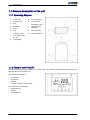
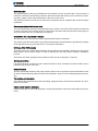
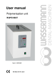
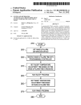
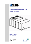
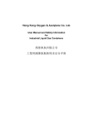
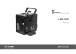
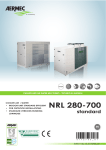
VITALITY LARGE SPLIT AIR ‑ AIR
Air conditionating units
User manual
Ref.: N-40340_EN 0210
Index
Index
1
User manual............................................................................................................................ 1
1.1
1.1.1
1.1.2
1.1.3
1.1.4
1.1.5
General description of the unit ..............................................................................................
Operating diagram..................................................................................................................
Parts of the VITALITY............................................................................................................
Description of the unit.............................................................................................................
YKN2 Open Control Circuit....................................................................................................
Service and Maintenance Access..........................................................................................
1.2
1.3
1.4
1.4.1
1.4.2
1.4.3
1.5
1.5.1
1.5.2
1.6
1.7
1.7.1
1.7.2
1.7.3
1.7.4
1.7.5
1.8
1.8.1
1.8.2
Intended use of the unit.......................................................................................................... 6
Description of the unit's main control panel............................................................................ 7
Modes of operation................................................................................................................ 7
VAC models: air conditioning................................................................................................. 7
VAH models: heat pump........................................................................................................ 7
General instructions............................................................................................................... 8
Operating instructions............................................................................................................ 8
Thermostat connections to the control board......................................................................... 8
Thermostat connections......................................................................................................... 9
Safety and equipment protection systems............................................................................. 9
Placing the unit out of service for planned stoppage or malfunction ................................... 10
Placing the unit out of service for planned stoppage............................................................ 10
Placing the unit out of service for seasonal stoppage.......................................................... 10
Placing the unit out of service due to a fault......................................................................... 10
Fault codes for the air conditioning unit................................................................................ 10
Restarting the air conditioning unit in the case of breakdown.............................................. 11
Regular maintenance by the user ....................................................................................... 11
Maintenance Schedule......................................................................................................... 11
Maintenance responsibilities of the user.............................................................................. 12
2
2
2
4
6
6
i
1
User manual
1
1.1
User manual
General description of the unit
1.1 General description of the unit
1.1.1 Operating diagram
1.
Indoor unit
A.
Air from indoors
2.
Outdoor unit
B.
Air to indoors
3.
Fan
4.
Axial fan
C.
5.
Filter
Possibility of air to
vertical indoors
(optional)
6.
Coil
D.
Air to outdoors
E.
Air from outdoors
7.
Optional: water
coil, electric resis‐
tor, etc.
8.
Compressor
1.1.2 Parts of the VITALITY
The VITALITY series range is made up of a series of air ‑ air units with centrifugal fans in the indoor unit
and axial fans in the outdoor unit.
The outdoor unit includes:
•
•
•
•
Compressor.
Condenser.
Axial fan.
Controls and DPC-1 thermostat.
The VIR indoor unit includes:
•
•
•
2
Evaporator coil.
Air filter.
Centrifugal fan.
User manual
General description of the unit
1
1.1
The unit can be located indoors or outdoors, as it is protected to withstand outdoor weather conditions.
The units is supplied fully fitted and factory-tested and is designed to provide a significant saving of
energy and a long working life.
The air intakes and outlets on each VIR model can be configured vertically or horizontally (using the
optional kit).
Software installed on the YKN2 Open electronic board provides electronic management for the YKN2
Open control board.
In addition, a wide range of accessories is available to adapt the units to the specific requirements of
each application. The VITALITY series air conditioning units can be used in extreme weather conditions.
3
1
1.1
User manual
General description of the unit
1.1.3 Description of the unit
Compressors
type compressors with internal motor protection and external sump resistor included as standard, which
keeps the oil hot for easier start-up and to prevent its drag outside the compressor. They are charged
with a POE (polyol-ester) oil to avoid the formation of foam.
VAC-VAH 20A, 25A, 30A and 40A units have just one compressor and VAC-VAH 45A, 60A, 75A and
90A units have two compressors with two independent circuits.
The compressors have been specifically designed for units with heat pumps: their mechanical compo‐
nents are large and their motors have a lower current consumption.
The compressors have dampers to reduce operating noise and vibrations.
Based on the accumulated operating hours of each compressor, a control circuit determines the order
of operation, thus lengthening their working life.
Suction accumulator (models with heat pump only)
Connected to the compressor suction pipe, this protects it from hammering by liquid.
Coils
These are large and made of copper tubes and aluminium fins. They are located inside the unit, protected
against knocks during transportation and installation.
To adapt the product perfectly to its environment, there are options such as coils with Blue-Fintype fins
or copper fins.
Indoor fan (on VIR 25A model only)
A centrifugal fan driven by an independent motor and with belt transmission is installed in the VIR 25A
model.
Indoor fan (models VIR 40A, 45A, 60A, 75A and 90A)
One, two or four centrifugal fans with a joint shaft, driven by an independent motor and connected to a
single plenum are installed in the models indicated.
Outdoor fan (VAC-VAH models)
One, two or four axial fans with free discharge, no ducts and low operating noise levels are installed in
the models indicated.
Optionally, a summer cycle operating speed adjuster can be fitted that is adjusted by the high pressure
of the cooling circuit.
Cooling circuit
The cooling circuit is made of welded copper pipes and includes access connections on the high and
low-pressure sides. It is fitted with shut off valves on the suction side that are used in the factory to protect
the compressor during the 45 bar pressure test that all units must pass.
The VAC-VAH and VIR units are supplied with pre-connections for welding.
Refrigerant
The gas refrigerant must be fully charged during on-site installation.
The entire range of units uses environment-friendly, recyclable R-410A gas refrigerant.
Cooling circuit protection
All cooling circuits are supplied as standard with high and low-pressure switches, dehydrator filter on the
liquid line, discharge temperature cut-out switch, liquid sight glasses and temperature sensors for supply
air, suction liquid and outdoor air.
4
User manual
General description of the unit
1
1.1
Electrical panel
The electrical panel is directly accessible from the outside by means of a panel with 1/4 turn closures. It
includes a connection terminal strip, protectors, electronic boards and sensors, power contactors, switch‐
ing relays, phase control relay and transfer for the 24V control circuit.
The electrical panel for the unit has an IP44 level of protection and is compliant with current European
regulations.
Sequence and phase fault sensor relay
The unit is fitted with a sequence and phase fault sensor: where a non R-S-T phase sequence is detected
or where, once the unit is running, there is a phase fault, the sensor will disconnect the power supply to
the main board of the unit, preventing it from starting.
Construction and rust protection features
All metal parts of the structure are made of galvanised aluminium steel plate.
The outdoor parts are treated with oven-polymerised polyester paint (RAL9002), guaranteeing a quality
finish that lasts for many years (800 H.N.S. according to DIN 50021).
Unit base (VAC-VAH models)
The base of the unit is made with fixed beams that provide a solid foundation. Openings on the front of
these beams can be used to attach a crane for hoisting the unit into position during the installation
process.
The beams also have openings on the bottom to place the unit on dampers, if required.
Service connections
For easier electricity connections with a minimal amount of work, electrical and control cables can be
pulled through the front of the unit.
Noise emissions
All units operate with extremely low noise emission levels. The compressors have anti-vibration mounts
as well as vertical discharge fans that direct noise upwards, away from surrounding buildings and prop‐
erty.
Thermal/Acoustic Insulation
The inside of the evaporator area and the heating supply/accessory area are fully insulated. The insu‐
lation is 5 mm thick.
Indoor electric resistors (Optional)
Exposed cord-type for fast heat dissipation, avoiding temperature inertia that could affect the compo‐
nents.
5
1
1.2
User manual
Intended use of the unit
1.1.4 YKN2 Open Control Circuit
YKN2 Open YKN2 Open control board
The control circuit is 24 V and can operate with the
standard DPC-1 thermostat (communication) or with
a 24 V thermostat with control signals (Y1, G, O/B,
W).
A YKtoolsystem analyser can be used for easier startup and to locate and solve any installation or operat‐
ing faults.
1.1.5 Service and Maintenance Access
The units are fitted with access panels with 1/4 turn closures on the control panel and levers offering fast,
safe access to all components requiring service or maintenance.
Access to the control circuit is independent to the cooling system of the unit.
The unit is fitted with connections for specific manometers for easier reading of cooling circuit pressures.
1.2 Intended use of the unit
The VITALITY series of units is exclusively designed for the air conditioning of buildings and properties.
Therefore, the unit has a cold generating system, a heat pump and, as optional, auxiliary electrical re‐
sistors and hot water coil. Depending on the version that forces air to circulate through ducts to adjust
the temperature of the building or property where it is installed. The air conditioning unit has a start-up
and setting mechanism (by means of a thermostat) to manage its operations.
The unit should only be used for the purposes for which it was designed and built. Johnson Controls Inc.
shall not be considered responsible for any damage caused by inappropriate use or maintenance of the
unit that is any way inconsistent with that described in this document or others specifically provided with
the unit.
Any use other than air conditioning will be considered inconsistent.
6
User manual
Description of the unit's main control panel
1
1.3
1.3 Description of the unit's main control panel
The main control panel is found on the unit itself and
is protected from the outside by a removable metal
panel.
1 Connection entry.
2 Grommet support tray.
Given that the air conditioning unit is installed on the
roof of a building or property, users must under no
circumstances inspect or adjust the unit themselves.
All of inspections or adjustments that may be made
by the user are performed using the DPC-1 thermo‐
stat.
If the air conditioning unit is faulty, its self-diagnostics
system will identify the source and the pilot light -1on the display of the DPC-1 thermostat will switch on.
The display will also show a two-digit number on the
lower left -2-, indicating the effected component.
See Placing the unit out of service due to a fault , see
on page 10 .
If the thermostat display keeps showing the pilot light
-1- and any fault code or if the air conditioner does not
start, contact a Johnson Controls Inc. Authorised
Technical Assistance Service.
1.4 Modes of operation
The VITALITY range of air conditioning units includes different models: the operating mode for each one
varies depending on the specific model.
1.4.1 VAC models: air conditioning
The VAC model circulates gas refrigerant (R-410A) through a cooling circuit driven by two compressors
(depending on models). The propelled gas circulates through an evaporator coil where it absorbs ambient
heat and evaporates. To liquefy the evaporated gas, it is then circulated through a condenser coil where
it releases the previously absorbed heat into the atmosphere.
To favour the evaporation and condensation of the gas refrigerant, the unit has supply and intake fans
that force the air through each of the coils. In the case of the evaporator, the fan pushes air to the inside
of the building or property through previously-installed distribution ducts. In the case of the condenser,
the fan pushes fresh air through the coil and then sends it back outdoors.
A series of filters remove dust particles and pollen, etc. from the air sent inside the building or property.
1.4.2 VAH models: heat pump
The VAH models operate the same way as the VAC units, although they can also reverse the cooling
circuit operation so that the coils exchange functions and send warm air to the inside of the building or
property and the cold air outdoors.
7
1
1.5
User manual
Operating instructions
1.4.3 General instructions
CAUTION
Always keep the electrical power supply connected to the unit.
Only disconnect the unit if it is not to be used for a long period of time.
When preparing for seasonal use, connect the unit to the electricity supply at least 8 hours before
starting it.
•
•
•
False start the compressors (connect them just long
enough to make a few turns). To do so, use contactors
-KM1- and -KM2-.
Wait for 5 to 7 minutes and repeat the false start.
Wait another 5 to 7 minutes and perform a last false
start.
Then switch the compressors to full working order.
1.5 Operating instructions
A thermostat is used for starting and managing the air conditioning unit and for adjusting the temperature
of the supply air.
Through this thermostat, the operating programme determines when to automatically start the air con‐
ditioning unit. The performance of the different unit components is also determined by the operating
programme.
See the documents on the DPC-1 programmable digital thermostat with communication or the documents
on the thermostat installed with the unit for further details on the start-up and adjustment mechanism.
1.5.1 Thermostat connections to the control board
A. Thermostat connection board.
Board connection terminals
X1. To terminal X1 of the DPC-1 thermostat.
B.
White To terminal B of the DPC-1 thermostat.
R.
Red. To terminal R of the DPC-1 thermostat.
W.
–
O/B –
Y1
8
–
User manual
Safety and equipment protection systems
1
1.6
1.5.2 Thermostat connections
1.
Yellow cable.
2.
Red cable.
3.
White cable.
A.
Shielded cable, 2 x 0.5 mm2. Maximum length:
100 m.
B.
Shielded cable, 10 x 0.22 mm2. Maximum
length: 100 m.
1.6 Safety and equipment protection systems
The VITALITY range of air conditioning units includes an entire series of safety and protection systems
intended to provide a high degree of safety for users and maintenance personnel.
Those not expressly authorised to use the air conditioning unit must not handle it or perform repair or
maintenance work.
Safety systems
Johnson Controls Inc. manufactures air conditioning units in accordance with EU occupational protection
and user safety regulations, provided that the units are used and maintained in line with the instructions
and indications given in this document.
Given that the air conditioning unit is installed on the roof of a building or property, users must under no
circumstances inspect or adjust the unit themselves. All of inspections or adjustments that may be made
by the user are performed using the DPC-1 thermostat.
The air conditioning unit is fitted with electrical protection systems to protect personnel responsible for
its regular maintenance and upkeep.
As established by applicable electricity regulations, the electrical system is fitted with electricity surge
and current leakage protection system consisting of differential circuit breakers and thermal magnetic
switches (not supplied by the manufacturer, must be installed on site).
Under no circumstances is the user of the air conditioning unit exposed to live parts.
Likewise, access to moving parts by unauthorised persons is prevented. This involves placing appropri‐
ate safety locks on all of the removable covers on the unit.
Unit protection systems
The refrigerant circuit of the unit is protected against excessively high or low pressure and discharge
temperature. It is also protected against repeated cold start-ups caused by the compressor intake sensor
when the summer cycle is activated.
9
1
1.7
User manual
Placing the unit out of service for planned stoppage or malfunction
1.7 Placing the unit out of service for planned stoppage or mal‐
function
1.7.1 Placing the unit out of service for planned stoppage
To stop the air conditioning unit using the DPC-1 ther‐
mostat, press the MODE, -1- key repeatedly until the
following appears: OFF, -2-.
1.7.2 Placing the unit out of service for seasonal stoppage
The power supply to the unit must be disconnected when placing the air conditioning unit out of service
for long periods of time (seasonal stoppage).
To do so, the differential circuit breaker and thermal magnetic switch on the unit power supply must be
disconnected.
•
•
•
CAUTION
Always keep the electrical power supply connected to the unit.
Only disconnect the unit if it is not to be used for a long period of time.
When preparing for seasonal use, connect the unit to the electricity supply at least 8 hours before
starting it.
1.7.3 Placing the unit out of service due to a fault
If the air conditioning unit is faulty, its self-diagnostics
system will identify the source and the pilot light -1on the display of the DPC-1 thermostat will switch on.
The display will also show a two-digit number on the
lower left -2-indicating the effected component.
1.7.4 Fault codes for the air conditioning unit
Code
10
Description
11 / 21 / 31
Discharge temperature exceeded
12 / 22 / 32
High-pressure switch, outdoor fan thermal switch or compressor module ther‐
mal switch (depending on model)
User manual
Regular maintenance by the user
Code
13 / 23 / 33
14
15 / 25 / 35
•
•
1
1.8
Description
Low pressure switch
Indoor fan thermal switch
Repeated cold start-up or suction temperature < ‑25 °C
41
Gas control 1 or resistor 1 fault
42
Gas control 2 or resistor 2 fault
43
Resistor stage 3 fault
44
Resistor stage 4 fault
45
Fault in economiser or hot water coil (outdoor supply, water return sensor)
46
Smoke detector, high temperature, or supply temperature >80 ºC
91
Ambient sensor open or short circuited
92
Internal sensor not calibrated
93
Communication error
94
fault with AL terminal connected
95
S5 digital sensor not detected
96
S6 digital sensor not detected
97
S7 digital sensor not detected
98
S8 digital sensor not detected
99
Digital outdoor sensor not detected
NOTE
The fault pilot light on the DPC-1 thermostat display will flash if a fault code between 0 and 90 is
shown.
The fault pilot light on the DPC-1 thermostat display will also flash if fault code 93 is shown.
1.7.5 Restarting the air conditioning unit in the case of breakdown
If you have to restart the unit it is possible by pressing the MODE key on the thermostat repeatedly until
the display indicates OFF.
Then, restart the unit by pressing the MODE key and select the required operating mode.
The unit will start up normally if the cause of the fault is no longer present. If the cause persists, it is
possible to start the unit a maximum of three times within a 24-hour period.
If the thermostat display keeps showing the pilot light -1- and any fault code or if the air conditioner does
not start, contact a Johnson Controls Inc. Authorised Technical Assistance Service.
1.8 Regular maintenance by the user
1.8.1 Maintenance Schedule
The air conditioning unit is designed to require as little maintenance as possible. Nevertheless, to ensure
smooth operations with a minimal use of electricity, a long working life and compliance with the regula‐
tions of each country, regular maintenance inspections must be made.
Johnson Controls Inc. shall not be considered responsible for any damage caused by improper mainte‐
nance of the unit, which includes anything inconsistent with that described in this document or others
specifically provided with the unit.
To make them easier, maintenance tasks have been grouped by time intervals in a series of tables.
Maintenance responsibilities of the user , see on page 12 .
11
1
1.8
User manual
Regular maintenance by the user
1.8.2 Maintenance responsibilities of the user
Like any other machine, the air conditioning unit requires regular maintenance, as the wear to which
some of its parts are subjected can effect its mechanical reliability and the safety of those responsible
for its maintenance.
In compliance with current regulations, the unit must be regularly inspected and the results recorded on
the forms provided by the Labour and Health Authorities of the country where the air conditioning unit is
installed.
Users cannot access this form to perform maintenance and upkeep tasks on the unit.
There is no intent for the user to perform any maintenance tasks on the air conditioning unit.
DANGER
It is strictly prohibited for the user to carry out any maintenance or upkeep tasks on the air conditioning
unit.
Only trained Johnson Controls Inc. personnel with the necessary means and tools may carry out main‐
tenance and upkeep work on the unit.
Trained personnel must be aware of the health and safety regulations and procedures applicable to air
conditioning units. They should also be aware of general procedures and those applying specifically to
this unit.
Contact a Johnson Controls Inc. Authorised Technical Assistance Service for scheduled maintenance
on this unit.
To discover the maintenance operations a Johnson Controls Inc. Authorised Technical Assistance Serv‐
ice should regularly perform, see Maintenance Schedule , see on page 11 .
PRODUCT DISPOSAL
According to Directive 2002/96/EC of the European
Parliament and of the Council of 27 January 2003, the
presence of the symbol on the product or in the docu‐
ments included with the product indicates that this
product is classified, according to current law, as an
electrical and electronic device and, therefore, this
product cannot be dealt with at the end of its working
life as domestic or urban waste.
The product must be taken to collection points for the
recycling of waste electrical and electronic equip‐
ment.
The appropriate management, reuse, assessment
and recycling of these products protect human health
and the environment.
12