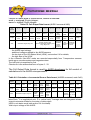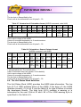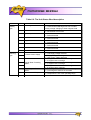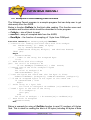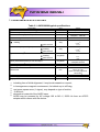
1
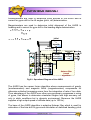
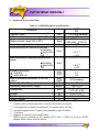
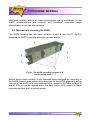
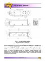
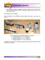
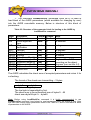
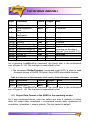
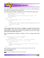
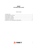
Attitude and Heading Reference System AHRS M2, M2-M User’s Manual March, 2009 Revision 3.0 Revision history Revisio Date n 1.0 14-Jun-07 1.1 to 2.6 3.0 20-Mar-09 Author Description ON Released version. Skipped For AHRS firmware since v.4.1.7. Updated output data formats (see item 6.3). Realized AHRS initial alignment at slow rocking object for marine applications (option). ON Table of contents 1. Introduction..................................................................................................5 1.1. Description of the System................................................….....................5 1.2. Package Contents....................................................................................6 2. AHRS operation principles..........................................................................7 2.1. Description of the AHRS orientation angles.............................................7 2.2. Principles of the AHRS Operation............................................................8 3. AHRS Specifications.................................................................................11 4. Installation.................................................................................................12 4.1. Where to install the AHRS for tests........................................................12 4.2. Where to install the AHRS on the object................................................13 4.3. Mechanically mounting the AHRS..........................................................14 4.4. Variants of the AHRS mounting relative to the object axes....................16 5. Electrical connections................................................................................18 5.1. Cable and Connectors............................................................................18 5.2. Quick Electrical Connections for the AHRS Evaluation..........................21 6. Software interface......................................................................................22 6.1. Operational Modes of the AHRS and Data Formats...............................22 6.2. Executive Instructions for the AHRS.......................................................23 6.3. Output Data Format of the AHRS in the operating modes.....................26 6.4. The Unit Status Word definition..............................................................29 6.5. Examples of Data Reading from the AHRS............................................31 7. AHRS Demo Program...............................................................................33 8. Warranty....................................................................................................34 9. description of AHRS M2-M........................................................................35 10. Peculiarity of the marine AHRS operation...............................................36 11. AHRS M2-M specifications.....................................................................37 12. AHRS Demo Program.............................................................................38 LIST OF FIGURES Figure 1.1. The AHRS .....................................................................................5 Figure 1.2. Data Cables Set ............................................................................6 Figure 1.3. Protective tube...............................................................................7 Figure 1.4. AC/DC adapter with interchangeable plug ....................................7 Figure 2.1. AHRS with body-fixed coordinate system .....................................7 Figure 2.2. Operational Diagram of the AHRS ................................................9 Figure 4.1. The AHRS mounting surfaces A, B and mounting holes 1 – 7....14 Figure 4.2. The AHRS outline drawing .........................................................15 Figure 4.3. Examples of the AHRS mounting on the object...........................17 Figure 5.1. 5-Pin connector male pinout ......................................................18 Figure 5.2. The diagram of electric connection of the AHRS to host computer .......................................................................................................19 Figure 5.3. The diagram of the interface cable 1 for the AHRS connections to the СОМ-port of host computer and to the AC/DC adapter ..........................20 Figure 5.4. The view of plug connectors of the interface cable 1 ..................20 Figure 5.5. AHRS light indicator ....................................................................21 Figure 8.1. Location of the seals on the AHRS..............................................34 LIST OF TABLES Тable 3.1. AHRS M2 typical specifications ...................................................11 Тable 5.1. Pin diagram of the AHRS connector.............................................18 Table 5.2. Electrical specification ..................................................................18 Table 6.1. СОМ-port parameters ..................................................................22 Тable 6.2. Structure of the parameter block for loading to the AHRS by LoadBlockPar command..........................................................................25 Тable 6.3. Structure of the parameter block read by ReadBlockPar command ......................................................................................................26 Тable 6.4. Structure of the parameter block read by GetVerFirmware command ......................................................................................................26 Тable 6.5. Full Output Data format (at AHRS1 command) ............................27 Тable 6.6. Orientation + Incremental Sensor Data format (at AHRS2 command) .....................................................................................................27 Тable 6.7. Quaternion of Orientation format (at AHRS3 command) .............28 Тable 6.8. Orientation + Sensor Outputs format (at AHRS4 command) ...................................................................................28 Table 6.9. The Unit Status Word description.................................................29 Table 7.1. The recommended requirements for the PC configuration...........33 1. INTRODUCTION 1.1. Description of the System The AHRS (Attitude and Heading Reference System) is designed for measuring Euler orientation angles (heading, pitch and roll) in static and dynamic environment. It consists of three gyros, three accelerometers, three magnetometers with internal power regulations and embedded microcomputer. Original algorithm is used for above sensors signal processing to achieve high accuracy of attitude and heading determination. The AHRS is a high-speed digital output orientation measuring system. It can transmit the orientation angles (heading, pitch and roll) of a body which it is mounted to at a rate of up to 100 samples/second. Data transmissions are made over a bi-directional serial port using either RS-232 or USB (via COMto-USB converter). Sampling rate is selected by user from 1 Hz to 100 Hz (default setting). Fig.1.1. The AHRS 1.2. Package Contents In addition to your AHRS product you should have: • 1 Data Cables Set. It consists of (see Fig.1.2): - cable 1 provides electrical connection between the AHRS and an external receiving device through a СОМ port and power supply; - COM-to-USB converter FTDI FT232BM provides connection with an external receiving device via a USB port; • 1 Protective Tube (optional). This tube (see Fig.1.3) can be screwed on the AHRS connector to protect it from the external mechanical damage. • 1 interchangeable AC/DC Adapter. The two AC plugs are possible: USA and EUR. The adapter is used for the AHRS powering from 110-240V, 50-60Hz AC power source (see Fig.1.4). • 1 miniCD with AHRS Software. This software allows you immediately to view the outputs of the AHRS on a PC running Microsoft® Windows™ and save measured data on a PC hard disk. • 1 User’s Manual. It contains useful information about mounting and connecting of the AHRS, and usage of enclosed demo software for viewing and saving of the AHRS output data. • 1 Demo Program “AHRS DEMO” User’s Manual. It contains useful information about installing and usage of enclosed demo software for visualization of the AHRS orientation angles and saving of the AHRS output data. Cable 1 COM-to-USB converter Fig.1.2. Data Cables Set Fig.1.3. Protective tube Fig.1.4. AC/DC adapter with interchangeable plug 2. AHRS OPERATION PRINCIPLES 2.1. Description of the AHRS orientation angles Fig.2.1 shows the AHRS’ own coordinate system Oxoyozo. This coordinate system is a body-fixed and defined as the calibrated sensors coordinate system. Non-orthogonality between the axes of the body-fixed coordinate system Oxoyozo is less then 0.01°. Fig.2.1. AHRS with body-fixed coordinate system The roll angle of the AHRS is zero when the X-axis is oriented horizontally and Z-axis is in upper half-sphere. If X-axis is horizontal and Z-axis is in lower half-sphere, then roll angle is equal to 180°. If Z-axis is oriented horizontally and X-axis is in lower half-sphere, then roll angle is equal to +90°. The pitch angle of the AHRS is defined as 0° when the Z-axis is pointed up or down. If Y-axis is pointed up, then pitch angle is equal to +90°. If Y-axis is pointed down, then pitch angle is equal to –90°. The heading angle of the AHRS is referenced to magnetic North and is zero when the projection of the AHRS Y-axis on a horizontal plane is oriented North. If the projection of Y-axis on a horizontal plane is oriented East, then heading angle is equal to +90°. Thus heading is positive for clockwise rotation around the vertical axis. Measured angles are the standard Euler angles to rotate from the earth-level frame (East-North-Up) to the body frame, heading first, then pitch, and then roll. Orientation angles, measured by the AHRS, are not limited and are within common ranges: • Heading 0…360°; • Pitch ±90°; • Roll ±180°. 2.2. Principles of the AHRS Operation The AHRS is designed for measuring Euler orientation angles (heading, pitch and roll) of an object in static and dynamic environment. The AHRS is a measurement system that consists of three gyroscopes, three accelerometers and three magnetometers. All sensor axes are aligned with the AHRS axes. Using 3-axis gyro, accelerometer and magnetometer units allows making a complete measurement of an object orientation angles. The operational diagram of the AHRS is shown in Fig.2.2. The AHRS uses gyros to measure absolute angular rate of the carrier, then its orientation angles (heading, pitch and roll) are obtained by using special integration of gyros outputs. Accelerometers are used to determine initial attitude of the AHRS and to correct for gyros drift in the tilt angles (pitch, roll) determination. Magnetometers are used to determine initial alignment of the AHRS in heading and to correct for gyro drift in the heading angle determination. A c c G el yr er os o m et er s M a g n et o m et e r s Initial alignmen t algorith m Initial G y0 Gz G x 0 0 Ay 0 Ax Az 0 M0 y0 rx ry o rz o o ax ay o a z o m o x my o mz o M z0 M x0 o conditions Numeric integrating of the orientation equations Orientati Heading on H Pitch angles P estimati Roll R on rxc ryc rzc Computati on of correction signals Kalman filter based algorithm Fig.2.2. Operational Diagram of the AHRS The AHRS has the sensor fusion algorithm where measurements of gravity (accelerometers) and magnetic North (magnetometers) compensate for otherwise unlimited increasing errors from the integration of rate of turn data. Thus advantage of the AHRS over other non-gyroscopic compasses is using of gyros, that allows to determine orientation angles with high accuracy not only in static conditions but in dynamic environment. Moreover the AHRS supplies a high output speed of attitude data (up to 100 Hz). The base of the AHRS algorithm is adaptive Kalman filter which is used for estimation of the bias drift of gyros and calculation of stabilized heading, pitch and roll angles. The Kalman filter automatically adjusts for changing dynamic conditions without any external user input. After start the AHRS it requires about 60 seconds for initial alignment process. At this initial orientation angles are determined as initial conditions for integration of gyros outputs. Also gyros drift is estimated using Kalman filter for next compensation. Therefore don’t move the AHRS during initial alignment process. If this requirement is not met then large errors may be occurred in orientation angles determination. As the AHRS uses magnetic sensors for heading reference, then it directly determines just magnetic heading. The AHRS can also provide true North heading when the current magnetic declination is given. Declination, also called magnetic variation, is the difference between true and magnetic North, relative to a point on the Earth. Declination angles vary throughout the world, and change very slowly over time. Declination angle can be entered directly in the AHRS memory using special command (see Table 6.2 in item 6.2). For this the declination angle should be known or calculated using AHRS software (see “AHRS Demo Program” User’s Manual, section 4. Options menu). By additional information about latitude, longitude, altitude and date, the AHRS Demo software calculates the declination using the World Magnetic Model produced by the U.S. National Geophysical Data Center and the British Geological Survey (http://www.ngdc.noaa.gov/geomag/WMM/DoDWMM.shtml). The World Magnetic Model is the standard model of the US Department of Defense, the UK Ministry of Defense, the North Atlantic Treaty Organization (NATO), and the World Hydrographic Office (WHO) navigation and attitude/heading referencing systems. 3. AHRS SPECIFICATIONS Тable 3.1. AHRS M2 typical specifications Parameter Update Rate Full accuracy data (warm-up time) (1) Measurement range (full in 3D) Maximum angular rate Static accuracy at normal conditions • heading • pitch and roll Static accuracy in operating temperature range • heading • pitch and roll (3) Dynamic accuracy • heading • pitch and roll Noise (standard deviation) at 100 Hz output Sensors bandwidth (4) Operating temperature range Dimensions Weight Power supply: Supply current AHRS M2 Hz 1...100 (user settable) sec 60 0...360 heading deg ±90 pitch; ±180 roll deg/sec ±300 Unit deg < 0.3 (2) < 0.1 deg < 0.5 (2) < 0.3 deg RMS deg RMS Hz deg C mm kg V DC A 0.7 0.4 0.03 heading 40 -40 to +70 109 x 31 x 29 (case) 127 x 31 x 29 0.19 / 0.16 (5) +5.5 to +6.5 (6) 0.11 (1) including time of initial alignment, it may be decreased on request; (2) in homogeneous magnetic environment, for latitude up to ±65 deg; (3) root mean square error (1 sigma), may depend on type of motion; -3 dB level; depends on material of the AHRS case; AHRS may be powered by AC voltage 100 to 240 V, 50/60 Hz from an AC/DC adapter which comes with the device. (4) (5) (6) 4. INSTALLATION This section describes how to mount the AHRS into your system and make electrical connections. To install the AHRS into your system, follow these steps: • choose a mounting location; • mechanically mount the AHRS; • make electrical connections to the AHRS; • evaluate the AHRS using the included "AHRS_Demo" Program. 4.1. Where to install the AHRS for tests The AHRS has magnetometers with wide dynamic range and its sophisticated calibration algorithms allow it to operate in many environments. For optimal performance however, you should mount the AHRS with the following considerations in mind. • Locate the AHRS away from local sources of magnetic fields The place for testing must not have ferromagnetic (magneto-susceptible) materials and the lab room itself must have the level of intrinsic magnetic and electro-magnetic fields suitable for the magnetic heading system testing: - inside and near the lab room there must be no powerful source of magnetic, electrical and electro-magnetic fields. The magnetic field intensity must not be different from the Earth magnetic field intensity at the test site more than 0.01%; - small ferromagnetic objects must be as far as 3 meters from the test table. Large size ferromagnetic objects such as cars and trucks must be as far as 15 m from the table; - it is necessary to conduct a regular check-up of the magnetic field uniformity inside the lab room. It is highly recommended to degauss AHRS before heading test to remove permanent magnetization of some components in the AHRS (if you accidentally expose the unit to a large magnetic field). You can use a handheld demagnetizer (tape eraser) to demagnetize the AHRS. Most audio and video degaussing units can be used. Follow the instructions for your demagnetizer. • The AHRS should be mounted in a physically stable location Choose a location that is isolated from excessive shock, oscillation, and vibration. Special rotary table must be used for the AHRS accuracy testing, that mounted on a special testing basement which is free from the laboratory oscillations and vibrations. Tests on vibrations and shocks are fulfilled separately from the main accuracy tests. 4.2. Where to install the AHRS on the object It is necessary to follow the recommendations listed in it.4.1. whenever it is possible, when installing the AHRS on an object. • AHRS should be installed on an object as far as possible from large ferromagnetic masses of the object and powerful sources of magnetic, electrical and electro-magnetic fields If the residual effects of ferromagnetic masses of the object distort the Earth magnetic field to no more than 20%, AHRS software allows compensation of influence of the carrier object soft and hard iron on the heading angle determination accuracy. For this purpose, field calibration of the AHRS magnetometers is provided. This calibration does not require any additional equipment, but it requires turns of the carrier object, on which the AHRS is mounted. Note that the above field calibration remains active until the residual magnetic field of the object surrounding the AHRS is changed. If this field is changed due to displacement of ferromagnetic masses of the object or magnetic field sources, the AHRS should be re-calibrated. Field calibration procedure is described in User’s Manual on the HRS Demo Program. Field calibration procedure is developed by after type of the object, on which the AHRS will be used, is agreed on with a customer. • It is preferable to locate the AHRS as close to the centre of mass of the object as possible With such location, effects of linear accelerations during oscillations on the AHRS accelerometers are reduced, and therefore, orientation angle determination errors are also reduced. 4.3. Mechanically mounting the AHRS The AHRS housing has two base surfaces A and B (see fig.4.1, fig.4.2) designed for AHRS mounting during its run and testing. Fig.4.1. The AHRS mounting surfaces A, B and mounting holes 1 – 7 Salient bottom base surface А has threaded holes designed for mounting of the AHRS. Lateral base surface B is designed for the AHRS alignment during mounting. The AHRS is factory calibrated with respect to the base surfaces A and B, thus it must be aligned within the host system with respect to these mounting surface, not the device edges. Fig.4.2. The AHRS outline drawing (all dimensions are in millimeters) When mounting AHRS on your system, please pay attention to orientation of input axes X", "Y", "Z" (Fig.2.1) – respective marking is engraved on the cover of the AHRS. During the ordinary operation on the carrier object the AHRS is set on the surface A with the axis Y directed on the nose of the object. To obtain accurate attitude and heading, please remember that mounting is very important and mounting error can cause attitude and heading errors. When AHRS mounting please align it on two base surfaces relative your system axes. There are two variants of the AHRS mounting on your system: 1) Use 4 threaded holes M2x5 mm on the bottom of AHRS (see Fig.4.1, positions 1 – 4). 2) Use 3 holes ∅2.5 mm on 3 lugs (see Fig.4.1, positions 5 – 7). Note: For the AHRS with aluminum case it is not recommended to use threaded holes (see Fig.4.2, positions 1 – 4) for mounting the AHRS because of possible damage of these threads. Requirements to the mounting surface of the carrier object: flatness tolerance is 0.03 mm; undulation is Ra=1.25. 4.4. Variants of the AHRS mounting relative to the object axes Since firmware version 3.3.9 the AHRS can be mounted on the object in any known position (up to upside-down, upright etc.) relative to the object axes. Such mounting doesn’t change right determination of the object orientation if angles of the AHRS mounting are correctly stored in the AHRS nonvolatile memory. To store angles of mounting in the AHRS please use the AHRS Demo Program (item «Device option …» from the «Options» menu) or send LoadBlockPar command to the AHRS directly (see structure of the LoadBlockPar command in the Table 6.2 below). Angles of the AHRS position (alignment angles) are set in next order (like heading, pitch and roll setting): first alignment angle sets position of the AHRS longitudinal axis Y relative to longitudinal axes of the object measured in the horizontal plane of the object. Clockwise rotation is positive; second alignment angle is equal to angle of inclination of the AHRS longitudinal axis Y relative to the horizontal plane of the object. Positive direction is up; third alignment angle is equal to inclination angle of the AHRS lateral axis X measured around AHRS’s longitudinal axis. Positive rotation is X axis moving down. All angles are set in degrees. Some examples of the AHRS mounting relative the object are shown on Fig.4.3. y z x b c d y y z a x x z z x y Fig.4.3. Examples of the AHRS mounting on the object a – alignment angles are 0, 0, 0 (degrees); b – alignment angles are 0, 0, 180 (degrees); c – alignment angles are 90, 0, 0 (degrees); d – alignment angles are 0, -90, 180 (degrees); To check correctness of the alignment angles please run the AHRS using the AHRS Demo Program. 5. ELECTRICAL CONNECTIONS 5.1. Cable and Connectors The AHRS has 5-Pin connector Binder 719 09-9789-71-05 (Male) for electrical connection to host system. Fig.5.1 shows the AHRS connector pinout. 1 5 2 3 4 Fig.5.1. 5-Pin Connector Male Pinout (view from the AHRS connector) Тable 5.1. Pin diagram of the AHRS connector Pin 1 2 3 4 5 Signal RxPC GND TxPC VDD not used Тable 5.2. Electrical specifications Parameter Input Supply Current Power Conditions VDD = +6V VDD = +6V Min +5.5V Typical +6V 110 660 Max +6.5V Units Volts DC mA mW For the AHRS power supply the outer AC/DC adapter also can be used which receives the power from the 100…240V 50…60Hz AC power source. AC/DC power adapter is included in the delivery set. The set of components for the AHRS electrical connection includes: - AHRS; - interface cable 1 for the AHRS connection to the СОМ-port of IBM PC or another device, with branch wires for the AHRS DC powering; - AC/DC adapter. Fig.5.2 shows diagram of electric connection of the AHRS to host computer (IBM PC). The AHRS exchanges the information with host computer through the СОМ-port. X1 Innalabs AHRS 5 Cable 1 X3 9 СОМ Host Computer 100÷ 240 V 50 ÷ 60Hz Power Block 100÷ 240V/ +6V X2 2 AC/DC Adapter Fig.5.2. The diagram of electric connection of the AHRS to host computer Fig.5.3 shows the diagram of the interface cable 1 for the AHRS connections to the СОМ-port of host computer and to the DC power source. Fig.5.4 shows pinouts of the interface cable 1 connectors. Х1 5 Х3 9 Х2 2 Х 3 ( СОМ) – Female c onnector DB-9F i n the case Х1 – Female connector Binder 719 09- 9790-71-05 1 DCD RxPC 1 2 Rx TxPC 3 3 Tx GND 2 4 DTR VDD 4 5 SG 5 6 DSR 7 RTS 8 CTR 9 RI Х2 ( Power) GND VDD Fig.5.3. The diagram of the interface cable 1 for the AHRS connections to the СОМport of host computer and to the AC/DC adapter Х1 Х2 Vdd 5 1 4 3 2 GND Fig.5.4. The view of plug connectors of the interface cable 1 5.2. Quick Electrical Connections for the AHRS Evaluation To test the AHRS provide the working place as it is shown in Fig.5.2. 11 Connect cable 1 to the AHRS and to a PC СОМ port. Connection of the cable 1 to the AHRS is done through the Binder 719 09-9789-71-05 (Male) connector on the AHRS case. 11 Connect cable 1 to the AC/DC network adapter. 11 Apply power to the AHRS; for this, connect the network adapter to the mains. Start-up time for the device is not more than 2 seconds. Red light of the indicator lamp near the connector (see Fig.5.5) will signify readiness of the AHRS. Indicator Indicator Fig. 5.5. AHRS light indicator red light: the AHRS is powered, no programs run; green light: one of the AHRS programs is running 11 Start the demo program (see “AHRS Demo Program” User’s Manual). When any program in the AHRS is running, the light indicator changes its color from red to green. 6. SOFTWARE INTERFACE The AHRS provides heading, pitch and roll angles outputs as 2 bytes integers – signed or unsigned words (see below for details). After power connection the primary initialization of the AHRS microcomputer takes place and the main program starts working. The time of the device pretreatment is not more 1 seconds. The program works in the waiting mode of the commands. The commands are transmitted through the serial port according to the protocol RS232. Тable 6.1. СОМ-port parameters СОМ-port parameters Baud rate 115200 Data bits 8 Parity none Stop bits 1 6.1. Operational Modes of the AHRS and Data Formats The AHRS can operate in the two modes: 1. Idle mode. All sensors and electronics are powered. The AHRS microprocessor waits any command from the host computer to start operate in one of the next modes. In idle mode the AHRS’ indicator lamp lights red (see Fig.5.5). 2. Operating mode. At this the AHRS operates in the endless loop, providing the continuous output of calculated orientation angles and some other signals according to chosen output data format (see below). Data rate is set by user from 1 Hz to 100 Hz. The next output data formats are available in the operating mode: • Full Output Data; • Orientation + Incremental Sensor Data; • Quaternion of Orientation; • Orientation + Sensor Outputs. Usually, “Full Output Data” format is used by the AHRS developers for full control of calculations in the AHRS microprocessor. Also this format can be used by user at any troubles to get full data from the AHRS for next sending them to developers. “Orientation + Incremental Sensor Data” format provides the AHRS’ output in the form of 3 orientation angles (heading, pitch and roll) and integrated angular rate, linear acceleration (specific force), magnetic field increments. In the AHRS output these increments are divided by time step of data output so they may be interpreted as average angular rates, linear acceleration and magnetic field for cycle of data output. On the other hand, incremental sensor data are more fit for the AHRS using as IMU (inertial measurement unit). “Quaternion of Orientation” format gives quaternion presentation of an object orientation in addition to 3 orientation angles. “Orientation + Sensor Outputs” format adds to orientation angles the calibrated outputs of 9 sensors (gyros, accelerometers, magnetometers) that give information about current angular rates, linear acceleration of the AHRS and components of outer magnetic field. This is default data format. This format represents instant values of 9 sensors output In contrast to “Orientation + Incremental Sensor Data” which provides average output data from 9 sensors. 6.2. Executive Instructions for the AHRS After power connection the working program is in the idle mode. Red light of the indicator lamp near the connector (see Fig.5.5) signifies readiness of the AHRS to receive commands from the host computer. When the AHRS switches to operation mode, the light indicator changes its color from red to green. There are next commands are used for control the AHRS: • AHRS1, AHRS2, AHRS3, AHRS4; • Stop; • LoadBlockPar; • ReadBlockPar; • GetVerFirmware. • The commands AHRS1, AHRS2, AHRS3, AHRS4 (command codes 0x80, 0x81, 0x82, 0x83) are used to start the AHRS in the operating mode with one of four variants of output data: - AHRS1 command, code 0x80 – Full Output Data format, - AHRS2 command, code 0x81 – Orientation + Incremental Sensor Data format, - AHRS3 command, code 0x82 – Quaternion Of Orientation format, - AHRS4 command, code 0x83 – Orientation + Sensor Outputs format. After receiving of any from these commands the AHRS starts process of initial alignment (see item 2.2. Principles of the AHRS Operation). After that the AHRS gives out the block of the report footing (50 bytes including 48 bytes of data and 2 bytes of check sum) and goes in the operating mode. In the operating mode set by any of these commands, the program in the AHRS microprocessor operates in the endless loop, providing the process of data reading from ADC and orientation angles calculating. Data blocks are transmitted according to chosen variant of output data. In all variants data block has 36 bytes (34 bytes of data and 2 bytes of check sum). Data structure depends on chosen variant of output data (see item 6.3, Output Data Format of the AHRS in the Operating Modes). The update rate of data blocks is set by the user in range (1...100) Hz. Default update rate is 100 Hz. • At the command Stop (command code 0xFE) the program stops operating mode working and goes into the idle mode. At that the light indicator changes its color to red (see Fig.5.5). Important Note: Before using all other commands please send Stop command to the AHRS to switch device into the idle mode. Be sure that the AHRS’ light indicator is red before sending of any other commands. • The command LoadBlockPar (command code 0x10) is used to load block of the AHRS parameters (which available for changing by user) into the AHRS nonvolatile memory. Below is structure of this block of parameters: Тable 6.2. Structure of the parameter block for loading to the AHRS by LoadBlockPar command Byte 0-1 2-3 4-7 8-11 12-15 16-19 20-23 24-27 28-31 32-35 36-49 50-51 Parameter Update rate Initial alignment time Magnetic declination Latitude Longitude Altitude Date (Year, Month) Alignment angle A1 Alignment angle A2 Alignment angle A3 Reserved Check sum Format Length word 2 word 2 Note in Hz in seconds float 4 in degrees float float float float float float float 4 4 4 4 4 4 4 14 2 in degrees in degrees in meters word Angles of the AHRS mounting on the object, degrees (see section 4.4) The AHRS calculates the check sum of accepted parameters and return it for a checking. The format of the check sum transmitting – 2 bytes byte0 byte1 low byte high byte The low byte is transmitted by first. The check sum is the arithmetical sum of bytes 0…49 check sum=byte0+byte1+…byte49 Note: Before using LoadBlockPar command it is highly recommended to use ReadBlockPar command (see below) to read parameters from the AHRS at first. After that user can change some parameters listed in the Table 6.2, and to send back all block of parameters to the AHRS. • The command ReadBlockPar (command code 0x11) is used to read block of AHRS parameters (52 bytes) from AHRS nonvolatile memory. Тable 6.3. Structure of the parameter block read by ReadBlockPar command Byte Parameter 0-1 2-3 Update rate Initial alignment time Magnetic declination Latitude Longitude Altitude Date (Year, Month) Alignment angle A1 Alignment angle A2 Alignment angle A3 Device ID Reserved Check sum 4-7 8-11 12-15 16-19 20-23 24-27 28-31 32-35 36-43 44-49 50-51 Forma t word word Length Note 2 2 in Hz in seconds float 4 in degrees float float float float float float float char 4 4 4 4 4 4 4 8 6 2 in degrees in degrees in meters word Angles of the AHRS mounting on the object, degrees (see section 4.4) only read As in previous LoadBlockPar command, the check sum is the arithmetical sum of bytes 0…49. The low byte is transmitted by first. • The command GetVerFirmware (command code 0x1F) is used to read firmware version of AHRS (52 bytes) from AHRS nonvolatile memory. Тable 6.4. Structure of the parameter block read by GetVerFirmware command Byte Parameter Format Length Note 0-49 Firmware version char 50 50-51 Check sum word 2 As in previous ReadBlockPar command, the check sum is the arithmetical sum of bytes 0…49. The low byte is transmitted by first. 6.3. Output Data Format of the AHRS in the operating modes As it was mentioned above, user can select one from 4 variants of output data: full output data, orientation + incremental sensor data, quaternion of orientation, orientation + sensor outputs. The last variant is default. Format of these data is listed below, where is denoted: word = unsigned 2 byte integer; sword = signed 2 byte integer. Тable 6.5. Full Output Data format (AHRS1 command 0x80) Byte number 0–1 2–3 4–5 Parameter Heading Pitch Roll Length 2 byte word 2 byte sword 2 byte sword Note Orientation angles, deg*100 6-7 8–9 10 – 11 12 – 29 30 – 31 32 – 33 34 – 35 Ugyro, Combined Uacc, Utermo Check sum Data Umag 9× 2 byte 2 byte 2 byte 2 byte 2 byte 2byte 2 byte sword sword sword word sword sword Raw sensor data (gyros, Average angular rates See Temperatu accelero(incremental angles divided by time description re in each meters, step), deg/s*100 below sensor magnetometers) GyroX GyroY GyroZ The following data are recorded in the field «Combined Data» sequentially: - the AHRS input voltage; - stabilized voltage supplied to the AHRS sensors; - the low byte of the Unit Status Word (USW), see section 6.4 for details; - the high byte of the USW. In the «Utermo» field ADC codes are recorded sequentially from 7 temperature sensors inside gyros, accelerometers and magnetometers. The low byte is transmitted by first. Check sum is the arithmetical sum of bytes 0…33 The Full Output Data format is used by AHRS developers for full control of calculations in the AHRS microprocessor. Тable 6.6. Orientation + Incremental Sensor Data format (AHRS2 command, code 0x81) Byte number 0–1 Paramete Heading r Length Note 2 byte word 2–3 4–5 Pitch Roll 2 byte sword 2 byte sword Orientation angles, deg*100 6 – 11 12 – 17 GyroX, AccX, GyroY, AccY, GyroZ AccZ 3× 3× 2 byte 2 byte sword sword Average Average angular accelerates, rations, deg/s*100 g*10000 18 – 23 MagX, MagY, MagZ 3× 2 byte sword Average magnetic fields, nT/4 24 – 27 28 – 29 30 – 31 32 – 33 34 – 35 Reser-ved USW Vdd Utermo Check sum 4 byte 2 byte word 2 byte word 2 byte sword 2 byte Supply voltage, Temperat VDC*100 ure, ºC*10 Average angular rates, linear accelerations and magnetic fields are in AHRS axes (X is lateral axis, Y is longitudinal axis, Z is vertical axis). Average data are integrated sensor output increments divided by time step of data output. USW is unit status word (see section 6.4 for details). Vdd is input voltage of the AHRS. Utermo is averaged temperature in 3 accelerometers. The low byte is transmitted by first. Check sum is the arithmetical sum of bytes 0…33. Тable 6.7. Quaternion of Orientation format (AHRS3 command, code 0x82) Byte 0–1 2–3 number Param Heading Pitch eter 2 byte Length 2 byte sword word Note 4–5 6–7 8–9 10 – 11 Roll Lk0 Lk1 Lk2 Lk3 2 byte sword 2 byte sword 2 byte sword 2 byte sword 2 byte sword Orientation angles, deg*100 12 – 13 14 – 27 28 – 29 30 – 31 32 – 33 34 – 35 Reserved USW Vdd Utermo Check sum 14 byte 2 byte word 2 byte word Supply voltage, VDC*100 2 byte sword 2 byte Quaternion of orientation *10000 Tempera ture, ºC*10 USW is unit status word (see section 6.4 for details). Vdd is input voltage of the AHRS. Utermo is averaged temperature in 3 accelerometers. The low byte is transmitted by first. Check sum is the arithmetical sum of bytes 0…33. Тable 6.8. Orientation + Sensor Outputs format (AHRS4 command, code 0x83) Byte numbe r 0–1 Param Heading eter Length Note 2 byte word 2–3 4–5 Pitch Roll 2 byte sword 2 byte sword Orientation angles, deg*100 6 – 11 12 – 17 18 – 23 GyroX, AccX, GyroY, AccY, GyroZ AccZ 3× 3× 2 byte 2 byte sword sword Angular Accelerates, rations, deg/s*100 g*10000 MagX, MagY, MagZ 3× 2 byte sword Magnetic fields, nT/4 24 – 27 28 – 29 30 – 31 32 – 33 34 – 35 Reser-ved USW Vdd Utermo Check sum 4 byte 2 byte word 2 byte word 2 byte sword 2 byte Supply voltage, Temperat VDC*100 ure, ºC*10 Angular rates, linear accelerations and magnetic fields are in AHRS axes (X is lateral axis, Y is longitudinal axis, Z is vertical axis). USW is unit status word (see section 6.4 for details). Vdd is input voltage of the AHRS. Utermo is averaged temperature in 3 accelerometers. The low byte is transmitted by first. Check sum is the arithmetical sum of bytes 0…33. 6.4. The Unit Status Word definition The Unit Status Word (USW) provides the AHRS state information. The low byte (0-7) of USW indicates failure of the AHRS. If this byte is 0, the AHRS operates correctly, if it is not 0, see the table 6.9 for type of failure or contact the developers directly. The high byte (8-15) contains a warning or is informative for the user. Status of each bit of the USW warning byte is specified in the table 6.9. Table 6.9. The Unit Status Word description Low (failure) byte High (warning) byte Bit 0 Parameter Initial Alignment 1 AHRS Parameters 2 Gyroscope Unit 3 Accelerometer Unit 4 Magnetometer Unit 5 Electronics 6 Software 7 8 Reserved 9 Incorrect Power Supply 10 11 Angular Rate Exceeding Detect 12 13 14 Large Magnetic Field Detect Environmental Temperature 15 Reserved Performance 0 – Successful initial alignment 1 – Unsuccessful initial alignment due to AHRS moving or large changing of outer magnetic field 0 – Parameters are correct 1 – Parameters are incorrect 0 – No failure 1 – Failure detected 0 – No failure 1 – Failure detected 0 – No failure 1 – Failure detected 0 – No failure 1 – Failure detected 0 – No failure 1 – Failure detected 0 – Supply voltage is not less than minimum level 1 – Low supply voltage detected 0 – Supply voltage is not higher than maximum level 1 – High supply voltage detected 0 – X-angular rate within the normal range 1 – X-angular rate is outrange 0 – Y-angular rate within the normal range 1 – Y-angular rate is outrange 0 – Z-angular rate within the normal range 1 – Z-angular rate is outrange 0 – Total magnetic field within the normal range 1 – Total magnetic field limit is exceeded 0 – Temperature within the operating range 1 – Temperature is out of the operating range 6.5. Examples of Data Reading from the AHRS The following Pascal program is a sample program that can help user to get data easily from the AHRS. Below is function GetData for the block data reading. This function uses next variables and function which should be described in outer program: • Cntbyte – size of block to read; • masOut – array of accepted data from the AHRS; • ReadByte – the function of accepting of 1 byte from СОМ-port. Function GetData(var masOut,Cntbyte):boolean; // Function for reading the block data with size Cntbyte var Bufdata:array [0.. $FFF] of byte; nn,ll, datwrd,sum:word; wrdW:record LO:byte; HI:byte; end absolute datwrd; label gw1; Begin GetData:=False; // ll – index in the array for accepted byte ll:=0; // Read block with size Cntbyte gw1: for nn:=ll to Cntbyte-1 do if not ReadByte( Bufdata[nn] ) then Break; // Search sum of the first Cntbyte-2 bytes sum:=0; for nn:=0 to Cntbyte-3 do sum:=sum+Bufdata [nn]; // Last two bytes are check sum. The low byte is first. wrdW.Lo:=Bufdata [Cntbyte-2]; wrdW.Hi:=Bufdata [Cntbyte-1]; // if sum of accepted bytes is not equal to the check sum if (datwrd<>sum ) then begin // Shift array to 1 byte left for nn:=0 to Cntbyte-2 do Bufdata [nn]:=Bufdata [nn+1]; // Read 1 byte to the end of the array ll:= Cntbyte-1; goto gw1; end; for nn:=0 to Cntbyte - 1 do masOut[nn]:= Bufdata[nn]; // Data block is accepted GetData:=True; End; Below is example for using of GetData function to read 12 numbers of 4-bytes float. This is need for reading the block of 50 bytes (including 48 bytes of data and 2 bytes of check sum) after initial alignment of the AHRS (see description of the AHRS* commands in above section 6.2). Size of this block is Cntbyte = 50 bytes (12*4=48 + 2 bytes of the check sum). var mas_sng: array [0..11] of single; mas_byte:array [0..49] of byte; datflt:single; flt:record bf0:byte; bf1:byte;bf2:byte; bf3:byte; end absolute datflt; ii:word; Begin if not GetData (mas_ byte, 50 ) then Break; for ii:=0 to 11 do begin flt.bf0:= mas_ byte [ii*4+0]; flt.bf1:= mas_ byte [ii*4+1]; flt.bf2:= mas_ byte [ii*4+2]; flt.bf3:= mas_ byte [ii*4+3]; mas_sng[ii]:= datflt; end; End. Next example shows how to get 17 numbers in smallint format (2 bytes signed integer). This is need to get the AHRS output data in the endless loop at the AHRS* command (see sections 6.2) according to any from four output data formats described in section 6.3. Size of this data block is Cntbyte = 36 bytes (17*2=34 + 2 bytes of the check sum). var mas_small: array [0..16] of smallint; mas_byte:array [0..35] of byte; ii, datwrd:word; wrdW:record LO:byte; HI:byte; end absolute datwrd; Begin if not GetData (mas_ byte, 36 ) then Break; for ii:=0 to 16 do begin wrdW.Lo:= mas_byte [ii*2+0]; wrdW.Hi:= mas_byte [ii*2+1]; mas_small [ii]:= datwrd; end; End. In this example the array mas_small contains current orientation angles calculated in the AHRS: Heading:= word(mas_small [0])/100; Pitch:= mas_small [1])/100; Roll:= mas_small [2])/100; Note: it is important that Heading must be word (2 bytes unsigned). 7. AHRS DEMO PROGRAM provides a «AHRS_Demo» Demo Program for users who want to test the AHRS and to apply this product to a system simply. This program can visualize the AHRS orientation angles and save data as well. To run the program, set the OS Windows XP on your PC. To install the program «AHRS_Demo», copy the program folder (just files AHRS_Demo.exe, AHRS_Demo.ini, AHRS_Demo.bmp, AHRS_Demo.dat, AHRS_Demo.glm and AHRS_Demo.lng) on the HDD in any handy place for the user. The recommended requirements for the PC configuration to ensure the effective operation of the Demo Program «AHRS_Demo» In order to ensure the effective operation of the program «AHRS_Demo», you should fill the base unit with the following equipment: Table 7.1. The recommended requirements for the PC configuration Processor • RAM • • Video • HDD «Pentium 4» 2.2GHz 256 Mb GeForce Ti 4400, the analog of this card, or the card of better model > 500 Mb (the length, needed for data recording) Notation: To display the all graphic information correctly, you need to have the monitor with resolution power more than 1024×768 pixels, the color reproduction of 32 bits and font scale factor of 32 pix/inch setting in the Windows. See User’s Manual on the AHRS Demo Program for description of the AHRS software operation. 8. WARRANTY Warranty coverage: 1. AHRS is warranted for 12 (twelve) months from the date of delivery of the AHRS to the end user. During this period warrants the AHRS performance in accordance with the AHRS certificate. 2. The warranty makes no provision for periodic maintenance, installation and configuration of the device at consumer’s site. 3. Operating environment of the AHRS shall meet the requirements specified in item 3.1. 4. Consumer has the right to assert claims to in accordance with the warranty regulations. 5. All consumer claims shall be asserted in written form with the situation in which problems arose described. 6. reserves the right to dismiss a warranty claim of a consumer in the following cases: 6.1. If the seals on the AHRS case are broken (external view of the seals and their placement location on the AHRS is shown in Fig. 8.1). Fig. 8.1. Location of the seals on the AHRS 7. 6.2. If the AHRS has damages resulting from an attempt to unseal the device. 6.3. If the AHRS has external damages on basic parts and eternal connector of various origins (mechanical, chemical). If the warranty terms specified in items 3, 6 are violated, warranty liabilities of specified in item 1 to the consumer are cancelled. 9. DESCRIPTION OF AHRS M2-M Here are description of additional features of the marine modification of the AHRS and also some differences in operations of such AHRS in comparison with usual AHRS. The AHRS (Attitude and Heading Reference System) is designed for measuring Euler orientation angles (heading, pitch and roll) in static and dynamic environment. It consists of three gyros, three accelerometers, three magnetometers and embedded microcomputer. Original algorithm is used for above sensors signal processing to achieve high accuracy of attitude and heading determination. Fig.1.1. The AHRS AHRS M2-M especially designed for marine applications. It has waterproof case. Its software allows start and initial alignment of the AHRS at vehicle rocking. AHRS M2-M can be used also in other traditional applications. Fig.1.2 shows the AHRS’ own coordinate system Oxoyozo. This coordinate system is a body-fixed and defined as the calibrated sensors coordinate system. Non-orthogonality between the axes of the body-fixed coordinate system Oxoyozo is less then 0.01°. Fig.1.2. AHRS with body-fixed coordinate system Measured angles are the standard Euler angles to rotate from the earth-level frame (East-North-Up) to the body frame, heading first, then pitch, and then roll. The heading angle of the AHRS is referenced to the magnetic North 10. PECULIARITY OF THE MARINE AHRS OPERATION After start the AHRS it requires some time for initial alignment process. At this initial orientation angles are determined as initial conditions for integration of gyros outputs. Also gyros biases are estimated for their compensation in run. AHRS M2-M is special modification of the AHRS for marine vehicles which allows initial alignment of AHRS at slow rocking vehicle. For such modification initial alignment consists from two stages. After start the AHRS, the short (1 second) initial alignment takes place during which initial orientation angles are determined as initial conditions for integration of gyros outputs. Next 90 seconds are need for gyros bias estimation using Kalman filter even at rocking vehicle. During this period don’t accelerate the AHRS, only slow rocking is admissible. If the AHRS will be moved with acceleration during these initial 90 seconds, then gyros bias estimation may be corrupted and large errors may be occurred in orientation angles determination. After these 90 seconds will over, no limitations are to the AHRS motion. 11. AHRS M2-M SPECIFICATIONS Тable 3.1. AHRS M2-M typical specifications Parameter Update rate Full accuracy data (warm-up time) (1) Unit Hz sec Measurement range (full in 3D) deg Maximum angular rate Static accuracy at normal conditions • heading deg/sec Value 1...100 (user settable) 90 0...360 heading ±90 pitch; ±180 roll ±300 deg < 0.3 (2) < 0.1 deg < 0.5 (2) < 0.3 deg RMS 0.7 0.4 0.03 heading 0.02 pitch and roll 40 -40 to +70 109 x 31 x 29 (case) 127 x 31 x 29 (with mounting lugs and connector) 0.19 / 0.16 (5) +5.5 to +6.5 (6) 0.11 • pitch and roll Static accuracy in operating temperature range • heading • pitch and roll Dynamic accuracy (3) • heading • pitch and roll Noise (standard deviation) at 100 Hz output (4) Sensors bandwidth Operating temperature range Dimensions Weight Power supply: Supply current deg RMS Hz deg C mm kg V DC A (1) including time of initial alignment, it may be decreased on request; (2) in homogeneous magnetic environment, for latitude up to ±65 deg; (3) root mean square error (1 sigma), may depend on type of motion; -3 dB level; depends on material of the AHRS case; AHRS may be powered by AC voltage 100 to 240 V, 50/60 Hz from an AC/DC adapter which comes with the device. (4) (5) (6) 12. AHRS DEMO PROGRAM provides a «AHRS_Demo» Program for users who want to test the AHRS and to apply this product to a system simply. This program can visualize the AHRS orientation angles and save data as well. See “User’s Manual on the AHRS Demo Program” for description of the AHRS software operation. This document describes only specific of the Demo Program using for the marine modification of the AHRS M2-M. Fist, you can not change Initial alignment time in the window «Device option …» from the «Options» menu (see Fig.4.2 in the “User’s Manual on the AHRS Demo Program”). For the marine modification of the AHRS M2-M the initial alignment consists of two stages. For first stage initial alignment time is set to 1 sec (this value appears in window on Fig. 4.2 and can’t be changed). Second stage of the initial alignment takes 90 sec. According to two stages of the AHRS M2-M initial alignment, some changes are in warning capture in the main window (Fig.5.1 or Fig.5.3) after the AHRS start. At short first stage (1 second) of the initial alignment the message «Initial alignment. Please wait!» is displayed, and during large second stage (90 seconds) this message changes to «Don't move AHRS while its parameters being adjusted!». Only slow rocking of the AHRS is admissible during the second stage of the initial alignment.