1
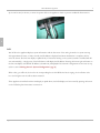
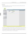
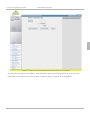
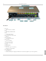
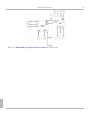
PIKA WARP the Appliance
User Guide
Copyright (c) 2008. All rights reserved.
PIKA WARP the Appliance
Table of Contents
Copyright Information
1
Contacting PIKA Technologies
2
Introduction
3
Related Documents
4
Getting Started - Hardware Installation
5
Getting Started - System Configuration
9
Using the Graphical User Interface
9
Editing Configuration Files
14
Making a Call
17
Advanced Configuration
20
System Information
24
Software Upgrade
27
Hardware Information
30
Troubleshooting
35
Specifications
36
Index
5/9/2008 - 1.0.0.180
a
User Guide
Page iii
1
PIKA WARP the Appliance
1
1 Copyright Information
COPYRIGHTS
Copyright
2008 PIKA Technologies Inc.
TRADEMARKS
PIKA is a registered trademark of PIKA Technologies Inc. All other trademarks, product names and company names
and/or logos cited herein, if any, are the property of their respective holders.
DISCLAIMER
This document is provided to you for informational purposes only and is believed to be accurate as of the date of its
publication, and is subject to change without notice. PIKA Technologies Inc. assumes no responsibility for any errors or
omissions in this document and shall have no obligation to you as a result of having made this document available to
you or based upon the information it contains.
5/9/2008 - 1.0.0.180
User Guide
Page 1
PIKA WARP the Appliance
2
2 Contacting PIKA Technologies
2
Customer Care
PIKA Technologies provides free technical support to all customers. For support issues, phone or e-mail our
Customer Care department at the following:
Tel:
+1-613-591-1555
FAX:
+1-613-591-9295
Email:
[email protected]
International Headquarters
PIKA Technologies Inc.
535 Legget Drive, Suite 400
Ottawa, Ontario, Canada K2K 3B8
Tel:
+1-613-591-1555
FAX:
+1-613-591-9295
Email:
[email protected]
Internet
Visit our website at www.pikatechnologies.com for the latest news, product announcements, downloads, online
community, documentation updates, and contact information.
Page 2
User Guide
5/9/2008 - 1.0.0.180
3
PIKA WARP the Appliance
3 Introduction
PIKA WARP the Appliance for Asterisk is designed for low-cost Asterisk-based applications in the Small Office/Home
Office (SOHO) and Small/Medium Enterprises (SME) markets. It is compatible with VOIP phones as well as analog
sets.
3
The appliance is available with up to nine analog ports: a built-in FXS port and eight additional ports using four-port
FXS and FXO daughter boards in any combination that plug in to the base board. The Ethernet port provides support
for VOIP stations and trunks.
The appliance for Asterisk uses PIKA's HMP (Host Media Processing) software for analog support. The Asterisk
software and PIKA's Channel Driver for Asterisk provide analog and IP PBX support. The Asterisk GUI software can
be used from any standard web browser to configure the appliance for use with Asterisk.
Key Features
•
•
•
•
•
•
•
•
•
•
•
•
•
•
•
•
AMCC Power PC 440EP Embedded Processor
10/100BT Ethernet port
256 Megabytes of RAM
One USB 1.1 host port
One FXS port with every unit
Two module expansion bays
4-port FXS modules and 4-port FXO modules may be installed in any combination
An RJ-11 power failover transfer jack is available on each four-port module
Audio in, Audio out jacks for music-on-hold and paging functions
Externally removable SD flash memory card
40 character/image (2 x 20) reversible LCD backlit display with scroll button (API controlled)
Reset Button
External brick-format universal power supply
Surface standalone/stackable or wall mountable to accommodate any space requirements
Customizable look so you can promote your brand
Dynamic thermal management
Software Components
• PIKA's HMP software
• Asterisk and Asterisk GUI software
• PIKA's channel driver for Asterisk
5/9/2008 - 1.0.0.180
User Guide
Page 3
PIKA WARP the Appliance
3.1 Related Documents
• Utilities from PIKA
• Third-party utilities
• Software Development Suite for custom application development, refer to the PIKA Application Development
Suite (PADS) User Guide for more information.
3.1 Related Documents
3
The following documents are related to the PIKA WARP the Appliance User Guide. These documents are linked
together and constitute the complete set of documentation for PIKA WARP the Appliance. All documents are available
at http://www.pikatechnologies.com/appliancedownloads.
PIKA Application Development Suite (PADS) User Manual: This guide describes the software development kit to
develop software for the appliance.
PIKA WARP the Appliance Hardware Manual: This manual describes the base board and plug-in modules.
PIKA WARP the Appliance Release Notes - These notes describe the contents of the release, including known
product issues.
Page 4
User Guide
5/9/2008 - 1.0.0.180
4
PIKA WARP the Appliance
4 Getting Started - Hardware Installation
Unpacking
The following items should be included with the appliance. Please check your package contents to ensure that you have
received all of the items.
•
•
•
•
•
•
•
•
power supply
Ethernet cable
serial cable (for use during application development)
1 GB SD (Secure Digital) card, formatted for an ext2 file system
1 4-port FXO module, mounted in the appliance
1 4-port FXS module, mounted in the appliance
PIKA screwdriver
getting started instruction sheet
4
Network Connection
Connect the appliance to your network using the NIC port as shown below.
Power Connection
Connect the power cable as shown below to the rear AC socket on the appliance and plug the other end into your AC
electrical outlet. The appliance's auto-sensing power supply can be plugged into either 110V or 220V electrical service. A
5/9/2008 - 1.0.0.180
User Guide
Page 5
PIKA WARP the Appliance
4
zip tie can be used, as shown, to secure the power cable to the appliance chassis to prevent accidental disconnection.
4
LCD
The LCD on the appliance displays system information and the line status of the analog channels. At system start-up,
after approximately twenty to thirty seconds, the IP address is displayed and when initialization is complete, the line
states are shown. The line state display is updated only if Asterisk is running on the system (Asterisk is installed and will
start automatically). A single press of the LCD button will display the IP address. Pressing the button again will return to
the line state display. The default IP address (192.168.1.80) is displayed if the network configuration has not been set up
(refer to section Getting Started - System Configuration ( pg. 9)).
When a line goes offhook, the icon for the corresponding line is solid. While the line is ringing, the icon flashes. The
icon is solid again once the call has been answered.
If the appliance is installed such that the display is upside down, the LCD display can be reversed by pressing the button
on the LCD face plate three times in succession.
Page 6
User Guide
5/9/2008 - 1.0.0.180
4
PIKA WARP the Appliance
4
FXS/FXO Port Connections
The FXS (Foreign eXchange Subscriber) interface is the port that delivers battery current, ring voltage, and dial tone to
the phones. Phones are plugged into FXS ports. The "wall jack" where the lines from the telephone company enter the
local premises is also an FXS port.
The FXO (Foreign eXchange Office) interface is the port that provides on/off-hook indication (loop closure) to the
public telephone network. It is also the plug on a phone or fax machine. Since an FXO port is attached to a device, such
as a fax or phone, the device is often called the ‘FXO device’. FXO ports are connected to the (FXS) "wall jack" where
the lines from the telephone company enter into the local premises.
FXO and FXS are always paired,that is, they are similar to a male / female plug.
Note:
All cables to FXO and FXS ports must use wire thicker than 26 AWG
The appliance is shipped with one four-port FXO module to connect to the FXS ports provided by the telephone
company, one four-port FXS module and one built-in FXS port to connect to phone or fax devices. For easy
identification, the ports on the appliance are color coded: the FXS ports are green while the FXO ports are orange. The
opposite color port on each module is the power failure transfer port. Refer to Hardware Information ( pg. 30) for
more information.
5/9/2008 - 1.0.0.180
User Guide
Page 7
PIKA WARP the Appliance
4
Audio In/Out Ports
4
The appliance provides one line-in and one line-out port which deliver telephony audio quality. Line-in is used to
receive audio from an external source (for example, an MP3 player, a CD player or FM radio). The external audio is
typically used for music on hold. Line-out allows a live person or pre-recorded message to be played outside the system,
for example, to a paging system. Standard 3.5 mm audio jack cables should be used with the audio ports.
Page 8
User Guide
5/9/2008 - 1.0.0.180
5.1 Using the Graphical User Interface
PIKA WARP the Appliance
5 Getting Started - System Configuration
PIKA WARP the Appliance for Asterisk is shipped with the necessary software installed to function as an Asterisk
IP/Analog PBX.
The major software components on the system include:
•
•
•
•
•
•
Linux operating system with appliance-specific modifications, based on kernel version 2.6.24-rc6
PIKA HMP drivers version 2.4 to support the appliance hardware
Asterisk PBX software version 1.4.14
Web-based Asterisk GUI to configure Asterisk and upgrade the software on the appliance
PIKA Asterisk channel driver version 3.3 to support the appliance hardware with Asterisk
Software utilities, including SSH and NTP
5
The appliance is ready to use when the system finishes booting. After configuring your network settings, the system is
ready to make Asterisk calls. In order to access the appliance from your network, you will need to enter some additional
information. You will need an IP address that is valid on your local network, as well as information about your local
network configuration to complete this step. To perform these changes, you will need to connect to the appliance using
a network cable (included).
The following sections describe how to configure the appliance using both the Asterisk GUI and by editing
configuration files. More advanced configuration changes for both the appliance itself and Asterisk are described in
section Advanced Configuration ( pg. 20).
The following sections assume that the standard software packages listed above are installed on the appliance. To
customize the appliance software, refer to the PADS User Manual.
5.1 Using the Graphical User Interface
The Asterisk GUI is included as part of the standard software on the appliance and can be accessed from a standard
web browser (with the exception of Microsoft Internet Explorer version 7.0 and above). It provides the ability to
configure Asterisk, network information and to upgrade the software on the appliance. The appliance is factory preset
to static IP address 192.168.1.80. To access the GUI, enter the following URL in any web browser:
http://192.168.1.80:8088/asterisk/static/config/cfgbasic.html
5/9/2008 - 1.0.0.180
User Guide
Page 9
PIKA WARP the Appliance
5.1 Using the Graphical User Interface
Initial Login
The first screen (shown below) is the login screen. The default userid is 'admin' and the default password is 'admin'.
Enter the userid and password and click "Login".
5
The configuration tool homepage is shown below. The pages use a common layout style. The left-most panel provides
menu links to configure Asterisk and system options. The center panel is where information pertaining to the selected
menu item is displayed and entered. The right-most panel displays tool-tips which provide help information about a
given field when the mouse pointer is positioned over the field. The "Activate Changes" option restarts Asterisk which
may be necessary if you have made any changes to your Asterisk configuration.
Page 10
User Guide
5/9/2008 - 1.0.0.180
5.1 Using the Graphical User Interface
PIKA WARP the Appliance
5
To change the password for userid "admin", under the Options menu, select "Change Password" at the top of the
center panel as shown below. Note that this will not change the Linux root password on the appliance.
5/9/2008 - 1.0.0.180
User Guide
Page 11
PIKA WARP the Appliance
5.1 Using the Graphical User Interface
5
Network Configuration
Select the Networking menu from the left panel. You will be presented with the following screen.
Page 12
User Guide
5/9/2008 - 1.0.0.180
5.1 Using the Graphical User Interface
PIKA WARP the Appliance
5
SSH is enabled by default and cannot be enabled or disabled using the checkbox. Enter a value for Hostname if desired.
Select "LAN" from the choices at the top of the center panel. You will be presented with the following screen.
5/9/2008 - 1.0.0.180
User Guide
Page 13
PIKA WARP the Appliance
5.2 Editing Configuration Files
5
The values shown for the IP address, Netmask and Gateway are the preset factory defaults. DHCP is not used by
default. Enter the values that are appropriate for your network configuration. Changes do not take effect until after a
reboot. Return to the GUI homepage and click the "Reboot" button to reset the appliance.
Network Settings in the PADS User Manual describes more detailed information about the network information
settings. The additional information in this section is important when configuring the appliance for software
development.
5.2 Editing Configuration Files
Use an SSH client to open a session to IP address 192.168.1.80. The appliance ships with a "root" user account and the
corresponding password is "pikapika".
Changing the root Password
To change the root password enter the following at the Linux command prompt:
Page 14
User Guide
5/9/2008 - 1.0.0.180
5.2 Editing Configuration Files
PIKA WARP the Appliance
passwd root
Follow the prompts to enter and confirm the new password. Password information is preserved across reboots.
Network Configuration
The file /etc/networking.conf contains the information required to configure the appliance for use on your network.
The initial contents of this file (based on the preset factory defaults) are:
# Default Warp network configuration
##
# IP_LAN
# IP address to configure on the network interface
IP_LAN=192.168.1.80
##
# NETMASK_LAN
# Netmask to configure on the network interface (relative to IP_LAN)
NETMASK_LAN=255.255.255.0
5
##
# GATEWAY_LAN
# IP Address of the default route
GATEWAY_LAN=192.168.1.1
##
# SSH_ACCESS
# Enable/disable ssh (yes|no)
SSH_ACCESS=yes
##
##
# DHCP_LAN
# Use dhcp to configure networking
# IP_LAN must not be set for DHCP_LAN=yes to be honored
# yes|no
DHCP_LAN=no
##
# DNS_LAN
# IP address of the DNS server to use
#DNS_LAN=192.168.1.1
##
5/9/2008 - 1.0.0.180
User Guide
Page 15
PIKA WARP the Appliance
5.2 Editing Configuration Files
# HOSTNAME
# Name under which this host should be known
HOSTNAME=warp
You may add an optional entry (no default is present) to enter the domain for your LAN, such as "yourcompany.com".
DOMAIN_LAN=
Change the values as appropriate for your network configuration. Note that SSH is enabled in the default software on
the appliance and cannot be enabled or disabled by changing the value of "SSHACCESS".
When you have finished entering the necessary information, enter the command "reboot" and the Linux prompt on the
appliance to reset the appliance to enable your configuration changes.
Network Settings in the PADS User Manual describes more detailed information about the network information
5
settings. The additional information in this section is important when configuring the appliance for software
development.
Page 16
User Guide
5/9/2008 - 1.0.0.180
6
PIKA WARP the Appliance
6 Making a Call
Once you have completed your network configuration, you are ready to make calls using Asterisk. For your first call on
the appliance, it is recommended that you connect a standard phone set into the built-in green FXS port and dial 600.
This will connect you to the Asterisk echo test recording and will guide you through a set of audio prompts to for the
play and record functions in Asterisk.
The following table lists some default Asterisk extensions that you may find useful.
Extension Purpose/Destination
600
Asterisk echo test recording
1000
Asterisk demo congratulations recording
8500
Voice mail setup.
500
Attempts an IAX connection to a Digium server, this will only work if you have provisioned IAX trunks
in Asterisk.
1000
IVR (in addtion to the demo congratulation recording)
• 3
• 2
• #
• returns to the top level of the IVR menu (normally changes the language to French, French language files are not
installed by default on the appliance)
• plays a recording that describes Asterisk
• good bye
PIKA Extensions
To make calls using the appliance hardware, the following dial plan contexts and extensions have been appended to the
default extensions provided in the file /etc/asterisk/extensions.conf. Existing extensions in the default Asterisk dial
plan continue to work.
The following contexts have been defined:
Context
Usage
[fxo]
PIKA context to use with the appliance FXO ports
5/9/2008 - 1.0.0.180
User Guide
Page 17
6
PIKA WARP the Appliance
[fxs]
PIKA context to use with the appliance FXS port
[DID_trunk_1]
Default FXO context, used by the GUI
6
[numberplan-custom-1] Default context provisioned for the appliance, used by the GUI
6
Extension
Purpose/Destination
2222
Connects to the audio in port to listen to the audio sent from an external device such as an MP3 player.
2233
Connects the handset microphone to the audio out port on the appliance, used for paging.
2244
Begins playing pre-recorded prompts to the audio out port on the appliance. After dialing, if you hang
up, the prompts will continue to play.
2255
Stops the pre-recorded prompts started by dialing extension 2244.
4001 to
4005
These extensions call FXS lines 1 to 5, respectively. If the FXS module is not present, the call will be
routed to voice mail.
4006 to
4010
These extensions call the sample SIP Agents defined in sip.conf. If the SIP agent associated with the
extension is not registered, the call will be routed to voice mail.
4060
PIKA FAX receive test. Connect a FAX machine to one of the FXS ports, dial this extension and the
appliance will receive the FAX. A tiff file will be stored in /tmp/warpfax.
4061
PIKA FAX transmit test. Connect a FAX machine to one of the FXS ports, dial this extension and the
appliance will send a test FAX (the PIKA logo) to your FAX machine.
9<number> Calls out on an available FXO extension. If no FXO extensions are available, congestion will be received.
Note: Voice mail passwords for extensions 4001 through 4010 are the extension number.
The PIKA FAX application has been enabled for both FXO and FXS lines. If FAX tones are detected on any analog
line, a call is automatically placed to extension 4060 to receive the FAX. For more information about the PIKA FAX
application, please visit http://www.pikatechnologies.com/asterisk.
Port Numbering - Provisioning versus LCD
On the LCD, ports are numbered sequentially, one through nine, regardless of the module type inserted into the module
bay. When phones and trunks are provisioned in Asterisk configuration files, ports are numbered sequentially based on
the module type. FXS ports are always numbered one through five, where port one is always the built-in FXS port.
FXO ports are always numbered one through four. In the following diagram, the FXO module installed in the first bay,
which is closest to the built-in FXS port. The FXS module is in bay two. The numbers shown on the back view are the
Page 18
User Guide
5/9/2008 - 1.0.0.180
6
PIKA WARP the Appliance
port numbers to use when configuring Asterisk (e.g. fxs/1 in the dial plan). The bottom view of the LCD shows the
same module installation and the associated port numbering.
6
5/9/2008 - 1.0.0.180
User Guide
Page 19
PIKA WARP the Appliance
7
7 Advanced Configuration
To further customize your configuration, you will need to access the appliance either through SSH or a serial
connection. The appliance ships with a "root" user account and the corresponding password is "pikapika".
Configuring the PIKA Asterisk Channel Driver
The channel driver is a specialized piece of software to allow Asterisk to use the appliance hardware. It is included as
part of the standard software shipped with the appliance. The configuration file for the software is generated at startup
time, based on the type of hardware modules plugged into the base board. The software is ready for use upon initial
shipment.
You can customize the Asterisk features available for the analog ports by modifying the configuration file
/etc/asterisk/pika.conf. Documentation for the configuration file is located at
http://www.pikatechnologies.com/asterisk. Select "Downloads and Docs" from the left menu and select the
manpage link under "PIKA Analog Station/FXS".
7
NOTE: PIKA hardware is auto-detected and the file pika.conf is generated based on the current hardware
configuration. If the hardware configuration is changed (e.g. swapping, adding or removing modules),
pika.conf will be overwritten when the system is rebooted. If you have made any changes to pika.conf, create
a backup copy of the file before rebooting.
Sending Voice Mail Messages to the SD
When voice mail files are generated, by default, Asterisk is configured to store the files in /var/spool/asterisk. Files in
this directory are not preserved across system reboots. The use of the SD is recommended to permanently store these
files. To send the files to the SD card, make the following configuration changes. To use the SD, it must be inserted at
system startup time.
1. Edit the file /etc/asterisk/asterisk.conf and change the spool directory to the following:
astspooldir = /mnt/sd/asterisk/
Page 20
User Guide
5/9/2008 - 1.0.0.180
7
PIKA WARP the Appliance
2. Create the directory /mnt/sd/asterisk/voicemail/default by entering the following commands at the Linux prompt.
Note that to use the SD, it must be inserted at boot time.
mkdir /mnt/sd/asterisk
mkdir /mnt/sd/asterisk/voicemail
mkdir /mnt/sd/asterisk/voicemail/default
3. Connect to the Asterisk console and restart Asterisk by entering the following commands on the appliance.
asterisk -r
restart now
Alternatively, log in to the Asterisk GUI and use "Activate Changes" on the right side panel of the home page to restart
Asterisk.
Refer to Hardware Information ( pg. 30) for more information about using the SD card.
Configuring Asterisk on the Appliance for use Outside North America
Asterisk on the appliance is configured by default for North America. To configure the appliance for operation in other
countries, perform the following steps:
1. Stop Asterisk by entering the following commands at the Linux command prompt:
asterisk -r
stop now
7
2. At the appliance Linux prompt, enter the following command:
pikacf
• You will be presented with a series of questions to configure your hardware. Choose the appropriate country code
and defaults will be selected to configure your FXS and FXO ports. If your country code does not appear, press 'c'
when presented with the following prompt:
Enter two letter country code, for example 'US' for United States.
(Enter '?' to display the list of supported country codes or
'c' to customize individual parameters)
Country code: [US]
• You will be asked for information regarding your companding mode and caller id mode. Choose the appropriate
values for your country.
Compand mode, ulaw or alaw: (Enter '?' for help) [ulaw] alaw
5/9/2008 - 1.0.0.180
User Guide
Page 21
PIKA WARP the Appliance
7
Select one of the following caller id modes
1. FSK BELLCORE
2. FSK ETSI
3. FSK BT
4. FSK NTT
5. DTMF ETSI
6. DTMF DK
7. DTMF SE FI
8. None
Selection: (Enter '?' for help) [8]
NOTE: Any country for which there is a predefined configuration will have the correct line impedance value set.
Configuration for other countries (entered by selecting 'c' at the country code prompt) will use the North
American value. There is no configuration file entry to change the line impedance.
7
3. Change the indication tones for Asterisk in the file /etc/asterisk/indications.conf
• In the [general] section, if your country is in the list of the default countries below, modify the line "country=" as
appropriate.
• If your country is not in the list, please use the template shown in the file to create a section that defines the tones
for your country.
4. Restart Asterisk by entering the following at the Linux command prompt:
asterisk
Call Progress
Call progress uses inband tone patterns (such as ringing, busy or fast busy) received from remote devices to determine
why a call has been disconnected. Enabling call progress ensures that billing does not start until a two-way speech
connection has been established. Call progress is enabled by default for the analog ports on the appliance. Only North
American call progress tones have been defined and therefore, call progress may not work outside of North America.
Two options are available for this situation:
1. Disable call progress (recommended)
• In the file /etc/pika/pikagp.cfg, change all entries in the file that match "callpa=callpa_settings" to
";callpa=callpa_settings".
• In the file /etc/pika/pikagp_aoh.cfg, change all entries in the file matching ";answer=speech" or "answer=speech"
to "answer=none".
Page 22
User Guide
5/9/2008 - 1.0.0.180
7
PIKA WARP the Appliance
2. Modify the tone definitions in /etc/pika/inccpa.cfg to correspond to the values for your country. The comments in
the file and the following websites provide information about defining the tones.
• www.3amsystems.com/wireline/tone-search.htm
• www.itu.int/dms_pub/itu-t/oth/02/06/T02060000040002PDFE.pdf
7
5/9/2008 - 1.0.0.180
User Guide
Page 23
PIKA WARP the Appliance
8
8 System Information
System information about network interfaces and resource usage is available through the Asterisk GUI. Select the
System Info menu from the left panel. The screen below will be presented, providing information about the operating
system and Asterisk software.
8
To view information about the network interfaces, select "ifconfig" from the top of the center panel. Information for
both the Ethernet and local interfaces will be displayed. The IP address should match the setting under the
Networking/LAN menu.
Page 24
User Guide
5/9/2008 - 1.0.0.180
8
PIKA WARP the Appliance
To view system resource usage, select "Resources" from the top of the center panel. Disk usage indicates how much
persistent memory is in use by the various types of file system devices including the SD and USB drive, if present. The
size is specified in kilobytes.
Memory usage indicates how much of the 256 Megabytes available in RAM is in use. The size is specified in kilobytes.
5/9/2008 - 1.0.0.180
User Guide
Page 25
8
PIKA WARP the Appliance
8
8
Page 26
User Guide
5/9/2008 - 1.0.0.180
9
PIKA WARP the Appliance
9 Software Upgrade
To upgrade the software on the appliance, use the Asterisk GUI and select the "Update" menu from the left panel. The
following screen will be displayed.
9
Two types of software for the appliance can be upgraded: the Ramdisk (the main system software) and the kernel (the
operating system software). New software can be obtained from PIKA Technologies at
http://www.pikatechnologies.com/appliancedownloads or you can build new software images using the software
development kit. Refer to Building Software for the Appliance in the PADS User Manual.
The location of the software images can be either a URL or a TFTP (Tiny File Tranfer Protocol) server. For
information about setting up an TFTP server, refer to
5/9/2008 - 1.0.0.180
User Guide
Page 27
PIKA WARP the Appliance
9
Development System Setup and Configuration in the PADS User Manual.
To upgrade from a URL, specify the full URL path, including the file name. For example, http://<IP
Addr>/cuImage.warp (the kernel image name). To use a domain name, an IP address for a DNS server must be
configured in the networking configuration settings. Otherwise, you must use the IP address of the server.
To upgrade from a TFTP Server, enter the IP address of the server and the file name (case-sensitive) of the software
image, including the subdirectory relative to the root directory of the TFTP server. The root directory is the base
directory to which the TFTP server is allowed access.
Click "Go" to continue. A progress dialog box will be displayed.
WARNING:
• Do not disrupt the system during the upgrade process by rebooting or powering down the system.
• Ensure that the correct file for the image type is selected for the upgrade.
If the system is powered cycled or the wrong file type is used, the system will not function when it
attempts to restart and it will be necessary to connect to the system using a serial cable to recover. Refer
to the information below.
If the upgrade fails at any time during this stage, after the next reboot, the system will no longer function. Refer to
9
sections Development System Setup and Configuration and Installing and Running Software in the PADS User
Manual to set up your development computer to use alternative methods to upgrade the software. Do not reboot the
system until you have explored the possible upgrade methods listed in the PADS User Manual.
If the upgrade is successful, a dialog box will be displayed:
Page 28
User Guide
5/9/2008 - 1.0.0.180
9
PIKA WARP the Appliance
Click "Ok" to continue. You may then use the"Reboot" option on the GUI Home menu to reboot the system, or enter
the command "reboot" from the Linux prompt on the appliance if you are connected to the appliance using either SSH
or serial access.
9
5/9/2008 - 1.0.0.180
User Guide
Page 29
PIKA WARP the Appliance
10
10 Hardware Information
Hardware Reset
The reset button is located on the back of the appliance beside the SD slot. A pointed object, such as a pen, must be
used to press the button. To avoid possible data loss, it is recommended that a software reboot is attempted first and
only if this fails, resort to a hardware reset.
SD Card
The appliance includes a slot for a removable SD card. A 1 GB card is supplied with the kit. The following photos show
the insertion and removal of a card. A pointed object, such as pen, must be used to fully insert and release the card from
the slot. When fully inserted, the card is recessed slightly into the casing.
10
The SD is intended to store any run-time data that must survive across system resets, such as voice mail files, log files or
to transfer files to another computer. For use with Asterisk, the card must be formatted for an ext2 file system (most
cards are formatted as FAT by default). When the card is inserted into the system, the Linux operating system expects
to read the contents of an ext2 file system. The file system format on the SD card provided is ext2, however, there is
software is available on the appliance to format the card, if required.
Page 30
User Guide
5/9/2008 - 1.0.0.180
10
PIKA WARP the Appliance
If the SD card is inserted before the system is reset or powered up, it will be ready for use when the system completes
the startup sequence. If the card is removed while the system is running, any data on the card will be lost unless it is
manually removed from the file system. If the card is inserted while the system is running, it must be manually added to
the file system or no data will be stored. To use the SD with Asterisk, it must be available in the file system before
Asterisk is started, therefore, it is recommended that the card is always inserted before system reset or power-up. If the
card is removed while the system is running and Asterisk is configured to use it, Asterisk must be stopped before the
card can be removed from the file system.
Refer to the Utilities section in the PADS User Manual for instructions to format the card and to add/remove the card
from the file system.
SD cards with a capacity of up to 4 GB are compatible. The following SD cards are recommended for use with the
appliance:
•
•
•
•
•
SanDisk SDSDB - 2048 (2 GB)
SanDisk SDSDB - 4096 (4 GB)
HP L1876A (1 GB)
PNY SD M01G (1 GB)
Lexar (2 GB)
USB Port (1.1 Compliant)
The USB port can be used for logging, auto-flashing the appliance during production (refer to Advanced Options
Menu in the PADS User Guide for instructions to auto-flash the appliance) or as a general purpose external hard drive.
Note that the USB drive will not be automatically added to the Linux file system in the appliance, regardless of whether
it is inserted into a system at run-time or before system startup. Once you have inserted the USB drive, to add it to the
file system, enter the following command at the Linux prompt on the appliance:
mount /mnt/usb
Before removing the USB from a live system, you must unmount the USB key from the file system or data may be lost.
Enter the following command at the Linux prompt on the appliance before removing the USB device:
10
umount /mnt/usb
For use with Asterisk, the USB drive must be formatted for an ext2 file system. Refer to the Utilities section in the
PADS User Manual for instructions to format the USB drive for Asterisk.
Installing the FXO and FXS Modules
Ensure that the appliance is powered off. You must be grounded with an anti-static wrist strap (not provided). Using a
5/9/2008 - 1.0.0.180
User Guide
Page 31
PIKA WARP the Appliance
10
screwdriver, remove the screws on each of the side panels on the appliance. Remove the top cover.
Remove the grey panel on the back of the appliance as shown below. Use a flat object or thin slot screwdriver to lever
the panel at the left and right upper corners. By hand, push the panel from the back through the slot into the casing.
Rotate the panel up and down inside the casing to break the lateral tabs. Take care when rotating the panel that you do
not damage the casing at the top of the slot.
The black module bay connectors are highlighted in the following image. FXO or FXS modules can be inserted into
either bay. If only one module is present, it can be inserted into either bay. Align the module pins with the connector
and insert the module into the connector. The module should be secured to the base board by setting the module on
top of the posts provided (circled below) and the screws should be inserted through the gold holes on the the module.
10
Page 32
User Guide
5/9/2008 - 1.0.0.180
10
PIKA WARP the Appliance
Power Failure Transfer
On each FXS and FXO module, the opposite colored port is the power failure transfer port (green on each FXO
module and orange on each FXS module). If there is a power failure, the appliance can continue to draw power from
the telephone company. On the FXO module, if the line from the phone company is plugged into the first port beside
the power failure transfer port, a phone can be plugged into the power failure transfer port to make outgoing calls.
On the FXS module, a line from the telephone company can be plugged into the power failure transfer port. This allows
a phone plugged into the first port beside the power failure transfer port on the module to make outgoing calls.
Once the power returns, if the power failure port is still in use, the first port on the module cannot be used until the line
plugged into the power failure port is unplugged.
Thermal management
The appliance performs automatic temperature control and monitoring. Under normal ambient temperature levels, the
fan will not run. If the temperature reaches a minimum threshold of 50 degrees Celsius (122 degrees Fahrenheit), the
fan will start automatically at low speed. If the temperature continues to increase, the speed of the fan will increase
accordingly, eventually reaching full speed. If the fan is on and the temperature decreases to 47 degrees Celsius (116.6
degrees Fahrenheit) , the fan speed will begin to decrease and eventually shut off completely if the temperature remains
below 50 degrees Celsius (122 degrees Fahrenheit).
10
When the temperature reaches a maximum threshold of 65 degrees Celsius (149 degrees Fahrenheit) :
• the system will halt
• the LED will flash red
• the analog and Ethernet interfaces will not function
• the power failure transfer port(s) will still function
Logs generated to indicate fan activity can be found in the file /var/log/messages. The log messages in this directory are
cleared when the system is rebooted.
5/9/2008 - 1.0.0.180
User Guide
Page 33
PIKA WARP the Appliance
10
Wall Mounting
The appliance can be stacked or wall mounted. When wall mounted, the appliance rests on the back 2 feet, therefore it
is recommended that you do not remove the feet so that the unit remains stable. The appliance should be mounted with
the LCD at the top and not mounted sideways, otherwise, the unit will be unstable. The following photo shows the slots
used to hang the unit on the screws that are inserted into the wall. The screw heads must protrude 5/16" from the wall.
The wall mounting template can be found at: www.pikatechnologies.com/appliancedownloads.
10
Page 34
User Guide
5/9/2008 - 1.0.0.180
11
PIKA WARP the Appliance
11 Troubleshooting
Software Upgrade Using the GUI Fails
The following entries (present by default) must exist in /etc/asterisk/extensions.conf or none of the configuration
changes entered using the GUI will be stored. No error messages are generated to indicate that these entries are missing.
If this information has accidentally been deleted, edit /etc/asterisk/extensions.conf and add the information to the end
of the file.
[asterisk_guitools]
exten = executecommand,1,System(${command})
exten = executecommand,n,Hangup()
exten = record_vmenu,1,Answer
exten = record_vmenu,n,Playback(vm-intro)
exten = record_vmenu,n,Record(${var1})
exten = record_vmenu,n,Playback(vm-saved)
exten = record_vmenu,n,Playback(vm-goodbye)
exten = record_vmenu,n,Hangup
exten = play_file,1,Answer
exten = play_file,n,Playback(${var1})
exten = play_file,n,Hangup
hasbeensetup = Y
11
5/9/2008 - 1.0.0.180
User Guide
Page 35
PIKA WARP the Appliance
12
12 Specifications
Chassis Overview
Top View
Rear View
12
Page 36
User Guide
5/9/2008 - 1.0.0.180
12
PIKA WARP the Appliance
Base Board
• Processor:
• AMCC Power PC, 533 MHz
• Flash
• 4MB NOR, 256 MB NAND
• RAM
• 256 MB DDR SDRAM
• Rear-accessible removable storage:
• SD card
• Network Interface:
• 10/100BT Ethernet port
• USB 1.1 Ports:
• one rear accessible
• Audio Line In/Out Ports
• 3.4 KHz audio quality
• FXS port:
• 48 Volt ringing
• Form Factor:
• 8.780” W x 2.026” H x 6.585” D
• Stackable or wall mountable
• Power Requirements
• 12 Volts DC, 2 A
• NOTE: The LPS power supply provided must be used with the appliance, as per safety regulations.
5/9/2008 - 1.0.0.180
User Guide
12
Page 37
PIKA WARP the Appliance
12
Refer to the PIKA WARP the Appliance Hardware Manual for more details.
12
Page 38
User Guide
5/9/2008 - 1.0.0.180
13
PIKA WARP the Appliance
Index
T
A
Troubleshooting 35
Advanced Configuration 20
U
C
Using the Graphical User Interface 9
Contacting PIKA Technologies 2
Copyright Information 1
E
Editing Configuration Files 14
G
Getting Started - Hardware Installation 5
Getting Started - System Configuration 9
H
Hardware Information 30
I
Introduction 3
M
Making a Call 17
R
Related Documents 4
S
Software Upgrade 27
Specifications 36
System Information 24
5/9/2008 - 1.0.0.180
User Guide
Page a