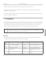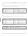
1
PIKA WARP the Appliance
Hardware Manual
Copyright (c) 2010. All rights reserved.
PIKA WARP the Appliance
Table of Contents
1 Copyright Information
1
2 Contacting PIKA Technologies
2
3 Introduction
3
Related Documents
3
4 Overview
4
5 Regulatory Information
5
Compliance
7
6 Appliance Description
10
Base Board
10
Appliance Enclosure Mechanical Description
12
Jumper Settings
13
Connector Pinouts
14
Appliance Modules
15
FXO Module
15
FXS Module
16
BRI Module
17
7 Technical Specifications
18
Base Board
18
FXO Module
20
2/26/2010 - 2.1.0.403
Hardware Manual
Page iii
PIKA WARP the Appliance
FXS Module
21
BRI Module
23
8 Glossary
24
Index
Page iv
a
Hardware Manual
2/26/2010 - 2.1.0.403
1
PIKA WARP the Appliance
1 Copyright Information
1
COPYRIGHTS
Copyright
2010 PIKA Technologies Inc.
TRADEMARKS
PIKA is a registered trademark of PIKA Technologies Inc. All other trademarks, product names and company names
and/or logos cited herein, if any, are the property of their respective holders.
DISCLAIMER
This document is provided to you for informational purposes only and is believed to be accurate as of the date of its
publication, and is subject to change without notice. PIKA Technologies Inc. assumes no responsibility for any errors or
omissions in this document and shall have no obligation to you as a result of having made this document available to
you or based upon the information it contains.
2/26/2010 - 2.1.0.403
Hardware Manual
Page 1
PIKA WARP the Appliance
2
2 Contacting PIKA Technologies
Customer Care
2
For support issues, phone or e-mail our Customer Care department at the following:
Tel:
+1-613-591-1555
FAX:
+1-613-591-9295
Email:
[email protected]
International Headquarters
PIKA Technologies Inc.
535 Legget Drive, Suite 400
Ottawa, Ontario, Canada K2K 3B8
Tel:
+1-613-591-1555
FAX:
+1-613-591-9295
Email:
[email protected]
Internet
Visit our website at www.pikatechnologies.com for the latest news, product announcements, downloads, online
community, documentation updates, and contact information.
Page 2
Hardware Manual
2/26/2010 - 2.1.0.403
3.1 Related Documents
PIKA WARP the Appliance
3 Introduction
This document describes the hardware components of PIKA WARP the Appliance.
Guide Organization:
Overview ( pg. 4) - Describes the high level features of the appliance
Regulatory Information ( pg. 5) - Describes regulatory bodies and conformance to the applicable regulations
Appliance Description ( pg. 10) - Describes the functionality of the base board and available plug-in modules
Technical Specifications ( pg. 18) - Detailed technical information about the base board and plug-in modules
3
Glossary ( pg. 24) - Description of terms and acronyms
3.1 Related Documents
The following documents are related to the PIKA WARP the Appliance Hardware Manual. These documents are linked
together and constitute the complete set of documentation for the PIKA WARP the Appliance product. All documents
are available at http://www.pikatechnologies.com/appliancedownloads.
PIKA Application Development Suite (PADS) User Manual: This guide describes the software development kit to
develop software for PIKA WARP the Appliance.
PIKA WARP the Appliance User Guide: This guide describes installation and configuration of the appliance.
PIKA WARP the Appliance Release Notes - These notes describe the contents of the release, including known
product issues.
2/26/2010 - 2.1.0.403
Hardware Manual
Page 3
PIKA WARP the Appliance
4
4 Overview
The appliance is a flexible, self-contained platform for voice processing systems. The Appliance accommodates VoIP
traffic, and up to two line interface modules. Three types of modules are currently available: a 4 FXS/Station (plus PFT)
module, a 4 FXO/Trunk (plus Power Failure Transfer port) and a BRI module. All signal processing functions such as
conferencing, audio playback/record and echo cancellation are performed on the internal PPC440EP processor. The
analog line interface hardware is software programmable to interface with North American or European
telecommunications standards.
Interfaces
The PIKA Appliance provides the following analog and digital interfaces:
4
• 10/100BT network port
• One FXS/Station port
• Up to a total of two modules of the following types:
• 4 port FXS/Station (plus power failure transfer (PFT) port ) module
• 4 port FXO/Trunk (plus power failure transfer port ) module
• 2 port BRI module
• Audio In/Out ports
• USB 1.1 port
• Removable SD flash card interface
MAC Address and Serial Number
Each appliance has a MAC address and a serial number, found on the bottom label. The MAC address is hexadecimal,
in the format AB:CD:EF:12:34:56. The serial number format is PIK-123-45678.
Page 4
Hardware Manual
2/26/2010 - 2.1.0.403
5
PIKA WARP the Appliance
5 Regulatory Information
Regulatory Warnings
Industry Canada (IC)
Equipment Attachment Limitations
NOTICE: The Industry Canada label identifies certified equipment. This certification means that the equipment meets
certain telecommunications network protective and operational safety requirements. The department does not guarantee
that the equipment will operate to the user’s satisfaction.
Before installing this equipment, users should ensure that it is permissible to connect to the facilities of the local
telecommunications company. The equipment must also be installed using an acceptable connection method. The
customer should be aware that compliance with the above conditions might not prevent degradation of service in some
situations.
Repairs to certified equipment should be made by an authorized Canadian maintenance facility designated by the
supplier. Any repairs or alterations made by the user to this equipment, or equipment malfunctions, may give the
telecommunications company cause to request the user to disconnect the equipment.
5
For their own protection, users should ensure that the electrical ground connections of the power utility, telephone lines
and internal metallic water pipe system, if present, are connected together. This precaution may be particularly
important in rural areas.
CAUTION: Users should not attempt to make such connections themselves, but should contact the appropriate
electrical inspection authority, or electrician, as appropriate.
Federal Communications Commission (FCC)
This section contains information applicable to system integrators, to ensure that the use of the appliance complies with
FCC part 68.
1. The appliance must be mounted into the final assembly so it is isolated from exposure to any hazardous voltages with
the assembly. Adequate separation and restraint of cables and cords must be provided.
2/26/2010 - 2.1.0.403
Hardware Manual
Page 5
PIKA WARP the Appliance
5
2. The TIP/RING leads from the appliance must be wired to the telephone lines in wiring that carries no other circuitry
than that specifically allowed in FCC Part 68 rules. Any board traces carrying TIP/RING leads should have sufficient
spacing to avoid surge breakdown.
3. The appliance must be connected to the supplied LPS compliant power adapter to be safety compliant.
Consumer Information
The following information applies to consumers, and should be included by system integrators in their customer
documentation.
1. The appliance complies with Part 15 and Part 68 of the FCC rules. It is verified to comply with the limits for Class
“A” Digital Device pursuant to Part 15 of FCC rules. These limits are designed to provide reasonable protection
against harmful interference when the equipment is operated in a commercial, industrial or business environment.
This equipment generates, uses and can radiate radio frequency energy and, if not installed and used in accordance
with the instruction manual, may cause harmful interference in which case the user will be required to correct the
interference at his own expense. The label on the bottom of the PIKA Applianc contains the FCC registration
number and REN for this equipment. If requested, provide this information to your telephone company.
2. The REN is useful to determine the number of devices you may connect to your telephone line and still have all of
those devices ring when your number is called. In most, but not all areas, the sum of the RENs of all devices should
not exceed five (5.0). To be certain of the number of devices you may connect to your line, as determined by the
REN, you should contact your local telephone company to determine the maximum REN for your calling area.
5
3. While the appliance conforms to the applicable telecommunications network regulations, if a malfunction occurs, it
may cause harm to the telephone network. In this case, the telephone company may discontinue your service
temporarily.
4. Your telephone company may make changes in its facilities, equipment, operations, or procedures that could affect
the proper operation of your equipment.
5. If you experience trouble with the appliance, please contact PIKA Technologies for repair/warranty information (see
Contacting PIKA Technologies ( pg. 2)). The telephone company may ask you to disconnect this equipment from
the network until the problem has been corrected or you are sure the equipment in not malfunctioning.
6. The appliance may not be used on coin service provided by the telephone company. Connection to a party line is
subject to state tariffs. Contact your state public utility company or corporation commission for information.
European Telecommunications Standards Institute (ETSI)
TBR 21: 1998, Clause 4.8.1 stipulates restrictions on equipment with an automatic seizing and dialing function.
TBR 21: 1998, Clause 4.8.3 stipulates restrictions on equipment with automatic repeated call attempt ability.
Page 6
Hardware Manual
2/26/2010 - 2.1.0.403
5.1 Compliance
PIKA WARP the Appliance
TBR 21: 1998, Clause 4.7.3 stipulates limitations of sending levels for transmission signals.
The appliance is dependant on a third party application for the above clauses and therefore compliance with these
requirements cannot be guaranteed.
PIKA Technologies hereby declares this product is not intended for connection to the public telephone network unless
all aspects of compliance are addressed.
5.1 Compliance
The appliance is certified compliant for use in the United States, Canada, and European Union countries. The following
tables list approval information for EMC/EMI, Telecom, and Safety standards. Testing for all regulatory disciplines was
performed at the Nemko product certification and compliance test facility. The tables list each country or region, its
approval standard, registered approval numbers (if any), and a short description of the approval standard.
Note:
The term self-declared indicates that the board was tested by a third-party test facility, but does not require
an official approval number by a country or region’s approval standard authority. For the TBR21 Telecom
specification, testing was performed by an in-house test facility.
5
EMC/EMI
EMC/EMI standards govern the amount of electromagnetic interference and immunity of electrical devices. The
following table lists the EMC/EMI approval information for the appliance.
Country /
Region
Approval Standard
Approval Number Approval Description
United
States
FCC 47 CFR Part 15, Subpart B
Self-declared
Rules for EMC/EMI emissions
Canada
ICES-003 Issue 4 Feb 2004
Self-declared
Rules for EMC/EMI emissions
Europe
EN55022: 1998
Self-declared
Limits and measurement of EM
Emissions
Europe
EN55024: 1998 + ammend. A1, A2
Self-declared
Limits and measurement of EM
Immunity
2/26/2010 - 2.1.0.403
Hardware Manual
Page 7
PIKA WARP the Appliance
5.1 Compliance
Telecom
Telecom standards govern the necessary electrical signals and protocols of telecommunications devices. The following
table lists the Telecom approval information for the Analog Trunk/FXO board.
Country /
Region
Approval Standard
Approval Number Approval Description
United
States
TIA-968-A (-1 to -5)
6PRIS01B9900910
Rules for registration of telephone
equipment
Canada
CS-03 Issue 9
1689A-9900910
Standard for terminal Equipment
connected to wireline facilities
Safety
Safety standards govern the human safety of all electrical devices. The following table lists the safety approval
information for the Analog Trunk/FXO board.
5
Country /
Region
Approval Standard
Approval Number Approval Description
United
States /
Canada
CSA C22.2 No. 950 NRTL/C
1115017
(LR105564-4)
Safety standard for IT and telecom
equipment
Europe
EN60950
Self-declared
Safety of IT and electrical business
equipment
The following table lists the approval information for the BRI module.
Country/Region Approval
Standard
Approval Number
Approval Description
Europe
Self-declared
Safety of IT and electrical business equipment
Page 8
EN60950
Hardware Manual
2/26/2010 - 2.1.0.403
5.1 Compliance
PIKA WARP the Appliance
NOTE: In order for the appliance to comply with safety regulations, a user-supplied power adapter must NOT be
substituted for the PIKA-provided adapter. Additionally, the unit must be positioned horizontally with the
product label at the bottom, or secured to a wall, with the interface connectors at the bottom.
RoHS
The appliance and modules are all 2002/95/RoHS 6 compliant.
5
2/26/2010 - 2.1.0.403
Hardware Manual
Page 9
PIKA WARP the Appliance
6.1 Base Board
6 Appliance Description
The following sections provide a detailed description of the Appliance's functionality, including the following
information:
•
•
•
•
•
Base Board ( pg. 10) – high-level overview of the base board circuitry
Appliance Enclosure Mechanical Description ( pg. 12) – physical dimensions of the appliance enclosure
Jumper settings ( pg. 13) – jumper setting for NOR Flash reprogramming using a JTAG tool
Connector pinouts ( pg. 14) – description of electrical connection on connectors
Appliance Modules ( pg. 15) – description of available daughter boards
6.1 Base Board
The following figure is a high-level functional diagram of the appliance.
6
The PPC440EP is a multi-bus processor with many peripheral options. Instructions and volatile data are transferred
across a dedicated DDR SDRAM bus. USB, ethernet and serial ports are directly pinned out of the processor. All other
peripheral functions, including communications with the modules are mediated through the FPGA.
Page 10
Hardware Manual
2/26/2010 - 2.1.0.403
6.1 Base Board
PIKA WARP the Appliance
The FPGA implements all TDM data transfer, synchronization, and auxiliary functions for the board.
The baseboard FXS port, audio ports and module ports share a common common 4.096 MHz, 64-slot stream. Each
line interface contains its own codec and other line circuitry. Digital audio is transmitted over the shared stream to and
from the codec. The digital audio is then converted into an analog signal and processed by the analog line circuitry,
which interfaces to the telephone network.
Appliance Reset Button
In the event that an application causes an unrecoverable error, a small pointed object (such as a pen) can be inserted
into the hole on the left hand side of the SD card slot. This will activate a momentary switch that performs a hardware
reset.
LCD and Display Button
A graphic LCD with software backlight control is provided with the appliance. Various software-controlled display
features are controlled by a "touchless" switch, which is found on the right-hand side of the LCD display.
Power/Health LED
A bi-colour LED located on the right-hand side of the LCD indicates that the appliance is powered and functioning.
When the appliance first powers on, the LED lights up red. As soon the boot sequence begins, it turns red-green. If
appliance boots successfully (the bootloader downloads the FPGA and completes the power on self test (POST)), the
LED turns green. Subsequent run-time errors, such as the unit overheating or undetectable hardware, may revert the
LED to red or red-green.
6
USB Port
The USB port on the appliance is a USB 1.1 compliant host port. It connects directly to the PPC440EP processor and is
protected by a reset-able fuse.
Secure Digital Card Slot
The SD card slot supports only cards that are fully SD compliant, bear the SD logo
and do not require SPI
mode for initialization. High capacity (HC) cards are supported.
2/26/2010 - 2.1.0.403
Hardware Manual
Page 11
PIKA WARP the Appliance
6.2 Appliance Enclosure Mechanical Description
Audio Ports
The appliance is outfitted with an audio in port for music on hold, and an audio out port for paging. The ports use the
standard 3.5 mm audio jacks found on many commercial devices, such as MP3 players. Although the audio paths are
mono, the audio in path sums a stereo source, and the audio out path plays out the audio on both left and right outputs.
6.2 Appliance Enclosure Mechanical Description
The following figure shows a diagram of the dimensions of the board: Three views are shown:
• Top view (looking down on the board).
• Side view (looking at the side with line interface modules).
• End view (looking straight at the end with the connector).
6
Note:
All measurements are imperial values.
The following diagram shows the exploded view of the appliance enclosure. The table below shows the legend for the
diagram.
Page 12
Hardware Manual
2/26/2010 - 2.1.0.403
6.3 Jumper Settings
PIKA WARP the Appliance
No. Part Number
Description
1
PIK-04-00004-PIKA-Enclosure-Bottom
Enclosure Bottom
2
PIK-04-00002-PIKA-Enclosure-Frame-Insert-Assembly
Appliance Enclosure Frame Insert Assembly
3
PIK-04-00000-PIKA-Enclosure-Top-Insert-Assembly
Appliance Enclosure Top Insert Assembly
4
PIK-04-00006-PIKA-Enclosure-Window
Enclosure Window
5
PIK-04-00005-PIKA-Enclosure-Component-Mount
Appliance Enclosure Component Mount
6
X925-Foot-Dome-U2
Spherical Rubber Good
6
Thermal Management
Due to varying operating conditions, an internal fan ensures that the appliance is kept within its internal operating
temperature range of 0 C (32 F) to 65 C (149 F). Once the internal temperature reaches 50 C (122 F), the fan will turn
on at low speed, then increase speed as needed to maintain the operating temperature range. Once the temperature goes
below 50 C (122 F), the fan will reduce its speed and will eventually turn off if this temperature can be maintained.
6.3 Jumper Settings
The appliance has one jumper, J13, which is used when programming the NOR flash with some JTAG tools, such as
2/26/2010 - 2.1.0.403
Hardware Manual
Page 13
PIKA WARP the Appliance
6.4 Connector Pinouts
Macraigor. Under normal circumstances, this method of programming the NOR flash is not required.
6.4 Connector Pinouts
RJ-11 Telecom Ports
The appliance provides connectivity to each of the analog line interfaces through RJ-21 connectors. The primary
tip-ring pair is used (refer to Appliance Modules ( pg. 15)).
The appliance provides connectivity to the BRI interfaces through RJ-45 connectors. A straight-through cable is
required. Refer to BRI Module ( pg. 17) for more details.
RJ-45 Ethernet 10/100BT Port
The Ethernet port uses the standard TX and RX twisted pairs, as per TIA/EIA-568-B. The ethernet port supports
auto-MDI/MDIX capabilities and will work with either a straight-through or crossover cable.
The following figure shows the connector pin-out.
6
RS-232 Port
A serial port is provided via shrouded connector J7 on the baseboard. It is set up as 115,200 baud, 8 data bits, no parity,
1 stop bit and no flow control.
The following figure shows the connector pin-out:
Page 14
Hardware Manual
2/26/2010 - 2.1.0.403
6.5 Appliance Modules
PIKA WARP the Appliance
FXO Module
6.5 Appliance Modules
The following sections describe the plug-in modules available for the appliance. For information about module
installation and removal, refer to section Hardware Installation in the PIKA Warp the Appliance User Manual for
more information.
NOTE: Screws must be used to secure the modules to the base board at all times to provide proper contact for frame
grounding.
6
6.5.1 FXO Module
The Analog Trunk/FXO board provides connectivity to analog central office loop start trunk line analog interfaces.
Typically, a phone is connected to a loop start line from the telephone company and is, by default, in an on-hook state.
When the phone goes off-hook, the phone completes the line circuit and current flows through the line. The telephone
company provides an audible dial tone to the phone and accepts dual-tone multi-frequency (DTMF) digits from the
caller.
The FXO module is equipped with four FXO ports and a power fail transfer port. If a power failure occurs, the power
2/26/2010 - 2.1.0.403
Hardware Manual
Page 15
BRI Module
PIKA WARP the Appliance
6.5 Appliance Modules
fail transfer (PFT) port is directly switched to FXO port 1 (adjacent to the PFT port). If power is restored and the PFT
port is in use, port 1 is not disconnected from the PFT port until the phone is hung up on the PFT port.
The loop start analog interface provides the following features:
•
•
•
•
•
•
•
•
•
Ringing Detection
Loop Disconnect Detection
Loop Reversal Detection
Loop Voltage and Current Monitoring
Detects when tip/ring voltage crosses a set voltage when on-hook or off-hook (called DC triggering)
Can accommodate private branch exchange (PBX) with –24 V or –48 V battery voltage
Voltage detection threshold is software programmable
Surge protected
Onhook audio reception with or without battery feed
6.5.2 FXS Module
The Analog Station/FXS module provides connectivity to standard analog phones. Typically, a phone is connected to a
station interface and is, by default, in an on-hook state. When the phone goes off-hook, the phone completes the line
circuit and current flows through the line.
The FXS module is equipped with four FXS ports and a power fail transfer port. If a power failure occurs, the power
fail port is directly switched to FXS port 1 (adjacent to the PFT port). If power is restored and port 1 is in use, the PFT
port is not disconnected from port 0 until the phone is hung up on port 1.
The analog station interface provides the following features:
6
•
•
•
•
•
•
•
•
•
•
•
Ringing Generation and Ringing Trip
Loop Closure Detection
Loop Disconnect
Loop Reversal
Loop Voltage and Current Monitoring
On-hook and Off-hook Transmission
Hook-flash Detection
DTMF Signaling
Programmable Impedance
Programmable Audio Gain
On-board Power Generation
Page 16
Hardware Manual
2/26/2010 - 2.1.0.403
6.5 Appliance Modules
PIKA WARP the Appliance
BRI Module
6.5.3 BRI Module
The BRI board provides connectivity to various devices that support BRI interfaces. Each module has two usable ports,
each providing a single span 2B+D interface for a total of 4 channels per module. RJ-45 dust jacks are inserted into the
unused ports.
The BRI interface provides the following features:
•
•
•
•
•
•
2 S/T Interfaces (2B+D per interface)
TE/NT mode support (software selectable on a per port basis)
100 ohm termination support (software selectable on a per port basis)
Point to Point and Point to Multipoint Support (software selecteable on a per port basis)
4 x RJ45 Connectors ( 2 unused )
Power consumption .096 watts
Connector Pinouts
6
2/26/2010 - 2.1.0.403
Hardware Manual
Page 17
PIKA WARP the Appliance
7.1 Base Board
7 Technical Specifications
This section describes the technical specifications for the main base board, the FXS, FXO, and BRI telephony modules.
7.1 Base Board
Base Board
Processor
AMCC Power PC 440EP Embedded Processor
Flash
Internal flash 4 MB NOR memory (uboot) plus 256 MB NAND (OS + apps)
RAM
256 MB DDR SDRAM
Removable storage
External removable SD flash memory
Network
10/100BT Ethernet port
USB
One USB 1.1 host port (v1.1)
Telecom FXS port
48V
Reset Button
Recessed hard reset button
Serial Interface
Onboard RS232 connector (internal)
Audio In/Out Ports
7
Input Impedance
15 K Ohm
Input Hardware Gain
+3 dB
Output Impedance
100 Ohm
Output Hardware Gain
-3 dB
Maximum Signal (dBm0)
3.14 dBm0
Maximum Signal (V)
0.762 Vrms
Physical Properties
Dimensions (Metric)
223 mm W x 52 mm H x 168 mm D
Dimensions (Imperial)
8.780” W x 2.026” H x 6.585” D
Page 18
Hardware Manual
2/26/2010 - 2.1.0.403
7.1 Base Board
Note:
PIKA WARP the Appliance
All dimensions are approximate.
Power Requirements
Power consumption from
12V adapter
24 W max
Power consumption from
LS lines
North America 1.4 W/line
European Union 2.0 W/line
Environment Requirements
Ambient Temperature
0 °C to +45 °C (32 to 113 °F)
Storage Temperature
-20 °C to +85 °C (-4 to 118 °F)
Humidity, non-condensing
5 % to 95 %
The unit can only be positioned horizontally with the product label at the bottom, or secured to a wall, with the
interface connectors at the bottom. Setting the unit on its side will impede proper ventilation.
WARNING: Proper system cooling must be ensured to maintain system stability and reliability. All fan and
louvre openings on the back and side of the appliance must be kept unobstructed and the
ambient temperature must be between 0 and 45 degrees Celsius (32 and 113 degrees
Fahrenheit) non-condensing.
Life Expectancy
The flash technology used in the appliance is an important factor in the longevity of the product. How many erase/write
cycles the devices undergo determines how many years the devices are usable. For NAND technology, the device allows
at least 100,000 program/erase cycles for each sector. However, the part can be used well beyond these numbers by
using a file system that uses a wear-levelling algorithm, preventing the repeated use of the same sectors if other free
sectors are available. First and foremost, the longevity of the flash will vary according to the flash programming
7
frequency of the application.
Mean Time Between Failure (MTBF)
2/26/2010 - 2.1.0.403
Hardware Manual
Page 19
PIKA WARP the Appliance
7.2 FXO Module
Base board with no modules 30.6 years
Base board with two
modules (FXO/FXS)
19.1 years
Power supply
20.44 years
7.2 FXO Module
Loop Start (FXO) Telephony Module Loop Start (FXO) Analog Module
AC Impedance (in audio band)
Off-Hook
600 ohms
On-Hook Metallic (Tip to Ring)
>300 k ohms
Return Loss
>26.8 dB
DC Current
Loop Current Range
13 – 110 mA
DC Resistance
Longitudinal (tip to ground, ring to ground)
>9.8 M ohms
On-Hook Metallic (Tip to Ring)
>6.5 M ohms
Off-Hook Metallic (Tip to Ring)
310 ohms @ 20 mA
117 ohms @ 100 mA
Ringing
Ring Detection
14 Vrms @16 Hz
14 Vrms @20 Hz
7
12 Vrms @68 Hz
Ringer Impedance (20 Hz)
> 26 M ohms
Ringer Equivalence Number (REN)
1
Gain Tolerance (Linearity)
Page 20
Hardware Manual
2/26/2010 - 2.1.0.403
7.3 FXS Module
PIKA WARP the Appliance
On-hook In (2 to 4 wire) NA
0.0 to 0.8 dB (300 to 3400 Hz)
Off-hook In (2 to 4 wire) NA
-1.5 to -0.4 dB (300 to 3400 Hz)
Off-hook Out (4 to 2 wire)
-4.8 to -0.7 dB (300 to 3400 Hz)
Gain Range
Fixed - On-hook H/W Gain In (2 to 4 wire)
-1.6 dB
Fixed - Off-hook H/W Gain In (2 to 4 wire)
-0.75 dB
Fixed - Off-hook H/W Gain Out (4 to 2 wire) +0.24 dB
On-hook Signal overload level @0 dB gain In
(2 to 4 wire)
+4.77 dBm
Off-hook Signal overload level @0 dB gain In +3.92 dBm
(2 to 4 wire)
Miscellaneous
Trans-hybrid loss (THL)
>27 dB (300-3400)
On-hook Common Mode Gain
-52.9 dBm0 avg.
Signal to Noise Ratio (15 dBm, 1 kHz
reference)
> 38 dB
On-Hook Inter Hybrid (Interface) Crosstalk
No measurable crosstalk
Off-Hook Inter Hybrid (Interface) Crosstalk
No measurable crosstalk
Idle Channel Noise
6 dBrnc
Transverse Balance
> 57 dB
Supervision
Ring Detection, Loop Disconnect, Reversal Detection, Loop Voltage,
Loop Current
Signaling
Off Hook,Flash, DTMF, Pulse Dial
Onhook Audio Detect
Caller ID, DTMF, Audio Logging
7
7.3 FXS Module
Analog Station (FXS) Telephony Module
AC Impedance (in audio band)
2/26/2010 - 2.1.0.403
Hardware Manual
Page 21
PIKA WARP the Appliance
Off-hook
600 ohms or TBR21 complex impedance
Return Loss
>30 dB
7.3 FXS Module
DC Current
Constant Loop Current
20 mA
Ringing
Ringing Amplitude
Vrms
Ringing Frequency
20 Hz
DC Bias
0V
Supported Ringer Equivalence Number
(REN)
1
Gain Tolerance (Linearity)
On-hook Out (4 to 2 wire)
+/- 0.5 dB (300 to 3000 Hz)
Off-hook In (2 to 4 wire) NA
+/- 0.5 dB (300 to 3000 Hz)
Off-hook Out (4 to 2 wire)
+/- 0.5 dB (300 to 3000 Hz)
Gain Range
Fixed - On-hook H/W Gain Out (4 to 2 wire) +1.2 dB
Fixed - Off-hook H/W Gain In (2 to 4 wire)
-3.9 dB
Fixed - Off-hook H/W Gain Out (4 to 2 wire) -3.7 dB
On-hook Signal Overload Level
+3.2 dBm
(Due to fixed H/W gain, max digital level is
+2 dBm0 with 0 dB of digital gain. If
maximum PCM transmission level of +3.2
dBm0 is required, digital gain should be set to
-1.2 dB.)
7
Off-hook Signal Overload Level
+7.1 dBm
Miscellaneous
Trans-hybrid loss (THL)
>30 dB (300 to 3400 Hz)
Signal-to-Noise + Distortion Ratio (signal
power from +3.14 to –30 dBm0)
> 35.5 dB
Page 22
Hardware Manual
2/26/2010 - 2.1.0.403
7.4 BRI Module
PIKA WARP the Appliance
On-hook Inter-Hybrid (Interface) Crosstalk
> -85 dB
Off-hook Inter-Hybrid (Interface) Crosstalk
-92 dB
Idle Channel Noise
12 dBrnc
7.4 BRI Module
BRI Telephony Module
Power Consumption
Maximum power consumption
.96 Watts
Telephony Interface
Interfaces
2 S/T Interfaces (2B+D per interface)
TE/NT mode support
software selectable on a per port basis
Point to Point and Point to Multi-point
Support
software selectable on a per port basis
Physical Connector
4 x RJ45 ( 2 unused )
Impedance
100 ohm (software selectable on a per port basis)
Miscellaneous
Mean Time Between Failure (MTBF)
208.33 years
7
2/26/2010 - 2.1.0.403
Hardware Manual
Page 23
PIKA WARP the Appliance
8
8 Glossary
Term
Definition
dB
Decibel - A logarithmic unit used to describe a ratio.
dBm
An abbreviation for the power ratio in decibel (dB) of the measured power referenced to one
milliwatt (mW).
dBm0
An abbreviation for the power in dBm measured at a zero transmission level point.
DDR
Double Data Rate - A type of signaling that transfers data on both the rising and falling edges of
the clock signal.
DTMF
Dual Tone Multi-Frequency - Telephone signaling used over the line in the voice-frequency band
LS
Loop Start - A method of starting (seizing) a telephone line or trunk by sending a supervisory signal
(going off-hook) to the Central Office. With loop start, you seize a line by bridging through a
resistance the tip and ring (both wires) of your telephone line.
CODEC
Coder/Decoder - Converts analog signals to digital signals.
CSA
Canadian Standards Association - An independent organization that establishes and tests safety
standards for electronic components and systems for the Canadian marketplace.
EMC
ElectroMagnetic Compatibility.- The sensitivity of a system to EMI.
EMI
ElectroMagnetic Interference - The interference in signal transmission and reception caused by
electrical and magnetic fields.
FCC
Federal Communications Commission - The government agency responsible for regulating
telecommunications in the United States.
FPGA
Field Programmable Gate Array - A semiconductor device containing programmable logic
components, called "logic blocks", and programmable interconnects.
FXO
Foreign Exchange Office - A telephone signaling interface that receives POTS, or "plain old
telephone service".
FXS
Foreign Exchange Station - A telephone interface which provides battery power, sends dialtone,
and generates ringing voltage.
IVR
Interactive Voice Response - A phone technology allowing a telephone caller to select options
from a voice menu and interact with the phone system.
JTAG
Joint Test Action Group - IEEE 1149.1 standard entitled Standard Test Access Port and
Boundary-Scan Architecture for test access ports used for testing printed circuit boards using
boundary scan and programming non-volatile storage.
8
Page 24
Hardware Manual
2/26/2010 - 2.1.0.403
8
PIKA WARP the Appliance
LCD
Liquid Crystal Display - A thin, flat display device made up of any number of color or
monochrome pixels arrayed in front of a light source or reflector.
LED
Light Emitting Diode - A semiconductor diode that emits incoherent narrow-spectrum light.
LPS
Limited Power Source - A type of power supply that must limit its current at a given voltage by
following a V-I curve provided by Safety regulatory bodies.
MDI/MDIX
Medium Dependent Interface - An Ethernet port connection typically used on the Network
Interface Card (NIC) or Integrated NIC port on a PC. The X stands for a crossover, where the
transmit and receive pairs are swapped.
MTBF
Mean Time Between Failure - The estimated average time before a failure occurs in a component.
NAND
A type of flash memory based on "not AND" logic gates.
NOR
A type of flash memory based on "not OR" logic gates.
NRTL
Nationally Recognized Testing Laboratory - The U.S. government body that determines if
products meet safety standards to provide the assurance these products are safe for use in the
workplace.
Ohm
The SI unit of electrical impedance or, in the direct current case, electrical resistance.
PCM
Pulse Code Modulation - A digital representation of an analog signal used in digital telephone
systems.
PFT
Power Failure Transfer - In the event of a power failure or a low-voltage battery condition at a
subscriber location, a type of port that supplies power to pre-designated subscriber equipment via
the central office trunk.
POST
Power On Self Test - Pre-boot sequence that identifies and verifies memory, interfaces and devices
for booting.
RAM
Random Access Memory - A form of integrated circuits that allow the stored data to be accessed
in any order.
REN
Ringer Equivalency Number - A number that denotes the loading a telephone ringer has on the
line.
RJ
Registered Jack - RJ are telephone and data jacks registered with the FCC.
SD
Secure Digital - A flash (non-volatile) memory card format for use in portable devices.
SDRAM
Synchronous Dynamic Random Access Memory - A type of computer memory that uses a
synchronous interface, meaning that it waits for a clock signal before responding to its control inputs.
SPI
Serial Peripheral Interface - A synchronous serial data link standard named by Motorola that
operates in full duplex mode. Devices communicate in master/slave mode where the master device
initiates the data frame.
THL
Trans-hybrid Loss - In a carrier telephone system, the transmission loss at a given frequency
measured across a hybrid circuit joined to a given two-wire termination and balancing network.
2/26/2010 - 2.1.0.403
Hardware Manual
8
Page 25
PIKA WARP the Appliance
USB
8
Universal Serial Bus - A standard for providing serial access to interface devices.
8
Page 26
Hardware Manual
2/26/2010 - 2.1.0.403
9
PIKA WARP the Appliance
Index
A
R
Regulatory Information 5
Related Documents 3
Appliance Description 10
Appliance Enclosure Mechanical Description 12
Appliance Modules 15
T
Technical Specifications 18
B
Base Board 10, 18
BRI Module 17, 23
C
Compliance 7
Connector Pinouts 14
Contacting PIKA Technologies 2
Copyright Information 1
F
FXO Module 15, 20
FXS Module 16, 21
G
Glossary 24
I
Introduction 3
J
Jumper Settings 13
O
Overview 4
2/26/2010 - 2.1.0.403
Hardware Manual
Page a