1
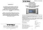
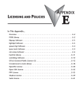
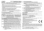
USER MANUAL
G.703 / FastEthernet Interface Converter
TAHOE 284
FREEDOM OF COMMUNICATION
TABLE OF CONTENTS
1. Introduction ........................................................................ 1
2. Interfaces ........................................................................... 2
3. Configuration and management ...................................... 4
3.1. Configuration using the LCD and keyboard ..................................
4
3.2. Configuration using the serial console ........................................
8
4. Technical data ................................................................... 9
5. Declaration of Conformity ................................................ 10
i
Tahoe® 284 (manageable G.703 / FastEthernet converter)
User Manual
http://www.tahoe-group.com/
Firmware version 1.0
©2004 Tahoe®. All rights reserved.
Other trademarks of other companies are used only for explanation and to
the owner's benefit, without intent to infringe.
Tahoe® assumes no responsibility for any errors or omissions that may appear in
this document. Tahoe® makes no commitment to update the information
contained here, and may make changes at any time without notice.
ii
1
1.
Introduction
Tahoe® 284 converter allows connecting of two LANs through an
E1 line terminated with balanced G.703 interfaces.
Converters work as transparent bridges, that is both
interconnected networks appear as a single LAN, as if both were plugged
into the same Ethernet switch.
Converter automatically learns, which Ethernet addresses are
heard on one and which on the other side. As a result local traffic is not
sent through the WAN link - converter discovers packets destined for the
other LAN and only those are directed to the G.703 interface.
The G.703 interface may work in both framed and unframed
mode. In the first case only selected timeslots may be used for data
transmission.
The converter may be managed using a built-in LCD and keyboard
or through a serial console.
1
2.
2
Interfaces
Following connectors are found on the rear of the converter:
Ethernet
serial
console
G.703
power
connector
power
switch
I
O
2.1.
2.1
Ethernet
The FastEthernet interface is used to connect the modem to the
Local Area Network. It may work at speeds of 10 Mbps (10Base-T) or 100
Mbps (100Base-T), in either full-duplex or half-duplex mode. The mode
of transmission may be selected automatically or manually.
Modem should be connected to a Ethernet switch or a hub using a
straight patch-cord or to a PC, a router or an uplink port in a switch using
a crossed-over one. After connecting a LED named “LAN Link” should be
lit.
2.2.
2.2
Serial console
The RS-232 serial console is used for modem management. It has
a DB9/M connector and works as a DTE, i.e. a null-modem cable should
be used to connect it to a PC. Three lines (bolded) are sufficient. Terminal
settings are 9600 bps, 8 data bits, 1 stop bit, no parity, no handshaking.
Pin
1
2
3
4
5
6
7
8
9
2
Name
DCD
RXD
TXD
DTR
GND
DSR
RTS
CTS
RI
Description
carrier detect, transmission readiness signaling
data received from the PC
data sent by the modem to the PC
active, when the PC is switched on
signal ground
active, when the modem is switched on
used by the PC to inform that is has data to send
used by the modem to permit data transmission
ring indicator (signal used in telephone modems)
2.3
2.3.
G.703
The G.703 interface is equipped with a 8-pin RJ-45 connector.
Although the G.703 standard does not specify the pinout, one used in
Tahoe devices is most widely used and a straight patch-cord may be used
to connect a converter to an external device. Anyway the pinout should
be carefully checked before connecting.
Pin
1
2
3
4
5
6
7
8
Signal
Rx+
RxTx+
Tx-
The RX+ pin of the converter should be connected to the TX+ pin
of the other device, the RX- pin to the TX- pin, TX+ to RX+ and TX- to RX-
3
3.
Configuration and management
3
The converter may be managed in two different ways - either
using a built-in LCD and keyboard or through a serial console.
The use of LCD and keyboard is the easiest way to configure the
converter - there’s no need to connect it to another device. On the other
hand the serial console may be used for remote management, when
connected for example to a port server or a remotely accessible PC.
3.1.
Configuration using the LCD and keyboard
The four-button keyboard and LCD can be found on the front
panel of the converter. After switching the power on following
information will be displayed:
Tahoe 284
2048 kb/s
UC
25’C
The device type, transmission speed. G.703 link status and inside
temperature are shown. The throughput may be set to 2048 kbps in
unframed mode and selected from 64-1984 kbps range in framed mode.
The G.703 link status is described using two letters in the upper
right corner of the LCD. In case of unframed mode letters “UC” may
appear. Letter “U” signals the unframed mode and “C” means that the
carrier signal was detected.
In the case of unframed mode letters “SC” may appear there.
Letter “S” means that the converter is synchronized to the E1 stream.
Letter “C” again signals, that the carrier was detected. If only “C” is
displayed, then the G.703 signal is present, but the converter is unable to
synchronize to it. Perhaps the signal detected is an unframed signal.
On the right side of the LCD four buttons are available: “up”,
“down”, “Escape” and “Enter”. By pressing “up” and “down” you can
browse the menu and select one of the options:
¡
¡
¡
¡
¡
¡
¡
4
throughput setting
timeslots selection
G.703 line coding and receiver sensitivity selection
G.703 receiver sensitivity selection
Ethernet port mode selection (autonegotiation or manual)
enabling and disabling 802.3xflow control, CRC4 and loopbacks
language selection
3.1
¡ saving settings to EEPROM
¡ converter reboot
The “Escape” key may be pressed anytime to return to the main
screen. Pressing “Enter” selects the option displayed.
3.1.1
3.1.1.
Throughput setting
Throughput:
2048 kb/s
After pressing Enter the throughput of the G.703 port may be set
using up/down buttons. It may be selected from a 64-2048 kbps range
with 64 kbps step.
Setting the throughput to 2048 kbps enables the unframed
mode. Lower values enable the framed mode, where only selected
timeslots are used for the transmission. The first timeslot (DS0) is used
for synchronization and following ones are used depending on the
throughput set - e.g. when it is set to 64 kbps the first (synchronization)
and second (data) timeslots are used. When set to 512 kbps - first
(synchronization) and second to ninth (data) are used.
3.1.2
3.1.2.
Timeslots selection
Timeslots
If a specific timeslot combination is necessary, it may be
selected using this option. After pressing “Enter” two lines of symbols
would appear - each symbol describes one timeslot:
S
g
§
3.1.3
3.1.3.
- timeslot used for synchronization in framed mode
- timeslot used for data transmission
- free timeslot
CRC4 checksum
CRC4:
on
After pressing “Enter” the CRC4 transmission and checking may
be either enabled or disabled.
5
3.1.4.
G.703 coding
3.1.4
G.703 line code:
HDB3
The G.703 port may use one of two available codings - HDB3
(used in most cases) and AMI.
3.1.5.
G.703 receiver sensitivity and range
3.1.5
G.703 port range
2000m
The G.703 port’s receiver sensitivity (thus port range) may be
changed - either -12dB (50m) or -43 dB (2000m)
3.1.6.
Ethernet port settings
3.1.6
Ethernet port:
Auto
By default the Ethernet port automatically selects the working
parameters - the throughput and full or half duplex mode. Anyway
these parameters may be set manually after selecting this option.
3.1.7.
MAC table entry expire time
3.1.7
MAC aging:
30s
The converter automatically learns which MAC (hardware)
addresses are heard on each side of the link. After a selected time (30s
or 300s) entries are removed from the table.
3.1.8.
802.3x flow control
802.3x Flow Ctrl
on
The flow control is user to prevent overloading a network
consisting of sections working with different speeds. When a certain
6
3.1.8
part of a network is unable to accept incoming traffic, the converter
may signal the condition to the remaining stations. These stations will
slow down the transmission rate preventing the loss of packets and the
need for numerous retransmissions.
3.1.9
3.1.9.
Test loopbacks
Test loop:
disabled
The test loopback are useful to diagnose the network problems.
Two kinds of loopback are available:
¡ towards Ethernet - packets received from the Ethernet port are
sent back to it
¡ towards G.703 port - packets received from the G.703 port are
sent back to it
3.1.10
3.1.10. Language selection
Language:
English
After pressing “Enter” the language used on the LCD and the
serial console may be changed.
3.1.11
3.1.11. Saving settings to EEPROM
Write config
to EEPROM
Every change to the configuration will be lost after reboot or
power off unless the settings are written to the EEPROM. After reaching
this option just press Enter to save them.
3.1.12
3.1.12. Converter reboot
Reboot device
(press Enter)
After pressing Enter the converter is rebooted. If some settings
were not saved to the EEPROM, they will be lost.
7
3.2.
Configuration using the serial console
After connecting the converter to a PC, running a VT-100 terminal
emulation software and switching the converter on a menu will appear:
main menu
G.703 port status
Ethernet port status
time elapsed
since power on
firmware version
and compilation date
Up and down arrows may be used to navigate through the menu.
Either Enter or right arrow should be pressed to select an option. To
confirm a changed parameter press Enter. To cancel a parameter change
press left arrow.
All options are identical to the LCD options described in 3.1. The
only addition is the “Refresh screen” function. When a working converter
is connected to the PC’s serial port the screen contents may be
incomplete - selecting this option or pressing Ctrl+L will refresh the
screen.
8
3.2
4
4.
Technical data
¡ processor:
ARM
¡ memory:
8MB SDRAM
¡ G.703 interface:
framed according to G.704 or unframed
balanced, 120W, RJ-45 connector
throughput:
64-1984 kbps or 2048 kbps
line coding:
AMI, HDB3
signaling:
FAS, CCS, CRC4
receiver sensitivity:
-12 dB / -43 dB
range:
50m / 2000 m
¡ WAN protocol:
HDLC
¡ Ethernet interface:
10/100Base-T, RJ-45 connector
¡ serial console:
RS-232, DB9/M connector
¡ dimensions:
200 mm (width) x 45 mm (height) x 130 mm (length)
¡ power supply:
15 V, 400 mA
external power supply included
¡ environmental conditions:
storage:
operation:
temperature
humidity
temperature
humidity
-20°C to 65°C
5 to 95%
0°C to 50°C
0 to 85%
9
5.
5
Declaration of Conformity
TAHOE
Piotr Kaczmarzyk
ul. Uniwersytecka 1
50-951 Wroclaw, Poland
We declare that the product Tahoe 284 complies with the
regulations of the following European Directives:
¡ 73/23/EEC
¡ 89/336/EEC
¡ 99/5/EEC
low voltage safety requirements
EMC requirements
radio & telecommunication
equipment requirements
terminal
The compliance of Tahoe 284 with the requirements of the above
mentioned directives is ensured by complete application of the following
harmonized European Standards:
¡
¡
¡
¡
EN 60950:2000
EN 55022:1998
EN 61000-6-1:2002
EN 61000-6-3:2002
Signed:
Position:
Piotr Kaczmarzyk
Director
Signature:
Date:
Place:
2 Feb 2004
Wroclaw, Poland
©2004 Tahoe®. All rights reserved.
Other trademarks of other companies are used only for explanation and to
the owner's benefit, without intent to infringe.
Tahoe® assumes no responsibility for any errors or omissions that may appear in
this document. Tahoe® makes no commitment to update the information
10
TAHOE®
Uniwersytecka 1
50951 Wroc³aw, Poland
phone +48 50 100 7362
fax +48 71 344 2642
http://www.tahoe-group.com/