1
USER MANUAL
G.shdsl+ modem with built-in router
TAHOE 681 / 682
FREEDOM OF COMMUNICATION
TABLE OF CONTENTS
1. Introduction ........................................................................ 1
2. Interfaces ........................................................................... 3
3. Modem configuration using built-in keyboard and LCD. 5
4. Configuration using telnet or serial console .................... 10
4.1. Telnet connection ............................................................. 10
4.2. Serial console ................................................................. 10
4.3. Commands ...................................................................... 11
5. Technical data .................................................................... 29
6. Declaration of Conformity ................................................. 30
i
Tahoe® 681/682 (G.shdsl+ / Ethernet 10/100Base-T modem)
User Manual
http://www.tahoe-group.com/
Firmware version 1.2.6
©2004 Tahoe®. All rights reserved.
Other trademarks of other companies are used only for explanation and to
the owner's benefit, without intent to infringe.
Tahoe® assumes no responsibility for any errors or omissions that may appear in
this document. Tahoe® makes no commitment to update the information
contained here, and may make changes at any time without notice.
ii
1
1.
Introduction
Thank you for purchasing the Tahoe 681/682 modem. We did our
best to ensure highest reliability and performance of our products.
Devoting many years of research and development we are proud to
provide a superior quality device unfolding new possibilities for the use of
the copper lines.
Tahoe® 680 series modems are G.shdsl+ modems allowing data
transmission with speeds up to 4864 kbps on 2-wire line or up to 9728
kbps on 4-wire line. Thanks to powerful TCPAM-32 modulation
throughputs are much higher than using HDSL technique and reach is
nearly twice that of VDSL. Adding low cost of deployment, Tahoe
modems become an interesting alternative even for fiber optic
connections.
The modem exists in two versions:
¡ Tahoe® 681 -
up to 4864 kbps on 2-wire line
¡ Tahoe® 682 -
up to 9728 kbps on 4-wire line, traffic is
automatically divided between two lines, fall back to 2-wire mode
is done automatically in case o line failure
The modem has a built-in TCP/IP router and an Ethernet
10/100Base-T interface allowing connection directly to a LAN. Router
software supports IP, ARP, TCP, UDP and ICMP protocols. It is
manageable using telnet, SNMP, serial console or built-in LCD and
keyboard. Traffic statistics are available through WWW. Modem status
messages can be sent to a central server using syslog protocol.
One network interface may support more than one IP subnetwork
thanks to interface aliases (eth0:0, eth0:1, etc.) and VLAN interfaces
(eth0.1, eth0.2, etc.). Modem may also work as a bridge - in this mode
both interconnected networks create one whole on the hardware level
(e.g. computers with Microsoft® Windows™ operating system will see
each other in the network neighborhood).
A built-in DHCP/BOOTP server allows assigning of IP addresses,
network mask, router addresses and other parameters to the network
stations. DHCP/BOOTP Relay Agent listens for DHCP and BOOTP
requests and forwards them to a central server.
Modem supports Network Address Translation, i.e. makes it
possible for a whole network to access Internet using only one real IP
address. Additional firewall improves the network security by blocking
1
unwanted traffic basing on IP addresses, TCP or UDP ports and protocols
appearing in the received packets.
The system firmware is stored in the Flash memory - it is possible
to update it using the TFTP protocol. The configuration is stored in the
EEPROM memory.
2
2
2.
Interfaces
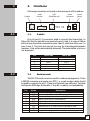
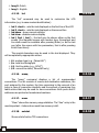
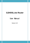
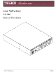
Following connectors are found on the rear panel of the modem:
LAN
(FastEthernet)
serial
console
G.shdsl
power
connector
power
switch
I
O
2.1
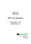
2.1.
G.shdsl
It is a 6-pin RJ-11 connector used to connect the leased line. In
Tahoe 681 the line should be connected to pins 3 and 4. In case of Tahoe
682 one line should be connected to pins 2 and 3, while the other one - to
pins 4 and 5. The first and second line may be interchanged between
modems - that will be automatically detected. The polarization of a line is
not important.
Pin
1
2
3
4
5
6
2.2
2.2.
Tahoe 681
line 1
line 1
-
Tahoe 682
line 1
line 1
line 2
line 2
-
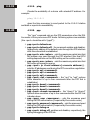
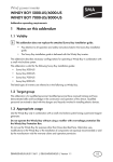
Serial console
The RS-232 serial console is used for modem management. It has
a DB9/M connector and works as a DTE, i.e. a null-modem cable should
be used to connect it to a PC. Three lines (bolded) are sufficient. Terminal
settings are 9600 bps, 8 data bits, 1 stop bit, no parity, no handshaking.
Pin
1
2
3
4
5
6
7
8
9
Name
DCD
RXD
TXD
DTR
GND
DSR
RTS
CTS
RI
Description
carrier detect, transmission readiness signaling
data received from the PC
data sent by the modem to the PC
active, when the PC is switched on
signal ground
active, when the modem is switched on
used by the PC to inform that is has data to send
used by the modem to permit data transmission
ring indicator (signal used in telephone modems)
3
After connecting the console to the PC and running a terminal
software, user has the same access to the modem functions, as through
a telnet connection (see chapter 4).
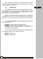
2.3.
FastEthernet
The FastEthernet interface is used to connect the modem to the
Local Area Network. It may work at speeds of 10 Mbps (10Base-T) or 100
Mbps (100Base-T), in either full-duplex or half-duplex mode. The mode
of transmission is selected automatically.
Modem should be connected to a Ethernet switch or a hub using a
straight patch-cord or to a PC, a router or an uplink port in a switch using
a crossed-over one. After connecting a LED named “LAN Link” should be
lit.
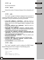
In the Tahoe® 681/682 modems the FastEthernet interface has
following status LEDs:
¡ LAN Link - lit, when modem is connected to a LAN
¡ LAN Act - LAN activity, blinks when data is sent or received
¡ 10/100M - LAN connection throughput - lit, when 100 Mbps
connection speed is negotiated
On the right two WAN status LEDs are present, blinking when data
is, respectively, received from or sent to the DSL line:
¡ WAN Rx- WAN Receive
¡ WAN Tx - WAN Transmit
4
2.3
3
3.
Modem configuration using built-in
keyboard and LCD
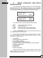
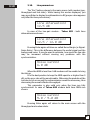
The easiest way to configure a modem is to use the four-button
keyboard and the LCD. After switching the power on, an information
about the modem type, the line throughput and state will be displayed.
The messages are different for Tahoe 681 and Tahoe 682 modems:
Tahoe 681
4864 kb/s
BOOT
Tahoe 682
9728 kb/s
BOOT
BOOT
Four-letter code on the right describes the DSL line state:
¡
¡
¡
¡
BOOT
IDLE
DOWN
SYNC
- booting of the G.shdsl transceiver
- transceiver inactive
- transceiver active, line not synchronized
- line synchronized, data may be transmitted
In case of Tahoe 682 modem, the top code describes the first
line, while the bottom - the second one.
On the right of the display there is a keyboard with “up”, “down”,
“Escape” and “Enter” keys. By pressing up/down buttons you may
browse the configuration menu:
¡
¡
¡
¡
¡
¡
¡
¡
¡
speed setting
modem type setting (Master/Slave)
line modulation selection
storing settings in the EEPROM memory
setting the IP address and network mask on the eth0 interface
selection of the language
connection reset
modem reset
bridge mode toggling
Each pressing of the “Escape” button causes the return to the
primary display with modem type and state. Pressing of the “Enter”
button selects given menu option.
5
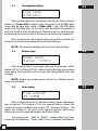
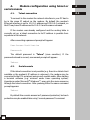
3.1.
Throughput setting
3.1
Line rate:
9728 kb/s
After pressing Enter the throughput may be set using up/down
buttons. In Tahoe 681 modem it may be chosen from 64-4864 kbps
range with 64 kbps step, while in Tahoe 682 - from 128-9728 kbps
range with 128 kbps step. In the latter case the actual throughput of
each line is half of the throughput set. Different rates for each line may
be set using the serial console or the telnet connection (see chapter 4).
After choosing the right speed and pressing Enter modem will
reset the connection and renegotiate it with new settings.
NOTE: The same throughput must be set on both modems.
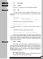
3.2.
Modem type
3.2
Modem type:
Master / HTU-C
After pressing Enter the modem type may be selected - either
Master (HTU-C) or Slave (HTU-R). After selecting the type and pressing
Enter again the connection will be reset and renegotiated with new
settings.
NOTE: Always one modem has to be set as a Master and the
other one as a Slave.
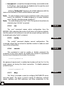
3.3.
Line coding
Line coding:
32-TCPAM
After pressing Enter the G.shdsl line coding (signal modulation)
may be chosen. The number (32 in the example above) means the
number of values encoded in one symbol (32 - 5 bits per symbol). The
higher this number is, the lower is the signal frequency, which gives
better immunity for signal attenuation and higher reach.
The second part - PAM or TCPAM - means either the Pulse
Amplitude Modulation or Trellis Coded Pulse Amplitude Modulation.
6
3.3
The latter is more efficient.
It is recommended to use the 32-TCPAM modulation, which
provides the best results. The remaining line codings are available to
provide compatibility with others’ manufacturers equipment. Moreover
32-TCPAM allows throughputs from 256 kbps to 4864 kbps per line,
while 16-TCPAM - from 64 kbps to 2304 kbps.
The “Auto” setting forces use of 32-TCPAM for speeds higher
than or equal to 256 kbps per line and 16-TCPAM for lower rates.
3.4
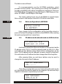
3.4.
Write configuration to EEPROM
Write config
to EEPROM
Every change to the configuration will be lost after reboot or
power off unless the settings are written to the EEPROM. After reaching
this option just press Enter to save them.
3.5
3.5.
IP address and network mask on eth0 interface
IP address and
netmask on eth0
As a factory default the Ethernet interface of the modem has the
IP address set to 10.0.0.1 and the network mask to 255.0.0.0. After
connecting to this address using telnet further configuration can be
done. The IP address may be changed, however, using the keyboard.
It’s useful when the IP address has been changed and then forgotten.
After pressing Enter, up and down buttons may be used to
change the first octet of the IP address:
Set IP address:
10._._._
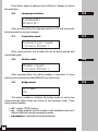
Then after pressing Enter second, third and fourth octet may be
set. Afterwards the network mask may be changed. Up and down keys
lengthen or shorten it, respectively, by one bit:
Set netmask:
255.0.0.0
7
Press Enter again to approve new settings or Escape to cancel
the operation.
3.6.
Language selection
3.6
Language:
English
After pressing Enter the language used on LCD and during the
telnet connection may be changed.
3.7.
Connection reset
3.7
Connection reset
(press Enter)
After pressing Enter the G.shdsl link will be disconnected and
negotiated again.
3.8.
Modem reset
3.8
Modem reset
(press Enter)
After pressing Enter the whole modem is rebooted. If some
settings were not saved to the EEPROM, they will be lost.
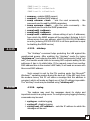
3.9.
Bridge mode
Bridge:
on
This option enables or disables the bridge mode, in which two
interconnected LANs create one whole in the hardware layer. Three
settings are available:
¡ off - regular TCP/IP routing
¡ on - bridge enabled, but the modem is still available under its IP
address and thus may be managed remotely
¡ transparent - completely transparent bridge
8
3.9
3.10
3.10.
Line parameters
The “Esc” button returns to the main screen (with modem type,
throughput and link state). While having this screen displayed, you
may press Enter to display line attenuation in dB (proper value appears
only after the line synchronizes):
Line attenuation:
12.5 dB
In case of the two-pair modem - Tahoe 682 - both lines
attenuations are shown:
Line attenuation:
12.5 / 12.0 dB
Pressing Enter again will show so-called Noise Margin (or SignalNoise Ratio). This is the difference between the useful signal and the
background noise. It may be used to estimate, how much the line rate
may be increased without causing any problems with the
synchronization.
Noise margin:
6.0 dB
When the NMR is less than 0 dB modems will be unable to bring
the link up.
It is the best practice to keep the NMR equal to or higher than 5
dB, so the error rate will be unnoticeable. Otherwise the packets will be
lost due to bit errors and the retransmission would be necessary, thus
decreasing the overall effective throughput.
This parameter is also valid only when the lines are fully
synchronized. In case of Tahoe 682 modem both lines NMRs are
shown:
Noise margin:
5.0 / 5.0 dB
Pressing Enter again will return to the main screen with the
throughput and modem state.
9
4.
Modem configuration using telnet or
serial console
4.1.
Telnet connection
4
4.1
To connect to the modem the network interface in your PC has to
be in the same IP subnet as the modem. By default the modem’s
Ethernet interface is set to 10.0.0.1 address and 255.0.0.0 netmask, so
the PC may have IP address set to 10.0.0.2 and the same netmask.
If the modem was already configured and the routing table is
correctly set up, a telnet connection to its IP address is possible from
anywhere in the network.
After connecting a password prompt will appear:
User Access Verification
Password:
The default password is “Tahoe” (case sensitive). If the
password entered is correct, a command prompt will appear:
Tahoe>
4.2.
Serial console
If the telnet connection is not possible (e.g. there’s no telnet client
available or the modem’s IP address is unknown), the modem may be
connected to the PC’s serial port using a null-modem cable. After starting
a terminal software (e.g. minicom under Linux operating system,
Hyperterm under Microsoft® Windows™) user gets the same access as
through the telnet connection. After pressing Enter the same command
prompt appears:
Tahoe>
By default the console access isn’t password protected, but such
protection may be enabled later using “console password” command.
10
4.2
4.3
4.3.1
4.3.
Commands
4.3.1.
?, help
Entering “?” or “help” shows a list of available commands.
4.3.2
4.3.2.
arp
The “arp” command is used to configure the ARP table. The “arp”
alone shows the list of connections between IP and hardware (MAC)
addresses:
Tahoe> arp
IP address
10.0.0.2
Hardware address
00:50:04:0D:70:31
dynamic
ARP table entries may be deleted using “arp del”:
Tahoe> arp del 10.0.0.2
(the IP address to be deleted should be typed instead of
“10.0.0.2” ).
A static ARP entry may be added using “arp add”:
Tahoe> arp add 10.0.0.3 00:50:13:E9:5C:01
The dynamic hardware address resolution may be disabled using
the “ifconfig” command. If it is disabled, only those stations may connect
to the modem, whose IP and MAC addresses are entered into the ARP
table using the “arp add” command. This way an unauthorized network
access may be prohibited.
4.3.3
4.3.3.
bridge
The “bridge” command enables or disables the bridge mode, in
which two interconnected LANs create one whole in the hardware layer.
The stations in both LANs behave like if they were connected to one
Ethernet switch, e.g. PCs working under Microsoft® Windows™
operating system will see each other in the network neighborhood.
Three settings are available:
¡ off - regular TCP/IP routing
¡ on - bridge enabled, but the modem is still available under its IP
address and thus may be managed remotely
11
¡ transparent - completely transparent bridge, inaccessible under
its IP address - this mode may be disabled only through the serial
console or the LCD and keyboard.
Entering “bridge list” displays a list of MAC addresses with the
name of the interface on which certain address was heard.
Note: To make bridging work properly interfaces used in the process
have to be indicated. To enable bridging on a certain interface
enter “ifconfig <interface name> bridge on”.
Note: To enable bridging the Cisco® HDLC link protocol should also be
selected using “dsl hdlc” command
4.3.4.
con
4.3.4
The „con” command erases whole configuration from the
EEPROM. After rebooting the modem it will return to its factory defaults.
Until the reboot it will continue to run with its current settings, which can
be saved again using “write” command.
4.3.5.
config
4.3.5
The „config” command displays current configuration. The
command output may be entered on another modem to make an exact
copy of the configuration.
4.3.6.
console
4.3.6
This command is used to enable or disable password the
protection of the serial console. By default the console is unprotected
and user has full access to the modem. By entering:
console passwd on
the password requirement is enabled and modem will ask for it in the
same manner as during the telnet connection. To disable password
protection type:
console passwd off
4.3.7.
dhcp
The “dhcp” command is used to configure DHCP/BOOTP server
and relay agent. The server is used to assign IP addresses, network
masks, gateway and DNS addresses and other parameters to the
12
4.3.7
network stations. It is easy to reconfigure a network that uses a DHCP
server - it is enough to change server settings and every station will
automatically retrieve new configuration.
The BOOTP protocol is an earlier and simpler version of DHCP. Its
common use is booting of diskless workstations. A workstation uses
BOOTP to get its IP address and other network parameters together with
TFTP server address, from which the operating system may be
downloaded.
The DHCP protocol may deliver more working parameters
including domain name, DNS address, print server, syslog server, XWindow fontserver, MTU and TTL settings, and many others.
DHCP/BOOTP Relay Agent transfers DHCP and BOOTP requests
and replies between separate networks. The DHCP and BOOTP protocols
work only within one physical subnet. The station using such protocols
doesn’t know its IP address yet, so its packets cannot be routed to other
networks. Relay Agent listens for such requests and forwards them to a
DHCP server, which may be placed anywhere in the network.
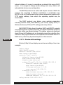
4.3.7.1
4.3.7.1. Review of the settings
Entering “dhcp” alone displays current server settings. Here is an
example:
Tahoe> dhcp
DHCP/BOOTP server
default-lease-time 43200
max-lease-time 86400
network "lan" (eth0):
default-lease-time 43200
max-lease-time 86400
domain-name tahoe.pl
subnet "local": 10.0.0.0/255.255.255.0
default-lease-time 43200
max-lease-time 86400
filename vmlinuz.2.2.19
next-server 192.168.0.5
routers 10.0.0.1
domain-name-servers 192.168.0.4
domain-name tahoe.pl
address ranges: 10.0.0.3-10.0.0.15
relay server 192.168.0.5 67
13
4.3.7.2. Basic DHCP server configuration rules
4.3.7.2
Before starting using DHCP server please read following
guidelines:
¡ the configuration is organized in a hierarchical manner - the most
general group of settings is “network” - the physical network
connected to the modem. Any number of IP “subnets” may exist
within a network. Inside an IP subnet an IP address “range” may
be selected - these addresses will be dynamically assigned to the
network stations. A static connection between an IP address and a
hardware address may also be set. Each group (“network”,
“subnet”) has its own options. Creating a new group (e.g. a
“subnet” within a “network”) causes copying of the options from
the parent group (e.g. if the “lan” network has a “domain-name”
option, after adding a “local” subnet within “lan” the option will be
automatically copied - it may be modified or deleted later)
¡ on the beginning a “network” for each interface should be created
¡ in each of the “networks” an IP “subnet” should be created
according to IP subnets connected to that interface (modem may
not have the routing set up to each of them - it’s enough that they
are in the same physical network)
¡ now IP ranges and static IP entries may be added
4.3.7.3. dhcp [ on | off | relay ]
4.3.7.3
DHCP/BOOTP server may work in one of three modes:
¡ on - the server in enabled and answers to the requests
¡ off - the server is disabled
¡ relay - the server is disabled, but the relay agent is enabled and
listens for the requests to be forwarded to other DHCP server
4.3.7.4. dhcp add
The “dhcp add” commands add a network, subnet, IP range, etc.
Following variants are supported:
¡ dhcp add network <name>
Adds a new physical network connected to the modem’s interface.
There should be the same number of “networks” and interfaces. The
“network”-interface connection will be determined later while adding the
IP subnets.
14
4.3.7.4
dhcp add network lan
¡ dhcp
add subnet <name> <network> <address>
<netmask>
Adds a net IP subnet to a given network. For each IP subnet
connected to the LAN or WAN interface an DHCP subnet should be added
(with the same IP addresses, as configured on each of the interfaces).
Moreover additional IP subnets may be added - those which are not set
up on any of the interfaces, but do exist in the same physical network or
behind a DHCP relay:
dhcp add subnet local lan 10.0.0.0 255.0.0.0
¡ dhcp add host <name> <MAC address> <IP address>
Adds a static connection between hardware (MAC) and IP
addresses. The IP address must belong to one of the configured subnets.
Only this IP address will be assigned to the given MAC address:
dhcp add host server 00:50:13:2e:15:ca 10.0.0.5
¡ dhcp add range <start address> <end address>
Adds an IP address range, from which addresses will be assigned
to the network stations. The address range must be contained inside one
of the subnets:
dhcp add range 10.0.0.5 10.0.0.37
¡ dhcp add option <option> <value>
Adds a global DHCP option sent to the requesting station.
Available options are:
- routers - network gateways (usually the gateways should be
separate for each subnet, so they shouldn’t be defined globally)
- domain-name - domain name
- domain-name-servers - DNS addresses
- filename - name of the file containing the operating system
- next-server - server from which the mentioned above file will
be downloaded using TFTP
dhcp add option domain-name tahoe-group.com
15
¡ dhcp add relay <address> [<port>]
Adds a DHCP server address to which the DHCP requests are
forwarded, when the Relay Agent mode is enabled. The <port>
parameter is optional - its default value is 67:
dhcp add relay 192.168.0.3
4.3.7.5. dhcp del
4.3.7.5
The command deletes a network, subnet, address range, etc.
¡ dhcp del network <name>
¡ dhcp del subnet <name>
¡ dhcp del host <name>
The commands above delete, respectively, a network, an IP
subnet or a host (a static IP-MAC connection) with given name.
¡ dhcp del relay <address>
Deletes a DHCP server address used in the Relay Agent mode.
¡ dhcp del range <start address> <end address>
Deletes an IP address range assigned to the network stations.
¡ dhcp del option <name> <value>
Deletes a global option. Besides the option name, its value should
also be given, because some options may have more than one value
(e.g. domain name servers, routers, etc.).
4.3.7.6. dhcp rename
4.3.7.6
The command changes the name of a network, subnet or host:
¡ dhcp rename network <old name> <new name>
¡ dhcp rename subnet <old name> <new name>
¡ dhcp rename host <old name> <new name>
4.3.7.7. dhcp network/subnet/host
The command adds or deletes an option within a specified group network, subnet or host. It has two forms:
16
4.3.7.7
¡ dhcp network add <option name> <value>
¡ dhcp network del <option name> <value>
(instead of „network”, a „subnet” or „host” may be given; options
are described in 4.3.7.4), e.g. :
dhcp network add domain-name tahoe-group.com
Options are valid only for a given network, subnet or host.
Moreover two other parameters can be set:
¡ dhcp network default-lease-time <value>
Sets the time (in second), for which the IP address is assigned to
the station. After that time the station must inform the DHCP server that
it still uses that address. Otherwise the address will be considered as
unused. This timeout prevents blocking an IP address when a station is
switched off without releasing that address.
¡ dhcp network max-lease-time <value>
A station may request other lease time - the negotiated time may
not be higher than this setting.
4.3.7.8
4.3.7.8. dhcp default-lease-time <value>
dhcp max-lease-time <value>
These commands are similar to those described in the previous
paragraph, but their meaning is global.
4.3.8
4.3.8.
dsl
This is a group of commands used to configure the DSL link.
Following options are available:
¡ dsl { fr | ppp | hdlc } - selects the protocol used to send data
through the line - Frame Relay, synchronous PPP or Cisco® HDLC.
The Cisco® HDLC is recommended if the modem has to work in
the bridge mode.
¡ dsl speed <value> [<second line>] - sets the line
throughput.
In case of Tahoe 681 modem the value should be selected from
64-4864 kbps range with 64 kbps step.
In Tahoe 682 modems the throughput may be set in two ways either by giving the total rate from 128-9728 kbps range, or by
17
giving separate values selected from 64-4864 kbps range for each
of the lines. The latter possibility is useful if the lines differ in their
quality.
New throughput will be set after entering “dsl reset” command.
¡ dsl type { master | slave } - sets the modem type - master or
slave. New mode is set after entering “dsl reset” command.
Always one modem should be set as a master, while the other one
as a slave.
¡ dsl mod { auto | tcpam32 | tcpam16 | tcpam8 | tcpam 4
| pam16 | pam8 | pam4 | pam2 } - selects line modulation.
The TCPAM32 modulation is recommended, as it is the most
efficient - the rest is available to provide compatibility with other
manufacturers’ devices. Moreover TCPAM32 allows throughputs
from 256 kbps to 4864 kbps per line, while TCPAM16 - from 64
kbps to 2304 kbps. The “auto” setting forces use of TCPAM32 for
speeds higher than or equal to 256 kbps per line and TCPAM16 for
lower rates.
¡ dsl reset - resets the DSL connection - the synchronization is
performed from the beginning
Entering “dsl” alone displays current settings.
4.3.9.
exit, quit
4.3.9
The command closes the configuration session and disconects
from the modem.
4.3.10.
fr
A group of commands used to configure the Frame Relay protocol
parameters. Following options are available:
¡ fr { ansi | q933a | cisco } - selects the LMI signaling: ANSI
T1.617 Annex D, ITU Q.933 Annex A or Cisco® LMI
¡ fr t391 <value> - sets the T391 parameter, i.e. the number of
failed retries during the communication through the LMI, after
which the connection is considered as unusable
¡ fr n391 <value> - sets the N391 parameter, i.e. the time
between subsequent LMI retries
¡ fr debug { on | off} - enables and disables sending the Frame
Relay debugging information through syslog
18
4.3.10
4.3.11
4.3.11.
http
The “http” command configures the built-in WWW server. It is
used to provide an easy way to read modem’s statistics. Server can be
enabled or disabled by entering, respectively:
http on or http off
Moreover the access to the server may be limited by typing:
http host <IP address>
Then the server is only reachable from the given IP address. To
remove the limitation a 0.0.0.0 address should be entered.
4.3.12
4.3.12.
ifconfig
The command allows configuring the network interfaces.
Following interfaces are available:
¡ eth0 - Ethernet interface
¡ eth0:0, eth0:1, etc. - eth0 interface aliases (one physical
interface may support several IP subnets)
¡ eth0.1, eth0.2, etc. - VLAN networks (LAN networks separated
from each other, although using the same cabling)
¡ eth0.1:0, eth0.1:1, etc. - VLAN interface aliases
¡ fr1, fr2, etc. - Frame Relay PVCs (the number after “fr” is the
DLCI of a given PVC)
¡ ppp0 - PPP interface used when the DSL link works in the PPP
mode
¡ wan0 - HDLC interface used when the DSL link works in the
Cisco® HDLC mode
This command has similar syntax as the Linux “ifconfig”:
ifconfig <interface name> [<IP address>] [netmask
<network mask>] [bcast <broadcast address>] [ static
| dynamic ] [bridge { on | off } ]
The “ifconfig” alone displays information about the active
interfaces. Entering “ifconfig <interface name>” shows information
about a certain interface. An information about interface’s IP address,
number of packets and bytes send and received, number of transmission
errors and other important data is displayed..
19
An IP address may be assigned to an interface, together with
subnet mask and broadcast address. A dynamic ARP may also be
enabled or disabled.
The “bridge” parameter allows to include or exclude certain
protocol from bridging, when the modem works in the bridge mode.
4.3.13.
ipchains
The command is used to control the firewall and the network
address translation (NAT, called also “masquerade” - that is giving a
network an access to the Internet using only one real IP address).
¡
¡
¡
¡
¡
ipchains add
ipchains insert
ipchains del
ipchains list
ipchains flush
- adds an entry at the end of the list
- adds an entry at the beginning of the list
- removes an entry
- displays current settings
- removes all entries from the list
After the “add”, “insert” or “del” option following parameters
should be given:
¡ -s <source subnet>/<netmask> [port range]
Defines the source addresses which this entry concerns. If this
parameter is omitted, then the entry concerns all source addresses.
¡ -d <destination subnet>/<netmask> [port range]
Defines the destination addresses which this entry concerns. If
this parameter is omitted, then the entry concerns all destination
addresses.
¡ -p <protocol> (optional)
Optionally the application of this rule may be limited to a certain
protocol.
¡ -y (optional)
The rule may be applied to the TCP SYN packets only (i.e. the
packets that initiate the TCP connection). It allows inhibiting the
incoming connections while the returning packets for the outgoing ones
will be passed.
20
4.3.13
¡ -m <IP address>
By default during the masquerade an outgoing interface’s IP
address is used. The option above allows forcing use of another address.
¡ accept / deny / masq - information, what to do with a packet,
that conforms to a given rule (accept / discard / masquerade)
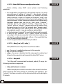
Note:
The modem always chooses the first matching rule from
the list. So if the more general rule comes first, and the more
specific is later, then the first one will be applied and the last one ignored. Thus the specific rule has to be inserted before the
general one, as in following example:
ipchains add -s 215.16.11.0/24 deny
ipchains insert -s 215.16.11.5 accept
Commands above inhibit the access for the whole 215.16.11.0/24
subnet except the 215.16.11.5 address.
Note:
The specific “accept” rule (concerning one IP address) has
to be inserted before the general one (concerning the whole
subnet), either using the “insert” command as in the example
above or by adding the specific rule first and then the general one.
Otherwise the router will always apply the first rule and will never
reach the second one, as the packet coming from 215.16.11.5 fits
both of them and if the general one is first, then it will be applied.
More examples:
ipchains add d 0.0.0.0/0 80-80 p tcp deny
Inhibits access to the port 80 on all external servers.
ipchains add s 192.168.0.0/16 masq
Enables masquerade for the 192.168.0.0/16 subnet (other
addresses are passed unchanged)
4.3.14.
lang
4.3.14
Selects the language used to display messages during the telnet
or console connection and on the LCD:
21
¡ lang 0 - Polish
¡ lang 1 - English
4.3.15.
lcd
4.3.15
The “lcd” command may be used to customize the LCD
information (e.g. to ease modem identification):
¡
¡
¡
¡
¡
lcd 1 <text> - sets the text displayed on the first line of the LCD
lcd 2 <text> - sets the text displayed on the second line
lcd show - shows current settings
lcd clear - disables custom display
lcd { first | last } - the text may be shown either as the first
screen (the standard screen with modem type, throughput and
line state would be available after pressing Enter) or as the last
one (after the screen with line parameters, that is after pressing
Enter three times)
The special characters may be used in the text displayed. They
will be replaced by appropriate values:
¡
¡
¡
¡
$t - modem type (e.g. „Tahoe 681”)
$s - total line throughput
$1 - first line state (e.g. „SYNC”)
$2 - second line state (Tahoe 682 only)
4.3.16.
masq
4.3.16
The “masq” command displays a list of masqueraded
connections. The list consists of source and destination addresses, the
port assigned by the modem, the time remaining to the removal of an
entry in case of connection inactivity and the amount of remaining free
table entries that may be used for new connections. Both ports and IP
addresses are printed as hexadecimal numbers.
4.3.17.
mem
4.3.17
“Mem” shows the memory usage statistics. The “free” entry is the
most important - it shows how much free memory is left.
4.3.18.
netstat
Shows a list of active TCP connections.
22
4.3.18
4.3.19
4.3.19.
ping
Checks the availability of a device with selected IP address. For
example:
ping 10.0.0.2
gives the time necessary to send packet to the 10.0.0.2 station
and back or reports its unavailability.
4.3.20
4.3.20.
ppp
The “ppp” command sets up the PPP parameters when the DSL
line works in the synchronous PPP mode. Following options are available
(the <port> should be set to “ppp0”):
¡ ppp <port> defroute on
¡ ppp <port> defroute off - the command enables and disables,
¡
¡
¡
¡
¡
¡
¡
¡
¡
¡
¡
¡
¡
¡
¡
respectively, adding of the default route through the PPP interface
after the connection is established
ppp <port> mtu <value> - sets the maximum packet size that
the modem may send through the PPP interface (the final MTU
setting depends also on the MRU setting on the remote router)
ppp <port> mru <value> - sets the maximum packet size that
the router will accept to receive
ppp <port> ip <local address>[:<remote address>] sets the IP addresses used during the PPP connection negotiation
ppp <port> up1 <command>
ppp <port> up2 <command>
ppp <port> up3 <command>
ppp <port> up4 <command> - the “up1” to “up4” options
allow execution of up to four commands after the PPP link is
established
ppp <port> down1 <command>
ppp <port> down2 <command>
ppp <port> down3 <command>
ppp <port> down4<command> - the “down1” to “down4”
options allow execution of up to four commands after the PPP link
is broken down
ppp <ppp> user <username> - sets the username used
during the PPP authorization (if required by the remote router)
ppp <port> password <password> - sets the password used
during the PPP authorization (if required by the remote router)
ppp <port> debug on
ppp <port> debug off- enables and disables, respectively, the
syslog debugging of the PPP link
23
4.3.21.
ps
4.3.21
Show the processes list.
4.3.22.
reboot
4.3.22
Reboots the modem. All unsaved changes to the configuration will
be lost.
4.3.23.
route
4.3.23
The “route” command is similar to analogous Linux command. It
is used to configure the IP routing,. The “route” alone shows the current
routing table. It may be modified using following commands:
¡ route add <address> <interface> - adds the route to a
¡
¡
¡
¡
¡
¡
¡
specific host directly through the interface (the station with this
address has to be in the network directly connected to that
interface)
route add <address> gw <gateway> - adds the route to a
specific host through a gateway
route add -net <address> netmask <network mask>
<interface> - adds the route to a subnet with given address and
network mask directly through a specified interface
route add -net <address> netmask <network mask> gw
<gateway> - adds the route to a subnet with given address and
network mask through a specified gateway
route add default gw <address> - adds the default route
through a given gateway
route del <address> - removes route to an IP address given
route del -net <address> netmask <network mask> removes route to a subnet specified
route del default - removes default route
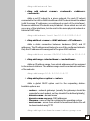
4.3.24.
snmp
The “snmp” command is used to configure the SNMP (Simple
Network Management Protocol) support. It has following syntax:
¡ snmp - shows current settings:
Tahoe> snmp
SNMP on
Read community: public
Write community: private
24
4.3.24
SNMP host1: <any>
SNMP host2: <disabled>
SNMP host3: <disabled>
¡ snmp on - enables SNMP support
¡ snmp off - disables SNMP support
¡ snmp rdcomm <text> - sets the read community - the
password used to read the SNMP parameters
¡ snmp wrcomm <text> - sets the write community - the
password used to write the SNMP parameters
¡ snmp host1 <address>
¡ snmp host2 <address>
¡ snmp host3 <address> - allows setting of up to 3 addresses,
from which the SNMP access will be permited. Entering 0.0.0.0
allows access from any address, while 255.255.255.255 disables
an entry (entering 255.255.255.255 in all three positions is equal
to disabling the SNMP service)
4.3.25
4.3.25.
strictarp
The “strictarp” command helps protecting the LAN against the
unauthorized access. After enabling the “strictarp” mode (by typing
”strictarp on”) and entering the static IP-MAC assignments (using “arp
add”) the modem would listen to incoming ARP requests asking for the
addresses it has in its static table. If the request comes from another
MAC address than in the modem’s ARP table, it will send an answer with
the correct MAC address.
Such request is sent by the PCs working under the Microsoft®
Windows™ operating system during the boot-up. If the ARP reply from
the modem comes, the PC will show a message that this address is
occupied, which will make an illegal use of that IP address impossible.
The “strictarp” mode may be disabled using “strictarp off”.
4.3.26
4.3.26.
syslog
The modem may send the messages about its status and
important events to a syslog server. To configure syslog logging following
commands may be used:
¡ syslog on - enables logging
¡ syslog off - disables logging
¡ syslog host <IP address> - sets the IP address to which the
messages will be sent
25
4.3.27.
telnet
4.3.27
The command allows limiting the telnet access to the modem.
The access may be enabled or disabled by entering “telnet on” or
“telnet off”, respectively.
Moreover the access may be limited to a certain IP address:
telnet host <IP address>
If the IP address is set as 0.0.0.0, then the access is possible from
anywhere in the network.
4.3.28.
tftp
4.3.28
The command configures the TFTP server used for the firmware
upgrade. Three options are possible:
¡ tftp on - enables the TFTP server
¡ tftp off - disables the TFTP server
¡ tftp host <IP address> - if the server is enabled, the access to
it may be limited to a certain IP address. If this address is set to
0.0.0.0, then the access isn’t limited.
4.3.29.
timeout
4.3.29
The command sets the inactivity time (in seconds), after which
the telnet connection is closed. It has following syntax:
timeout <during the session> [<during logging in>]
The first parameter is used after the logging in and the second
one (optional) during the log-in. Entering “0” disables the timer.
These settings are also applied to the serial console if its access is
password protected (using the „console passwd on” command).
4.3.30.
uptime, w
Shows the time elapsed since the modem booting and the current
processor temperature.
26
4.3.30
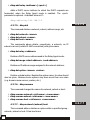
4.3.31
4.3.31.
user
The “user” command is used to manage users having access to
the modem. The modem may work in two different modes:
¡ single user - only the password is necessary to access the
modem. The user that logs in has the full access to the device.
¡ multiple users - allows creating many users with different
names, passwords and access levels
The “user” command has following syntax:
user list - shows the user list
user add <name> - adds a new user
user del <name> - removes an user
user passwd <name> <password> - changes the user’s
password
¡ user level <name> <access level> - changes the user’s
access level. The <access level> parameter may be one of:
§ admin - full access to the device
§ read-only - permits only reading of the configuration and the
statistics
¡ user mode { single | multi } - selects the working mode - to
either single or multi-user
¡
¡
¡
¡
4.3.32
4.3.32.
ver
Displays current firmware version.
4.3.33
4.3.33.
watchdog
The “watchdog” command gives additional control over the
modem’s unpredicted behavior (i.e. a misconfiguration disabling further
communication with the modem). The modem uses the “ping” command
to check the availability of certain IP addresses and reboots, if one of
them doesn’t answer.
The command has following syntax:
¡ watchdog on - enables the watchdog
¡ watchdog off - disables the watchdog
¡ watchdog <interval> <amount> <wait> <IP address>
[<additional IP address> ] - configures the watchdog. After
<interval> seconds the modem sends <amount> of pings to
the <IP address> (and the <additional IP address> if set)
27
waiting <wait> seconds after each of them. If there is no answer
for any of the pings sent to the first address or for any of the pings
sent to the second address, then the modem is rebooted.
4.3.34.
write
Saves the current configuration to the EEPROM and displays an
information about the EEPROM usage. If the configuration is to large to
be stored some settings should be deleted, like static ARP entries, DHCP
options, etc.
28
4.3.34
5
5.
Technical data
¡ processor:
Motorola PowerPC, 50MHz
¡ memory:
4MB SDRAM
¡ network protocols:
IP, TCP, UDP, ICMP, TFTP, SNMP, DHCP, BOOTP,
RFC-1490, PPP, Frame Relay, Cisco® HDLC,
IEEE 802.1q
¡ Frame Relay signaling:
ANSI T1.617 Annex A, ITU Q.933 Annex D, Cisco® LMI
¡ G.shdsl interface:
connector:
standards:
modulations:
RJ-11
ITU G.991.2 (G.shdsl)
ITU G.994.1 (G.hs)
TCPAM-32, TCPAM-16, TCPAM-8, TCPAM-4,
PAM-16, PAM-8, PAM-4, PAM-2
¡ throughput:
Tahoe 681:
Tahoe 682:
64 - 4864 kbps
128 - 9728 kbps
¡ Ethernet interface:
10/100Base-T, RJ-45 connector
¡ serial console:
RS-232, DB9/M connector
¡ dimensions:
200 mm (width) x 45 mm (height) x 130 mm (length)
¡ power supply:
Tahoe 681:
15 V, 260 mA, 3,5W
Tahoe 682:
15 V, 360 mA, 5W
external power supply included
¡ environmental conditions:
storage:
operation:
temperature
humidity
temperature
humidity
-20°C to 65°C
5 to 95%
0°C to 40°C
0 to 85%
29
6.
6
Declaration of Conformity
TAHOE
Piotr Kaczmarzyk
ul. Uniwersytecka 1
50-951 Wroclaw, Poland
We declare that the products Tahoe 681 and Tahoe 682 comply
with the regulations of the following European Directives:
¡ 73/23/EEC
¡ 89/336/EEC
¡ 99/5/EEC
low voltage safety requirements
EMC requirements
radio & telecommunication
equipment requirements
terminal
The compliance of Tahoe 681 and Tahoe 682 with the
requirements of the above mentioned directives is ensured by complete
application of the following harmonized European Standards:
¡
¡
¡
¡
EN 60950:2000
EN 55022:1998
EN 61000-6-1:2002
EN 61000-6-3:2002
Signed:
Position:
Piotr Kaczmarzyk
Director
Signature:
Date:
Place:
30 Apr 2004
Wroclaw, Poland
©2004 Tahoe®. All rights reserved.
Other trademarks of other companies are used only for explanation and to
the owner's benefit, without intent to infringe.
Tahoe® assumes no responsibility for any errors or omissions that may appear in
this document. Tahoe® makes no commitment to update the information
contained here, and may make changes at any time without notice.
30
TAHOE®
Uniwersytecka 1
50951 Wroc³aw, Poland
phone +48 50 100 7362
fax +48 71 344 2642
http://www.tahoe-group.com/