Download February 2015 Wayne Electric Shop Intrusion Page 1 of 17 WAYNE
Transcript
February 2015
WAYNE JUNCTION CAR SHOP
INTRUSION DETECTION SYSTEM
PART 1 GENERAL
1.01
DESCRIPTION
A.
All of the work within this project shall be at SEPTA’s Wayne Electric Car Shop located
at 4500 Germantown Ave., Philadelphia, PA.
B.
The Contractor shall design and install a completely functional Intrusion Alarm System,
in full compliance with all codes, regulations, SEPTA Standards and guidance as
stated in this scope of work.
C.
The Fire Alarm System shall include but not be limited to: control panel, power supply,
remote power supplies, alarm initiating and notification devices, connections to
supplementary systems, conduit, wire and accessories to provide a complete and fully
operational system.
D.
The intent of this project is to provide intrusion detection at all the exterior man doors
and overhead bay doors in the locations shown in the attached building drawing.
E.
Contractor shall thoroughly instruct and has the responsibility to fully inform all their
workers and agents of the fact that they are working next to adjacent active rail
maintenance shops. Proper safety precautions must be taken by the Contractor to
prevent accidents. Contractor employees and their supervisor must attend and
successfully complete Railroad "Track Safety" safety class prior to any work starting at
the railroad job sites.
F.
This maintenance shop building is occupied therefore work will need to be coordinated
with daily work activities in this location.
G.
The Contractor is to furnish and install new intrusion devices in the locations shown on
the attached drawings.
H.
The Intrusion System shall be non-proprietary. The alarm equipment must be readily
available for purchase, installation and service, by any reputable contractor regularly
engaged in the burglar/intrusion alarm installation and service business. Additionally,
the equipment must be capable of being readily monitored, without losing type alarm
(intrusion, supervisory, and trouble) and specific zone or point, by any non-proprietary
receiver. Further, replacement parts and system training must be readily available at a
reasonable cost to whoever maintains the alarm equipment for SEPTA. This may
include SEPTA personnel or a third party contractor.
I.
If required, Contractor shall apply for permits with the City of Philadelphia.
J.
The Alarm contractor shall submit, for SEPTA approval, all of the specific Intrusion
Devices that will be used in this contract. The Contractor is expected to ensure high
quality in all components of the system that are specified.
Wayne Electric Shop Intrusion
Page 1 of 17
February 2015
1.02
REFERENCES
A.
B.
1.03
Underwriters Laboratories (UL):
1.
UL385 - Grades A, AA Police Connect.
2.
UL609 - Grade A Local Mercantile Premises and Mercantile Safe and Vault.
3.
UL611/UL610 - Grades A, AA Central Station.
4.
UL684 - Local, Central Station, and Remote Station.
Federal Communications Commission (FCC):
1.
FCC Part 15
2.
FCC Part 68
SYSTEM DESCRIPTION
A.
1.04
Provide a and Burglary/Intrusion Alarm System that includes the following capabilities:
1.
Commercial UL listed system.
2.
Supporting up to 32 zones.
3.
Interfacing with: an alpha numeric paging device.
4.
Operating with a long-range radio unit.
5.
Operating with an integrated security and access control systems.
6.
Supporting zone for supervision of peripheral devices.
7.
A scheduling capability to allow for automated operations.
SUBMITTALS
A.
1.05
Submittals shall include manufacturer data sheets for all major system components.
QUALITY ASSURANCE
A.
1.06
K.
The alarm manufacture shall be certified as being compliant with lSO900l.
VISIT TO JOB SITE
It is the contractor's responsibility to familiarize himself/herself with the existing
conditions of the shops. The acceptance of this bid shall presuppose the contractor's
entire familiarity with the conditions, and no extra cost will be allowed due to the
contractor having failed to visit the sites and to note the conditions affecting the work.
Wayne Electric Shop Intrusion
Page 2 of 17
February 2015
1.07
A.
1.08
SCHEDULING
Work shall commence immediately upon award of Notice To Proceed.
NON-PERFORMANCE BY CONTRACTOR
A.
If the contractor fails to perform services in accordance with contract requirements,
SEPTA shall obtain those services through other means including the use of internal
resources or issuing a contract or purchase order to another contractor for the
services.
B.
Additionally, SEPTA's increased cost to have the service performed by other means
will be deducted from the Contractor's invoice.
1.09
DUTY TO INFORM EMPLOYEES OF CONDITIONS
A.
The contractor shall thoroughly instruct and has the responsibility to fully inform all
his/her workers and agents of the fact that they are working adjacent to active rail
maintenance tracks and high voltage.
B.
Contractors employees, and their supervisor, who work on the job site must attend
SEPTA’s Roadway Worker track Safety Class (not required if workers already have
current certification, 8 hours class time for an initial certification, 4 hours class time if a
renewal) and attend a shop safety briefing (4 hours). Attendance at these classes and
in the SEPTA facility requires SEPTA approved vests and flashlights. Attendance and
equipment is at the Contractor’s cost.
1.10
CLEARANCES
The contractor must conduct all of his operations in connection with this contract so
that no part of his equipment (including ladders) may foul an operating or maintenance
track, electrical transmission, or communication lines or damage any others.
1.11
WORKMANSHIP
A. The contractor shall supply all necessary tools, equipment, and material required
for the accomplishment of this contract.
B. Competent personnel under the supervision and employment of the contractor shall
perform all work. The contractor, and all parties employed on the work, shall
perform their work in a good and workmanlike manner. The contractor must furnish
labor, which can work in harmony with all other elements of labor employed or to be
employed by the Authority.
C. The contractor must take all steps necessary to minimize interference with the
normal operation of the station.
D. The contractor must remove and dispose of all trash from the installation.
E. Contractor shall clean up any construction related debris on the job site upon
completion of the individual task that generated the debris.
F. Work area must be cleaned of all work debris at the end of each work day.
Wayne Electric Shop Intrusion
Page 3 of 17
February 2015
1.12
ACCIDENTS OR INCIDENTS
A.
1.13
Any accidents or incidents occurring to the contractor's employees while
performing work for this contract on SEPTA premises must be immediately
reported to SEPTA's Project Manager or his designee. A follow-up written report
must be submitted to the Project Manager or his designee within 24 hours of the
accident or incident.
WARRANTY
A.
All major Intrusion Alarm equipment shall be installed, adjusted and serviced by
authorized representatives of the equipment manufacturers.
B.
The Contractor shall warrant the entire system and each of the individual components
of the system. All system components warranty must be for a minimum of one (1) year.
The warranty shall require the Contractor to provide all equipment, material, and labor
at no charge to SEPTA during the warranty period.
C.
All manufacturers’ warranties shall be in SEPTA’s name. If the Contractor modifies any
equipment to void any manufacturer’s warranty, the Contractor shall provide a
warranty equivalent to that of the original manufacturer’s warranty.
D.
The Contractor shall provide a, maximum, two-hour response time for service calls
during the warranty period.
E.
The Warranty period starts the day when the SEPTA 3rd Party Burglar/Intrusion/Fire
Alarm Maintenance, Monitoring and Inspection Co. has accepted the intrusion alarm
system to their central monitoring station.
PART 2 PRODUCTS
2.01
SYSTEM PERFORMANCE
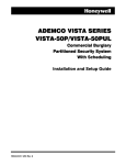
A. The Main Burglar/Intrusion Control Panel shall be an ADEMCO VISTA 128BPT or
SEPTA approved equal.
1. The Control Panel must be an 8-partition unit, capable of supporting hardwire,
hardwire expansion and wireless zones. Peripheral devices supported by the
Control Panel shall include bells, cellular communicator, dialers (telephone lines),
keypads, RF receivers, and relays. The following minimum performance
requirements shall be met.
a. Basic Hardwire Zones - A total of 9 style-B hardwire zones shall be capable of
supporting the following:
i.
EOLR supervision supporting normally open (N.O.) or normally closed
(N.C.) sensors.
ii.
Individually assignable to one of 2 partitions.
iii.
Individually assignable to bell outputs and/or auxiliary relay.
Wayne Electric Shop Intrusion
Page 4 of 17
February 2015
b. Polling Loop Expansion Zones - The Control Panel shall also be capable of
supporting up to 24 additional hardwire zones using a built-in, 2-wire, polling
(addressable) loop interface. The polling loop shall provide power and data to
remote point modules, and constantly monitor the status of all zones on the
loop. The polling loop zones shall be capable of:
i. Using Remote Point Module (RPM) devices.
ii. Providing individual point addresses for each intrusion point (unless
otherwise directed in the contract documents).
iii. Supervision by the Control Panel.
iv. Individually assignable to one of the partitions.
v. Individually assignable to bell outputs and/or auxiliary relay.
vi. 4,000-foot capability without shielded cable.
c. Partitions - The independent partitions shall provide the following features:
i.
A Common Lobby partition shall be capable of automatic arming, when the
last partition sharing the lobby is armed, and automatically disarmed when
the first partition sharing the common lobby is disarmed.
ii.
A Master Partition shall be provided for assigning keypads capable of
simultaneously viewing the system status of both partitions.
iii.
Both partitions shall be capable of having keypads assigned.
iv.
Both partitions shall be capable of supporting relays.
v.
The ability to display burglary and panic and/or trouble conditions at all
other partition keypads shall be optional.
vi.
The ability to support selectable options including entry/exit delay and
subscriber account in formation.
d. User Codes - The Control Panel shall accommodate 75 user codes. The
following characteristics shall be assigned to each user code.
i.
Authority level
ii.
Partitions operated by the user code
iii.
Optional opening/closing central station reporting
Wayne Electric Shop Intrusion
Page 5 of 17
February 2015
e. Peripheral Devices - The Control Panel shall support up to 16 addressable
devices. The devices shall include any combination of keypads, RF receivers,
relay modules, notification circuit modules and access control modules.
Peripheral devices shall have the following characteristics: Each device shall
be:
f.
i.
Physically set to an individual address.
ii.
Enables using the Device Programming Mode.
Remote Keypads - The Control Panel shall be compatible with remote keypads
and allow the user to:
i.
Arm and disarm the entire system or one partition in a multiple partition
system.
ii.
Bypass zones.
iii.
Display zone descriptors (alarm, trouble, bypass, etc.) in the display
window.
v.
Individually silence notification circuits and or reset panel.
g. Notification Output Circuits - The Control Panel shall internally provide two
supervised NAC outputs for operating fire and burglar alarm notification
appliances. It shall also support two additional supervised NAC outputs when
using a supervised NAC module. Each NAC output shall be rated at 10-14VDC,
1.7 amp max power limited. Total alarm current draw when using two NAC
outputs shall not exceed 2.3 amps for battery independent operation.
h. Auxiliary Relay - A built-in Form C relay shall be provided. The relay contacts
shall be rated at 28 VAC/VDC, 2.8 amps maximum. The relay shall support:
i.
i.
Alarm activation.
ii.
Trouble/supervisory activation.
iii.
Reset of 4-wire smoke detectors.
iv.
Battery saving feature.
Output Relays - A total of 16 relay outputs shall be accommodated using relay
modules. Each relay module shall provide four Form C (normally open and
normally closed) relays for general-purpose use or two Y-style supervised bell
outputs. The relay characteristics shall be capable of being:
i.
Programmed to activate in response to system events.
ii.
Programmed to activate using time intervals.
iii.
Used for additional y-style supervised be NAC outputs.
Wayne Electric Shop Intrusion
Page 6 of 17
February 2015
i.
iv.
Activated manually using a relay command mode.
v.
Supervised by control panel.
vi.
Assigned an alpha descriptor.
Addressable Loop Output Relay - A total of 16 Form C (normally open and
normally closed) shall be accommodated using the addressable detection loop
single relay module. The relay characteristics shall be capable of being:
i.
Programmed to activate in response to system events.
ii.
Programmed to activate using time intervals.
iii.
Used for additional y-style supervised be NAC outputs.
iv.
Activated manually using a relay command mode.
v.
Supervised by control panel.
vi.
Assigned an alpha descriptor.
k. Ancillary Control - The Control Panel shall be capable of being programmed to
activate up to 16 control relays which could open doors, turn on/off lights, etc.
l.
12-Volt Power Supply - The Control Panel shall have a 12-Volt power supply
transformer. The transformer shall supply a total of 2.3 amps total for both
panel notification circuits and ancillary functions.
i.
Alarm notification appliances, including but not limited to sirens and
strobes.
ii.
Power for relays, keypad/annunciators, 4 wire smoke detectors, access
control devices, etc.
m. Telephone Dialers - The Control Panel shall be equipped with a built-in
supervised telephone dialer for communications with the central station. It shall
also be capable of supporting a supervised backup dialer for connecting to a
second telephone line for commercial fire applications.
n. Trigger Output Connector * The Control Panel shall contain an internal
connector equipped for a single input and seven outputs. The outputs shall
interface with:
i.
Remote keypad sounder.
ii.
UL- Listed key switch.
iii.
LED indicator module.
iv.
Auxiliary alarm signaling equipment.
v.
Event logging serial printer.
vi.
Computer used to direct wire downloading via a serial module.
Wayne Electric Shop Intrusion
Page 7 of 17
February 2015
o. Voltage Triggers - The Control Panel shall provide a trigger outputs. The
trigger connector pins change state for different conditions in order to interface
with equipment such as long range radio equipment (LRR), remote keypad
sounders, and key switch ARMED and READY LEDs, or a system event log
printer.
p. Event Log - The Control Panel shall contain a programmable event log capable
of the following:
i.
Storing up to 224 events.
ii.
Viewable at the keypad,
iii.
Printed on a serial printer.
iv.
Storing access control system events.
v.
Sending printed events to an alphanumeric pager.
q. Scheduling - The Control Panel shall provide the following automated
scheduling capabilities:
r.
i.
Open/Close schedules used to control arming/disarming and reporting.
ii.
Holiday schedules, which allow different time windows for open/close
schedules.
iii.
Timed events which activate relays, auto-bypassing, un-bypassing, autoarming and disarming.
iv.
Access schedules, which limit system access to users, by name.
v.
End User Output Programming Mode shall provide 20 timers for relay
control.
Communication Formats - The Control Panel shall be able to communicate
Fire, Trouble, Supervisory and Contact ID signals back to the central
monitoring company (TycoIS) without the use of a separate communicator
device.
s. Audio Alarm Verification - The Control Panel shall support programmable audio
alarm verification (AAV) devices, capable of operating in conjunction with an
output relay, to permit two-way voice dialog between a central station operator
and the premises.
t.
Cross-Zoning Capability - In order to prevent false alarms, the Control Panel
shall prevent a zone from going into alarm, unless its cross-zone is also faulted
within 5 minutes.
Wayne Electric Shop Intrusion
Page 8 of 17
February 2015
u. Exit Error False Alarm Prevention -The Control Panel shall be capable of
differentiating between an actual alarm and a false one caused by leaving an
entry/exit door open. The Control Panel shall be capable of:
i.
ii.
Being arming while the faulted entry/exit zone(s) and/or interior zones are
bypassed.
Generating an Exit Error report by user and zone.
v.
Downloading Features - The Control Panel shall be capable of uploading and
downloading at 300 baud. It shall also be capable of uploading ECP devices,
their physical addresses, programmed addresses and firmware revision levels.
w.
Enhanced Walk-Test Mode - The Control Panel shall provide the installer with
the following features:
i.
Automatic test of all integrated remote point module (RPM) devices,
equipped with an automatic test feature.
ii. While automatic test is in progress all zones that remain untested shall be
displayed.
iii. An event log shall be capable of logging the results of tested and untested
zones.
iv. The ability to report the result of tested and untested zones to the central
station.
x.
Built-in User's Manual and Descriptor Review - A built-in User's Manual shall be
provided for End User convenience. The following shall be provided:
i.
z.
2.02
A brief explanation of keypad functions shall be provided at the keypad
alphanumeric display.
Access Control
i.
In addition, the Control Panel shall be capable of being connected to an
integrated access control systems.
ii.
The panel shall be capable of supporting three different methods of
wiegand access control card readers. These are by use of the ECP bus
or the V-Plex addressable loop.
ENCLOSURE
A.
The Control Panel shall be enclosed in a metal cabinet, suitable for wall mounting.
The dimensions shall not exceed 18 inches in height, 14.5 inches in width or 4.3
inches in depth.
Wayne Electric Shop Intrusion
Page 9 of 17
February 2015
2.03
ELECTRICAL POWER REQUIREMENT'S
A.
System Power - The Burglary/Intrusion Alarm System main control panel shall operate
using standard 120 volts AC, 60 Hz power.
1.
Control Primary Power - Transformer power shall be 18 VAC, 17VA.
2. Backup Battery - A rechargeable 12 VDC, gel type, lead acid backup battery shall
be provided. The battery shall be rated between 12 and 34-ampere hours (AH).
3. Alarm Power- Maximum alarm output power shall be 12 VDC, 1.7 amps for each
NAC output.
4. Auxiliary Standby Power - Standby power shall be 12 VDC, 1 amp maximum.
5. Total Power - Combined auxiliary standby and alarm currents shall be 2.3 amps.
6. Fusing - The battery input, auxiliary, and bell outputs shall be protected using PTC
circuit breakers. All outputs shall be power limited.
2.04.
A.
ENVIRONMENTAL CONDITIONS
Environmental Conditions - The Burglary Alarm System shall be designed
to meet the following environmental conditions.
1. Storage Temperature - The system shall be designed for a storage temperature of
100ºC to 700ºC.
2. Operating Temperature - The system shall be designed for an operating
temperature of 0ºC to 50ºC (32ºF to 120ºF).
3. Humidity - The system shall be designed for normal operation in an 85% relative
humidity environment.
4. Electromagnetic Interference The system shall meet or exceed the requirements of
FCC Part 15, Class B devices, FCC Part 68, IEC EMC directive.
2.05.
A.
EQUIPMENT
The following equipment shall be provided as part of the Burglary/Intrusion Alarm
System:
1.
Horn – Honeywell/ Ademco 748LC - Dual Tone Siren with Low Current Draw or
SEPTA approved equal
2.
Strobes – Honeywell/ Ademco 112-113 or SEPTA approved equal. Strobe shall
be clear in color.
Outdoor Horn/Strobe – Weather proof style Honeywell/ Ademco, System Sensor,
Wheelock or Gentex or SEPTA approved equal.
Keypad/Annunciators - Ademco/Honeywell 6160 or SEPTA approved equal.
Door/Window Contact – Honeywell Heavy Duty style contacts or SEPTA
approved equal.
3.
4.
5.
Wayne Electric Shop Intrusion
Page 10 of 17
February 2015
6.
Overhead Garage Door Contacts – Sentrol 2300 Series (Wide Gap Style) or
SEPTA approved equal with a stainless steel armored cable “whip”. Floor
mounted contacts are not permitted.
B. All equipment/devices shall be installed in all locations as follows:
1.
2.
3.
4.
5.
6.
7.
2.06
A.
B.
Each overhead door throughout the building shall receive a single intrusion
contact.
Each single man door shall receive a single intrusion contact.
Each double door shall receive a single contact for EACH opening door.
There shalll be a horn and strobe installed at each single man door and each
double door location.
There shall be a horn and strobe installed half way between column line C,1
and C,17.
Install an outdoor horn and strobe outside of the man door located at column line
G,1.
There shall be a keypad installed inside the man door at column G,1 and a
second keypad installed on the door of the main intrusion panel.
INTRUSION SYSTEM PROGRAMMING
Entry/Exit Delay – Man door at column line G,1 shall have a 30 second entry and exit
time delay.
Intrusion detection
i. Each single man door and overhead contact shall have its own individual address.
ii. Double man door shall have an individual address for both doors. (Double door
contacts shall annunciate on a single address point.)
iii. If any one contact is breached/activated all of the horn and strobes and keypad
tone devices shall activate.
2.07
FIRE ALARM SYSTEM POWER, RACEWAY AND WIRING
A.
Intrusion wiring shall be permit to be run “free air”; only if it is installed no less than 10
feet above the finished floor. All free air cabling must be properly supported at least
every 10 feet. Any wiring installed below 10 feet must be installed in conduit per this
specification.
B.
Metal Conduit must be used for all device wiring where wiring is being brought down
from the main cable to the addressable module and final detection device(s).
C.
Design/Installation must provide for the complete labeling of the raceway and all
junction and pull boxes as “INTRUSION ALARM SYSTEM”. Labels must be
waterproof (peal-off type). Connection box labels should be octagon shaped and
measure 3” across. Conduit should be labeled at a minimum of every 20 feet; shorter
lengths of conduit between connection boxes should be labeled at the midway point.
Conduit labels should be rectangular shaped and measure ¾” wide by 5 ½” long.
Wayne Electric Shop Intrusion
Page 11 of 17
February 2015
D.
The raceway shall be installed in a manner that considers the effects of electrical and
Radio Frequency noise to prevent or minimize induced or electromagnetic
interference.
E.
Conduits and/or wiring shall not be installed less than 12 inches from any conduit or
exposed electrical bus work and/or distribution panel containing 480Volt or higher
voltage electrical conductors.
F.
Cast metal or plastic molded boxes (not sheet metal) shall be used for surface
mounting any device(s) to any exposed wall surface or support beam (i.e. in the
ceiling above shop areas, electrical substations, boiler rooms, etc.).
G.
Standard sheet metal (1900 Style) back boxes shall be permitted for use on nonsurface mounted devices for office areas.
H.
Existing conduits and/or suspended ceiling support systems cannot be used to mount
new conduits or device back boxes.
I.
The distance between connection (junction) boxes for the Intrusion Alarm system
shall not exceed 100 feet.
J.
All conduit shall be a minimum of ¾” (EMT) with compression fittings (set screw type
connectors are not permitted) and appropriately sized for the cable it will carry and
allow for 25% expansion. Non-fire alarm cable shall not be installed in any fire alarm
conduit.
K.
FMC (Flexible Metal Conduit) conduit shall be permitted to be used to connect all final
devices to a junction box or condelet box.
L.
Wiring to be mounted vertically on any wall within the building will need to be installed
in EMT conduit.
M.
Any/all penetration into the building shall be properly and professionally sealed to
prevent water/weather infiltration into the buildings.
N.
The Intrusion Alarm system notification circuit shall be a minimum of 16 gauge 2conductor; the initiating circuit shall be a minimum of 18 gauge 2 pair single jacketed
cable. Outer cable jacket rating shall be a minimum of Riser jacket rating
classification. Outer jacket color shall be Dark Blue or SEPTA approved alternate.
O.
Conductors and Wiring material and methods shall meet all NEC and local code
requirements.
P.
Wires shall be color-coded and labeled to allow zone identification at terminal and
junction locations. Zone identification labels must be of high quality and equal to the
3M ScotchCode Wire Marking Tape.
Q.
If the installation is located where it has an increased potential risk of damage from
vehicle damage or vandalism this portion of the conduit shall be required to be rigid
steel (EMT will not be permitted in these situations). Review these locations with the
project manager prior to procuring and installing conduits. Project Manager has the
right to have any section of EMT changed to Rigid Steel even if EMT has already
been installed and at no additional cost to SEPTA.
R.
If the installation is located in an area that requires an explosion proof system, the
installation should be in accordance with NFPA 69.
Wayne Electric Shop Intrusion
Page 12 of 17
February 2015
2.08
SURGE PROTECTION MODULES
A.
Provide surge protection for the incoming power to the intrusion alarm main panel and all
remote power supply panels. Protection device shall be mounted either in or adjacent to
each intrusion alarm panel and not at the electrical distribution panel serving the fire
alarm panel(s).
B.
The surge protection shall be a Ditek Model DTK-120SR Module or SEPTA approved
equivalent for incoming fire alarm panel power circuits.
C.
Surge protection shall be UL 497B Listed and be compatible with the FACP.
D.
Surge protection shall be installed in accordance with Manufacturer’s installation
instructions.
E.
Wire connections shall utilize screw terminal connections.
2.09
REMOTE ANNUNCIATOR
A.
Two remote annunciators shall be installed for the intrusion alarm system. One shall be
installed on the door of the main intrusion alarm panel. A second one shall be installed
at the at the main building entrance in the lobby at column line G,1.
B.
Remote annunciator shall be a Honeywell model 6160 or septa approved equal.
C.
Remote annunciator shall be UL Listed and FM Approved with the main intrusion panel.
D.
Remote annunciator shall indicate alarm, Trouble and Supervisory alarm status for each
monitored point.
E.
Remote annunciator shall have the ability to control the intrusion panel Acknowledge,
Silence and Reset alarm functions.
F.
Must have a minimum of 32 character display screen with English language messages.
2.10
SUPPLEMENTARY AND OTHER FIRE ALARM SYSTEM DEVICES
A.
If remote power supply modules are required they should be of the same manufacturer
of the intrusion alarm system main panel.
B.
The power module must have 6.0 amps of output power.
C.
They must have sealed lead acid or gel type batteries capable of powering the
connected load and have spare capacity to power a fully connected load for a minimum
of 1 hour.
D.
They must have built in battery chargers for sealed lead acid or gel type batteries with
automatic switchover to standby battery when AC power fails
Wayne Electric Shop Intrusion
Page 13 of 17
February 2015
PART 3 EXECUTION
3.01
A.
POWER WIRING
Contractor shall provide 120Volt volt power to the new intrusion alarm system main
panel and any other panel or devices as required to complete the system.
3.02
SYSTEM COMMUNICATION
The intrusion alarm system will a single dedicated telephone line to communicate with
the Central Monitoring Station. Contractor shall provide conduit and wiring back to the
designated communications room or cabinet as required to allow the new intrusion
alarm system the capability to communicate with the central monitoring.
3.03
MOUNTING OF EQUIPMENT AND DEVICES
A.
All equipment and intrusion devices must be secured by using screws and hollow walls
anchors as required. Double Sided Tape of any kind will not be permitted to anchor
any device and/or equipment to its mounting surface.
B.
Main Intrusion Alarm Panel shall be mounted in the second floor office area
immediately next to the existing fire alarm panel.
C.
Main Intrusion Alarm Panel shall have an independent keypad mounted on the door of
the main panel unless the Project Manager specifies it to be installed at another
location in the office area.
3.04
MONITORING AND ACCEPTANCE
A.
The contractor shall set this panel up to be monitored by individual zones. One zone
for intrusion entry/exit by the main entrance. Further breakdown of the zones may be
requested by the project manager and if requested these zones shall be programmed
at no additional cost to SEPTA. Each zone shall be required to report to the central
monitoring station independently.
B.
The contractor will be responsible for maintenance and response to alarms until the
newly installed Alarm system responsibility is turned over to SEPTA E,M,&C.
Acceptance will not take place until the Intrusion Alarm system is completely and
satisfactorily installed, the facility work is completed and documentation as contained in
this specification is provided to the SEPTA Project Manager.
C.
The equipment transferred from the Contractor to SEPTA must be free of dust, dirt,
metal shavings, etc.
D.
When ready for acceptance, the alarm contractor is to provide a separate overview
briefing to SEPTA management (to include but not limited to: User Group
representatives from E,M,&C Contract Services and Facilities) at a mutually agreed
time. This briefing will be followed by a “walk-through” of the system to physically view
the system devices and an activation of the Intrusion Alarm.
Wayne Electric Shop Intrusion
Page 14 of 17
E.
February 2015
At the above overview briefing, the contractor must supply SEPTA the below items and
documentation. All of the items must be formally and professionally presented to
SEPTA. Further, all items requiring signature must contain the printed or typed
signature block of the signatory.
1.
Provide installing contractor’s written statement stating that the system has been
installed in accordance with approved plans and tested in accordance with the
manufacturer’s specifications and the appropriate local code requirements.
2.
Provide a hardcopy and MSExcel versions of the zone list with its descriptions as
installed in the intrusion alarm system. (NOTE: Final Zone list descriptions must
be approved by the Project Manager prior to being installed in the intrusion alarm
system.)
3.
Provide a “Record of Alarm Inspection, Testing, and Certification.”
4.
Provide a copy of any require permits and approvals by the City of Philadelphia if
applicable.
5.
Provide a copy of the final electrical inspection performed on this installation.
6.
Provide a copy of UL certificates or FM placards.
7.
Provide four sets of all keys to the Alarm system panel.
8.
Provide copies of the user manual
9.
Provide a record of the installed Operating System Software (sometimes referred
to as firmware, BIOS, or Executive Program) and site-specific software (runs at a
level below the operating system software and is specific to the Alarm System
installation) version numbers.
10. Provide two copies of the site-specific software.
F.
Upon satisfactory completion of the acceptance requirements, the contractor shall
coordinate with SEPTA E, M & C Contract Services, the exact date of cut over of
system monitoring to the current burglar/intrusion fire alarm monitoring contractor.
Successful programming of the system to the 3rd party alarm monitoring contractor will
complete the acceptance process.
G.
Contractor shall provide qualified personnel to support the alarm system cut over to the
monitoring service.
3.05
A.
CUTTING AND PATCHING
Work included: This Section covers general requirements pertaining to cutting (including
excavating), fitting, and patching of the work required to:
1. Make the installation fit properly in the existing structure
2. Installing conduits
3. Uncover work to provide for installing, inspecting, or both.
4. Remove and replace work not conforming to requirements of the Contract
Documents; and
5. Removed and/or replace defective or changed work.
6. Coordinate the Work with other separate contractors.
7. Repair holes and cracks caused by selective Demolition and/or removal of
accessories and equipment.
Wayne Electric Shop Intrusion
Page 15 of 17
B.
C.
February 2015
Responsibilities: Contractor shall be responsible to perform their own cutting, fitting and
patching work for the components of this project.
Request for Approval: Prior to cutting any element, submit written request to the SEPTA
Project Manager for permission to proceed with cutting. The request shall include (but
not limited to) the following:
1
A description of the extent of cutting and patching required, the method for
performing the cutting and patching and an explanation for why cutting and patching
is required.
2.
Description of the anticipated results in terms of changes to existing construction,
including related changes to structural elements and functional components as well
as changes in the structure's appearance and other significant visual elements.
3.
A list of products to be used and firms or entities that will perform work.
D.
Areas to be cut and/or drilled that are exposed to publicly visible or in occupied spaces
shall not be cut or patched in a manner that would, in the opinion of SEPTA's Project
Manager, negatively affect the aesthetic qualities of the building's structural and
architectural elements or result in permanent, visual evidence of cutting and patching.
The responsible Contractor shall remove and replace work cut and patched in a manner
deemed to be visually unsatisfactory by any of the above parties.
E.
Cut holes and slots neatly to the size required with minimum disturbance of adjacent
surfaces. Temporarily cover openings when not in use.
F.
Restore all patched areas in a manner to eliminate evidence of patching.
G. Do not cut and patch operational elements or safety related components in a manner
that would result in a reduction of their capacity to perform in the manner intended, or
that would result in increased maintenance, or decreased operational life and/or
decreased safety.
3.06
SITE AND EQUIPMENT CLEAN UP
Contractor shall clean up any debris left at the site due to their construction efforts (i.e.
packing materials from products used, concrete dust from core drilling holes and/or
anchors, metal shavings from drilling into metallic material, etc.)
3.07
INTRUSION ALARM MONITORING CUTOVER
Contractor shall be responsible for the payment to the current burglar/intrusion alarm
monitoring company (TYCOIS) for the final installation of this intrusion alarm system to
their monitoring system and database.
The Contractor shall be solely responsible for coordinating with TYCOIS and confirming
that their monitoring practices and protocols are compliant with the intrusion alarm
system design and final installation.
Contractor shall be responsible for coordinating the installation with the SEPTA Project
Manager and the alarm monitoring company (TYCOIS).
Wayne Electric Shop Intrusion
Page 16 of 17
February 2015
3.08
INVOICING
A.
Contractor shall submit payment at 100% of project completion to be approved by the
Project Manager and/or their designee prior to final approval for payment. No interim
payments shall be permitted.
B.
Invoice shall be mailed to SEPTA, ATTN: Robert J. Tangi, 12th Floor, 1234 Market
Street, Philadelphia, PA 19107.
END OF SPECIFICATION
Wayne Electric Shop Intrusion
Page 17 of 17


