1
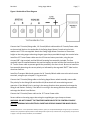
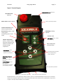
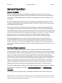
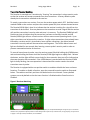
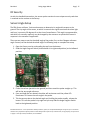
Remote Control Swing Auger Mover Installation and Operating Manual The Remote Control Swing Auger Mover is designed to provide the ultimate in convenience and safety to perform tasks remotely. It is a radio frequency (RF) controlled device that allows operation of a motor, gate, chute, etc. from a hand held transmitter operated remotely. The Transmitter, which operates at 916 MHz FM, transmits encoded information to the Receiver, which then decodes the information and performs the desired function. When coupled with the electromechanical driver, this system may be used to operate a motor, open a swinging gate, close a chute, turn a valve, etc. The Transmitter and Receiver are designed to operate within 300' but actual range is dependent on operating environment. Features: Simplicity of design and quality of engineering. Power On/Off switch on Receiver Console Direction Control switch on Console LED Indicator lights. 9v Transmitter Battery Ease of installation/removal when not in use. All controls can be by either Manual Switch or Remote Control Multiple Transmitters can operate a single Receiver. Multiple Receivers can be operated by a single Transmitter. Receivers are “Channel selectable” Optional Auxiliary 12VDC output for remote-controlled light or other device Table of Contents Specifications................................................................................................................................................ 2 FCC ................................................................................................................................................................ 3 Industry Canada ........................................................................................................................................... 3 Installation Instructions ............................................................................................................................... 4 Mechanical Installation ............................................................................................................................ 4 Electric Cylinder Installation .................................................................................................................... 5 General Operation........................................................................................................................................ 9 Control Console ........................................................................................................................................ 9 Auxiliary Output (option) ......................................................................................................................... 9 Transmitter/Receiver Matching ............................................................................................................ 10 Channel Select Settings .......................................................................................................................... 11 Transmitter ............................................................................................................................................. 11 Transport Winch (option)....................................................................................................................... 12 Full Bin Alarm (option) ............................................................................................................................... 13 Mechanical Installation .............................................................................................................................. 14 Sensor Probe........................................................................................................................................... 14 Electrical Installation .................................................................................................................................. 14 Sensor Probe........................................................................................................................................... 14 General Operation...................................................................................................................................... 15 Receiver Console .................................................................................................................................... 15 Limited Warranty ....................................................................................................................................... 19 Figure 1 Figure 2 Figure 3 Figure 4 Figure 5 Figure 6 Figure 7 Figure 8 Mechanical Assembly Drawing ..................................................................................................... 4 Mounting Position ......................................................................................................................... 5 Cable Diagram ............................................................................................................................... 6 Underside of Case Diagram ........................................................................................................... 7 Console Diagram ........................................................................................................................... 8 Receiver Matching ....................................................................................................................... 10 Full Bin Alarm (option) U-Bolt Diagram ...................................................................................... 14 Receiver Console Diagram .......................................................................................................... 15 Kramble Industries Inc. is not responsible or liable for indirect, special, or consequential damages arising out of or in connection with the use or performance of the product or other damage with respect to any economic loss, loss of property, loss of revenue or profit, or costs of removal, installation, or reinstallation. Specifications Transmitter: Power: Frequency: Modulation: Indicators: Case Size: Weight: Range: Antenna: Security Code: Safety: Functions: 9 Volt DC Battery 916 MHz FM Power/Transmit Red LED 2.5” x 4.2” x .8” .25lb 300’ + (depending on environment) 1.3” Fixed Mini Tuned Unique in each Transmitter Off / Standby Slide Switch 2 to 9 Button (depending on model) Receiver: Power in: Power out: Standby: Power Input: Indicators: Options: Antenna 12 VDC 12 VDC @ 10 amps max 40mA 4ga 2conductor wire with “powerpole” connectors Power on red LED Channel active green LED Receive/Learn RF Data Yellow LED Multi-Channel Operation (1-4) Main Power On/Off Switch Manual Switch Control 3” Flexible Tuned Electric Motor Drive Electrical: Torque: Speed: Output Shaft: Duty Cycle: Overall Size: Weight: 12vdc @ 100A Full Load 1125 in-lb 60 rpm no load ¾” keyed and drilled 5% 4” x 6” x 15” 16lb Revision 1 Swing Auger Mover Page | 3 FCC This equipment has been tested and found to comply with the limits for a Class B digital device, pursuant to part 15 of the FCC Rules. These limits are designed to provide reasonable protection against harmful interference in a residential installation. This equipment generates, uses and can radiate radio frequency energy, and if not installed and used in accordance with the instructions, may cause harmful interference to radio communications. However, there is no guarantee that interference will not occur in a particular installation. If this equipment does cause harmful interference to radio or television reception, which can be determined by turning the equipment OFF and ON, the user is encouraged to try to correct the interference by one or more of the following measures: Reorient or relocate the receiving antenna. Increase the separation between the equipment and receiver. Connect the equipment into an outlet on a circuit different from that to which the receiver is connected. Consult the dealer or an experienced radio/TV technician for help. Industry Canada This device complies with Industry Canada license exempt RSS standard(s). Operation is subject to the following two conditions: (1) this device may not cause interference, and (2) this device must accept any interference, including interference that may cause undesired operation of the device. Le présent appareil est conforme aux CNR d'Industrie Canada applicables aux appareils radio exempts de licence. L'exploitation est autorisée aux deux conditions suivantes: (1) l'appareil ne doit pas produire de brouillage, et (2) l'utilisateur de l'appareil doit accepter tout brouillage radioélectrique subi, même si le brouillage est susceptible d'en compromettre le fonctionnement. Kramble Industries Inc. 102-2750 Faithfull Ave. Saskatoon, SK S7K 6M6 306-933-2655 [email protected] www.kramble.net Kramble Industries Inc. is not responsible or liable for indirect, special, or consequential damages arising out of or in connection with the use or performance of the product or other damage with respect to any economic loss, loss of property, loss of revenue or profit, or costs of removal, installation, or reinstallation. Revision 1 Swing Auger Mover Page | 4 Figure 1 Mechanical Assembly Drawing Installation Instructions Mechanical Installation The Swing Auger Mover is designed to clamp directly onto the swing auger tube at the lowest point. Using the six 7/16 x 2-1/2” bolts provided, tighten the clamp around the tube such that the main beam is horizontal when the hopper is on level ground and the auger is at its normal working height. Clamps are available for 10”, 12”, 13”, 14” and 16” Augers. Kramble Industries Inc. is not responsible or liable for indirect, special, or consequential damages arising out of or in connection with the use or performance of the product or other damage with respect to any economic loss, loss of property, loss of revenue or profit, or costs of removal, installation, or reinstallation. Revision 1 Swing Auger Mover Page | 5 Figure 2 Mounting Position Clamp the Swing Auger Mover Drive at the lowest point possible on the swing auger tube so that, on level ground, the Main Beam is level without extending the jack, and all of the weight is off the inside wheels of hopper. There is a grease nipple located on each axle sleeve. Grease before first operation and thereafter, as needed. Electric Cylinder Installation The Swing Auger Mover is provided with pre-cut wire lengths with color-coded connectors attached. Cable Schedule: Tractor Power Cable - 12’ c/w Red/Black PowerPole Connector. Console Power Cable - 9’ c/w Red/Black PowerPole Connector Console/Swing Cable - 6’ c/w Black/Black PowerPole Connector Console/Winch Cable - 14’ c/w ¼” Ring Terminals Kramble Industries Inc. is not responsible or liable for indirect, special, or consequential damages arising out of or in connection with the use or performance of the product or other damage with respect to any economic loss, loss of property, loss of revenue or profit, or costs of removal, installation, or reinstallation. Revision 1 Swing Auger Mover Page | 6 Figure 3 Cable Diagram The polarity must be correct as follows: +12v on the RED STRIPE wire on the POWER CABLES FROM THE TRACTOR TO THE CONTROL CONSOLE. The RED /BLACK connector shells MUST MATCH. WARNING: DO NOT ATTEMPT TO POWER THE CONSOLE OR DRIVE FROM A BATTERY CHARGER ALONE AS DAMAGE MAY OCCUR. CONNECT TO A PROPERLY MAINTAINED BATTERY SYSTEM ONLY. Kramble Industries Inc. is not responsible or liable for indirect, special, or consequential damages arising out of or in connection with the use or performance of the product or other damage with respect to any economic loss, loss of property, loss of revenue or profit, or costs of removal, installation, or reinstallation. Revision 1 Swing Auger Mover Page | 7 Figure 4 Underside of Case Diagram Connect the 6’ Console/Swing cable, 14’ Console/Winch cable and the 9’ Console/Power cable to the terminal block on the underside of the Swing Auger Mover Console using the lock washers and ¼”-20 nuts supplied. Attach the Swing Auger Mover Console at a convenient height on the swing auger tube using the gear type clamps provided through the console holes. Install the 12’ Tractor Power cable onto the 12V tractor battery terminals, using the precrimped 3/8” ring terminals and the 80A self resetting fuse assembly included. The fuse assembly must be installed between the positive battery terminal and the Red conductor of the 12’ Tractor Power cable to protect against the possibility of a short circuit. Be sure to install the fuse assembly observing the correct polarity as indicated by the engraved “BATT” label on the aluminum fuse bar. Install the Transport Winch and connect the 14’ Console/Winch cable onto to the winch motor terminals, using the pre-crimped ¼” ring terminals. Connect the 6’ Console/Swing cable to the Swing Auger Mover wheel assembly motor cable. The polarity for the Swing A/B and the Winch A/B terminals will reverse during normal operation. If the Wheel Drive is running in the wrong direction when operated, exchange the Swing A and B wires. Similarly, if the Winch is running in the wrong direction when operated, exchange the Winch A and B wires. Connect the 9’ Console/Power cable to the 12’ Tractor Power cable. Secure cables to the swing auger tube using the supplied gear type clamps as shown. WARNING: DO NOT CONNECT THE TRACTOR POWER CABLES TO THE CONTROL CONSOLE OUTPUT TERMINALS AS AN ELECTRICAL SHORT AND SERIOUS DAMAGE OR INJURY COULD RESULT! Kramble Industries Inc. is not responsible or liable for indirect, special, or consequential damages arising out of or in connection with the use or performance of the product or other damage with respect to any economic loss, loss of property, loss of revenue or profit, or costs of removal, installation, or reinstallation. Revision 1 Swing Auger Mover Page | 8 Figure 5 Console Diagram Audible 95dB Alarm (optional) LED Visible Alarm (optional) Gear Type Clamp location Master Power PUSH to operate Indicator LEDs Power (red) – Power On/System Ready FBA Power PUSH to operate Receive/Learn (yellow) – Data receiving from transmitter/system in learn mode Indicator LEDs FBA POWER (Red) – Power On / FBA Ready Indicator LEDs Output (Green) – Power to motor / fault states indicator (slow blink for low battery and fast blink for high temperature LOW BATTERY (Green) – FBA Cancel/PUSH Sensor battery needs toreplacing silence alarm Learn Control – Hold during powerup to match to a transmitter Transport Winch Direction Control Momentary – Hold to operate Swing Motor Direction Control Momentary – Hold to Operate Auxiliary Output – Press both buttons simultaneously to toggle +12V Auxiliary output Gear Type Clamp location Auxiliary +12V output (optional) Entry access for Power and Drive cables Kramble Industries Inc. is not responsible or liable for indirect, special, or consequential damages arising out of or in connection with the use or performance of the product or other damage with respect to any economic loss, loss of property, loss of revenue or profit, or costs of removal, installation, or reinstallation. Revision 1 Swing Auger Mover Page | 9 General Operation Control Console The Control Console contains the radio Receiver and power control circuits. The Control Console is equipped with a Master Power On/Off switch on the outside of the case. When the switch is ON, the Red LED should be lit indicating normal operation. Press and release to turn On and Off. Each of the Swing Auger Drive and Winch may be operated independently from the Control Console by pressing the desired momentary switch. The Green “Output” LED will come on and the selected device will operate. The Control Console also has built-in fault status indicators. For ease of troubleshooting, if a “low voltage” status occurs to the Control Console, the green Fault States Indicator will blink approximately twice per second. Check all connections to ensure they are clean and tight. Make sure that the tractor battery is fully charged, and the engine is running. If a “control circuit high temperature” status occurs the green Fault States Indicator will flash rapidly, blinking approximately four times per second. Allow the unit to cool before resuming operation. Each Swing Auger Mover has its own RF receiver located in the control console, which is channel selectable to operate in multi-component environments e.g. remote control trailer chutes on Channels 1 & 2, and the Swing Auger Mover on Channel 3. The user can select the desired channel using the 2-position dip-switch. All Swing Auger Movers are set to Channel 1 at the factory. Auxiliary Output (option) The Control Console Auxiliary Output provides a remote control power output capable of delivering 10A (120 watts). This feature is intended for the operation of a remote control light for illuminating the work area when approaching at night, or for operation of a camera or other device. The output can be activated and deactivated from the transmitter by pressing the centre button on the RF transmitter (marked AUX), or from the Control Console by pressing the two “Aux” control buttons on the face of the Control Console simultaneously. The auxiliary output is protected by a thermal fuse that automatically resets when cooled. The auxiliary output is automatically shut off when the fuse trips to prevent a repeating cycle of the fuse tripping and resetting and must be reactivated using the transmitter or Console controls. The Auxiliary output option includes a 5-foot length of cable to connect the Control Console to the 12V device. The polarity is as follows: +12V on the WHITE wire, and GROUND on the BLACK wire. The auxiliary output connector is factory installed at the bottom center of the console case. Kramble Industries Inc. is not responsible or liable for indirect, special, or consequential damages arising out of or in connection with the use or performance of the product or other damage with respect to any economic loss, loss of property, loss of revenue or profit, or costs of removal, installation, or reinstallation. Revision 1 Swing Auger Mover Page | 10 Transmitter/Receiver Matching The Receiver is matched to a Transmitter by “learning” the transmitter’s unique security code so that the receiver will accept commands from that transmitter. A factory default system already has its transmitter matched to the receiver. To match a transmitter to a receiver, first turn the receiver power switch OFF. Hold the button marked LEARN on the receiver and press the receiver power ON, then release the two buttons. The Receive/LEARN light is then lit to indicate that the receiver is waiting for a signal from the transmitter to be learned. Press any button on the transmitter to send a signal and the receiver will read the transmitter’s security code and store it in memory. The Receive/LEARN light will flash three times to indicate that the transmitter has been successfully learned, and the Receive/LEARN light will turn off and receiver will then enter normal operating mode. Up to eight transmitters can be learned by a receiver. If eight unique transmitters have already been learned by a receiver and it is instructed to learn another transmitter, the oldest-learned transmitter’s security code will be overwritten and forgotten. The Full Bin Alarm buzzer and light are disabled for ten seconds after learning a sensor probe’s security code in order to prevent unwanted activation of the alarm. To erase all stored security codes, turn the receiver power ON while holding the LEARN button, and continue holding the button until the Receive/LEARN light begins to rapidly flash. Release the button, and the light will flash more slowly for three seconds, then turn off to indicate that the erase operation has succeeded. If the LEARN button is pressed while the Receive/LEARN light is slowly flashing, the erase operation is aborted and the receiver retains the stored transmitter security codes. The Receiver is equipped with a two-position switch to enable or disable the learn and erase functions. To enable or disable a function, open the case and locate the switch as illustrated below. The switches and their positions are labeled on the circuit board. Factory default systems are set by default so that the Learn function is Enabled and the Erase function is Disabled. Figure 6 Receiver Matching Kramble Industries Inc. is not responsible or liable for indirect, special, or consequential damages arising out of or in connection with the use or performance of the product or other damage with respect to any economic loss, loss of property, loss of revenue or profit, or costs of removal, installation, or reinstallation. Revision 1 Swing Auger Mover Page | 11 Channel Select Settings The Swing Auger Mover comes with a 2-position DIP Switch to match the Drive to the desired transmitter channel. In multi-component environments, be sure that each drive is set to a different channel so that devices do not operate simultaneously. Select the switch settings as follows: Channel 1 Channel 2 Channel 3 Channel 4 Switch 1 OFF ON OFF ON Switch 2 OFF OFF ON ON The Swing Auger Mover and Winch can be operated using the Transmitter, or alternatively, by operating the UP/DOWN momentary switches on the Control Console. Whenever the Swing Auger Mover drive or Winch is operated by remote control the Yellow “Receive Data” LED will be lit along with the Green LED indicating power output to the drive. The Swing Auger Mover has two automatically resetting fuses. Fuse F1 (1 Amp) inside the control console is intended to protect the RF receiver and data circuitry, and Fuse F2 (80 Amp) at the battery is intended to protect against a short circuit in the cables. These fuses will automatically reset when cooled. The Control Console power switch should be turned Off when not in use to prevent undesired operation. Transmitter The Transmitter is powered by a 9V battery which, when installed, should light the red "power" light when a switch is pressed. If the battery does not exceed 7 volts the Power light will not come On, indicating battery replacement is required. The Transmitter is also equipped with an OFF/Standby switch to prevent accidental operation. In the OFF position the transmitter Red LED will not light and the transmitter will not activate even when a function button is pressed. To operate, slide the switch to STANDBY. The transmitter remains off until a function button is pressed, at which time the Red LED will light and the transmitter will emit signal. No battery power is used when simply in Standby mode with no function buttons pressed. Each transmitter contains a unique identifying security code that is transmitted to the receiver during RF operation. Up to eight Transmitters can "talk" to the same Receiver as long as the receiver has learned the transmitters’ security codes. See page 9 for Security Code Matching Instructions. To access the battery, remove the 4 screws in the back of the Transmitter case and open the case. Kramble Industries Inc. is not responsible or liable for indirect, special, or consequential damages arising out of or in connection with the use or performance of the product or other damage with respect to any economic loss, loss of property, loss of revenue or profit, or costs of removal, installation, or reinstallation. Revision 1 Swing Auger Mover Page | 12 Transport Winch (option) The Transport Winch is provided for ease of lifting of the swing auger and hopper to and from the transport position. This electric winch operates on 12Vdc power provided through the Control Console and can be operated by manual switch on the Console, or by remote control. Think Safety! Do not install or operate where damage to persons or property may occur The customer can decide the optimum mounting location and utilization for each application. The electric winch may be employed to replace the existing hand-crank winch or alternatively, to operate in addition to the hand-crank winch. It is recommended to utilize the auger manufacturer’s pulleys and guides provided for the hand-crank winch to ensure the swing auger and hopper lifts as designed. In addition, remove any excess cable so as to reduce the number of cable layers on the winch drum and thus maximize capacity. To further increase winch capacity, a pulley block and hook can be utilized to effectively double the load capacity. To install the winch on the mounting plate provided, the customer should unwind the cable to get access to the two mounting holes, which are located underneath the drum. Unwind the cable until you have enough space to drop a bolt through each hole then screw the nuts on from the bottom. The Transport Winch option uses a Superwinch C1000 12vdc electric winch, which provides 5000lb. line pull (bottom layer) manufactured by Superwinch Inc. It is imperative for the user to follow all winching instructions as contained in the Superwinch Owner’s Manual. Think Safety! STAND CLEAR WHILE OPERATING AND ALWAYS USE SAFETY CHAIN WHEN RAISED Kramble Industries Inc. is not responsible or liable for indirect, special, or consequential damages arising out of or in connection with the use or performance of the product or other damage with respect to any economic loss, loss of property, loss of revenue or profit, or costs of removal, installation, or reinstallation. Revision 1 Swing Auger Mover Page | 13 Full Bin Alarm (option) The integrated Full Bin Alarm (FBA) is a monitoring system that indicates when the grain level in the bin is reaching its maximum. The system consists of a FBA console segment with audible and visible alarms built into the swing auger console and a sensor that hangs into the grain bin suspended from the spout of an auger. The battery-powered Sensor Probe is fully sealed and communicates wirelessly via radio frequency (RF) to the Receiver Console. When the grain level becomes high enough that the grain comes in contact with the Sensor Probe tilting it beyond 30° for 3 seconds, the sensor will send an RF signal that tells the receiver to activate the alarm. Kramble Industries Inc. is not responsible or liable for indirect, special, or consequential damages arising out of or in connection with the use or performance of the product or other damage with respect to any economic loss, loss of property, loss of revenue or profit, or costs of removal, installation, or reinstallation. Revision 1 Swing Auger Mover Page | 14 Mechanical Installation Sensor Probe The transmitter mounting kit contains a 12” chain, a U-bolt, two strap plates, four hex nuts, four flat washers, and two quick link connectors. Drill two ¼” holes 1-3/8” apart in the spout and attach the U-bolt as shown in the following figure. Use a quick link to attach the chain to the U-bolt and the second quick link to attach the chain to the Sensor Probe. The U-bolt may be mounted on the inside of the spout if space is limited. Figure 7 Full Bin Alarm (option) U-Bolt Diagram Electrical Installation Sensor Probe To install/change the battery, simply unscrew the top half off the Sensor Probe to reveal the circuit board and battery assembly. Unclip the battery connector and slide the battery out of the cable ties to remove. Insert the new battery in and clip the connector on. Perform the selftest described on page 15. Reassemble. NOTE: The Sensor is provided ready for operation with the 9v battery pre-installed and thus requires no external hook-up. Kramble Industries Inc. is not responsible or liable for indirect, special, or consequential damages arising out of or in connection with the use or performance of the product or other damage with respect to any economic loss, loss of property, loss of revenue or profit, or costs of removal, installation, or reinstallation. Revision 1 Swing Auger Mover Page | 15 General Operation Receiver Console The Full Bin Alarm Receiver Console is integrated into the front of the Swing Auger Mover console and is equipped with its own Power On/Off button and a Cancel Alarm (CAN) button on the face. The Swing Auger Mover must be powered on in order to use the Full Bin Alarm. The Full Bin Alarm powers on when the Swing Auger Mover is turned on, however, the Full Bin Alarm can also be powered off independently of the Swing Auger Mover to prevent undesired operation. Figure 8 Receiver Console Diagram Master Power PUSH to operate Indicator LEDs POWER (Red) – Power On/System Ready RECEIVE (Yellow) – Alarm signal receiving from sensor FBA Power - PUSH to operate Indicator LEDs FBA POWER (Red) – Power On / FBA Ready LOW BATTERY (Green) – Sensor battery needs replacing FBA Cancel PUSH to silence alarm The yellow LED indicates that the Console is receiving a valid RF transmission directed to the Bin Alarm. In normal operation, when the Sensor Probe is tilted more than 30° from vertical it transmits an alarm signal, which causes the Yellow “receive” LED to light for ½ second and the alarm to activate. The alarm signal is both a 2” RED lamp and audible beeper acting simultaneously. The green “low battery” LED illuminates when the sensor sends a Low Battery signal, indicating that the Sensor Probe battery requires replacement. Once activated, the green LED will remain on until the Bin Alarm is powered off. The Receiver Console activates the alarm when the alarm signal is received. The alarm remains on for ten seconds or until the Cancel button is pressed. If the Sensor Probe remains activated the alarm will continue for 60 seconds unless canceled. While the alarm is active but has been cancelled, the alarm can be reactivated by pressing the Cancel button a second time. If ten seconds pass without receiving an alarm signal and the alarm has been cancelled, the receiver will automatically reset to normal mode and sound the alarm again should the sensor subsequently transmit the alarm signal. Kramble Industries Inc. is not responsible or liable for indirect, special, or consequential damages arising out of or in connection with the use or performance of the product or other damage with respect to any economic loss, loss of property, loss of revenue or profit, or costs of removal, installation, or reinstallation. Revision 1 Swing Auger Mover Page | 16 The Full Bin Alarm power may be turned off independently of the Swing Auger Mover when not in use to prevent undesired operation. FBA Receiver Console SELF TEST To test the Receiver Console alarm light and siren, hold the Cancel button for four seconds while the Full Bin Alarm is powered on. Once tested, the alarm will shut off when the Cancel button is released. Sensor Probe A nine-volt battery powers the Sensor Probe. If the battery voltage falls below 6.5 volts, the transmitter will transmit a Low Battery signal approximately once per hour, which will illuminate the green LED on the receiver to indicate that the Sensor Probe battery needs replacing. If the battery voltage falls below 6.0 volts, the sensor will be unable to transmit. The Sensor Probe contains no external buttons or switches. Once the battery is installed it is always active. When the Sensor Probe is vertical, it is in very low-power sleep mode, waking every two seconds to check the tilt angle. A tilt angle greater than 30° will cause the sensor to remain awake and begin alarm transmission if the angle remains 30° for more than three seconds. While active, the Sensor Probe sends the alarm signal for a short period every five seconds. This is indicated by a blink of the yellow “receive” LED on the console. If the Sensor Probe remains tilted greater than 30° for more than one minute, transmission will cease and the Sensor Probe will return to sleep mode. Only when the Sensor Probe is returned to the vertical position, will it resume normal operation. Sensor Self-Test To test the battery level and threshold angle of the sensor, access the circuit board by unscrewing the top half and separating the two halves of the assembly. The circuit board and battery are mounted on the black sensor mounting plate. With the battery attached, hold the WHITE test button on the circuit board until the yellow LED lights up. If the yellow LED begins flashing, the battery is low and needs to be replaced. If the yellow LED stays on, the battery is good and it is always on while self-testing. To test the threshold angle the red LED will light up when the circuit board is tilted beyond the threshold. To exit test mode, hold the button again until the yellow LED remains off. The Full Bin Alarm Sensor Probe will not transmit a signal while in test mode. Ensure that the LEDs are not lit before reassembling the sensor. Kramble Industries Inc. is not responsible or liable for indirect, special, or consequential damages arising out of or in connection with the use or performance of the product or other damage with respect to any economic loss, loss of property, loss of revenue or profit, or costs of removal, installation, or reinstallation. Revision 1 Swing Auger Mover Page | 17 RF Security As with the handheld transmitter, the sensor probe contains its own unique security code that is matched to the receiver at the factory. Sensor Angle Setup The FBA Sensor utilizes a 3-axis accelerometer to determine its angle with respect to the ground. The trip angle of the sensor, at which it transmits the signal to activate the alarm light and horn, is preset to 30 degrees tilt at the time of manufacture. This angle is programmable, and while not normally required, may be changed by the customer to optimize the sensor’s response in the customer’s application. There are two steps to set the threshold angle of the probe; first, set the 0 degree reference angle. Second, set the desired threshold angle. Do following steps to complete the setup. 1. Open the Sensor case by unthreading the top from the bottom. 2. Slide the Angle Program Switch (shown below in its rightward position) to the leftward position. 3. Find a flat surface (parallel to the ground) and then stand the probe straight up. This will be the zero-angle reference. 4. Press and hold (do not release) the white self-test button until the yellow LED illuminates. This stores the zero angle in the probe. 5. Tilt the sensor probe to the desired angle and, holding the probe steadily, release the button. This sets the probe’s trip angle and you may slide the Angle Program Switch back to the rightward position. Kramble Industries Inc. is not responsible or liable for indirect, special, or consequential damages arising out of or in connection with the use or performance of the product or other damage with respect to any economic loss, loss of property, loss of revenue or profit, or costs of removal, installation, or reinstallation. Revision 1 Swing Auger Mover Page | 18 6. Test the sensor probe by tilting it back and forth to ensure proper operation. The red LED should illuminate when the threshold angle of the probe is reached. 7. To exit the self-test mode, hold the white self-test button until both yellow and red LED lights go out. Before the probe will transmit to the receiver, you must EXIT the self-test mode. 8. To test the probe with the receiver, power ON the FBA standalone console, Tilt the sensor probe over the threshold angle. Within 3-4 seconds the audio and visual alarms should activate. Kramble Industries Inc. is not responsible or liable for indirect, special, or consequential damages arising out of or in connection with the use or performance of the product or other damage with respect to any economic loss, loss of property, loss of revenue or profit, or costs of removal, installation, or reinstallation. Revision 1 Swing Auger Mover Page | 19 Limited Warranty Customer satisfaction is a fundamental policy at Kramble Industries Inc. All customers can rely upon and expect to receive prompt, efficient and courteous service on all Kramble Industries Inc. manufactured equipment from each and every employee of the organization. Kramble Industries Inc. with its office at 102-2750 Faithfull Avenue, Saskatoon, SK warrants: To the Original Purchaser/User, each product manufactured by Kramble Industries Inc. to be free from defective material and workmanship, under normal use and service, for a period of 12 months subject to conditions outlined below. The obligation under this warranty is limited to repair, or replacement with a similar genuine company part, for any part of the product of the company’s manufacture that is found to be defective. Warranty period begins the day of purchase. During the first (1st) through the twelfth (12th) month, Kramble will furnish without charge, F.O.B. its plant, a similar genuine part to replace any part of a product of the company’s manufacture which proves to be defective, in normal use and service, during this time. Labor to install or repair such parts will be absorbed by Kramble Industries Inc. If this work is to be done other than Kramble personnel, prior approval must be given by Kramble Industries Inc. as to rate and time. This warranty shall bind the company only as follows: 1. The warranty shall be limited to the repair or replacement of defective parts, all other damage, loss, cost or obligation and claim whatsoever, statutory or otherwise, are hereby waived by the original purchaser\user, and again, the warranty hereby given covers only those labor charges specifically authorized by the company in advance. 2. The warranty shall not apply to any failure, or damage incurred through neglect, lack of maintenance, misuse, abuse, accident, improper installation, re-designing of assemblies, ignorance, or through any other cause beyond the control of the company. 3. The warranty does not cover products of other manufacturers beyond such warranty as may be made by such manufacturer. 4. The warranty shall not apply to normal maintenance services, or to deterioration of appearance of items due to normal use and exposure. 5. The warranty shall not apply when the original purchaser/user has allowed repair and/or service work to be conducted on the product without authorization from the company. IMPORTANT NOTE: Before any warranty work is done, contact Kramble Industries Inc. for authorization. Failure to do so may result in denial of warranty. Kramble Industries Inc. is not responsible or liable for indirect, special, or consequential damages arising out of or in connection with the use or performance of the product or other damage with respect to any economic loss, loss of property, loss of revenue or profit, or costs of removal, installation, or reinstallation.