1
Service Manual
Stat Profile® Critical Care Xpress
Preface
Stat Profile Critical Care Xpress Service Manual
Nova Stat Profile® Critical Care Xpress Service Manual
Part Number and Ordering Information
The Stat Profile® Critical Care Xpress Service Manual (PN 33826) can be ordered from Nova
Biomedical Order Services. Write or call:
Nova Biomedical
200 Prospect Street
Waltham, MA 02454-9141
U.S.A.
Telephone:
1-800-458-5813
FAX:
(781) 893-6998 (in the U.S.A.) or
(781) 899-0417 (outside the U.S.A.)
Technical Assistance
For technical assistance, call Nova Biomedical Technical Services at:
Telephone:
1-800-545-NOVA or
(781) 894-0800
FAX:
(781) 894-0585
Trademarks and Patents
Stat Profile® is a registered trademark of Nova Biomedical.
The Stat Profile Critical Care Xpress Analyzer is covered by the following patents:
U.S. Patent No. 4,686,479, U.S. Patent No. 5,578,194.
Copyright
Printed in the U.S.A. Copyright 2005, Nova Biomedical, Waltham, MA 02454-9141.
i
Preface
ii
Stat Profile Critical Care Xpress Service Manual
Stat Profile Critical Care Xpress Service Manual
Contents
1
Introduction . . . . . . . . . . . . . . . . . . . . . . . . . . . . . . 1-1
1.1
1.2
1.3
1.4
2
The Analyzer......................................................................................................... 1-1
Operational ........................................................................................................... 1-2
Cautions and Hazards ........................................................................................... 1-3
Required tools ....................................................................................................... 1-4
Product Description . . . . . . . . . . . . . . . . . . . . . . . . . 2-1
2.1
2.2
Mechanical Assemblies ........................................................................................ 2-2
2.1.1 CO-Oximeter ............................................................................................ 2-4
2.1.2 ABG (Electrolyte, Metabolite, Blood Gas) .............................................. 2-4
Electronic Assemblies........................................................................................... 2-5
2.2.1 Power Distribution .................................................................................... 2-5
2.2.2 Spare Parts - Description/Part Number..................................................... 2-5
2.2.3 ABG Digital Control Board ...................................................................... 2-6
2.2.4 CO-Ox Digital Control Board/CPU/Analog Board ................................. 2-8
2.2.5 ABG CPU Board .................................................................................... 2-10
2.2.6 ABG Analog Boards ............................................................................... 2-11
2.2.7 Flowcell Interface Board ........................................................................ 2-12
2.2.8 Power Distribution Board ....................................................................... 2-13
2.2.9 Power Supply Assembly ......................................................................... 2-15
2.2.10 Power Entry Module ............................................................................... 2-15
2.2.11 Hard Disk Drive ...................................................................................... 2-16
2.2.12 R/W CD-ROM Drive .............................................................................. 2-16
PN 33826 Rev. B 9/2005
TOC-1
Table of Contents
3
Replacement Procedures . . . . . . . . . . . . . . . . . . . . . 3-1
3.1
3.2
3.3
3.4
3.5
3.6
3.7
3.8
3.9
3.10
3.11
3.12
3.13
3.14
3.15
3.16
3.17
3.18
3.19
3.20
3.21
3.22
TOC-2
Cover Removal ..................................................................................................... 3-1
Sensor Module ...................................................................................................... 3-5
Preheater ............................................................................................................... 3-6
Sensor Module Interface Board ............................................................................ 3-6
Analog Boards ...................................................................................................... 3-7
ABG Computer Board (CPU)............................................................................... 3-8
ABG CPU, CD Drive, and Hard Drive Assemblies ............................................. 3-8
Power Supply Assembly ..................................................................................... 3-11
Power Distribution Board ................................................................................... 3-11
Fluid Pack RMS Cables ...................................................................................... 3-12
Sampler Assembly .............................................................................................. 3-12
Capillary Adapter Light ...................................................................................... 3-13
Sampler Assembly Motors ................................................................................. 3-15
ABG Pump Assembly ......................................................................................... 3-15
ABG Rotary Valve (Cleaning and Replacement) ............................................... 3-16
Printer Assembly/ Printer Board ......................................................................... 3-17
Display Assembly ............................................................................................... 3-17
Door Alignment .................................................................................................. 3-20
CO-Oximeter Assemblies ................................................................................... 3-20
3.19.1 Lamp assembly ....................................................................................... 3-20
3.19.2 CO-Ox Fluid Deck Removal .................................................................. 3-22
3.19.3 Fluid Deck Mechanical Replacement. .................................................... 3-23
3.19.4 CO-Ox Pump Assembly ......................................................................... 3-24
3.19.5 CO-Oximeter Electronic Boards ............................................................ 3-24
Spectrophotometer Assembly ............................................................................. 3-25
CO-Oximeter Cuvette ......................................................................................... 3-26
Replacing the SO2 Amp Board ........................................................................... 3-27
PN 33826 Rev. B 9/2005
Stat Profile Critical Care Xpress Service Manual
4
Troubleshooting . . . . . . . . . . . . . . . . . . . . . . . . . . . 4-1
4.1
4.2
4.2
4.3
4.4
4.5
4.6
4.7
5
Limitations and Dependencies.............................................................................. 4-1
Operational Specifications .................................................................................... 4-2
Flow Troubleshooting ........................................................................................... 4-5
4.2.1 Instrument Flow Tests ............................................................................... 4-5
4.2.2 Operator Tests ........................................................................................... 4-6
4.2.3 COOX Flow Obstructions in the Flowpath. ............................................. 4-8
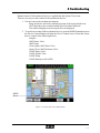
Service Menu ........................................................................................................ 4-9
4.3.1 System Test Screen ................................................................................. 4-10
4.3.2 Analog mv Display ................................................................................. 4-13
4.3.3 Service Flow Test.................................................................................... 4-14
4.3.4 Sensor Sub-Systems ............................................................................... 4-15
Resolving Flow Problems ................................................................................... 4-17
4.4.1 Clearing the Backflow Error code .......................................................... 4-17
4.4.2 General Flow troubleshooting ................................................................ 4-17
4.4.3 ABG Calibration Cycle .......................................................................... 4-18
4.4.4 ABG Sample Cycle ................................................................................ 4-18
4.4.5 Combined or CO-Oximeter Sampling Cycle.......................................... 4-19
4.4.6 Micro Sample Cycle ............................................................................... 4-20
Error Codes ......................................................................................................... 4-20
Resolving Results Problems ............................................................................... 4-21
4.6.1 Parameter Errors ..................................................................................... 4-21
4.6.2 Air Detector testing ................................................................................ 4-22
4.6.3 Calibration Standards Nominal Millivolt Differences ............................ 4-23
4.6.4 Analog Channel by Analyte .................................................................... 4-23
Power On Sequences .......................................................................................... 4-24
Adjustments and Maintenance Procedures . . . . . . . . 5-1
5.1
5.2
5.3
5.4
5.5
5.6
5.7
5.8
5.9
5.10
Installing Software Upgrades ............................................................................... 5-1
Touch Screen Calibration ..................................................................................... 5-3
Adding Peripheral devices .................................................................................... 5-3
Spectrophotometer: Optical Calibration ............................................................... 5-3
CO-Oximeter Lamp Intensity ............................................................................... 5-5
Internal Tube Replacement ................................................................................... 5-8
Rotary valve cleaning ......................................................................................... 5-10
Adding the Keypad Option ................................................................................. 5-13
Adding the Bar Code Reader .............................................................................. 5-14
Sampler/Syringe Adapter Alignment .................................................................. 5-14
PN 33826 Rev. B 9/2005
TOC-3
Table of Contents
A
Appendix . . . . . . . . . . . . . . . . . . . . . . . . . . . . . . . . A-1
A.1
Error Codes .......................................................................................................... A-1
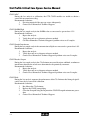
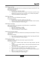
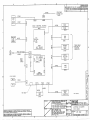
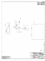
Drawings
Interconnect Diagram CCX NO COOX (Pg1)
Interconnect Diagram CCX NO COOX (Pg2)
Wiring Diagram CCX COOX
Calibration Tool PN20951
TOC-4
PN 33826 Rev. B 9/2005
1 Introduction
1
Introduction
This manual contains information and procedures used in servicing the Stat Profile CCX
Analyzer. The intent is to supplement the information provided in the CCX Instructions for
Use Manual (PN 39344) and the CCX Advanced User Applications Manual (PN 38343). This
manual does not supercede any current performance specification claims, expendable maintenance procedures, or warranty criteria as outlined in the reference manual.
1.1
The Analyzer
Environmental
Ambient Temperature: 15° - 32° C ( 59 ° - 86 ° F)
Ambient Humidity: 0% - 95% Non-condensing
Energy consumption
Air Conditioning Load: Peak 80 BTU/Hour
Power Consumption: ~240 watts peak
Power requirements: 100-120; 230-240 VAC, 50/60 Hz
• 4 Amp Time Delay (SB 2A or T2A) at 100-120VAC line
Physical Dimensions
Weight:: 22 kg (53 lbs.)
Dimensions: 41 cm high (16 in) x 41cm (16 in) wide x 56cm (22 in) depth
Regulatory Compliance
The analyzer is tested and acceptable to attach the CSA, TUV, GS (Europe), JIS (Japan), and
CE (self declaration) safety marks, and complete with ENG1010-1, ENG55011, and IEC 8012. Refer to Instruction for Use Manual
Location
Place on a stable, stationary surface.
• ~8cm ( 3 in) clearance to a wall or adjacent instrumentation
• Not intended for operating room use
• Not intended for use on vibrating ( helicopter, etc.) surface
• Placement on a cart is acceptable if the cart is stationary during operation.
1-1
Stat Profile Critical Care Xpress Service Manual
1.2
Operational
The analyzer is designed to be on at all times. It may be turned off without special procedure
or consideration for up to 1 hour with no detrimental effect on the sensors or fluidics.
The tubing should be flushed and the pump tubing relaxed prior to extended shutdown periods.
Any shutdown period will require a 2-point calibration and verification by control material
upon restarting operation.
The analyzer utilizes 3 control boards. One for the Blood Gas/Electrolyte/Metabolite function
(ABG), one for the CO-Oximeter function, and a central (Host) control processor. The Host
CPU is an Intel Pentium II processor. The ABG and CO-Ox control board utilize a 586 CPU
chip.
The Blood Gas, Electrolyte, and Metabolite sensor circuitry consists of 2 identical analog
circuit boards. Jumper positions on each board select the channel to be processed. All analog
to digital conversions takes place on the analog boards.
The CO-Oximeter is a PC2000 spectrophotometer, which converts the absorbance readings to
an analog signal. The digital conversion and processing of the signals is done by an analog and
CPU board mounted on the CO-Ox control board.
The ABG control board communicates with the HOST CPU via the communication port, COM
1. The CO-Ox control board communicates with the HOST CPU via the communication port,
COM4. The touch screen communicates with the HOST CPU via the communication port,
COM2. (Shows UNUSED in the Setup Menus.) There is one RS-232 connector (COM3)
utilizing ASTM protocol.
The display is a back lit liquid crystal (LCD) with type that is CCFT back lit with 320x480 pixel
resolution.
The internal printer is a 40 column thermal international font/xx dot graphics printer with 10
cm (4 in) wide paper.
NOTE: The circuit boards use fine pitch surface mount technology. Field
repair of these circuit boards is not possible. DO NOT attempt to repair any
components mounted on the board.
1-2
1 Introduction
1.3
Cautions and Hazards
There are NO user serviceable assemblies inside the analyzer. Only a trained, authorized
service representative should remove the cover of the CCX Analyzer.
WARNING:
Removal of the top cover allows access to power supply
voltages. Care should be taken to avoid electrical shock. When possible,
remove the power cord prior to accessing any internal assemblies.
WARNING:
Blood samples and blood products are potential sources of
hepatitis and other infectious agents. Handle all blood products and flow
path components (waste-line, capillary adapter, probe, sensor module, etc.)
with care. Gloves and protective clothing are recommended. When performing maintenance and troubleshooting procedures, also use protective
eyewear.
!
NOTE: This International Caution Label appears on the rear of the CCX
Analyzer and means refer to the manual. It is the responsibility of the
service representative to decontaminate any assembly or analyzer being
returned to Nova for repair or warranty claim.
Decontamination of external surface of the flow path may be accomplished by a wipe down
with cleaning agent or 10% bleach solution. The Internal surfaces of the flow path and tubing
should always be considered contaminated. Prior to removal from the analyzer, ensure the
flowpath and tubing are emptied.
WARNING:
Internal surfaces may have sharp edges. Care should be
taken to avoid cuts and scrapes when accessing internal assemblies. Used
tubing, bio-sensors, electrodes, reagents, controls, etc. may be disposed by
normal laboratory waste procedures.
1-3
Stat Profile Critical Care Xpress Service Manual
1.4
Required tools
The analyzer is designed to require no unique or special tools. Flow path cleaning wires/kits
are provided in the accessory kit. Avoid metal wires or other material that may scratch the
internal surfaces of the flow path.
• Digital Volt Meter (2 decimal accuracy)
• Phillips screwdriver (cross head) preferably one with 15 cm (6 in) shank
• Pliers Needle nose or small snub nose
• CO-Ox calibration tool
• Hex key set (American sizing)
1-4
2 Product Description
2
Product Description
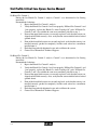
The Stat Profile CCX Analyzer is 2 instruments placed into one chassis. The right side contains
the sensors and assemblies used for the measurement of the Blood Gas (pH, PO2, PCO2),
electrolyte (Na+, K+, Cl-, iCa, iMg), and Metabolite (Glucose, Urea, Lactate, Creatinine)
analytes.
The left side of the instrument contains the assemblies needed to determine the CO-Oximeter
(tHb, O2Hb, COHb, HHB, Met HB, SO2%) measurements.
2-1
Stat Profile Critical Care Xpress Service Manual
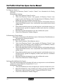
2.1
Mechanical Assemblies
4b
1a
9b
12
11
1b
9a
10
2
3
8
4a
5b
5a
6c
6a
7
6b
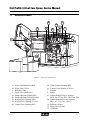
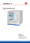
Figure 2.1 Analytical Compartment
1a.
1b.
2.
3.
4a.
4b.
5a.
5b.
6a.
2-2
Waste Line Blood Gas (BG)
Waste Line CO-Ox
Reference Line
Pinch Valve (Reference)
Pump and Pump Tubing (BG)
Pump and Pump Tubing (CO-Ox)
Reagent Pack Opening (BG)
Reagent Pack Opening (CO-Ox)
Control Pack Opening (BG)
6b.
6c.
7.
8.
9a.
9b.
10.
11.
12.
Chem Control Opening (BG)
Control Pack Opening (CO-Ox)
Sampler
Printer
Sensor Module Flow-by Sensors:
BUN, Lac, PCO2, SO2, Glu, Creat, PO2
Sensor Module Flow-thru Sensors:
Mg++, K+, Ca++, Na+, pH, ClReference Sensor
Pinch Valve (Waste)
CD ROM
2 Product Description
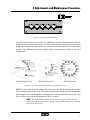
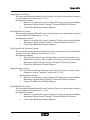
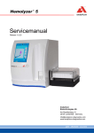
There are 2 separate fluidic systems joined by one common valve (splitter valve). On units
without the CO-Oximeter option, the splitter valve is not present. In its place, there is an S-Line
with 2 Air detectors.
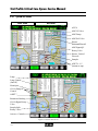
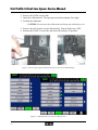
Figure 2.2 The System Test Diagram Screen
CO-Ox Rotary Valve
Splitter Valve
ABG Rotary Valve
Figure 2.3 The CO-Ox Reagent, Blood Splitter, and ABG Fluid Valves
The analyzer is designed to calibrate using internal Reagent packs. The exceptions being the
CO-Ox calibration and the SO2% and Hb channels on the ABG side, which require external
calibration standards.
2-3
Stat Profile Critical Care Xpress Service Manual
2.1.1 CO-Oximeter
The CO-Ox side of the CCX is comprised of 2 rotary valves, a blood detector, cuvette,
preheater assembly, and pump assembly.
The sample enters the CCX through the sample probe. The first segment of the sample passes
through a Blood Splitter Valve (PN 37850) and is positioned in front of the Blood Gas/
Electrolyte/ Metabolite sensors. The Blood Splitter valve then rotates aligning the sample path
with the CO-Oximeter side of the analyzer. The CO-Oximeter fluid pump aspirates the sample
through a T fitting where a lysing agent is added (6:1 ratio sample to lyse). The sample then
passes through an optical detector, a hemolyzer (PN 38155), a sample preheater (PN 36465),
and then pauses in the optical cuvette (PN 38167). A white light is passed through the sample.
The light escaping absorption is transported to a spectrophotometer via a light pipe. The sample
is the aspirated through the CO-Oximeter pump to the waste. The Blood Splitter valve rotates
to the flush position to clean the flowpath behind the sample. The flowpath between the sample
probe and the Blood Splitter valve is flushed by the blood gas flush solution.
The cuvette is washed at the end of the sample cycle. The splitter valve assembly rotates to the
CO-Ox rotary valve position. The CO-Ox Rotary Valve (PN 37849) has 5 positions. One
position is to the CO-Ox flush solution that cleans the system.
2.1.2 ABG (Electrolyte, Metabolite, Blood Gas)
The ABG sample enters the analyzer through the sample probe. If the analyzer does not have
a CO-Oximeter option, the sample passes through 2 air detectors on its way to a sample
preheater. If the analyzer does have a CO-Oximeter option, the sample is aspirated through one
in-line air detector. The second air detector is part of the blood splitter valve. The home position
of this valve aligns the sample probe with the ABG sample preheater. There are 3 heaters on
the ABG side of the unit: one is bolted to the bottom of the sensor module; one is in the sample
path for the PO2, PCO2 sensors; and one is in the flow through sensor section for the pH
measurement.
There are 6 air detectors: 2 on the S-Line (if the splitter valve is present, the S-Line has one and
the valve the other), 2 ADTs in the flow cell (ADT3 is used for the Hct measurement); and a
fifth ADT in the reference electrode.
Flow control on the ABG side is done with one pump, and 2 solenoid valves. The Waste
solenoid is normally open, and the Reference is a normally closed solenoid valve.
2-4
2 Product Description
2.2
Electronic Assemblies
2.2.1 Power Distribution
The analyzer connects to wall power via an Input Module. The main fuses are located on the
rear panel, left side (looking from the front of the instrument) directly above the power cord
inlet. The access door rotates downward exposing the 2 fuses. The fuse rating is 4.0 Amp for
100/120 Vac and for 220/240 Vac operation.
The Line Voltage Input module feeds the universal switching power supply. The secondary
outputs of the Power supply assembly are distributed either directly for the Analog and Control
Boards or to a Distribution Board, located on the left side of the analyzer.
2.2.2 Spare Parts - Description/Part Number
ABG Digital Control Board ............................................................................... 37449
Analog Board (2 per Unit – identical) ............................................................... 33390
Analog Board – CO-Ox ..................................................................................... 38165
Bar Code Reader ................................................................................................ 37624
Blood Detector ................................................................................................... 38159
CD ROM Drive ................................................................................................. 37451
Computer Board - ABG ..................................................................................... 36931
Computer Board - ABG with adapter board/power cable ............................... 40310*
Computer Board - CO-Ox ................................................................................. 38163
Control Assembly – CO-Ox (Digital Control Bd/CPU/Analog ........................ 37817
Cuvette Housing ................................................................................................ 38167
Cuvette Slide Assembly .................................................................................... 38042
Cuvette Window Kit .......................................................................................... 38179
Digital Board - CO-Ox ...................................................................................... 38157
Digital Board- ABG .......................................................................................... 37449
Display Door Assembly .................................................................................... 37084
Fan Assembly .................................................................................................... 37087
Flowcell Interface Board ................................................................................... 37103
Fluid Fountain/Spike ......................................................................................... 20861
Hard Drive ......................................................................................................... 37102
Hard Drive Assembly ........................................................................................ 40822
Hemolyzer ......................................................................................................... 38155
I/O Plate Connector ........................................................................................... 34932
Internal Keyboard .............................................................................................. 37478
2-5
Stat Profile Critical Care Xpress Service Manual
Inverter Board (Display) .................................................................................... 39505
Inverter Board (Display) .................................................................................... 39506
Keyboard Overlay – English ............................................................................. 37657
Lamp Assembly – CO-Ox ................................................................................. 37815
Optics Board ...................................................................................................... 38161
Power Distribution Board .................................................................................. 37101
Power Entry Module .......................................................................................... 37105
Power Supply ..................................................................................................... 37104
Preheater Assembly ........................................................................................... 36465
Printer Assembly ............................................................................................... 37138
Printer Head ....................................................................................................... 37484
Printer Interface Board ...................................................................................... 37485
Pump Assembly – ABG .................................................................................... 37092
Pump Assembly – CO-Ox ................................................................................. 38181
Reference Pinch Valve ...................................................................................... 37089
Rotary Valve – ABG ......................................................................................... 37091
Rotary Valve – CO-Ox ...................................................................................... 37849
Rotary Valve – Splitter ...................................................................................... 37850
Sampler Assembly ............................................................................................. 37083
Sensor Module/Flowcell .................................................................................... 36463
Speaker Assembly ............................................................................................. 37085
Spectrophotometer Board .................................................................................. 29401
Touch Screen Driver Board ............................................................................... 37452
Touchscreen Display ......................................................................................... 37448
Waste Pinch Valve............................................................................................. 37090
* CCX Analyzers built after June 30, 2005, use these Part Number replacements.
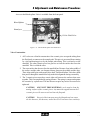
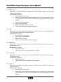
2.2.3 ABG Digital Control Board
Location:
The ABG Digital Control Board is located along the right side of the chassis, looking from the
front and is accessed from the right side of the analyzer. The CO-Ox Board Cluster is attached
to it.
Main Function(s):
Control of all the mechanical devices on ABG unit
- Sampler Assembly
- W/R Pump
- W/R Solenoid Valves
2-6
2 Product Description
-
ABG Reagent Rotary Valve
Controls ABG-RMS (Reagent Blood Gas and Chemistry QC).
Manipulates the digitized analog signals from the 2 Analog boards.
Power Connections to Board:
Power is delivered to the ABG Digital control board via the J7 Connector/Cable:
Pin 2: +24 VDC
Pin 6: +12 VDC
Pin 5: +5 VDC (VCC)
Pin 8: –12 VDC
J3: CPU Board
J13: Analog Board
J17: RMS
J14: Waste Valve
J16: ABG Pump (+24 VDC power)
J15: Reference Valve
J19: Sampler (+24 VDC power)
J29: Probe
J10: ABG Rotary Valve (+24 VDC power)
LED’s: (6 LED indicators on the board):
D7: “Program Load”: Bright during program load; then remains dimly lit.
D8: “Processor On”: Clock processor; brightly lit relating to clock speed.
D9: “Drivers”: On for loading of ‘mechanical devices program’ and then OFF.
NOTE: When D9 goes out, the 24 VDC is enabled to the ABG mechanical
devices. Each device moves to its Home position.
D22: “Heater 1”: ON when Heater 1 is turned ON (sensor module).
D23: “Heater 2”: ON when Heater 2 is turned ON (preheater).
NOTE: The preheater is turned ON/OFF in a timed cycle independent of
temperature.
D24: “Heater 3”: ON when Heater 3 is turned ON (pH).
Main Chips Information:
There are no serviceable/replaceable components on this board.
U3/U4 - Pump Control
U25 - Clock
Q3 - Heater Driver
U46/47 - Probe Motor
U29 - CPU
Q4/Q6 - Valve Driver
U5/U6 - Sampler Motor
U51 - Temperature Control
U20 - COM 2
U2/U7 - Rotary Valve
U30 - COM 3
U32 - Power Reset
U12 - Motor Control, I/O Multiplexer
2-7
Stat Profile Critical Care Xpress Service Manual
2.2.4 CO-Ox Digital Control Board/CPU/Analog Board
CO-Ox Digital Control Board:
Location:
The CO-Ox Digital Control Board is located along the right side of the chassis, looking from
the front. It is attached to ABG Digital Control Board. The CO-Ox CPU and Analog boards
are attached and electronically connected to the CO-Ox Digital Control Board.
Main Function(s):
Controls/powers the mechanical and electronic assemblies of the CO-Ox module:
CO-Ox Pump
CO-Ox Reagent Rotary Valve
CO-Ox ADET
Sample Split Rotary Valve
Hemolyzer
CO-Ox Cuvette (Preheater)
Controls CO-Ox-RMS (Reagent and CO-Ox QC monitoring).
Control, monitor and powers the Spectrophotometer.
Manipulates the digitized analog signal from the CO-Ox Analog board.
Power Connections to Board:
Power is delivered to the CO-Ox Digital control board via J29 Connector/Cable:
Pin 2: +24 VDC
Pin 5: +5 VDC
Pin 6: +12 VDC
Pin 8: –12 VDC
Connectors:
J19: CO-Ox Pump (+24 VDC power)
J20: CO-Ox Reagent Rotary Valve
(+24 VDC power)
J21: Sample Split Rotary Valve
(+24 VDC power)
J22: Hemolyzer (+24 VDC power)
J23: Ambient thermistor (Cuvette)
J24: Cuvette Housing: Blood Detector
2-8
J25: Lamp Adjust (Spectrophotometer)
J26: RMS/CMS (CO-Ox Reagent & QC)
J29: Power IN
J30: Lamp Voltage Feedback
J33: Lamp/Fan Power (6.25 VDC Lamp;
+12 VDC Fan power)
J36: Reagent Preheater (+24 VDC power)
2 Product Description
CO-Ox Analog Board:
Location:
The CO-Ox Analog Board is located along the right side of the chassis, looking from the front.
It is mounted to the CO-Ox Digital Control Board that is directly below the CO-Ox CPU Board.
Main Function(s):
Transmitted Light from the Cuvette (sample) is measured at 7 wavelengths. The 7 wavelength
signals are digitized on the Analog Board, and the result/signal is processed on the CO-Ox
CPU.
Connectors:
NOTE: Power to Analog Board is the same as for CO-Ox Digital Board as
all power and signals come from direct connection to CO-Ox Digital
Board.
J1: S2000 Spectrophotometer (special cable)
CO-Ox CPU Board:
Location:
The CO-Ox CPU Board is located along the right side of the chassis, looking from the front.
It is mounted directly to CO-Ox Digital Control Board that is above the CO-Ox Analog Board.
Main Function(s):
Communicates with Hard Drive for data acquisition and storage
Does all calculations and algorithms for CO-Ox module
Process digitized signal from CO-Ox Analog Board
Houses main CO-Ox Pentium Processor
Minimum: Celeron PC 366 MHz
2-9
Stat Profile Critical Care Xpress Service Manual
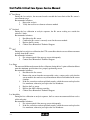
2.2.5 ABG CPU Board
Location/Information:
The ABG CPU Board is located along top left section of analyzer laying flat side up.
There are multiple source manufacturers possible. The current board is the PCM-6890B FC/
Socket 370 Celeron (Pentium) single board computer with LCD, Ethernet, Audio, and 4 COMs
(Min. Processor Speed = MHz; Min. Pentium Rating = Pentium III).
Main Function(s):
Controls basic analyzer's functions/devices:
CD-R Drive Keyboard/Mouse
Display
Audio
Keyboard/Mouse
I/O ports
Celeron Main CPU Processor, Calculations
Output Devices/Ports:
Ethernet
Serial/Comm
PCMCIA Card
USB
Houses Ports Directly on Board:
Serial/Comm
Ethernet
USB
PCM-6890B
Power Connections to Board:
The Power Supply connects via the CN9 connector. The Voltages are shown below:
Pins 4,6,19,20: +5 VDC
Pin 10:
+12 VDC
Pin 12:
-12 VDC
Pin 18:
-5 VDC
2-10
2 Product Description
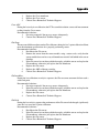
2.2.6 ABG Analog Boards
Location/Information:
NOTE: Two identical boards used on system; same part #’ s.
The ABG Analog Boards are located at middle of analyzer directly behind the flowcell area.
The boards are mounted vertically to the chassis and are connected by cables to the sensor
module (flowcell Interconnect). The boards are identical except for jumper changes.
Board # 1= Right (from front)
Board # 2= Left (from front)
NOTE: The CCX (Basic) uses only Analog Board #1.
Main Function(s):
The CCX utilizes 2 identical Analog Boards. This board is also used on the pHOx Plus and
pHOx Plus L models. The board receives the sensor output and performs the A/D conversion.
The digitized signal is then passed to the ABG digital control board for processing. The
replacement board will require setting 6 jumpers to the correct positions based on use. See chart
below.
Analog Board Jumper positions
Jumper
Jumper
JPR 1
JPR 2
JPR 3
JPR 4
JPR 5
JPR 6
o———-o
1
2
pHOx+/+L
3 to 4
3 to 4
3 to 4
3 to 4
3 to 4
3 to 4
or
o———o
3
4
CCX Basic
1 to 2
1 to 2
1 to 2
3 to 4
3 to 4
3 to 4
CCX Board 1 CCX Board 2
3 to 4
3 to 4
3 to 4
1 to 2
3 to 4
1 to 2
3 to 4
1 to 2
1 to 2
3 to 4
1 to 2
3 to 4
2-11
Stat Profile Critical Care Xpress Service Manual
The individual analyte board and channel assignments are as follows.
Analyte Board 1
Calcium
Potassium
Sodium
pH
Chloride
PCO2
Barometric Pressure
Creatinine
Lactate
Glucose
SO2 (LED1)
SO2 (LED2)
ADT 5 (Flowcell)
ADT 4 (Flowcell)
ADT2 (S-line)
Reference
Channel
1
2
3
4
5
6
7
13
14
15
21
22
32
33
36
23
Analyte Board 2
BUN
Magnesium
PO2
ADT 6 (Ref)
ADT 3 (Preheater)
ADT 1 (S-line)
Reference
Channel
41
45
54
72
73
76
23,63
2.2.7 Flowcell Interface Board
The Flowcell Interface Board connects the sensor module with the appropriate Analog Board.
Location/Information:
The Flowcell Interface Board is directly behind flowcell/sensor module and connects to the
flowcell.
Main Function(s):
It connects the flowcell (sensor inputs) to the Analog Boards. There are no active components,
test points, or LED’s on this board.
2-12
2 Product Description
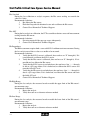
2.2.8 Power Distribution Board
Location/Information:
The Power Distribution Board is mounted to the left side of the analyzer looking from the front.
Main Function(s):
The Power Distribution Board receives input voltages from power supply assembly and
distributes the regulated voltages to the instrument circuit boards. Each line is protected by a
thermal fusister (self-resetting). The voltage for each board may be detected by placing a probe
on the metal top of the fusister (FB), as this is the output to the peripheral boards.
Power Connections to/from Board (Connections for Peripheral Devices):
J 2 PIN 1: Power Fail, PIN 2: Ground
J 3 (to ABG Digital Control Board):
PIN
Voltage
2
+24 VDC
4
+5 VDC
6
+12 VDC
8
-12 VDC
Test Points
FB11 Plus Leg C 4
FB 5 Plus Leg C27
FB 6
RT3
FB 3
RT4
J 4 (to Seiko Printer Assembly; Power)
PIN
1 +5 VDC
5/6 +24 VDC
Test Points
FB 8 Plus Leg C19)
FB 7 Plus Leg C7/8/9)
J 5 (Printer {Signal} Interface):
PIN Number Signal
PIN Number
Signal
1
Ground
11
ACK/
2
STROBE/
12
BUSY
3
DO
13 & 22
+ 5 VDC
4
D1
( Test at + leg C19, JPR3 installed)
5
D2
14
PE
6
D3
15
ERR/
7
D4
16
STO
8
D5
17
NC
9
D6
18
ST2 (JPR6 jumper it to J6 – 25)
10
D7
19
INIT/
2-13
Stat Profile Critical Care Xpress Service Manual
J 6 (‘Computer {Signal}LPT’):
PIN Number Signal
1
STROBE/
2
AFD/
3
D O/
4
ERR/
5
D1
6
INIT/
7
D2
8
SEL_IN TP1
10/12/14/16/18/20/22/24/26:
J 7 (to CPU Board):
PIN
4
10
12
18
PIN No
9
11
13
15
17
19
21
23
GROUND
Voltage
+5 VDC
+12 VDC
-12 VDC
-5 VDC
J 8 (to Hard Drive):
PIN
Voltage
1
+12 VDC
4
+ 5 VDC
J9 (to LCD Back-Light):
PIN
Voltage
1-3
+12 VDC
5,7,9
Ground
J10 (to Touch Screen):
PIN
Voltage
1
Ground
2
+12 VDC
J11 (to CO-Ox Digital Control Board):
PIN
Voltage
2
+24 VDC
4
+5 VDC
6
+12 VDC
8
-12 VDC
2-14
Signal
D3
D4
D5
D6
D7
ACK/
BUSY
PE
Test Points
Plus Leg C16
Plus Leg C14
Minus Leg C13
Minus Leg C15
Test Points
JPR 9, Plus Leg C26
JPR 10, Plus Leg C20
Test Points
FB 4, Plus Leg C12
Test Points
JPR 5
Test Points
FB 10, Plus leg C2
FB 9, Plus Leg C5
Resistor RT1
Resistor RT2
2 Product Description
J16 (‘Audio-In) Pin 1, Ground Pin 2
J17 (‘Audio-Out) Pin 1, Ground Pin 2
Printer Status LED’ s:
D2: ST1
D4 ST2
D3 ST0
D5 ERR/
D6 PE
2.2.9 Power Supply Assembly
Location/Information:
Located at rear base of analyzer near power line input.
Main Function(s):
The Universal Power Supply is 100-240 VAC, 50/60 Hz, and Medical-grade. The UniversalSwitching Power Supply accepts 92 – 232 VAC, converts AC voltages to DC voltages, and
supplies secondary voltages to the Power Distribution Board.
Power Connections from Assembly (to Power Distribution Board):
J1 Ground-Neutral
J2 (to Power Distribution Board):
J2 On Distribution Bd.
PIN
Voltage
1
Ground/Power Fault
2
-12 VDC
3
+12 VDC
4-9
Voltage return lines
10-13
-24 VDC
14-17
+5 VDC
LED’s: (None)
J 1 On Distribution Bd
Test Points
Pins 1
2
3
4-9
10-13
14 - 17
2.2.10 Power Entry Module
Location/Information:
The Power Entry Module is located at rear base (wall) of analyzer.
Main Function(s):
It accepts wall (AC) power.
2-15
Stat Profile Critical Care Xpress Service Manual
2.2.11 Hard Disk Drive
Location/Information:
The Hard Disk Drive is located on the central left side (from front) of CCX chassis.
Main Function(s):
It stores the analyzer's program as well as analysis, data, and QC, and can read/write
information from/to the R/W CD-ROM drive.
Minimum 20 GB drive
Operating Voltage: + 5 VDC
2.2.12 R/W CD-ROM Drive
Location/Information:
The R/W CD-ROM Drive is located at the upper left side (from front) of CCX chassis and is
lying horizontally.
Main Function(s):
It is a standard computer Read/Write (R/W) CD-ROM Drive 16x (minimum).
The computer drive can be replaced only with a Windows 200 compatible drive.
Reads standard CD-ROM’s and also writes to blank CD’s information from Hard Drive
Provides long-term backup data and information storage for system. Operating Voltage: + 5
VDC
2-16
3 Replacement Procedures
3
Replacement Procedures
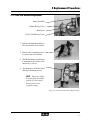
3.1
Cover Removal
CAUTION:
Assemblies may have loose hardware mounting. Ensure no
loose hardware is left in the unit before restoring power to the analyzer.
!
WARNING:
Removal of the analyzer cover exposes the line voltage
wiring. The Power must be turned off and the Power Cord disconnected
before any assembly replacement procedure is performed.
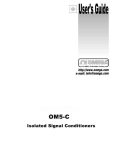
1.
2.
3.
4.
Turn the unit OFF, disconnect the line cord, and have the back of the unit facing you.
Remove the 8 panel mounting screws.
Slightly spread the bottom sides and lift the cover upward and toward the back.
Lift the cover off the unit. Take care not to damage any cables or wiring during
removal.
Figure 3.1 Cover Mounting Screw Location
3-1
Stat Profile Critical Care Xpress Service Manual
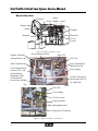
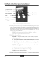
Major Assembly Location
CD Drive
Sensor
CO-Ox Module Pump
Display
Printer
Sampler
Reagents
Hemolyzer
CO-Ox
Cuvette
Figure 3.2 Major Assemblies, Front
Sampler Assembly
Sensor Interface Board
Host CPU
Analog Boards 1 & 2
CPU Fan
ABG Control Board
Power Distribution
Mounted on side
CO-Ox Board Stack
(Control, CPU, and
Analog Board)
Mounted to ABG
Control Board
Power Entry Module
Power Supply
Analyzer Fan (Space
on rear panel for COOx Light Fan)
Top
Back
Host CPU
CO-Ox Pump
CO-Ox Cuvette
Lamp Assembly
Spectrophotometer
Lamp Power Transistor
Figure 3.3 Major Assemblies - CO-Ox Areas
3-2
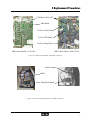
3 Replacement Procedures
COM Port to Host CPU
ABG Board
CO-Ox Control Board
CO-Ox CPU Board
CO-Ox Analog Board
ABG Control Board - No CO-Ox
ABG Control Board - With CO-Ox
Figure 3.4 ABG Control Boards - Right Side of Analyzer
Cable to Display
Shield
Power Distribution Board
Figure 3.5 Power Distribution Board - Left Side of Analyzer
3-3
Stat Profile Critical Care Xpress Service Manual
Sampler
Fan
ABG Board
ABG Tubing
Individual
Tubes
ABG QC Tubing
ABG Rotary
Valve
CO-Ox
Reagent
Preheater
I/O Port
Line Input
USB Port
Figure 3.6 Rear Panel
ABG Fluid Pack
Compartment
CO-Ox QC
Compartment
CO-Ox Fluid Pack
Compartment
Metabolite QC
Pack
Compartment
Keyboard
Mouse
Connectors
ABG QC Pack
Compartment
Keyboard
(Not shown)
Figure 3.7 Front Panel (Bottom)
3-4
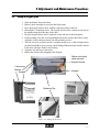
3 Replacement Procedures
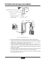
3.2
Sensor Module
WARNING:
The Power must be turned off and the Power Cord disconnected before changing the Sensor Module.
1. Remove the S-line from the preheater.
2. Disconnect the W and R tubing from the reference electrode.
3. The sensor module is held in place by 2 locking tabs. Turn the thumb screw fully
counterclockwise. Then pull the sensor module towards you.
NOTE: If reinstalling the sensor module after changing the sensor module
Interface Board, leave the Interface Board mounting screws loose until the
sensor module is in place. This ensures proper alignment of the connectors.
Sensor Module
Mount Thumb Screws
Preheater
Holes for the
Mounting Tabs
Figure 3.8 Sensor Module
4. Reinstall the sensor module –
- Ensure the locking tabs are in the same alignment as the holes on the fluid
panel.
- Set the module in place; apply a slight pressure to the bottom of the
assembly to ensure a good connection between the module and the Interface
Board.
- If required, tighten the Interface board mounts.
- Reconnect the W/R and S-line tubing.
3-5
Stat Profile Critical Care Xpress Service Manual
3.3
Preheater
1. Remove the Sensor Module from the fluid panel.
2. Invert the Sensor Module.
3. The preheater is mounted by 2 screws.
NOTE: Be careful removing or installing the mounting screws. The ground
wire can be easily cut or damaged.
4. Install the new preheater by reversing these steps.
Ground Strap
Mount Screws
Preheater
Figure 3.9 Preheater
3.4
Sensor Module Interface Board
The Interface Board is mounted inside and behind the sensor module.
1. Remove the analyzer cover and the sensor module.
2. Disconnect the cables from the Interface Board.
NOTE: The Analog Boards are only different due to jumper positioning.
Verify that you matched the labels where each cable is connected.
3. Install the Interface Board leaving the mounting screws loose enough to allow some
movement.
4. Mount the sensor module to align the Interface Board with the Sensor Module.
5. Tighten the interface mounting screws.
Interface Board
Interface Board
Mounting Screws
Analog Boards 1 and 2
Figure 3.10 Sensor Module Interface Board
3-6
3 Replacement Procedures
3.5
Analog Boards
1. Remove the analyzer cover.
2. The Analog Boards are slid into the card holder with no mounting hardware.
Disconnect the cables and slide the board upward.
3. Verify that the jumper settings are correct before installing the new board.
Jumper
Jumper pHOx+/+L
JPR 1 3 to 4
JPR 2 3 to 4
JPR 3 3 to 4
JPR 4 3 to 4
JPR 5 3 to 4
JPR 6 3 to 4
o————o o———o
1
2 3
4
CCX Basic CCX Bd 1 CCX Bd 2
1 to 2
3 to 4
3 to 4
1 to 2
3 to 4
1 to 2
1 to 2
3 to 4
1 to 2
3 to 4
3 to 4
1 to 2
3 to 4
1 to 2
3 to 4
3 to 4
1 to 2
3 to 4
Analog Board 2
Analog Board 1
Figure 3.11 Analog Boards 1 and 2
3-7
Stat Profile Critical Care Xpress Service Manual
3.6
ABG Computer Board (CPU)
NOTE: The CPU PN 40310 requires the PN 40822 Hard drive.
The CPU PN 36931 requires the PN 37102 Hard drive.
NOTE: Units manufactured after June 30, 2005, will have an adapter board
mounted above the CPU.
NOTE: If installing a CPU with Adapter board into a unit manufactured
before July 1, 2005, DO NOT connect 2-wire Audio cable from CN13 to CN1.
1.
2.
3.
4.
5.
6.
7.
Remove the analyzer cover.
Remove the ground wire from the shield plate.
Remove the 3 mounting screws. Then remove the shield.
Disconnect the cable connectors.
Remove the CPU fan.
Remove the mounting screws.
Install the board by reversing the steps above.
Adapter Cable
CPU (PN37579)
Adapter Board (PN38900)
Complete Set PN40310
Power Supply Assembly
FAN CLIP push and
release on rear side.
Manufactured before July 1, 2005
Manufactured after June 30, 2005
Figure 3.12 Host CPU
3.7
ABG CPU, CD Drive, and Hard Drive Assemblies
!
CAUTION: The CPU card does not have a protective coating to ensure
all screws, washers, or other metal pieces do NOT touch any part of the
circuitry while power is on to the analyzer.
1. Turn the analyzer off and remove the power cord.
3-8
3 Replacement Procedures
2. Remove the analyzer's cover.
NOTE: On analyzers manufactured after June 30, 2005, Access to the rear
cabling is made easier by removing the speaker assembly from the fan.
Speaker removal procedure:
a. The speaker is mounted to the top 2 fan mounting screws.
b. The speaker is plugged into the Distribution Board J17. It will be easier to
lay the speaker to the side. If removed, verify that the cable lays along the
same path as it did before being removed.
Speaker Mount
Screws
Cable Dressing
J17
Figure 3.13 Speaker Removal
3. Remove the ground wire from the shield plate.
4. Remove the 3 mounting screws. Then remove the shield.
5. Disconnect the connector from the CPU Board. Note how the cable is routed, i.e., the
sound wire is routed under the CPU.
6. Remove the ABG CPU Card.
7. If replacing this assembly, mount the replacement by reversing the above steps.
8. The CD and Hard Drives are mounted to one chassis bracket. The bracket is held to
the chassis by 2 screws on the side closest to the edge of the analyzer and one accessed
from the middle of the analyzer.
9. After removing these screws, the bracket and drives may be removed out the top of
the analyzer.
10. The individual drive is held to the bracket by screws on each side.
!
CAUTION: Pay strict attention to how the flat data cable and the display cable
(not keyed) are attached to each device. Severe damage may occur if not connected
correctly: in particular, the Drive Data (flat cable) Connector on the ABG CPU.
3-9
Stat Profile Critical Care Xpress Service Manual
NOTE: Red wire is to the Left looking from the rear of the analyzer.
NOTE: There are no guides. Ensure all the pins of the Board Connector
are inside the Cable Connector.
The Red Wire
Figure 3.14 The Red Wire is to the Left
11. Each drive has a power cable, flat data cable, and a jumper connector. Ensure the Red
Wire of the Data Cable is on the right side when connected as seen from the rear of
the analyzer.
Red Wire on Left
ABG CPU Board
CD Drive
Hard Drive
Red Wire on Right
Figure 3.15 The Drives
12. The CD Drive and Hard Drive have
jumpers to direct their address signals
from the CPU. Ensure the replacement
Drive Jumper is in the same place as
the one being replaced.
13. Reverse Steps 1-10 to reinstall the
Disks Drives and ABG CPU
14. Restore the analyzer to normal operation.
Figure 3.16 Jumper Middle Pins
3-10
3 Replacement Procedures
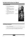
3.8
Power Supply Assembly
1. Remove the analyzer cover.
2. The power supply is mounted to the chassis behind the CPU. The mounting screws
are located on the chassis above (to the left) and one behind the Power Distribution
Board.
3. Disconnect the connectors, remove the mounting screws, and lift the assembly out
the top of the unit.
4. Reverse the steps to install the Power Supply.
3.9
Power Distribution Board
1. Remove the analyzer cover.
2. Disconnect the cables.
3. Remove the mounting
screws, freeing the board.
4. Reverse the steps to mount
the new board.
Mounting
Screws
Figure 3.17 Mounting Screws
3-11
Stat Profile Critical Care Xpress Service Manual
3.10 Fluid Pack RMS Cables
1. Remove the analyzer cover.
2. Each fluid pack RMS cable is mounted by a bracket attached with screws to the
fluidic compartment.
RMS Cable Harnesses
Figure 3.18 RMS Cable Harnesses
3.11 Sampler Assembly
1. Remove the analyzer cover.
2. Remove the tubing from the Sampler Assembly. Remove the sample probe. Remove
the cover plate located at the bottom, front of the Sampler Assembly to allow access
to the C-line/Fluid Fountain connection (2 hex key screws).
3-12
3 Replacement Procedures
3. Unplug the sampler motors from the ABG Controller Board.
4. The sampler is mounted by 2 screws at the front of the assembly and 2 screws at the
rear of the assembly.
5. The rear inside mount is slotted. The hex key screw are only loosened.
6. After removing the other 3 screws, slide the assembly forward and lift it from the
chassis.
7. Install the assembly by reversing Steps 2 through 5.
Front
Rear
Hex
Screws
Slotted Hex Screw Mount
Figure 3.19 Sampler Assembly
3.12 Capillary Adapter Light
1.
2.
3.
4.
Shutdown the analyzer and remove the Sample Probe.
Remove the Sampler Assembly.
Rotate the gears manually to raise the probe to the capillary position.
Remove the 2 shoulder screws and the slide guide from the sampler.
NOTE: There is a spring between the Capillary Adapter and the body of the
Sampler Assembly.
5. Align the Illuminated Capillary Adapter Mount such that the Capillary Adapter
mount is on the smooth side (labeled Front on the diagram below), and the spring
support is on the side having a raised section (labeled Back on the diagram below)
using the 2 crosshead screws.
3-13
Stat Profile Critical Care Xpress Service Manual
Slide PN34896 (smooth side up)
Shoulder Screws PN34910
Spring PN35738
Illuminated Capillary
Block PN38566
Back
Slide Guide
Front
Crosshead Screws
Spring
Figure 3.20 Capillary Adapter Light
6. Insert the spring into the recess on the back of the Capillary Adapter mount.
7. Mount the new Slide Guide with illuminated adapter onto the sampler, using the 2
shoulder screws. Rotate the wheel on the top of the sampler to lower the sample
needle holder to a mid position to make this step easier.
8. Snugly Tie-wrap the illuminated capillary adapter cable to the tie-wrap anchor. Tiewrap the motor cables to the illuminated capillary adapter cable such that they run
together. The tie-wraps along the 2 sampler mount cables should be loose enough to
allow some movement.
9. Reinstall the sampler and connect the illuminator cable into the ABG control board
J8, which is located at the bottom left corner of the ABG control board.
11. Exercise the sampler to assure the cable move freely, without crimping or rubbing,
then reinstall the instrument cover.
3-14
3 Replacement Procedures
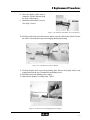
3.13 Sampler Assembly Motors
1. Remove the sampler assembly.
2. The probe motor is mounted to the top plate. Remove the top
plate mounting screws that are located on the side of the
plate.
3. Lift the motor and lead screw from the assembly.
4. The motor is attached to the lead screw by set screws and to
the top plate by 2 mounting screws at the top.
5. The tilt motor requires the mechanism to be tilted by hand
to expose the 4 mounting screws. The motor and worm gear
are one assembly.
6. Reverse Steps 2 through 5 to install the new motors.
Figure 3.21 Sampler Assembly Motors
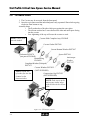
3.14 ABG Pump Assembly
1.
2.
3.
4.
Remove all tubing from the pump assembly. Remove the analyzer cover.
Remove the 4 mounting screws for the solenoid and pump assembly.
Detach the 3 electrical connectors.
The solenoid valve are snapped in place from the rear, each with an electrical
connector. Unplug the valve from the ABG Control Board. Move the clip toward the
outside of the unit. Push the valve from the front of the unit.
5. The pump assembly is held in by 3 mounting screws and the pivot point thumb screw
of the tension arm.
6. Remove the tension arm and mount screws, hold the motor from the rear.
7. Install the new pump assembly by reversing the above steps.
4 Mounting Screws
to Remove Pump
and Solenoid
4 Mounting Screws
for Pump Motor
1 Under Bracket
Rear
Figure 3.22 ABG Pump Assembly
3-15
Stat Profile Critical Care Xpress Service Manual
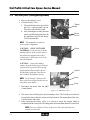
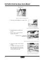
3.15 ABG Rotary Valve (Cleaning and Replacement)
1. Remove the analyzer cover.
2. Clean the Rotary Valve.
a. The manifold and rotor are held in
place by a spring loaded cap nut.
The nut is removable by hand.
b. After cleaning the ceramic rotor and
stator, wipe the mating surfaces with
the applicator found in the Rotary
Valve Lubricant Kit.
Thumb
Nut
Mount
Screws
NOTE: The manifold is notched to
ensure proper alignment.
CAUTION: ONLY LINT FREE
MATERIAL is to be used to clean the
mating surfaces of the ceramic pieces.
Any material trapped between the 2
ceramic pieces will cause an air leak
into the flowpath.
Mount
CAUTION: Inspect the mating
surface of each ceramic piece to ensure
no pool of oil is present. Oil entering
the flowpath will desensitize the Air /
Hct detectors, and may Coat the surfaces of the CO-Oximeter cuvette.
Optical
Stator
NOTE: Verify that the 2 holes on the
back of the rotor align with the pins on
the pinion of the motor.
Rotor
3. Disconnect the motor from the ABG
Control Board.
Figure 3.23 ABG Rotary Valve
4. The rotary valve is held in place by 4 mounting screws. The 2 inside screws that are
located at the slots in the base only need to be loosened. The mount plate of the valve
is slotted on the inner side.
5. When replacing the Rotary Valve, it is critical to ensure the reagent tubing is
reconnected to the correct port. The tubing starts at lower bottom and moves clockwise.
NOTE: There are 3 Rotary Valves on this unit. The stator and rotor are
unique to each valve.
3-16
3 Replacement Procedures
3.16 Printer Assembly/ Printer Board
1. The Printer is mounted on the back of the
left side, front door by 2 thumb tab screws.
These screws must be turned fully
counterclockwise to align the tabs with
the mounting holes.
2. While removing the Printer, be careful
not to damage the wires coming from the
Power Distribution and Host Computer
Boards.
Mount
Screws
NOTE: To fit the Printer Cable
connector P4 through the front
panel, remove the connector cap
and dress the wire along the
grooves in the connector. See
Figure 3.24.
P4
3. Install the new assembly by reversing the
above steps.
P4 Cap
Figure 3.24 Printer Assembly Removal
3.17 Display Assembly
1. Remove the Printer Assembly to access the
mounting screws.
2. The Display is attached to
the door by 4 mount screws
Mount
Screws
CAUTION: Support
the heavy display
while removing the
last screw.
Figure 3.25 Removal 4 Mounting Screws
3-17
Stat Profile Critical Care Xpress Service Manual
Mount Screws
Figure 3.26 Removal 4 Mounting Screws
3. Disconnect the Backlight power supply cable.
Figure 3.27 Disconnect Backlight Cable
4. Unfold the display assembly from
the door.
5. Remove the 2 screws from the
display cable bracket.
2 Mount Screws
Figure 3.28 Removal 2 Screws from Cable Bracket
6. Unplug the display cable from the
display.
7. To install a new display or new display cable, the procedure is the same.
Place the display face down and connect the touch screen cable.
Figure 3.29 Display Cable Removed
3-18
3 Replacement Procedures
8. Inset the display cable onto its
connector. Let the cable run along
the back of the display.
9. Install the cable bracket 2 screws.
(See Step 5 above.)
Figure 3.30 Fold the Cable Back Across the Bracket
10. Fold the cable back across the bracket and tie wrap the cable to the bracket. Ensure
the cable is dressed flat to prevent cramping during remounting.
Figure 3.31 Tie Wrap the Cable to Bracket
11. Fold the display back across the mounting plate. Ensure the display cable is not
trapped between the two. Reinstall the mounting screws.
12. Reconnect the back lighting power supply.
13. Remount the display reversing Steps 1 and 2.
Figure 3.32 Reconnect the Backlighting Power Supply
3-19
Stat Profile Critical Care Xpress Service Manual
3.18 Door Alignment
1. The door alignment is done in 2 parts. Each hinge has an adjusting hex screw and lock
down screw on the side.
2. The hinge part attached to the door have a limited in/out adjustment possible.
3. The lower door may be adjusted after removing the black reagent pack retention bar.
4. When properly aligned, the following conditions must be verified:
a. The distance between the bottom door and the 2 upper doors will be
consistent at 1 - 2 mm (0.040 - 0.081 in).
b. The space between the 2 upper doors will be consistent.
c. The 2 upper doors will close, left side first, with no obstructions.
Right Hand Door
Left Side
Adjustment
Right Side
Lock Screw
Figure 3.33 Door Alignment
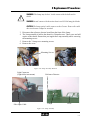
3.19 CO-Oximeter Assemblies
The major assemblies for the CO-Oximeter option are located in the middle of the analyzer.
The lamp assembly and spectrophotometer are mounted to the chassis. The pump, cuvette,
hemolyzer, blood splitter valve, CO-Ox fluid valve, and blood detector are mounted to the fluid
deck.
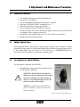
3.19.1 Lamp assembly
1. Remove the analyzer cover.
2. The lamp assembly is located at the rear and to the right when looking at the back of
the analyzer.
3-20
3 Replacement Procedures
!
WARNING: The Lamp may be hot! Avoid contact with the bulb and its
shield.
WARNING: Avoid contact with the main chassis and CO-Ox lamp fan blades.
CAUTION: The Lamp optical cable connects to the Cuvette. Ensure this cable
does not become crimped or strained.
3. Disconnect the reference detector board from the front of the Lamp.
4. The Lamp assembly is held to the chassis by 2 thumb screws. These screw are held
captive to the chassis. Ensure that you support the Lamp assembly while removing
the mounting screws.
5. Remove the 3 Lamp cover mounting screws.
6. Remove the cover.
Mounting Screws
Figure 3.34 Lamp Assembly Removal
Light Connector
(Light slides into mount)
Fiber Optic Cable
Reference Detector
Lamp
Cover
Figure 3.35 Lamp Assembly
3-21
Stat Profile Critical Care Xpress Service Manual
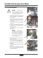
3.19.2 CO-Ox Fluid Deck Removal
!
CAUTION:
The Fiber optic
cable connecting the cuvette to
the spectrophotometer is a single
strand and easily damaged.
1. Open the front panel doors. Removal of
the Sensor Module is recommended before starting.
2. Remove the bottom door latch bracket.
This bracket is slotted thus only loosen
the 2 screws.
3. Loosen the fluid deck lower mounting
screws (2).
4. Loosen the internal fluid deck internal
mounting screw. Be careful as this is a
NOT captive nut.
5. Disconnect all motors and the
hemolyzer, etc.
CAUTION:
These cables
route passed the Analog Boards.
They MUST Be routed along the
same path when reinstalled, to
prevent electronic instabilities
on the analog boards.
6. Remove the 4 cuvette mounting screws,
one in each corner.
7. Pull the cuvette forward enough to allow access to the optical light pipes.
8. Loosen the hex screws, one on each
light pipe.
9. Slide the light pipe out of the back of the
assembly.
10. Remove the 2 fluid deck front panel
screws and slide the fluid deck out the
front of the analyzer.
Figure 3.36 Fluid Deck Removal
3-22
3 Replacement Procedures
3.19.3 Fluid Deck Mechanical Replacement.
Pump Assembly
Splitter Rotary Valve
Hemolyzer
CO-Ox Fluid Rotary Valve
1. Remove the fluid deck and lie it
face down on the work surface.
2. Remove the 3 mounting screws
to remove the valve bracket.
3. The Blood splitter valve bracket
is mounted to the CO-Ox valve
bracket by 3 screws.
4. The Hemolyzer is held to fluid
deck by 4 mounting screws.
NOTE: Ensure the cables
between these assemblies
and the CO-Ox control
board retrace their
original routing.
Figure 3.37 Mechanized Fluid Deck Replacements
3-23
Stat Profile Critical Care Xpress Service Manual
3.19.4 CO-Ox Pump Assembly
1. The CO-Ox pump optical detector
must be removed prior to removing the pump.
2. The optical detector is mounted to
analyzer chassis below the pump.
Remove the mounting screws at
the bracket.
3. The pump assembly is mounted
from the front panel. Remove the
corner hex key mounting screws.
4. Remove the pump out the rear of
the unit.
Figure 3.38 CO-Ox Pump Assembly
3.19.5 CO-Oximeter Electronic Boards
1. There are 3 individual electronic boards: the CPU and Analog Boards are socketed
to the CO-Ox Control Board.
2. The nested set of CO-Oximeter boards is mounted over the ABG Control board.
These are located on the right side of the analyzer looking from the front.
3. Review the wiring routing prior to disconnecting them from each board.
3-24
3 Replacement Procedures
3.20 Spectrophotometer Assembly
1. The spectrophotometer is mounted to the chassis by 3 screws that are accessed on the
rear of the analyzer.
2. The optical cable coming from the cuvette is held by a hex screw. Care should be
taken when removing the single strand cable. Any crimping or breakage will cause
a failure to calibrate.
Mounting Screws
Figure 3.39 Rear of Analyzer
Spectrophotometer
Figure 3.40 Spectrophotometer Assembly
3-25
Stat Profile Critical Care Xpress Service Manual
3.21 CO-Oximeter Cuvette
1. The Cuvette may be accessed from the front panel.
2. Once the cap is unscrewed the individual parts easily separated. Shown below going
clockwise from bottom to top,
Assembly hints:
• The D washer has a flat side which goes against the outer glass.
• The silicone washer has 2 cones that seal the inlet and outlet ports facing
into the cuvette.
• Over tightening of the cap will cause the cuvette to crack.
NOTE: Cones point
toward window.
Cuvette Slide Complete Assy. PN38042
Cuvette Gasket PN37909
Cuvette Bottom Window PN37897
Preheater PN38178
(not part of PN38042)
Bottom Ring
PN38058
Spacer PN37416
Compliant Washer (D-shaped)
PN37475
Cuvette Window PN37635
(NOT SUPPLIED)
NOTE: Round side
Compression Cap PN37633
of washer fits into the
(NOT SUPPLIED)
channel on the
bottom window.
NOTE: Tabs (ears) on the
anti-torque washer align
with the slots in the cuvette
slide.
Figure 3.41 CO-Oximeter Cuvette
3-26
Anti-torque
Washer
PN37157
3 Replacement Procedures
3.22 Replacing the SO2 Amp Board
It is feasible to change the SO2 Amp Board without affecting any other components inside of
the Sensor Module. It is important to note that none of the cables connected to any other
component should be moved.
Note: This procedure applies only to Sensor Modules with lot number
306671 or higher. Sensor Modules prior to this specified lot require replacement of the entire sensor module. All international warranty claims
must include Sensor Module lot number for approval.
PROCEDURE:
1. Perform a Purge Flowpath procedure on the maintenance menu.
2. Turn the analyzer off.
3. Remove the Sensor Module from the analyzer. Then remove the SO2 sensor.
4. Remove the back plate and disconnect the cable from the SO2 Amp Board.
5. Remove the rubber spacer behind the SO2 Amp Board.
6. Remove the defective board and replace with a new one (PN 38114 SO2 Amp Board).
7. Reinstall the rubber spacer.
8. Connect the cable and reinstall the SO2 sensor. (The sensor holds the board in place.)
9. Reinstall the back plate
10. Install the Sensor Module back onto the analyzer. Then reboot the analyzer.
11. After calibrating the SO2 and Hb channel, verify that the mv for LED 1 (Light) is
greater than 10 mv (only if replacing the SO2 board for an LED1 failure).
3-27
Stat Profile Critical Care Xpress Service Manual
3-28
4 Troubleshooting
4
Troubleshooting
This chapter assumes the reader is familiar with the operation of the CCX Analyzer and has
read the user manuals.
4.1
Limitations and Dependencies
Model Specific programming – The Hard Drive, ABG Digital Control Board, and Host CPU
are labeled by software to be model specific.
*
*
*
In the rare occasion that all three (Host CPU, ABG Digital Control Board, and Hard
Drive) require replacement, call NOVA Technical Service.
You may change only one of the above items at one time without restriction.
The newly installed assembly will assume the model specific labeling of the other 2
assemblies regardless of any previous programming.
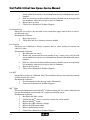
Analyte Dependencies
Analyte
BUN
Requirement
Na+ and K+ installed and calibrated
Default
Entered by user
Hb-ABG
Hct (requires Na) & SO2 reporting
14.5 g/dL
Hct
Na+ installed and Calibrated
iMg
iCa installed and calibrated
PCO2
pH calibrated
SO2%
Hct calibrated
Na+, Cl-, iCa,
iMg, BUN, pH
Reference Electrode
NOTE: Suppression of a channel will suppress any dependent channel.
4-1
Stat Profile Critical Care Xpress Service Manual
4.2
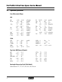
Operational Specifications
Linear (Measurement) Ranges
ABG
pH
PCO2
PO2
Na+
Ca++
Mg++
BUN
Creat
6.50
3.0
(0.4
0
(0.0
80
0.1
(0.4
0.1
3.0
0.2
-
8.00
200
26.7
800
106.7
200
5.0
10.8
2.5
100.0
20.0
pH units
mmHg
kPa)
mmHg
kPa)
mmol/L
mmol/L
mg/dL)
mmol/L
mg/dL
mg/dL
H+ 316.23 - 10.0
SO2 30
- 100
Hb
4
- 24.0
(2.5 - 14.9
Hct 12
- 70
+
K
1.0 - 20.0
Cl
50
- 200
Glu
5
- 500
(0.83 - 27.75
Lac
0.3 - 20.0
5.0
0
0
0
0.0
-
30.0
100
100
100
34.75
gm/dL
%
%
%
vol %
O2Hb
FO2Hb
MetHb
O2Ct
0
0
0
0.0
- 100
%
1.00
- 100
%
- 34.75 vol %
PCO2
Na+
K+
Ca++
Glu
Lac
Creat
7.9
8.8
8.3
8.3
5.0
6.0
3.0
- 12.6
- 11.0
- 12.1
- 12.6
- 45.0
- 100.0
- 25.0
nmol/L
%
g/d
mmol/L)
%
mmol/L
mmol/L
mg/dl
mmol/L)
mmol/L
CO-Ox
tHb
SO2%
COHb
HHb
O2Cap
Slope Limits (ABG Measured Channels)
pH
9.1 - 11.6
PO2
-15.0 - -1.6
9.5 - 15.0
Mg++
Hb(ABG) 40
- 98
Hct
14.0 - 45.0
Cl7.7 - 13.2
BUN
9.3 - 12.9
Wavelengths Measured and Used (CO-Ox Module)
Measurement: 557, 577, 597, 605, 624, 630, 650 nm
4-2
4 Troubleshooting
Measuring Technology
Ion Selective
Amperometric
Conductivity
Reflectance
Conductivity/Reflectance
Spectrophotometric
Na+, K+, Cl-, Ca++, Mg++, pH, BUN/Urea, PCO2
PO2, Glu, Lac, Creat
Hct
SO2% (ABG Module)
Hb (ABG Module)
Hb Fractions (CO-Ox Module)
Air Detector Information
Total Number - 7:
ABG - 6
ABG Module Air Detectors
Air Det # Location
#1
Probe/S-Line
#2
Probe/S-Line
#2
Splitter Valve
#3
ABG Preheater
#4
Lower Flowcell
#5
Upper Flowcell
#6
Reference Sensor
CO-Ox - 1
Detection Use
Micro Sample; ABG-Plus; Neonate Panels; ABG- 50 uL
Micro Sample; Full Panel ABG- 100 uL
CO-Ox Option (Part of Splitter Valve)
Normal Sample; Full Panel; Reagent; ABG- 150 uL
Vertical Flowcell Sample Positioning;
Insufficient sample (trailing edge)
Vertical Flowcell Top; Sample Positioning;
Back flow error detector
Leading edge of sample positioning;
end of horizontal-section
CO-Ox Module Air Detector (Air Detector #7 or CO-Ox Air Detector #1)
Air Det # Location
Detection Use
#7
Precuvette Flowpath Sample & Reagents; CO-Ox- 50/55 uL
Flow Information
General Flow Limits:
** All Standards & QC (internal): Nominal = 85 - 105 uL/sec
** Sample (blood): Nominal = 85 - 105 uL/sec
Flow (Service) Test (Service Menu):
“Nominal Value” = 85 - 105 uL/sec
Default Values ( in Set-Up)
(t)Hb: 14.5 g/dL
Temperature: 37 ° C
FIO2 %: 20.9 % (room air)
Range: 10.0 to 20.0 g/dL
Range: 10.0 to 40.0 ° C
Range: 20 to 100.0 %
4-3
Stat Profile Critical Care Xpress Service Manual
One-Point Cal Modes (ABG Module)
Mode A:
One point fluid and gas cal; First sample then with first sample after 30 or 45
min interval; except when creatinine or iMg are selected as tests.
Mode B:
One point fluid & gas cal done with EACH analysis.
Sample Type Selections
Arterial; Venous ; Capillary; Serum/Plasma; Mixed Venous; Quality Controls; Proficiency
Sample Volumes
ABG Module Sample Volumes Only
Regular Mode:
Full or Partial ABG/Chemistry Panel
Micro Mode:
ABG-Plus Panel
(pH, PO2, PCO2)
150 uL
50 uL
CO-Ox Module Sample Volumes Only
CO-Ox Stand-Alone Sample Volume:
(not run with ABG sample)
110 uL
Combined ABG & CO-Ox Sampling:
CO-Ox & Full or Partial ABG/Chemistry Panel:
210 uL
Metabolite Cap Colors
Glucose = Black
Lactate = Tan
BUN = Blue
Creat = Green
Interface Information
Ports at Rear/Side of Analyzer
USB - 2
Serial - 1 (COM3)
LAN/Ethernet- 1
Keyboard (Lower connector, accessed from front, bottom left side)
Mouse
(Upper connector, accessed from front, bottom left side)
Data Format Output: HL-7 and ASTM; HL7 output formats available; Bidirectional interface.
4-4
4 Troubleshooting
4.2
Flow Troubleshooting
4.2.1 Instrument Flow Tests
All flow tests are accessible from the Service Screens.
WARNING:
Use appropriate protective face shield, gloves, etc., when
attempting to flush, clean, or handle any components of the analyzer that
come in contact with blood specimens.
!
CAUTION:
Care should be taken while using a syringe to flush the
flowpath. A syringe may exert enough force to rupture a membrane or
break the seal between flow through sensors, allowing fluids to splash onto
the surfaces of the flow cell components.
The Flow test may be used to isolate flow problems quickly. From the Service Menu screen,
select Flow Test to display the Flow Test Menu: Operator Flow Test, Display Flow Test Data,
Run ABG Flow Test, and Run COOX Flow Test.
Press Operator Flow Test to initiate this procedure.
Run ABG and COOX Flow Tests are internally run functions for advanced diagnostic testing
of the CCX Analyzer. The data from this diagnostic test is viewed by pressing Display Flow
Test Data.
Figure 4.1 Service Menu Screen
4-5
Stat Profile Critical Care Xpress Service Manual
Figure 4.2 Flow Test Menu Screen
4.2.2 Operator Tests
NOTE: This procedure will not access the COOX option flowpath.
Figure 4.3 Flushing Flowpath with Syringe filled with Water
4-6
4 Troubleshooting
Operator Flow Test raises the probe, opens the waste solenoid, and turns on the pump. It is
designed to isolate the problem. After entering the test, proceed as follows:
1. Place the sample tip into a cup of water. If there is aspiration, the problem have a cause
earlier in the flow path. Here are the possibilities:
Poor seal between the capillary adapter and fluid fountain
Malfunction of the rotary valve
Plug in the “Common” line (rotary valve to fluid fountain)
Plug in an individual calibrator/QC tubing
2. No Aspiration through Flowpath
a. Remove the inlet tubing to the preheater. Observe the Waste line from the
pump and flowcell and look for flow or place tubing on the preheater inlet
and into a water source.
b. No Aspiration indicates the Probe/S-line is clear
c. Aspiration does occur in a non-COOX Analyzer. Probe/S-Line is plugged;
backflush or replace.
For CCX Analyzers with a COOX option, remove the Probe/S-line from the Blood
Splitter Valve.
e. Backflush the Probe/S-line with water.
f. If water flows freely from the probe, the problem is either a failed Blood
Splitter Valve, plugged Blood Splitter valve inlet/outlet port, or an air leak
between the ceramic haves.
g. Clean the appropriate component or replace the Blood Splitter Valve.
3. Continued lack of flow through the flowcells.
a. Disconnect the tubing from the reference valve outlet port.
b. Place it into water.
c. A lack of flow indicates a failed pump tubing or a plug in the waste line.
Connect a syringe of water to the fluid deck waste line port. Flush water
through the port to the waste bottle.
d. If the line flushes easily, replace the pump tubing set.
If placing the pump inlet tubing in water indicates good flow, Replace the
horizontal electrodes with the flushing tool and back flush the vertical
flowcell.
If the flowcell flushes easily, the problem is either a crack in a flow-through
sensor or a plug in one of the electrode’s flowpath ports. Flush each
electrode starting with the reference as it is the most likely place a plug will
form.
4-7
Stat Profile Critical Care Xpress Service Manual
4.2.3 COOX Flow Obstructions in the Flowpath.
1. To access the CO-Oximeter flowpath, enter Maintenance and Flush COOX. This will
align the splitter valve and raise the sample probe.
Figure 4.4 Main Menu to Flowpath Maintenance Screen
2. Disconnect the tubing coming from the blood detector to the upper fluid deck port
at the fluid deck end.
Step:
a/e
a/e
ff
bb
g
g
Figure 4.5 Flowpath Flush Areas
4-8
4 Troubleshooting
3. Connect a syringe filled with water to this free end of the tubing. Apply a slight pressure.
a. If water flows freely out the Sample Probe tip, the problem is in the Cuvette/
COOX Preheater.
b. If Water does NOT flow freely, the problem is the splitter valve or probe.
Disconnect the hemolyzer tubing line from the splitter valve.
c. If water starts to flow, the splitter valve is plugged or cannot move to the
correct position.
d. If a no flow condition still exists, disconnect the sample probe. Then flush
or replace it.
Blood detector/splitter valve/probe checked clear of obstruction.
e. Disconnect the cuvette outlet tubing from the lower fluid deck port.
f. Connect a syringe of water to this free end of the tubing. Apply a slight
pressure. Flow should come out of the cuvette port that would attach to the
hemolyzer tubing.
g. If not, a plug exist in the cuvette or preheater, removed the cuvette.
h. Remove the cuvette slide and inspect the cuvette for obstruction.
i. Remove the tubing from the cuvette to the preheater. Connect the syringe
to the preheater and flush. Clean or replace as necessary.
4.3
Service Menu
To display the Service Menu, press (touch) SYSTEM MENU, then press (touch) the SERVICE
button on the System Menu. The Service Menu allows access to the following options:
•
•
•
•
•
•
Flow Test
System Test
Data
Error Log
Versions List
COOX Optical Cal
4-9
Stat Profile Critical Care Xpress Service Manual
4.3.1 System Test Screen
CO-Ox Section
ABG Section
ADT 6
ABG W-Valve
ABG Pump
ABG Ref Valve
Heater:
HorizontalFlowcell
ABG Rgnts/QC
Rotary Valve
Heater: Vertical
Flowcell
Sampler
ADET’s: 1-5
(bottom to top)
Lamp
Lamp Control
(On/Off)
Hemolyzer
CO-Ox Pump &
Control
ADET 7
Barometer-Reading
CO-Ox Rgnts Rotary
Valve
Sample-Split
Rotary Valve
Arrows = Controls
Figure 4.6 System Test Screen
4-10
4 Troubleshooting
Manual control of all mechanical devices is applied thru the System Test screen.
There are two ways to take control of the mechanical devices.
1. Use the icons on the mechanical schematic.
Pump speeds are selected by multiple pressing of the square beside icon.
ADTs must have the excitation turned ON to read their millivolts
The millivolt displays must be turned ON to be displayed
2. To use the text control of the mechanical devices, press the MENU button then press
the Device Control Button to display the Device Control screen. From this screen,
there is control of the following devices:
Sampler
ABG Rotary Valve
ABG Pump
Close (Open) ABG Waste Valve
Open (Close) ABG Reference Valve
COOX Rotary Valve
COOX Splitter Valve
COOX Pump
COOX Hemolyzer ON (OFF)
MENU
Button
Figure 4.7 System Test Screen Menu Button
4-11
Stat Profile Critical Care Xpress Service Manual
Press the Device
Control Button
Figure 4.8 System Test Screen with Menu Displayed
Figure 4.9 Device Control Screen
4-12
Stat Profile Critical Care Xpress Service Manual
4.3.3 Service Flow Test
From the Menu, press SERVICE, FLOW TEST, then RUN ABG FLOW TEST or RUN
COOX FLOW TEST. At the end of the test, the Results screen appears. If the last flow test
results are needed, press DISPLAY FLOW TEST DATA.
Figure 4.11 ABG and COOX Flow Tests Data Screen
4-14
4 Troubleshooting
Here is the interpretation of the results:
• Typical performance will yield a Calibration /Analysis
ABG Flow Rate between 85 – 100 mL/sec
COOX Flow Rate
Flush
50 – 65 mL/sec
External calibrator
45 - 60 mL/sec
Internal Calibrator
25 – 35 mL/sec
COOX Internal Control
35 – 45 mL/sec
• Fast or slow rate on an individual fluid indicates a restriction in that fluids tubing.
• Fast or slow rates in multiple fluids indicate an air leak or plug in the common flow
path; in the capillary adapter to fluid fountain connection; or a rotary valve problem.
• All flow times, fast or slow, is indicative of poor pump tubings.
• (COOX) If the hemolyzer does not start, the blood detector did not see the sample.
• (COOX) If the sample does not stop in the cuvette for one second, the cuvette is dirty;
the flow reversed though the cuvette ( check tubing); or the light source is out.
• Slow Calibration rate and normal analysis rate indicate a poor seal between capillary
adapter and fluid fountain or rotary valve positioning errors.
4.3.4 Sensor Sub-Systems
From the Menu, press SERVICE, DATA, then SENSOR SUBSYSTEM. The Calibration Data
screen appears.
Here is the interpretation of the screen data:
•
•
•
•
•
•
•
PO2 does not use any fluid calibrator. The millivolts developed are the same as Room
Air.
A decrease in the PO2 millivolts indicates that calibrator is contaminated.
Refer to Section 4.5.3 for the normal millivolt spread for successful calibration.
Elevated millivolts on the I.S.E. channels, pH, and BUN indicate an aging reference
electrode.
An individual channel millivolt level extremely high or low indicates an aging sensor
or membrane.
Lactate uses Standard A as a linearity check. The calibration points are at 2 and 6 mg/dL.
The Std. A millivolts displayed will be 2.75 to 3.75 times the change between that
of Std. D - Std. C.
The last 3 columns deal with sample information.
Sample displays the sample millivolts. This is only used check for an over range
condition.
4-15
Stat Profile Critical Care Xpress Service Manual
•
•
CAL C is displayed in 2 columns. The left column is the result of a 2-point calibration.
The right column is the post sample 1-point calibration valve. The difference between
the two is the loss of the ability of the sensor to recover sample to sample.
Concentration shows the actual results and is used to determine if a dilution is
needed.
Figure 4.12 ABG Calibration Data and Sample Data Screen
4-16
4 Troubleshooting
4.4
Resolving Flow Problems
All pumping cycles Start with a Check of the signal from ADT 5. If Reference solution has
reached ADT 5, the CCX will generate a BACK FLOW error. This error must be cleared before
starting any ABG or CO-Ox cycle.
4.4.1 Clearing the Backflow Error code
All pump cycles start with a check for Backflow.
1.
2.
3.
4.
5.
6.
7.
Select MENU, SERVICE, SYSTEM TEST.
Move the ABG rotary valve to the Standard F position.
Open the Reference solenoid valve.
Select Pump Speed 4.
Turn ON the ABG Pump for 1/2 to 1 minute.
Stop the ABG pump.
Press the Home soft key to return all assemblies to their Home positions.
4.4.2 General Flow troubleshooting
There are 6 Air Detectors (ADT) on the ABG side of the CCX.
ADT 1 is located in the Probe/S line.
ADT 2 for units with a CO-Ox option is located in the stator of the splitter valve.
ADT 2 for ABG only units is located in the Probe-S line.
ADT 3 is located in the preheater which is attached to the bottom of the sensor module
ADT 4 and ADT 5 are located in the sensor module.
ADT 6 is located in the reference sensor.
Flow rates, not flow times, are generated (µL/sec). The time between ADT1 and ADT 5 are
used to calculate this rate. Normal Flow Rate is 85-105 uL/sec.
There are 3 pumping cycles that can be used for troubleshooting.
- ABG Calibration
- ABG Sample cycle
- CO-Ox or Combined Sample Cycle
CO-Oximeter calibration use external material. The pumping cycle is the same as the sample
cycle.
4-17
Stat Profile Critical Care Xpress Service Manual
4.4.3 ABG Calibration Cycle
The standards are pumped in this order: C, D, Air, A, and B. Each time a Standard is aspirated,
the rotary valve will shift between the standard and the closest air position several times. This
washes the flowpath to ensure a clean sample of the standard is in front of the sensors.
If the system has been idle, an additional wash cycle is added to the start of the calibration
cycles. Standard C is pumped (similar to the cycle mentioned above). During the Standard C
cycle of the calibration, the sodium signal is read twice. A change in the signal greater than 2
mV generates a reference flow error and ends the calibration.
Each standard is aspirated the same way, separated by aspirations of the flush solution.
The reference valve opens and the pump starts. The valve movement is Standard/Air/
Standard/Air/Standard/Air.
ADT 6 is turned ON and if liquid is detected at ADT 6 the pump stops.
ADT 4 is sampled for Liquid. If no liquid is detected at ADT 4 a NO Standard error code
is generated.
Standard C is used for pH, PCO2, Na+, K+, Ca++, Mg++, Glu, BUN, Crea, Hct.
Standard D is used for pH, PCO2, Glu, Lac, BUN, Creat.
Air Position 3 is used for PO2.
Standard A is used for pH, Lac.
Standard B is used for Na+, K+, Ca++, Mg++, pH, Hct.
All Standards read the PO2 channel as a check for contamination. A low reading will generate
a “PO2 Delta MV” error code requiring a pack change.
4.4.4 ABG Sample Cycle
At the Start of the cycle, the analyzer checks the following:
ADT 5 for a backflow
Reads the barometric pressure
Reads sensor module temperature
When the probe lifts to the selected sample position, air is aspirated until it is detected at ADT 1.
Press ANALYZE to start the pump.
The air segment reaching ADT 3 causes the pump to slow down.
The leading edge of the sample detected at ADT 3 causes the probe to retract and ADT 1
checked.
If no fluid is detected, a NO SAMPLE error code is generated.
The sample moves until the trailing edge is detected at ADT 2 stopping the pump.
4-18
4 Troubleshooting
ADT 3 is sampled for the Hematocrit reading.
The pump starts moving the leading edge of the sample to ADT 6.
The pump is stopped. ADT 4 is sampled for liquid.
If air is detected, an Insufficient Sample error code is generated, but the cycle continues with
the flagged results.
If ADT 4 detects sample, the readings for each channel are taken.
The sample is washed out with Flush solution.
During the flush cycle, air is introduced to ADT 1, and the flow rate is established based on
the time for the air to reach ADT 5.
4.4.5 Combined or CO-Oximeter Sampling Cycle
The cycle is started the same as on the ABG sample cycle above with the
following exceptions:
• At the same time the ABG sampler is introducing, air up to ADT 1, the CO-Oximeter
pump is started to draw air up to the blood detector.
• The pump is slowed down when the sample reaches ADT 4 instead of ADT 3 and
stopped at ADT 5.
• When the sample reaches ADT 6, the splitter valve rotates to align the sample line
with the CO-Oximeter flowpath. The ABG sample proceeds the same as shown
above.
• The CO-Oximeter pump then draws the sample to the blood detector.
NOTE: If this requires more than 8 seconds, a no Sample error code is
generated, and the sample is terminated.
•
The sample is then drawn through the hemolyzer to the cuvette. The pump is stopped
for 1 second to take the cuvette reading.
NOTE: If the sample is not seen in the cuvette within 12 seconds, a NO
Sample error code is generated, and the sample is terminated.
•
The splitter valve returns to its home position splitting the 2 Flowpaths. This allows
Flush from the CO-Oximeter fluid pack to be aspirated to wash out the old sample.
4-19
Stat Profile Critical Care Xpress Service Manual
4.4.6 Micro Sample Cycle
•
•
•
•
•
4.5
The Start of this cycle is the same as a normal ABG sample, except the Pump starts
to slow at ADT 4, instead of ADT3, and stops at ADT 5.
ADT 4 is rechecked to verify for Insufficient Sample.
The PO2 and PCO2 readings are taken.
The sample is aspirate to ADT 6, and the pH reading is taken.
The sample is flushed out as normal.
Error Codes
Sensor Status
Test Displays as......
Calibrated Sensor
Uncalibrated Sensor
Failed QC (lockout)
Ordered/Available
Unavailable Tests
Normal White Text
X-out (“X” on test)
Strike-through (Test has line through it)
Green backlit (by panel choice)
Red backlit and flashing
(Channel ordered on panel, possibly X-out also if U/C)
Black on white reverse video
(Channel ordered Flashing red and purple)
Failed Performance Check
Error Codes Overview - Code Groups Summary:
Group
Group
Group
Group
Group
Group
Group
Group
Group
Group
Group
Group
Group
Group
4-20
01-07
08-15
16-22
23-36
37-41
42-40
50-56
57-63
64-70
71-77
78-85
86-93
94-104
105-112
pH (ABG)
pCO2 (ABG)
pO2 (ABG) )
SO2 (ABG)
Hb (ABG)
Hct (ABG)
Na+ (ABG)
K+ (ABG)
Cl- (ABG)
Ca++ (ABG)
Mg++ (ABG)
Glu (ABG)
Lac (ABG)
Creat (ABG)
Group
Group
Group
Group
Group
Group
Group
Group
Group
Group
Group
Group
Group
Group
113-121
122-125
126-129
130-133
134-137
138-141
142-145
146-149
150-158
159-164
165-179
180-184
185-228
229-230
BUN (ABG)
ADET 1 (ABG)
ADET 2 (ABG)
ADET 3 (ABG)
ADET 4 (ABG)
ADET 5 (ABG)
ADET 6 (ABG)
ADET 7 (CO-Ox)
Flow(ABG)
QC Flow
Hard or Software (ABG)
ABG Mechanicals
Com./Elect. (ABG)
Reagent Flow (CO-Ox)
4 Troubleshooting
4.6
Resolving Results Problems
Flow problems are often accompanied by sensor related problems. Do not change sensors or
membranes until flow problems have been resolved first.
4.6.1 Parameter Errors
Slope
The difference in millivolts between the calibrating standards resulted in a
slope value below or above acceptable limits.
Instability
During the sample period, the difference between the minimum and
maximum value was to high. This is usually a function of the sensor or
membrane.
Range Error
Result is outside the entered QC or reference range usually due to improperly
entered value or units of measure, a membrane depleted, or sensor reaching
the end of life, or control material use after its expiration date.
Overload
The signal strength was to strong. This is usually membrane or sensor related.
E-0 Drift
The last 1-point calibration signal does not compare with the signal generated
by the same standard at the time of the last 2-point calibration.
Analog to DigitalThis is usually a communication failure between the analog board and the
Converter
CPU.
Math Error
The analyzer is unable to perform a calculation. This is usually due to one or
more of the needed values are missing.
Dependency Error An error or missing result from a dependent Analyte, i.e., pH, is needed for
a PCO2 result.
4-21
Stat Profile Critical Care Xpress Service Manual
4.6.2 Air Detector testing
General
The air detectors are spilt between the 2 analog boards. Each analog board
generates the excitation for it own set of air detectors. ADT 1, 3, 6 operate
from analog board 2, and ADT 2, 4, 5 operate from Analog Board 1.
This procedure is performed from the Service Menu: SYSTEM MENU, SERVICE, SYSTEM
TEST. This should result in the fluidic schematic being displayed.
1. Touch the screen in the area of the air detectors.
2. A pop-up window will appear. Press the option that states Air Oscillator 1 ON. Select
a different air detector and turn on Air Oscillator 2.
3. Then finally change to turn on both oscillators.
4. Touch the reference solenoid valve. The fluid path lines on either side of the valve
will join indicating the reference valve is open.
5. Select the pump speed to 4 by touching the box to the side of the picture of the pump.
6. Touch the fluid line marked C causing the valve to rotate to the align the rotary valve
with Standard C.
7. Start the pump by touching the pump picture in the upper right corner of the display.
8. The pump should start, observe the flowcell to see it fill with Standard C.
9. Stop the pump when a solid liquid in the waste line of the pump appears by touching
the pump picture as above.
10. Record the millivolt reading of each air detector.
11. Start the pump, and lift up on the sampler probe.
12. When air is seen in the waste line, stop the pump.
13. Record the millivolt reading of each air detector.
NOTE: Each air detector is independent of the others.
A properly operating air detector will have the following parameters:
a. The millivolt reading with fluid in front of the air detector is higher than the millivolt
reading with air in front of the air detector.
b. The minimum millivolt difference between the liquid and air phase is 400 mV.
A failure to meet the above criteria will require cleaning or replacement of the air detector. This
assumes no flow obstruction or air leak into the flow path exists.
4-22
4 Troubleshooting
4.6.3 Calibration Standards Nominal Millivolt Differences
Sensor
Standards Used in
Calibration/Slope
Approximate Delta mV
(between standards)
pH
A&B
(Stds C & D Check for PCO2 Bicarb)
Na+
C&B
K+
C&B
++
Ca
C&B
ClC&B
Room Air Electronic 0
PO2
Ratio PO2 signal- Air to Std.C for 2 pt Cal
PCO2
C&B
Hct & ADET’s
C&B
Adt 3 = Hct
(all ADET’s)
SO2 External Stds
1&2
30
17
24
12
15
12
~1
14
> 500
(ideal > 800)
LED 1: (Std 1-2) >1000
LED 2: (Std 1-2): < 50
Glu
B&C
38 - 55
Internal QC Level 6 = Performance Check
700 – 2000
Lac
D&C
20 – 60
Linearity Check
A
15±2 mmol/L
++
Mg
C&B
13
BUN
D&C
28
Creat
C&D
> 70
Intl QC Level 6 = Perf Check
0.2 – 1.9 mg/dL
Each Standard is checked for PO2 signal to Air ratio
> 90%
Else generate Air Error (Contaminated Pack)
4.6.4 Analog Channel by Analyte
Analyte
Channel
Analyte
Channel
Calcium
1
Bar Pressure
7
Potassium
2
Creatinine
13 (Peak 16)
Sodium
3
Lactate
14 (Peak 17)
pH
4
Glucose
15 (Peak 18)
Chloride
5
SO2 (LED1)
21
PCO2
6
SO2 (LED2)
22
ADT 5
32(used for ‘Back-Flow’ error)
Reference 23,63
Analyte
BUN
Magnesium
PO2
ADT 6
ADT 3
ADT 1
ADT 4
ADT 2
Channel
41
45
54
72
73
76
33
36
4-23
Stat Profile Critical Care Xpress Service Manual
4.7
Power On Sequences
When power is applied, a single beep is heard. This indicates the ABG CPU processor has
started. If a CO-Oximeter option is present, a second, single beep will be heard indicating the
CO-Ox CPU has started.
NOTE: The single beep of the CO-Ox CPU is the only indication of a proper
start up. Multiple beeps means the CPU start up has failed, requiring a
reload of the program or replacement of the CPU.
The ABG control board has 3 sets of LED indicators.
1. Memory: At the bottom, behind the RAM memory card, there is a column of 5 LEDs.
They will all come on, and, as the board performs its own memory check, 1 light will
go out then on, starting at the bottom. After the memory check all of these will go out.
If they stay lit, they are waiting command from the ABG CPU. There is no
communication between the ABG CPU and the ABG Control board.
2. ABG I/O: A row of 3 LEDs found at the upper right corner of the ABG Control board.
All three will come on. The inside LED (LED7) monitors the I/O access to the
processor and appears to go dim. The middle LED (LED8) monitors the I/O bus and
appears to remain on Full. The outside light (LED9) monitors the communication to
the analog boards. Once this communication has been established the light goes off.
This also enables all the mechanical devices, i.e., the Heater , ABG motors, and
valves. The devices now find their Home position. Failure of these lights to operate
as described usually indicates a failure of the ABG control board, poor connection
to the analog boards.
3. Heater Indicators: A Column of 3 LEDs located on the left side of the ABG Control
Board. The Top ( LED 21) light on indicates that the heater in the vertical flowcell
is trying to heat. The bottom (LED 23) light turns on when the heater in the Horizontal
Flowcell is trying to heat. The middle (LED 22) light cycles ON/OFF at preset
intervals. This indicates the preheater is being turned On. There is no display of the
preheater temperature.
If both top and bottom temperature on the service screen indicate 37+0.2°C and the Home
screen indicates Warming, the preheater has failed.
4-24
5 Adjustments and Maintenance Procedures
5
Adjustments and Maintenance Procedures
5.1
Installing Software Upgrades
Backup Your Database. Use the following procedure to make a backup copy of your existing
database.
NOTE: This backup copy will only be used to restore your database in the
event the normal installation process should fail.
Caution: Failure to backup your database may result in the loss of all
Patient and QC data as well as the analyzers’ setup configuration.
1.
2.
3.
4.
5.
6.
From the Home screen, press System Menu.
Press Saved Data.
Press Database Management.
Press Backup Data.
Press Perform Backup to create a copy of your database.
Press Home to return to the Main screen.
Install the New CCX Software. Once the database has been backed up you can install the new
CCX operating software.
1. Open the analyzer’s front door, then press the CD-ROM’s open/close button to
extend the CD tray.
2. Place the CCX Software CD in the tray, label side up, then press the open/close button
to retract the CD tray. Allow 15 seconds for the CD to come up to speed before
proceeding.
3. From the Main screen, press (touch) System Menu.
4. Press Service.
5. Press Version List.
6. Press Installation.
7. A pop-up window will appear prompting you to press Yes to proceed with the
installation process or No to abort the installation process. Press Yes.
8. A pop-up will be displayed prompting you to press Install to continue the installation
process or Cancel to abort the process. Press Install.
9. The Install Shield Wizard will be displayed. Press NEXT to continue with the
installation.
10. You will be asked if you wish to retain your existing database. Press Yes.
11. Once the software has finished loading, the Install Shield Wizard Completed pop-up
will be displayed. Press Finish. The analyzer will reboot.
5-1
Stat Profile Critical Care Xpress Service Manual
12. Once the analyzer reboots, it will display a Please Wait screen. Within 1 minute it
should begin downloading the ABG module. The down load process takes several
minutes to complete.
13. After successfully downloading the ABG Module software, the analyzer will shut
down and display a message indicating It is Safe to Turn Off Your Computer.
Locate the power switch in the rear of the analyzer and power down. Wait 30 seconds
then power the analyzer back on. It may take several minutes for the analyzer to
reboot and display the Please Wait, Warming screen.
NOTE: If your analyzer does not have a CO-Oximeter module, go to
Confirming the Software Installation.
14. Once the analyzer reboots, it will display a Please Wait screen. Within 1 minute it
should begin downloading the CO-Ox module. The down load process takes several
minutes to complete
15. After successfully downloading the COOX Module software, the analyzer will shut
down and display a message indicating It is Safe to Turn Off Your Computer.
Locate the power switch in the rear of the analyzer and power down. Wait 30 seconds
then power the analyzer back on. It may take several minutes for the analyzer to
reboot and display the Please Wait, Warming screen.
16. It may take several minutes for the analyzer to come up to temperature once the
analyzer has restarted.
17. Once the temperature has equilibrated, the analyzer will display the Home screen.
Confirm the Software Installation.
1. After restarting your analyzer, it will take several minutes for the analyzer to reboot
and come up to temperature. You Must Wait for the Home screen to display NOT
READY, Uncalibrated before proceeding to next step.
2. From the Home screen, press Home; Enter your password; then press OK.
3. Press System Menu.
4. Press Service, then press Version List.
5. Press Version List a second time.
6. If your analyzer does not have a CO-Oximeter module, confirm the Host Software
Version and ABG Module Control Software Version match the version printed on
your CD, V 2.14.
If your analyzer contains a CO-Oximeter module, confirm the Host Software, ABG
Module Control Software and CO-OX Module Control Software match the version
printed on your CD, V 2.14.
7. Press Home to return to the Home screen.
The analyzer should now be running on the new version of software. Calibrate your analyzer
and run all required Quality Control samples.
5-2
5 Adjustments and Maintenance Procedures
5.2
Touch Screen Calibration
1.
2.
3.
4.
5.
6.
7.
You will need a Keypad to make this adjustment.
Log off the CCX Analyzer.
Log on as ADMINISTRATOR; No Password is required.
Select the CONTROL PANEL, Pointing Devices.
Select the Touch Screen (only option shown).
Select Calibration from the TABS across the top.
On the lower left corner select Calibrate, the display will ask you to touch the red X
as it appears. When complete, select OK.
8. Log off the system and log back on as CCX User. This is case sensitive.
9. Return the unit to normal operation.
5.3
Adding Peripheral devices
Most peripheral devices will install via plug and play similar to most computers. Adding
printers, Bar Code readers, etc. that do not automatically install at boot up may require access
to the Control Panel. Log off as the CCX User and log in as ADMINISTRATOR (no
password). This will allow access to the base program menus.
5.4
Spectrophotometer: Optical Calibration
Use the Optical Calibration Tool PN20591.
1. From the Home screen, select System Menu, Service,
COOX Optical Calibration
!
WARNING: DO NOT look directly at the
light source of the calibration tool. Extended
exposure to this light can cause damage to
the eye. To check that the light source is lit,
point it towards a white surface.
NOTE: The calibration tool should have a
fresh 9 Volt battery or line power to assure
proper operation.
Figure 5.1 Optical Calibration Tool
5-3
Stat Profile Critical Care Xpress Service Manual
2. Remove the COOX cuvette slide.
3. Insert the calibration tool. The open port on the brass adapter faces right.
4. Perform the calibration.
CAUTION: Do not move the calibration tool during the calibration cycle.
5. Remove the tool from the cuvette slide housing. Turn the light source OFF.
6. Reinsert the COOX Cuvette slide and restore the analyzer to operation.
Figure 5.2 Inserting the Optical Calibration Tool into the Cuvette Slide Housing
Figure 5.3 Main Menu Screen to Service Menu Screen
5-4
5 Adjustments and Maintenance Procedures
Figure 5.4 COOX Optical Calibration Screen
5.5
CO-Oximeter Lamp Intensity
This procedure may be required when the optical Calibration passes and the fluidic calibration
continues to fail, or the Lamp, or Lamp assembly, has been changed, or the Spectrophotometer
has been replaced.
Briefly, the procedure works by forcing the servo set-point to its maximum value. Rotate the
lamp bulb until the servo output (lamp voltage) is at its maximum point (approximately 9 – 9.5
volts). After the lamp has been positioned correctly, a jumper is moved that turns servo control
to the CO-Ox software.
This procedure does not require any special tools.
WARNING:
Open lamp assembly presents 2 hazards: the exposed fan
and the exposed base and socket of the lamp. Care should be taken to
prevent burns from the hot lamp assembly and trauma by the fan blades.
1. From the HOME screen, touch SYSTEM MENU, SERVICE, then SYSTEM
MENU. Press menu and turn ON the millivolts displays. In the upper left corner is
a list of CO-Ox Operating Parameters; the first 4 of these are relevant to the Lamp
(Lamp Voltage, Lamp Current, etc.).
CAUTION:
Be careful not to stress, bend, or break any fiber optic cables
or wires attached to the lamp housing.
2. Remove the analyzer's cover: there are 8 screws in the back. Locate the main cooling
fan at the left rear of the analyzer. Disconnect the small 2-pin in-line connector.
5-5
Stat Profile Critical Care Xpress Service Manual
3. Locate the 2 large knurled screws holding the lamp housing in place and loosen the
screws until the lamp can be lifted up then out of the analyzer's chassis. When
completely free, the lamp housing may be gently placed on top of the analyzer, resting
on the 2 vertical walls with the 3 cover screws facing up. Remove the screws and lift
the metal cover from the lamp housing; this exposes the fan and lamp bulb.
4. Looking from the front, the CO-Ox Control Board is located on the right-hand side
of the analyzer. Along the lower edge of the control board, locate a round trim pot
(#247) and a 3-pin JUMPER (E1).
5. Remove the jumper from E1 and install it onto the lower 2 pins, as shown in the
following figure.
Figure 5.5 Move Jumper E1
6. If the lamp goes out, rotate the trim pot fully counterclockwise towards the front of
the unit (approximately 5 turns). If not, go to Step 7.
NOTE: LAMP GAIN should follow LAMP OUT + 500 millivolts. If not,
replace the CO-Ox Control Board.
7. At this point, adjust (rotate) the lamp. Observe the Service Screen display under the
heading LAMP VOLTAGE. Carefully hold the lamp bulb at the base close to the
socket (and close to the fan!!). Rotate the lamp through 90 degrees one way or the
other while watching the LAMP VOLTAGE display. You are trying to position the
lamp so that the displayed LAMP VOLTAGE is at its highest value. Allow for a delay
between making the adjustment and the display reading change. Move the lamp a
small amount, wait, then observe the new voltage reading.
5-6
5 Adjustments and Maintenance Procedures
8. If the reading starts to decrease, turn the lamp in the opposite direction. Leave the
lamp at the point where the voltage is at its highest reading.
CAUTION:
Make sure that the wires and socket are not being pulled or
strained. Reinstall the cover on the lamp; replace the 3 cover-mounting
screws; and mount the lamp back where it was with the 2 knurled screws.
Be careful not to bend, stress, or break any wires or fiber optic cables.
9. Connect the small 2-pin in-line connector for the Main Cooling Fan.
10. Return to the CO-Ox Control Board and move the E1 jumper back to the upper 2 pins,
as shown below.
Figure 5.6 E1 Jumper Back to the Upper 2 Pins
11. The final step in this procedure will cause the software to automatically test the light
levels in the spectrophotometer and adjust the DAC.
12. Select MENU, FLOWPATH MAINTENANCE, WASH COOX FLOWPATH.
13. You will hear pumps running. After several seconds, the COOX WASH cycle will
complete.
14. At this point, return to the SERVICE SCREEN. The new values are displayed in the
4 LAMP Parameter sections, as well as the DAC setting. The LAMP VOLTAGE will
be between 5 and 7.5 volts and the DAC setting display should be below 100.
15. If the displayed values are higher than these limits, one or more of these could be the
reason:
• Cuvette requires cleaning.
• The Lamp is dim and needs replacement.
• Check for loose or poorly positioned optical cables.
• Cuvette optical calibration was not successful.
5-7
Stat Profile Critical Care Xpress Service Manual
5.6
Internal Tube Replacement
Each Tubing kit comes with the individual tubing lines needed for a unique part of the analyzer.
ABG
Fluid Pack
ABG QC (pH Gases)
ABG QC Chemistry
Common Line
P/N
36467
36454
36461
36408
CO-Ox
P/N
Fluid Pack
38815
QC COOX
36453
Splitter Valve
40094
(Splitter to preheater)
(ABG Rotary to fountain)
ABG Waste and Reference tubing
From ABG fluid Pack to the ABG Pump
Figure 5.7 Internal Tubing Kits
NOTE: Record how each line is routed before removing to ensure the
replacement line is routed in the same path.
Change one set at a time to avoid confusion. Each line’s fitment is held in place by 2 opposing
plates. Remove the top plate and loosen the lower plate to facilitate holding one tube while
installing the next. Feed each line through the front of the analyzer. Gently pull on the lines
coming out the back of the analyzer. This will help to hold each line in place while inserting
the fitment into the bracket.
5-8
5 Adjustments and Maintenance Procedures
Figure 5.8 The Top and Bottom Plates
The ABG Fluid Pack kit has seven lines. It is difficult to insert the fitments into the bracket.
Remove both top and bottom brackets. This allows the fitments to be placed into the bracket
outside the compartment. Place small piece of tape on each end of the brackets to hold them
together. This will hold the halves together while remounting the bracket in the fluid
compartment.
COOX Reagent Valve
Blood Splitter Valve
ABG Fluid Valve
Figure 5.9 The CO-Ox Reagent, Blood Splitter, and ABG Fluid Valves
HINTS: Cut the ends of the old tubing at the rotary valve, leaving the tubing markers on the
side remaining attached to the valve. This makes removal of the old tubing easier and identifies
the tubing port when connecting the new tubing. Remove the stator from the rotary valve. This
allows easier access to push the tubing off of the valve ports.
NOTE: DO NOT pull the tubing off the rotary valve ports. Pass the new
tubing through the rotary valve cap and compression spring prior to attaching it to the valve port.
5-9
Stat Profile Critical Care Xpress Service Manual
5.7
Rotary valve cleaning
Perform this procedure if the valve is taken apart to clear the tubing, the mating surfaces require
cleaning, the flowpath has an air leak, or replacement ceramic parts are installed.
WARNING: The internal surfaces of the Blood Splitter Valve and the
internal surfaces of the sample path tubing are considered contaminated.
Use proper precautions to protect your skin and eyes while performing
these procedures.
CAUTION: ONLY LINT FREE MATERIAL is to be used to clean the
mating surfaces of the ceramic pieces. Any material trapped between the 2
ceramic pieces will cause an air leak into the flowpath.
CAUTION: Excessive lubricant may enter the flowpath and can cause
the Air detectors, Hct detector, and/or the CO-Ox cuvette to lose sensitivity.
Access to the ABG Rotary Valve requires the removal of the analyzer cover. Refer to Chapter
3 of this manual.
Access to the CO-Ox Rotary Valve requires the removal of the bottom door chassis latch. Open
the lower door and loosen the 2 mounting screws coming up from the bottom of the chassis door
latch.
Figure 5.10 Removing the 2 Mounting Screws
5-10
5 Adjustments and Maintenance Procedures
Access to the Blood splitter Valve is available from the front panel.
Blood Splitter
Hemolyzer
CO-Ox Fluid Valve
Figure 5.11 CO-Ox Blood Splitter and Fluid Valve
Valve Construction
1. All 3 valves are of similar construction. One ceramic piece accepts the tubing from
the fluid pack or connects to the sample path. This piece is prevented from rotating
by a slot and housing pin or by the sample path tubing. This is referred to as the
manifold. The other ceramic piece has grooves cut into the surface that faces the
manifold. This is called the rotor.
2. The rotor surface that does not face the manifold has 2 detents. One in the middle of
the surface and the other, an elongated detent, between the middle and the edge.
These align with 2 pins on the motor drive shaft. The Blood Splitter Valve has a shaft
that passes through the manifold to help make this alignment during reassembly.
3. The 2 ceramic pieces must have an air tight seal between the surfaces that come
together. This is accomplished by spring pressure. The spring is compressed against
the ceramics by a plastic nut. This nut does not require any tools to be removed or
tightened.
CAUTION: ONLY LINT FREE MATERIAL is to be used to clean the
mating surfaces of the ceramic pieces. Any material trapped between the 2
ceramic pieces will cause an air leak into the flowpath.
CAUTION: Excessive lubricant may enter the flowpath and can cause
the Air detectors, Hct detector, and/or the CO-Ox cuvette to lose sensitivity.
5-11
Stat Profile Critical Care Xpress Service Manual
CO-Ox Fluid Valve
Blood Splitter Valve
Anti-Rotation Pin
Drive Motor Shaft
Anti-Rotation Slot
Rotor
Manifold
Spring
Figure 5.12 CO-Ox Blood Splitter and Fluid Valve Apart
4. Washing the ceramic pieces remove of the lubricant from the mating surfaces. (The
surfaces that touch each other.) The analyzer accessory kit and replacement ceramic
kits contain a Ceramic Lubricant Kit. The kit contains an applicator with a sponge end
that is saturated with the correct lubricant. Before rebuilding the valve, wipe the
touching faces with this applicator.
NOTE: The lubricant may not be visible to the naked eye. Avoid over
lubricating the surfaces (pooling of the lubricant).
5. Rebuild the valves as follows:
CAUTION: Ensure the touching ceramic surfaces remain free of lint or
other foreign material.
a. Insert the Rotor aligning the 2 detents with the matching pins on the motor
drive shaft.
b. Align the slot on the side of the manifold with the anti-rotation pin of the
valve housing.
NOTE: The Blood Splitter Valve uses the outlet port to the preheater inlet
as its anti-rotation device.
c. Place the compression spring against the Manifold
d. Install the hand nut by rotating clockwise until tight.
NOTE: Do not over tighten the hand nut.
6. Reinstall all tubing connections and restore the CCX Analyzer to normal operation.
5-12
5 Adjustments and Maintenance Procedures
5.8
Adding the Keypad Option
1.
2.
3.
4.
5.
6.
7.
8.
9.
Open the bottom front panel door.
Remove the 8 mounting screws from the black panel.
Place the keypad onto the door with the connecting cable to the left.
Reinstall the 7 mounting screws. The keypad does not have a mount screw hole in
the middle along the front edge of the door.
Plug the keypad into the lower connector on the left side of the front panel.
Each mounting screw has a corresponding detent on the bottom side of the overlay.
Align the overlay and press down onto the mounting screws.
The side closest to you does not have a middle mount screw. A black clip has been
provided to hold the overlay, to keep it from falling off the door when closed. It is held
to the door with tape. Remove the backing.
Align the clip and press it into place.
Reboot the system after plugging in the Keypad.
Bottom door back
plate removed
Keypad Overlay
Connectors
Mouse
Keypad
Keypad
Retaining Clip
Figure 5.13 Adding the Keyboard
5-13
Stat Profile Critical Care Xpress Service Manual
5.9
Adding the Bar Code Reader
This is a plug and play device. Plug the reader into a USB port at the rear of the analyzer. The
Bar Code reader tested was IMAGETEAMtm 3800LX 630NM Visible RED LED.
Reading Distance 15.2 – 22.9 cm 100%UPC
7.6 – 91.4 cm on 40 mil
Reading width
15.2 – 22.9 on 100%UPC
40.6 – 63.5 cm on 40 mil
5.10 Sampler/Syringe Adapter Alignment
1.
2.
3.
4.
Starting at the Home Screen, select MENU, SERVICE, SYSTEM TEST.
Extend the sample probe to either syringe position.
Loosen the 2 adapter mounting-screws (one on each side of the plate).
Pull back the plunger of the syringe to prevent embedding the tip of the probe into
the rubber of the plunger. Then attach the syringe to the Leur-Loc® adapter.
5. Center the bracket such that the probe does not hit either side of the adapter. Retighten
the mount screws.
NOTE: Glass Syringe openings are too small to assure the probe will not hit
the sides. Nova Biomedical does not recommend the use of glass syringes
on the CCX Analyzer.
5-14
Appendix
A
Appendix
A.1
Status Codes
Status Code
Page
Status Code
Page
A
C
ABG Back Flow ....................................A-33
ABG Calibrator O2 Low ........................A-43
ABG Flow .............................................A-36
ABG Reference Flow ...........................A-36
AD1 ADC ................................................A-4
AD1 Delta mV’s ......................................A-4
AD1 Insufficient Sample .........................A-4
AD1 Overload .........................................A-4
AD2 ADC ................................................A-5
AD2 Delta mV’s ......................................A-5
AD2 Insufficient Sample .........................A-5
AD2 Overload .........................................A-5
AD3 ADC ................................................A-6
AD3 Delta mV’s ......................................A-6
AD3 Insufficient Sample .........................A-6
AD3 Overload .........................................A-6
AD4 ADC ................................................A-7
AD4 Delta mV’s ......................................A-6
AD4 Insufficient Sample .........................A-7
AD4 Overload .........................................A-7
AD5 ADC ................................................A-8
AD5 Delta mV’s ......................................A-7
AD5 Insufficient Sample .........................A-8
AD5 Overload .........................................A-7
AD6 ADC ................................................A-8
AD6 Delta mV’s ......................................A-8
AD6 Insufficient Sample .........................A-9
AD6 Overload .........................................A-8
Ca++ ADC..............................................A-11
Ca++ Drift...............................................A-11
Ca++ High Range ..................................A-11
Ca++ Instability ......................................A-10
Ca++ Low Range ...................................A-11
Ca++ Overload.......................................A-11
Ca++ Slope ............................................A-10
Cl- ADC ................................................A-13
Cl- Drift ................................................ A-12
Cl- High Range .....................................A-12
Cl- Instability ........................................ A-12
Cl- Low Range .....................................A-13
Cl- Overload ........................................ A-13
Cl- Slope ..............................................A-12
COHb High Range ...............................A-47
COHb Low Range ................................A-46
COOX ADC ..........................................A-44
COOX Data Suspect ............................A-46
COOX Drift ...........................................A-44
COOX Flow Fast ..................................A-37
COOX Flow Slow ................................ A-37
COOX Insufficient Sample ...................A-45
COOX No Calibrator ............................A-36
COOX No Sample ................................A-37
COOX No Solution F ............................A-36
COOX Not Calibrated ...........................A-45
COOX Results Suspect ........................A-44
COOX Sample Interference ................ A-44
COOX SulfHb High ..............................A-44
COOX System Temperature Failure ....A-45
COOX Temperature Drift .....................A-45
COOX Temperature Failure ................ A-45
Creat ADC ............................................A-15
Creat Background ................................A-14
Creat Drift .............................................A-14
Creat High Range ................................A-14
Creat Instability ....................................A-13
B
BUN/Urea ADC ....................................A-10
BUN/Urea Drift .......................................A-9
BUN/Urea High Range ...........................A-9
BUN/Urea Instability ...............................A-9
BUN/Urea Low Range ..........................A-10
BUN/Urea Overload .............................A-10
BUN/Urea Slope .....................................A-9
A-1
Stat Profile Critical Care Xpress Service Manual
Status Code
Page
Creat Low Range ................................ A-14
Creat Overload .....................................A-14
Creat Slope ..........................................A-13
D
Default Na+ Value ................................ A-26
E
Empty Blood Gas Controls ...................A-41
Empty Calibrators ................................ A-42
Empty Chemistry Controls ...................A-41
Empty CO-Ox Calibrator ......................A-43
Empty CO-Ox Controls ........................A-42
Expired Blood Gas Controls ................ A-41
Expired Calibrators ...............................A-43
Expired CO-Ox Calibrator ....................A-43
Expired CO-Ox Controls ......................A-42
G
Glu ADC ...............................................A-16
Glu Drift ................................................A-15
Glu High Range ....................................A-16
Glu Instability ........................................A-15
Glu Low Range ....................................A-16
Glu Overload ........................................A-16
Glu Slope .............................................A-15
H
Hb Dependency ...................................A-18
Hb High Range .....................................A-18
Hb Low Range .....................................A-18
Hct ADC ...............................................A-18
Hct Dependency ...................................A-17
Hct Drift ................................................A-17
Hct High Range ....................................A-17
Hct Instability ........................................A-17
Hct Low Range .....................................A-17
Hct Overload ........................................A-18
Hct Slope ..............................................A-16
HHb High Range ..................................A-47
HHb Low Range ...................................A-47
A-2
Status Code
Page
K
K+ ADC ................................................ A-20
K+ Drift ..................................................A-19
K+ High Range ......................................A-19
K+ Instability ..........................................A-19
K+ Low Range ......................................A-20
K+ Overload ..........................................A-20
K+ Slope ...............................................A-19
L
Lac ADC ...............................................A-22
Lac Background ...................................A-21
Lac Drift ................................................A-21
Lac High Range ...................................A-21
Lac Instability .......................................A-20
Lac Linear Range ................................ A-22
Lac Low Range ....................................A-21
Lac Membrane Failure ........................ A-21
Lac Overload ........................................A-22
Lac Slope .............................................A-20
M
MetHb High Range ...............................A-47
MetHb Interference ..............................A-47
MetHb Low Range ...............................A-47
Mg++ ADC .............................................A-24
Mg++ Dependency................................ A-24
Mg++ Drift ..............................................A-23
Mg++ High Range ..................................A-23
Mg++ Instability ......................................A-23
Mg++ Low Range...................................A-23
Mg++ Overload ......................................A-23
Mg++ Slope............................................A-22
N
Na+ ADC ...............................................A-25
Na+ Drift ................................................A-25
Na+ High Range ...................................A-25
Na+ Instability .......................................A-24
Na+ Low Range ....................................A-25
Na+ Overload ........................................A-25
Na+ Slope .............................................A-24
No Air ...................................................A-35
No Blood Gas Control 1 .......................A-38
Appendix
Status Code
Page
No Blood Gas Control 2 .......................A-38
No Blood Gas Control 3 .......................A-39
No Calibrator A .....................................A-34
No Calibrator B .....................................A-34
No Calibrator C ....................................A-34
No Calibrator D ....................................A-35
No Chemistry Control ...........................A-39
No Chemistry Control 5 ........................A-40
No Performance Check Solution ..........A-40
No Sample ...........................................A-35
No Solution F .......................................A-33
Not Present/Invalid Blood Gas Controls A-40
Not Present/Invalid Calibrators ............A-42
Not Present/Invalid Chemistry Controls A-41
Not Present/Invalid COOX Calibrator ...A-43
Not Present/Invalid COOX Controls .....A-42
O
O2Hb High Range ................................ A-46
O2Hb Low Range ................................ A-46
P
PCO2 ADC ............................................A-27
PCO2 Dependency ...............................A-27
PCO2 Drift .............................................A-26
PCO2 High Range ................................A-27
PCO2 Instability ....................................A-26
PCO2 Low Range ................................ A-27
PCO2 Overload .....................................A-27
PCO2 Slope ..........................................A-26
Status Code
Page
pH/H+ ADC ...........................................A-29
pH/H+ Drift ............................................A-28
pH/H+ High Range ................................A-28
pH/H+ Instability ....................................A-28
pH/H+ Low Range ................................ A-28
pH/H+ Overload ....................................A-29
pH/H+ Slope..........................................A-28
PO2 ADC ..............................................A-31
PO2 Cal Delta Millivolts ........................A-30
PO2 Drift ...............................................A-30
PO2 High Range ...................................A-30
PO2 Instability .......................................A-29
PO2 Low Range ....................................A-30
PO2 Overload .......................................A-30
PO2 Slope .............................................A-29
S
SO2% Dependency ..............................A-31
SO2% Hemolysis ..................................A-31
SO2% High Range ................................A-32
SO2% LED ADC ...................................A-32
SO2% LED Drift ....................................A-31
SO2% LED Instability ............................A-32
SO2% LED Overload ............................A-32
SO2% LED Slope ................................ A-31
SO2% LED’s ........................................ A-32
SO2% Low Range ................................A-32
T
tHb High Range ....................................A-46
tHb Low Range ....................................A-46
A-3
Stat Profile Critical Care Xpress Service Manual
AD1 Delta mV’s (1)
The measured difference between the AD1 calibrators during the last 2-point calibration did
not meet the minimum specifications for a properly performing air detector. AD1 is located in
the Sample Probe/S-line.
Recommended solutions:
1.
Verify that the AD1 cable is plugged in correctly, recalibrate the analyzer
2.
Run the ABG Flow Test and verify that Calibrator Std’s B & C are flowing properly
3.
Flush the flowpath with deionized water and recalibrate the analyzer
4.
Replace the Sample Probe/S-line and recalibrate
5.
Contact Nova Biomedical Technical Support
AD1 Overload (2)
During the last calibration or analysis sequence, the AD1 reading was outside the software’s
limits.
Recommended solutions:
1.
Verify that the AD1 cable is plugged in correctly, recalibrate the analyzer.
2.
Flush the flowpath with deionized water and recalibrate the analyzer.
3.
Replace the Sample Probe/S-line and recalibrate.
4.
Contact Nova Biomedical Technical Support.
AD1 ADC (3)
During the last analysis or calibration, the CCX was unable to obtain a successful measurement
reading from the AD1 air detector.
Recommended solutions:
1.
No action required if the message occurs infrequently.
2.
Contact Nova Biomedical Technical Support.
AD1 Insufficient Sample (4)
During the last analysis AD1 detected air when it expected to detect fluid.
Recommended solutions:
1.
Ensure there is sufficient sample volume in the sample container, repeat the analysis.
2.
Confirm the correct sample container is selected on the Panel Selection screen,
repeat the analysis.
3.
Verify that the AD1 cable is plugged in correctly, recalibrate the analyzer.
4.
Flush the flowpath with deionized water and recalibrate the analyzer.
5.
Replace the Sample Probe/S-line and recalibrate.
6.
Contact Nova Biomedical Technical Support.
A-4
Appendix
AD2 Delta mV’s (5)
The measured difference between the AD2 calibrators during the last 2-point calibration did
not meet the minimum specifications for a properly performing air detector.
Recommended solutions:
1.
For a CCX analyzer without a COOX module, AD2 is located in the Sample Probe/
S-line. Verify that the AD2 cable is plugged in correctly, recalibrate the analyzer.
2.
Replace the Sample Probe/S-line and recalibrate.
3.
Contact Nova Biomedical Technical Support.
1.
2.
For a CCX analyzer with a COOX module, AD2 is located in the Splitter Valve.
Verify that the AD2 cable is plugged in correctly, recalibrate the analyzer.
Contact Nova Biomedical Technical Support.
AD2 Overload (6)
During the last calibration or analysis sequence, the AD2 reading was outside the software’s
limits.
Recommended solutions:
1.
For a CCX analyzer without a COOX module, AD2 is located in the Sample Probe/
S-line. Verify that the AD2 cable is plugged in correctly, recalibrate the analyzer.
2.
Replace the Sample Probe/S-line and recalibrate.
3.
Call Nova Biomedical Technical Support.
1.
2.
For a CCX analyzer with a COOX module, AD2 is located in the Splitter Valve.
Verify that the AD2 cable is plugged in correctly, recalibrate the analyzer.
Contact Nova Biomedical Technical Support.
AD2 ADC (7)
During the last analysis or calibration, the CCX was unable to obtain a successful measurement
reading from the AD2 air detector.
Recommended solutions:
1.
No action required if the message occurs infrequently.
2.
Contact Nova Biomedical Technical Support.
AD2 Insufficient Sample (8)
During the last calibration or analysis AD2 detected air when it expected to detect fluid.
Recommended solutions:
1.
Ensure there is sufficient sample volume in the sample container, repeat the analysis.
2.
Confirm the correct sample container is selected on the panels screen, repeat the
analysis.
3.
Verify that the AD2 cable is plugged in correctly, recalibrate the analyzer.
4.
Flush the flowpath with deionized water and recalibrate the analyzer.
5.
For a CCX analyzer without a COOX module, replace the Sample Probe/S-line and
recalibrate.
6.
Contact Nova Biomedical Technical Support.
A-5
Stat Profile Critical Care Xpress Service Manual
AD3 Delta mV’s (9)
The measured difference between the AD3 calibrators during the last 2-point calibration did
not meet the minimum specifications for a properly performing air detector.
Recommended solutions:
1.
Recalibrate the analyzer.
2.
Flush the flowpath with deionized water and recalibrate the analyzer.
3.
Contact Nova Biomedical Technical Support.
AD3 Overload (10)
During the last calibration or analysis sequence, the AD3 reading was outside the software’s
limits.
Recommended solutions:
1.
Recalibrate the analyzer.
2.
Flush the flowpath with deionized water and recalibrate the analyzer.
3.
Contact Nova Biomedical Technical Support.
AD3 ADC (11)
During the last analysis or calibration, the CCX was unable to obtain a successful measurement
reading from the AD3 air detector.
Recommended solutions:
1.
No action required if the message occurs infrequently.
2.
Contact Nova Biomedical Technical Support.
AD3 Insufficient Sample (12)
During the last calibration or analysis AD3 detected air when it expected to detect fluid.
Recommended solutions:
1.
Ensure there is sufficient sample volume in the sample container, repeat the
analysis.
2.
Confirm the correct sample container is selected on the Panels Selection screen,
repeat the analysis.
3.
Recalibrate the analyzer.
4.
Flush the flowpath with deionized water and recalibrate the analyzer.
5.
Contact Nova Biomedical Technical Support.
AD4 Delta mV’s (13)
The measured difference between the AD3 calibrators during the last 2-point calibration did
not meet the minimum specifications for a properly performing air detector.
Recommended solutions:
1.
Recalibrate the analyzer.
2.
Flush the flowpath with deionized water and recalibrate the analyzer.
3.
Contact Nova Biomedical Technical Support.
A-6
Appendix
AD4 Overload (14)
During the last calibration or analysis sequence, the AD4 reading was outside the software’s
limits.
Recommended solutions:
1.
Recalibrate the analyzer.
2.
Flush the flowpath with deionized water and recalibrate the analyzer.
3.
Contact Nova Biomedical Technical Support.
AD4 ADC (15)
During the last analysis or calibration, the CCX was unable to obtain a successful measurement
reading from the AD4 air detector.
Recommended solutions:
1.
No action required if the message occurs infrequently.
2.
Contact Nova Biomedical Technical Support.
AD4 Insufficient Sample (16)
During the last calibration or analysis AD4 detected air when it expected to detect fluid.
Recommended solutions:
1.
Ensure there is sufficient sample volume in the sample container, repeat the analysis.
2.
Confirm the correct sample container is selected on the Panel Selection screen,
repeat the analysis.
3.
Recalibrate the analyzer.
4.
Flush the flowpath with deionized water and recalibrate the analyzer.
5.
Contact Nova Biomedical Technical Support.
AD5 Delta mV’s (17)
The measured difference between the AD3 calibrators during the last 2-point calibration did
not meet the minimum specifications for a properly performing air detector.
Recommended solutions:
1.
Recalibrate the analyzer.
2.
Flush the flowpath with deionized water and recalibrate the analyzer.
3.
Contact Nova Biomedical Technical Support.
AD5 Overload (18)
During the last calibration or analysis sequence, the AD5 reading was outside the software’s
limits.
Recommended solutions:
1.
Recalibrate the analyzer.
2.
Flush the flowpath with deionized water and recalibrate the analyzer.
3.
Contact Nova Biomedical Technical Support.
A-7
Stat Profile Critical Care Xpress Service Manual
AD5 ADC (19)
During the last analysis or calibration, the CCX was unable to obtain a successful measurement
reading from the AD5 air detector.
Recommended solutions:
1.
No action required if the message occurs infrequently.
2.
Contact Nova Biomedical Technical Support.
AD5 Insufficient Sample (20)
During the last calibration or analysis AD5 detected air when it expected to detect fluid.
Recommended solutions:
1.
Ensure there is sufficient sample volume in the sample container, repeat the
analysis.
2.
Confirm the correct sample container is selected on the Panel Selection screen,
repeat the analysis.
3.
Recalibrate the analyzer.
4.
Flush the flowpath with deionized water and recalibrate the analyzer.
5.
Contact Nova Biomedical Technical Support.
AD6 Delta mV’s (21)
The measured difference between the AD6 calibrators during the last 2-point calibration did
not meet the minimum specifications for a properly performing air detector.
Recommended solutions:
1.
Recalibrate the analyzer.
2.
Remove the Reference Sensor from the sensor module, remove any moisture with
a clean, dry lintless tissue and recalibrate.
3.
Replace the Reference Sensor.
4.
Contact Nova Biomedical Technical Support.
AD6 Overload (22)
During the last calibration or analysis sequence, the AD6 reading was outside the software’s
limits.
Recommended solutions:
1.
Recalibrate the analyzer.
2.
Remove the Reference Sensor from the sensor module, remove any moisture with
a clean, dry lintless tissue and recalibrate.
3.
Replace the Reference Sensor.
4.
Contact Nova Biomedical Technical Support.
AD6 ADC (23)
During the last analysis or calibration, the CCX was unable to obtain a successful measurement
reading from the AD6 air detector.
Recommended solutions:
1.
No action required if the message occurs infrequently.
2.
Contact Nova Biomedical Technical Support.
A-8
Appendix
AD6 Insufficient Sample (24)
During the last calibration or analysis AD6 detected air when it expected to detect fluid.
Recommended solutions:
1.
Recalibrate the analyzer.
2.
Remove the Reference Sensor from the sensor module, remove any moisture with
a clean, dry lintless tissue and recalibrate.
3.
Replace the Reference Sensor.
4.
Contact Nova Biomedical Technical Support.
BUN/Urea Slope (25)
The measured difference between the BUN calibrators during the last 2-point calibration did
not meet the minimum specifications for a properly performing sensor.
Recommended solutions:
1.
Recalibrate the BUN sensor.
2.
Remove the sensor from the sensor module, using a cotton swab, verify that the
sensor module does not have any old membrane material left behind in the sensor
chamber.
3.
Replace the BUN membrane.
4.
Replace the BUN sensor.
5.
Contact Nova Biomedical Technical Support.
BUN/Urea Instability (26)
During the last calibration or analysis sequence, the BUN sensor measurement did not reach
a stable end-point.
Recommended solutions:
1.
No action required if the message occurs infrequently.
2.
Replace the BUN membrane.
3.
Replace the BUN sensor.
4.
Contact Nova Biomedical Technical Support.
BUN/Urea Drift (27)
During the last analysis sequence the performance of the BUN sensor had changed significantly since the last successful 2-point calibration.
Recommended solutions:
1.
Recalibrate the BUN sensor.
2.
Replace the BUN membrane.
3.
Replace the BUN sensor.
4.
Contact Nova Biomedical Technical Support.
BUN/Urea High Range (28)
During the last analysis, the measured result exceeded the upper limit of the BUN sensor’s
measurement range.
Recommended solutions:
1.
Repeat the analysis.
2.
Verify the result on an alternate reference method.
A-9
Stat Profile Critical Care Xpress Service Manual
BUN/Urea Low Range (29)
During the last analysis, the measured result exceeded the lower limit of the BUN sensor’s
measurement range.
Recommended solutions:
1.
Repeat the analysis.
2.
Verify the result on an alternate reference method.
BUN/Urea Overload (30)
During the last calibration or analysis sequence, the BUN sensor reading was outside the
software’s limits.
Recommended solutions:
1.
Recalibrate the BUN sensor.
2.
Remove the sensor from the sensor module, using a cotton swab, verify that the
sensor module does not have any old membrane material left behind in the sensor
chamber.
3.
Replace the BUN membrane.
4.
Replace the BUN sensor.
5.
Contact Nova Biomedical Technical Support.
BUN/Urea ADC (31)
During the last analysis or calibration, the CCX was unable to obtain a successful measurement
reading from the BUN sensor.
Recommended solutions:
1.
No action required if the message occurs infrequently.
2.
Contact Nova Biomedical Technical Support.
Ca++ Slope (32)
The measured difference between the Ca++ calibrators during the last 2-point calibration did
not meet the minimum specifications for a properly performing sensor.
Recommended solutions:
1.
Recalibrate the Ca++ sensor.
2.
Confirm the Ca++ sensor is correctly seated in the sensor module.
3.
Replace the Ca++ sensor.
4.
Replace the ABG calibrator cartridge.
5.
Replace the W/R pump tubing.
6.
Replace the Reference sensor.
7.
Contact Nova Biomedical Technical Support .
Ca++ Instability (33)
During the last calibration or analysis sequence, the Ca++ sensor measurement did not reach a
stable end-point.
Recommended solutions:
1.
No action required if the message occurs infrequently.
2.
Confirm the Ca++ sensor is correctly seated in the sensor module.
A-10
Appendix
3.
4.
5.
6.
Recalibrate the Ca++ sensor.
Replace the Ca++ sensor.
Replace the W/R pump tubing.
Contact Nova Biomedical Technical Support.
Ca++ Drift (34)
During the last analysis sequence the performance of the Ca++ sensor had changed significantly since the last successful 2-point calibration.
Recommended solutions:
1.
Recalibrate the Ca++ sensor.
2.
Confirm the Ca++ sensor is correctly seated in the sensor module.
3.
Replace the Ca++ sensor.
4.
Replace the W/R pump tubing.
5.
Replace the Reference sensor.
6.
Contact Nova Biomedical Technical Support.
Ca++ High Range (35)
During the last analysis, the measured result exceeded the upper limit of the Ca++ sensor’s
measurement range.
Recommended solutions:
1.
Repeat the analysis.
2.
Verify the result on an alternate reference method.
Ca++ Low Range (36)
During the last analysis, the measured result exceeded the lower limit of the Ca++ sensor’s
measurement range.
Recommended solutions:
1.
Repeat the analysis.
2.
Verify the result on an alternate reference method.
Ca++ Overload (37)
During the last calibration or analysis sequence, the Ca++ sensor reading was outside the
software’s limits.
Recommended solutions:
1.
Recalibrate the Ca++ sensor.
2.
Confirm the Ca++ sensor is correctly seated in the sensor module.
3.
Replace the Ca++ sensor.
4.
Contact Nova Biomedical Technical Support.
Ca++ ADC (38)
During the last analysis or calibration, the CCX was unable to obtain a successful measurement
reading from the Ca++ sensor.
Recommended solutions:
1.
No action required if the message occurs infrequently.
2.
Contact Nova Biomedical Technical Support.
A-11
Stat Profile Critical Care Xpress Service Manual
Cl- Slope (39)
The measured difference between the Cl- calibrators during the last 2-point calibration did not
meet the minimum specifications for a properly performing sensor.
Recommended solutions:
1.
Recalibrate the Cl- sensor.
2.
Confirm the Cl- sensor is correctly seated in the sensor module.
3.
Replace the Cl- sensor.
4.
Replace the ABG calibrator cartridge.
5.
Replace the W/R pump tubing.
6.
Replace the Reference sensor.
7.
Contact Nova Biomedical Technical Support.
Cl- Instability (40)
During the last calibration or analysis sequence, the Cl- sensor measurement did not reach a
stable end-point.
Recommended solutions:
1.
No action required if the message occurs infrequently.
2.
Confirm the Cl- sensor is correctly seated in the sensor module.
3.
Replace the Cl- sensor.
4.
Replace the W/R pump tubing.
5.
Contact Nova Biomedical Technical Support.
Cl- Drift (41)
During the last analysis sequence the performance of the Cl- sensor had changed significantly
since the last successful 2-point calibration.
Recommended solutions:
1.
Recalibrate the Cl- sensor.
2.
Confirm the Cl- sensor is correctly seated in the sensor module.
3.
Replace the Cl- sensor.
4.
Replace the W/R pump tubing.
5.
Replace the Reference sensor.
6.
Contact Nova Biomedical Technical Support.
Cl- High Range (42)
During the last analysis, the measured result exceeded the upper limit of the Cl- sensor’s
measurement range.
Recommended solutions:
1.
Repeat the analysis.
2.
Verify the result on an alternate reference method.
A-12
Appendix
Cl- Low Range (43)
During the last analysis, the measured result exceeded the lower limit of the Cl- sensor’s
measurement range.
Recommended solutions:
1.
Repeat the analysis.
2.
Verify the result on an alternate reference method.
Cl- Overload (44)
During the last calibration or analysis sequence, the Cl- sensor reading was outside the
software’s limits.
Recommended solutions:
1.
Recalibrate the Cl- sensor.
2.
Confirm the Cl- sensor is correctly seated in the sensor module.
3.
Replace the Cl- sensor.
4.
Contact Nova Biomedical Technical Support.
Cl- ADC (45)
During the last analysis or calibration, the CCX was unable to obtain a successful measurement
reading from the Cl- sensor.
Recommended solutions:
1.
No action required if the message occurs infrequently.
2.
Contact Nova Biomedical Technical Support.
Creat Slope (46)
The measured difference between the Creat calibrators during the last 2-point calibration did
not meet the minimum specifications for a properly performing sensor.
Recommended solutions:
1.
Recalibrate the Creat sensor.
2.
Remove the sensor from the sensor module, using a cotton swab, verify that the
sensor module does not have any old membrane material left behind in the sensor
chamber.
3.
Replace the Creat membrane.
4.
Replace the Creat sensor.
5.
Replace the ABG calibrator cartridge.
6.
Contact Nova Biomedical Technical Support.
Creat Instability (47)
During the last calibration or analysis sequence, the Creat sensor measurement did not reach
a stable end-point.
Recommended solutions:
1.
No action required if the message occurs infrequently.
2.
Replace the Creat membrane.
3.
Replace the Creat sensor.
4.
Contact Nova Biomedical Technical Support.
A-13
Stat Profile Critical Care Xpress Service Manual
Creat Background (48)
During the last 2 point calibration sequence the Creatinine sensor readings were out of the
software specifications.
Recommended Solutions:
1.
Recalibrate the Creat sensor.
2.
Remove the sensor from the sensor module, using a cotton swab, verify that the
sensor module does not have any old membrane material left behind in the sensor
chamber.
3.
Replace the Creat membrane.
4.
Replace the Creat sensor.
5.
Replace the ABG calibrator cartridge.
6.
Contact Nova Biomedical Technical Support.
Creat Drift (49)
During the last analysis sequence the performance of the Creat sensor had changed significantly since the last successful 2-point calibration.
Recommended solutions:
1.
Recalibrate the Creat sensor.
2.
Replace the Creat membrane.
3.
Replace the Creat sensor.
4.
Contact Nova Biomedical Technical Support.
Creat High Range (50)
During the last analysis, the measured result exceeded the upper limit of the Creat sensor’s
measurement range.
Recommended solutions:
1.
Repeat the analysis.
2.
Verify the result on an alternate reference method.
Creat Low Range (51)
During the last analysis, the measured result exceeded the lower limit of the Creat sensor’s
measurement range.
Recommended solutions:
1.
Repeat the analysis.
2.
Verify the result on an alternate reference method.
Creat Overload (52)
During the last calibration or analysis sequence, the Creat sensor reading was outside the
software’s limits.
Recommended solutions:
1.
Recalibrate the Creat sensor.
2.
Remove the sensor from the sensor module, using a cotton swab, verify that the
sensor module does not have any old membrane material left behind in the sensor
chamber.
A-14
Appendix
3.
4.
5.
Replace the Creat membrane.
Replace the Creat sensor.
Contact Nova Biomedical Technical Support.
Creat ADC (53)
During the last analysis or calibration, the CCX was unable to obtain a successful measurement
reading from the Creat sensor.
Recommended solutions:
1.
No action required if the message occurs infrequently.
2.
Contact Nova Biomedical Technical Support.
Glu Slope (54)
The measured difference between the Glu calibrators during the last 2-point calibration did not
meet the minimum specifications for a properly performing sensor.
Recommended solutions:
1.
Recalibrate the Glu sensor.
2.
Remove the sensor from the sensor module, using a cotton swab, verify that the
sensor module does not have any old membrane material left behind in the sensor
chamber.
3.
If the Glu sensor has not been polished recently, polish the sensor and replace the
Glu membrane, otherwise just replace the Glu membrane.
4.
Replace the Glu sensor.
5.
Replace the ABG calibrator cartridge.
6.
Contact Nova Biomedical Technical Support.
Glu Instability (55)
During the last calibration or analysis sequence, the Glu sensor measurement did not reach a
stable end-point.
Recommended solutions:
1.
No action required if the message occurs infrequently.
2.
If the Glu sensor has not been polished recently, polish the sensor and replace the
Glu membrane, otherwise just replace the Glu membrane.
3.
Replace the Glu sensor.
4.
Contact Nova Biomedical Technical Support.
Glu Drift (56)
During the last analysis sequence the performance of the Glu sensor had changed significantly
since the last successful 2-point calibration.
Recommended solutions:
1.
Recalibrate the Glu sensor.
2.
If the Glu sensor has not been polished recently, polish the sensor and replace the
Glu membrane, otherwise just replace the Glu membrane.
3.
Replace the Glu sensor.
4.
Contact Nova Biomedical Technical Support.
A-15
Stat Profile Critical Care Xpress Service Manual
Glu High Range (57)
During the last analysis, the measured result exceeded the upper limit of the Glu sensor’s
measurement range.
Recommended solutions:
1.
Repeat the analysis.
2.
Verify the result on an alternate reference method.
Glu Low Range (58)
During the last analysis, the measured result exceeded the lower limit of the Glu sensor’s
measurement range.
Recommended solutions:
1.
Repeat the analysis.
2.
Verify the result on an alternate reference method.
Glu Overload (59)
During the last calibration or analysis sequence, the Glu sensor reading was outside the
software’s limits.
Recommended solutions:
1.
Recalibrate the Glu sensor.
2.
Remove the sensor from the sensor module, using a cotton swab, verify that the
sensor module does not have any old membrane material left behind in the sensor
chamber.
3.
If the Glu sensor has not been polished recently, polish the sensor and replace the
Glu membrane, otherwise just replace the Glu membrane.
4.
Replace the Glu sensor.
5.
Contact Nova Biomedical Technical Support.
Glu ADC (60)
During the last analysis or calibration, the CCX was unable to obtain a successful measurement
reading from the Glu sensor.
Recommended solutions:
1.
No action required if the message occurs infrequently.
2.
Contact Nova Biomedical Technical Support.
Hct Slope (61)
The measured difference between the Hct calibrators during the last 2-point calibration did not
meet the minimum specifications for a properly performing sensor.
Recommended solutions:
1.
Recalibrate the Hct sensor.
2.
Flush the flowpath with deionized water and recalibrate the Hct sensor.
3.
Replace the ABG calibrator cartridge.
4.
Contact Nova Biomedical Technical Support.
A-16
Appendix
Hct Dependency (62)
The Hct measurement requires a Na+ measurement. The Na+ was not able to be measured or
was determined to be outside the sensor’s measurable range.
Recommended solutions:
1.
Verify the Na+ sensor is calibrated (does not have an “X“ through it). If it is
uncalibrated, recalibrate the Na+ sensor.
2.
Verify that the Na+ sensor is not locked out (does not have a line “—-“ through it)
due to a QC range failure. If it is locked out, recalibrate the Na+ sensor and rerun
the failed QC level.
3.
Verify the result on an alternate reference method.
4.
Contact Nova Biomedical Technical Support.
Hct Drift (63)
During the last analysis sequence the performance of the Hct sensor had changed significantly
since the last successful 2-point calibration.
Recommended solutions:
1.
Recalibrate the Hct sensor,
2.
Flush the flowpath with deionized water and recalibrate the Hct sensor.
3.
Contact Nova Biomedical Technical Support.
Hct Instability (64)
During the last calibration or analysis sequence, the Hct sensor measurement did not reach a
stable end-point.
Recommended solutions:
1.
No action required if the message occurs infrequently.
2.
Recalibrate the Hct sensor.
3.
Flush the flowpath with deionized water and recalibrate the Hct sensor.
4.
Contact Nova Biomedical Technical Support.
Hct High Range (65)
During the last analysis, the measured result exceeded the upper limit of the Hct sensor’s
measurement range.
Recommended solutions:
1.
Repeat the analysis.
2.
Verify the result on an alternate reference method.
Hct Low Range (66)
During the last analysis, the measured result exceeded the lower limit of the Hct sensor’s
measurement range.
Recommended solutions:
1.
Repeat the analysis.
2.
Verify the result on an alternate reference method.
A-17
Stat Profile Critical Care Xpress Service Manual
Hct Overload (67)
During the last calibration or analysis sequence, the Hct sensor reading was outside the
software’s limits.
Recommended solutions:
1.
Recalibrate the Hct sensor.
2.
Flush the flowpath with deionized water and recalibrate the Hct sensor.
3.
Contact Nova Biomedical Technical Support.
Hct ADC (68)
During the last analysis or calibration, the CCX was unable to obtain a successful measurement
reading from the Hct sensor.
Recommended solutions:
1.
No action required if the message occurs infrequently.
2.
Contact Nova Biomedical Technical Support.
Hb Dependency (69)
The Hb measurement requires both a successful SO2% and hematocrit measurement. During
the last analysis one of these values was unable to be measured.
Recommended solutions:
1.
Verify that the SO2% sensor is calibrated (does not have an “X” through it). If it
is uncalibrated, recalibrate the SO2% sensor.
2.
Verify that the Hct sensor is calibrated (does not have an “X” through it). If it is
uncalibrated, recalibrate the Hct sensor.
3.
Verify that the SO2% sensor is not locked out (does not have a line “—-“ through
it) due to a QC range failure. If it is locked out, recalibrate the SO2% sensor and
rerun the failed QC level.
4.
Verify that the Hct sensor is not locked out (does not have a line “—-“ through it)
due to a QC range failure. If it is locked out, recalibrate the Hct sensor and rerun
the failed QC level.
5.
Contact Nova Biomedical Technical Support.
Hb High Range (70)
During the last analysis, the measured result exceeded the upper limit of the Hb sensor’s
measurement range.
Recommended solutions:
1.
Repeat the analysis.
2.
Verify the result on an alternate reference method.
Hb Low Range (71)
During the last analysis, the measured result exceeded the lower limit of the Hb sensor’s
measurement range.
Recommended solutions:
1.
Repeat the analysis.
2.
Verify the result on an alternate reference method
A-18
Appendix
K+ Slope (72)
The measured difference between the K+ calibrators during the last 2-point calibration did not
meet the minimum specifications for a properly performing sensor.
Recommended solutions:
1.
Recalibrate the K+ sensor.
2.
Confirm the K+ sensor is correctly seated in the sensor module.
3.
Reseat the R line in the R pinch valve.
4.
Replace the K+ sensor.
5.
Replace the ABG calibrator cartridge.
6.
Replace the W/R pump tubing.
7.
Replace the Reference sensor.
8.
Contact Nova Biomedical Technical Support.
K+ Instability (73)
During the last calibration or analysis sequence, the K+ sensor measurement did not reach a
stable end-point.
Recommended solutions:
1.
No action required if the message occurs infrequently.
2.
Confirm the K+ sensor is correctly seated in the sensor module.
3.
Reseat the R line in the R pinch valve.
4.
Recalibrate the K+ sensor.
5.
Replace the K+ sensor.
6.
Replace the W/R pump tubing.
7.
Contact Nova Biomedical Technical Support.
K+ Drift (74)
During the last analysis sequence the performance of the K+ sensor had changed significantly
since the last successful 2-point calibration.
Recommended solutions:
1.
Recalibrate the K+ sensor.
2.
Confirm the K+ sensor is correctly seated in the sensor module.
3.
Reseat the R line in the R pinch valve.
4.
Replace the K+ sensor.
5.
Replace the W/R pump tubing.
6.
Replace the Reference sensor.
7.
Contact Nova Biomedical Technical Support.
K+ High Range (75)
During the last analysis, the measured result exceeded the upper limit of the K+ sensor’s
measurement range.
Recommended solutions:
1.
Repeat the analysis.
2.
Verify the result on an alternate reference method.
A-19
Stat Profile Critical Care Xpress Service Manual
K+ Low Range (76)
During the last analysis, the measured result exceeded the lower limit of the K+ sensor’s
measurement range.
Recommended solutions:
1.
Repeat the analysis.
2.
Verify the result on an alternate reference method
K+ Overload (77)
During the last calibration or analysis sequence, the K+ sensor reading was outside the
software’s limits.
Recommended solutions:
1.
Recalibrate the K+ sensor.
2.
Confirm the K+ sensor is correctly seated in the sensor module.
3.
Replace the K+ sensor.
4.
Contact Nova Biomedical Technical Support.
K+ ADC (78)
During the last analysis or calibration, the CCX was unable to obtain a successful measurement
reading from the K+ sensor.
Recommended solutions:
1.
No action required if the message occurs infrequently
2.
Contact Nova Biomedical Technical Support
Lac Slope (79)
The measured difference between the Lac calibrators during the last 2-point calibration did not
meet the minimum specifications for a properly performing sensor.
Recommended solutions:
1.
Recalibrate the Lac sensor.
2.
Remove the sensor from the sensor module, using a cotton swab, verify that the
sensor module does not have any old membrane material left behind in the sensor
chamber.
3.
If the Lac sensor has not been polished recently, polish the sensor and replace the
Lac membrane, otherwise just replace the Lac membrane.
4.
Replace the Lac sensor.
5.
Replace the ABG calibrator cartridge.
6.
Contact Nova Biomedical Technical Support.
Lac Instability (80)
During the last calibration or analysis sequence, the Lac sensor measurement did not reach a
stable end-point.
Recommended solutions:
1.
No action required if the message occurs infrequently.
2.
If the Lac sensor has not been polished recently, polish the sensor and replace the
Lac membrane, otherwise just replace the Lac membrane.
A-20
Appendix
3.
4.
Replace the Lac sensor.
Contact Nova Biomedical Technical Support.
Lac Drift (81)
During the last analysis sequence the performance of the Lac sensor had changed significantly
since the last successful 2-point calibration.
Recommended solutions:
1.
Recalibrate the Lac sensor.
2.
If the Lac sensor has not been polished recently, polish the sensor and replace the
Lac membrane, otherwise just replace the Lac membrane.
3.
Replace the Lac sensor.
4.
Contact Nova Biomedical Technical Support.
Lac High Range (82)
During the last analysis, the measured result exceeded the upper limit of the Lac sensor’s
measurement range.
Recommended solutions:
1.
Repeat the analysis.
2.
Verify the result on an alternate reference method.
Lac Low Range (83)
During the last analysis, the measured result exceeded the lower limit of the Lac sensor’s
measurement range.
Recommended solutions:
1.
Repeat the analysis.
2.
Verify the result on an alternate reference method.
Lac Background (84)
During the last 2 point calibration the sensor readings were outside the software’s limits.
Recommended Solutions
1.
Recalibrate the Lac sensor.
2.
Remove the sensor from the sensor module, using a cotton swab, verify that the
sensor module does not have any old membrane material left behind in the sensor
chamber.
3.
If the Lac sensor has not been polished recently, polish the sensor and replace the
Lac membrane, otherwise just replace the Lac membrane.
4.
Replace the Lac sensor.
5.
Contact Nova Biomedical Technical Support.
Lac Membrane Failure (85)
During the last 2 point calibration the sensor readings were outside the software’s limits.
Recommended Solutions
1.
Recalibrate the Lac sensor.
2.
Remove the sensor from the sensor module, using a cotton swab, verify that the
A-21
Stat Profile Critical Care Xpress Service Manual
3.
4.
5.
sensor module does not have any old membrane material left behind in the sensor
chamber.
If the Lac sensor has not been polished recently, polish the sensor and replace the
Lac membrane, otherwise just replace the Lac membrane.
Replace the Lac sensor.
Contact Nova Biomedical Technical Support.
Lac Linear Range (86)
During the last analysis, the measured result exceeded the upper limit of the Lac sensor’s
measurement range.
Recommended solutions:
1.
Repeat the analysis.
2.
Verify the result on an alternate reference method.
Lac Overload (87)
During the last calibration or analysis sequence, the Lac sensor reading was outside the
software’s limits.
Recommended solutions:
1.
Recalibrate the Lac sensor.
2.
Remove the sensor from the sensor module, using a cotton swab, verify that the
sensor module does not have any old membrane material left behind in the sensor
chamber.
3.
If the Lac sensor has not been polished recently, polish the sensor and replace the
Lac membrane, otherwise just replace the Lac membrane.
4.
Replace the Lac sensor.
5.
Contact Nova Biomedical Technical Support.
Lac ADC (88)
During the last analysis or calibration, the CCX was unable to obtain a successful measurement
reading from the Lac sensor.
Recommended solutions:
1.
No action required if the message occurs infrequently.
2.
Contact Nova Biomedical Technical Support.
Mg++ Slope (89)
The measured difference between the Mg++ calibrators during the last 2-point calibration did
not meet the minimum specifications for a properly performing sensor.
Recommended solutions:
1.
Recalibrate the Mg++ sensor.
2.
Confirm the Mg++ sensor is correctly seated in the sensor module.
3.
Replace the Mg++ sensor.
4.
Replace the ABG calibrator cartridge.
5.
Replace the W/R pump tubing.
6.
Replace the Reference sensor.
7.
Contact Nova Biomedical Technical Support.
A-22
Appendix
Mg++ Instability (90)
During the last calibration or analysis sequence, the Mg++ sensor measurement did not reach
a stable end-point.
Recommended solutions:
1.
No action required if the message occurs infrequently.
2.
Confirm the Mg++ sensor is correctly seated in the sensor module.
3.
Recalibrate the Mg++ sensor.
4.
Replace the Mg++ sensor.
5.
Replace the W/R pump tubing.
6.
Contact Nova Biomedical Technical Support.
Mg++ Drift (91)
During the last analysis sequence the performance of the Mg++ sensor had changed significantly since the last successful 2-point calibration.
Recommended solutions:
1.
Recalibrate the Mg++ sensor.
2.
Confirm the Mg++ sensor is correctly seated in the sensor module.
3.
Replace the Mg++ sensor.
4.
Replace the W/R pump tubing.
5.
Replace the Reference sensor.
6.
Contact Nova Biomedical Technical Support.
Mg++ High Range (92)
During the last analysis, the measured result exceeded the upper limit of the Mg++ sensor’s
measurement range.
Recommended solutions:
1.
Repeat the analysis.
2.
Verify the result on an alternate reference method.
Mg++ Low Range (93)
During the last analysis, the measured result exceeded the lower limit of the Mg++ sensor’s
measurement range.
Recommended solutions:
1.
Repeat the analysis.
2.
Verify the result on an alternate reference method.
Mg++ Overload (94)
During the last calibration or analysis sequence, the Mg++ sensor reading was outside the
software’s limits.
Recommended solutions:
1.
Recalibrate the Mg++ sensor.
2.
Confirm the Mg++ sensor is correctly seated in the sensor module.
3.
Replace the Mg++ sensor.
4.
Contact Nova Biomedical Technical Support.
A-23
Stat Profile Critical Care Xpress Service Manual
Mg++ ADC (95)
During the last analysis or calibration, the CCX was unable to obtain a successful measurement
reading from the Mg++ sensor.
Recommended solutions:
1.
No action required if the message occurs infrequently.
2.
Contact Nova Biomedical Technical Support.
Mg++ Dependency (96)
During the analysis or calibration, the CCX was unable to obtain a successful measurement
reading from the Ca++ sensor. Without a successful Ca++ measurement, the Mg++ can not be
calculated.
Recommended solutions:
1.
No action required if the message occurs infrequently.
2.
Resolve the associated Ca++ status message.
3.
Contact Nova Biomedical Technical Support.
Na+ Slope (97)
The measured difference between the Na+ calibrators during the last 2-point calibration did
not meet the minimum specifications for a properly performing sensor.
Recommended solutions:
1.
Recalibrate the Na+ sensor.
2.
Confirm the Na+ sensor is correctly seated in the sensor module.
3.
If the Na+ slope is high, check for proper R solution flow.
4.
Replace the Na+ sensor.
5.
Replace the ABG calibrator cartridge.
6.
Replace the W/R pump tubing.
7.
Replace the Reference sensor.
8.
Contact Nova Biomedical Technical Support.
Na+ Instability (98)
During the last calibration or analysis sequence, the Na+ sensor measurement did not reach a
stable end-point.
Recommended solutions:
1.
No action required if the message occurs infrequently.
2.
Confirm the Na+ sensor is correctly seated in the sensor module.
3.
Recalibrate the Na+ sensor.
4.
Replace the Na+ sensor.
5.
Replace the W/R pump tubing.
6.
Contact Nova Biomedical Technical Support.
A-24
Appendix
Na+ Drift (99)
During the last analysis sequence the performance of the Na+ sensor had changed significantly
since the last successful 2-point calibration.
Recommended solutions:
1.
Recalibrate the Na+ sensor.
2.
Confirm the Na+ sensor is correctly seated in the sensor module.
3.
Replace the Na+ sensor.
4.
Replace the W/R pump tubing.
5.
Replace the Reference sensor.
6.
Contact Nova Biomedical Technical Support.
Na+ High Range (100)
During the last analysis, the measured result exceeded the upper limit of the Na+ sensor’s
measurement range.
Recommended solutions:
1.
Repeat the analysis.
2.
Verify the result on an alternate reference method.
Na+ Low Range (101)
During the last analysis, the measured result exceeded the lower limit of the Na+ sensor’s
measurement range.
Recommended solutions:
1.
Repeat the analysis.
2.
Verify the result on an alternate reference method.
Na+ Overload (102)
During the last calibration or analysis sequence, the Na+ sensor reading was outside the
software’s limits.
Recommended solutions:
1.
Recalibrate the Na+ sensor.
2.
Confirm the Na+ sensor is correctly seated in the sensor module.
3.
Replace the Na+ sensor.
4.
Contact Nova Biomedical Technical Support.
Na+ ADC (103)
During the last analysis or calibration, the CCX was unable to obtain a successful measurement
reading from the Na+ sensor.
Recommended solutions:
1.
No action required if the message occurs infrequently.
2.
Contact Nova Biomedical Technical Support.
A-25
Stat Profile Critical Care Xpress Service Manual
Default Na+ Value (104)
During the last analysis, a measured Na+ value was not successfully reported. As a result, all
parameters indicated by an asterisk (*) were calculated using a default Na+ value of 140 mmol/
L in the measured result calculation.
Recommended solutions:
1.
No action required if the message occurs infrequently.
2.
Verify that the Na+ sensor is calibrated (Does not have an “X” through it). If it is
uncalibrated, recalibrate the Na+ sensor.
3.
Verify that the Na+ sensor is not locked out (Does not have a line “—-“ through it)
due to a QC range failure. If it is locked out, recalibrate the Na+ sensor and rerun
the failed QC level.
4.
Replace the Na+ sensor.
5.
Contact Nova Biomedical Technical Support.
PCO2 Slope (105)
The measured difference between the PCO2 calibrators during the last 2-point calibration did
not meet the minimum specification for a properly performing sensor.
Recommended solutions:
1.
Recalibrate the PCO2 sensor.
2.
Replace the PCO2 membrane.
3.
Replace the PCO2 sensor.
4.
Replace the W/R pump tubing.
5.
Replace the ABG calibrator cartridge.
6.
Contact Nova Biomedical Technical Support.
PCO2 Instability (106)
During the last calibration or analysis sequence, the PCO2 sensor measurement did not reach
a stable end-point.
Recommended solutions:
1.
No action required if the message occurs infrequently.
2.
If the PCO2 membrane was recently replaced, remove the sensor, shake down the
sensor to remove bubbles from behind the membrane.
3.
Replace the PCO2 membrane.
4.
Replace the PCO2 sensor.
5.
Replace the W/R pump tubing.
6.
Contact Nova Biomedical Technical Support.
PCO2 Drift (107)
During the last analysis sequence the performance of the PCO2 sensor had changed significantly since the last successful 2-point calibration.
Recommended solutions:
1.
Recalibrate the PCO2 sensor.
2.
If the PCO2 membrane was recently replaced, remove the sensor, shake down the
sensor to remove bubbles from behind the membrane.
A-26
Appendix
3.
4.
5.
6.
Replace the PCO2 membrane.
Replace the PCO2 sensor.
Replace the W/R pump tubing.
Contact Nova Biomedical Technical Support.
PCO2 High Range (108)
During the last analysis, the measured result exceeded the upper limit of the PCO2 sensor’s
measurement range.
Recommended solutions:
1.
Repeat the analysis.
2.
Verify the result on an alternate reference method.
PCO2 Low Range (109)
During the last analysis, the measured result exceeded the lower limit of the PCO2 sensor’s
measurement range.
Recommended solutions:
1.
Repeat the analysis.
2.
Verify the result on an alternate reference method.
PCO2 Overload (110)
During the last calibration or analysis sequence, the PCO2 sensor reading was outside the
software’s limits.
Recommended solutions:
1.
Recalibrate the PCO2 sensor.
2.
Replace the PCO2 membrane.
3.
Replace the PCO2 sensor.
4.
Contact Nova Biomedical Technical Support.
PCO2 ADC (111)
During the last analysis or calibration, the CCX was unable to obtain a successful measurement
reading from the PCO2 sensor.
Recommended solutions:
1.
No action required if the message occurs infrequently.
2.
Contact Nova Biomedical Technical Support.
PCO2 Dependency (112)
During the analysis or calibration, the CCX was unable to obtain a successful measurement
reading from the pH sensor. Without a successful pH measurement, the PCO2 can not be
calculated.
Recommended solutions:
1.
No action required if the message occurs infrequently.
2.
Resolve the associated pH status message.
3.
Contact Nova Biomedical Technical Support.
A-27
Stat Profile Critical Care Xpress Service Manual
pH/H+ Slope (113)
The measured difference between the pH/H+ calibrators during the last 2-point calibration did
not meet the minimum specification for a properly performing sensor.
Recommended solutions:
1.
Recalibrate the pH/H+ sensor.
2.
Replace the pH/H+ sensor.
3.
Replace the ABG Calibrator pack.
4.
Replace the W/R pump tubing.
5.
Replace the Reference sensor.
6.
Contact Nova Biomedical Technical Support.
pH/H+ Instability (114)
During the last calibration or analysis sequence, the pH/H+ sensor measurement did not reach
a stable end-point.
Recommended solutions:
1.
No action required if the message occurs infrequently.
2.
Confirm the pH/H+ sensor is correctly seated in the sensor module.
3.
Recalibrate the pH/H+ sensor.
4.
Replace the pH/H+ sensor.
5.
Replace the W/R pump tubing.
6.
Contact Nova Biomedical Technical Support.
pH/H+ Drift (115)
During the last analysis sequence the performance of the pH/H+ sensor had changed significantly since the last successful 2-point calibration.
Recommended solutions:
1.
Recalibrate the pH/H+ sensor.
2.
Confirm the pH/H+ sensor is correctly seated in the sensor module.
3.
Replace the pH/H+ sensor.
4.
Replace the W/R pump tubing.
5.
Replace the Reference sensor.
6.
Contact Nova Biomedical Technical Support.
pH/H+ High Range (116)
During the last analysis, the measured result exceeded the upper limit of the pH/H+ sensor’s
measurement range.
Recommended solutions:
1.
Repeat the analysis.
2.
Verify the result on an alternate reference method.
pH/H+ Low Range (117)
During the last analysis, the measured result exceeded the lower limit of the pH/H+ sensor’s
measurement range.
Recommended solutions:
A-28
Appendix
1.
2.
Repeat the analysis.
Verify the result on an alternate reference method.
pH/H+ Overload (118)
During the last calibration or analysis sequence, the pH/H+ sensor reading was outside the
software’s limits.
Recommended solutions:
1.
Recalibrate the pH/H+ sensor.
2.
Confirm the pH/H+ sensor is correctly seated in the sensor module.
3.
Replace the pH/H+ sensor.
4.
Contact Nova Biomedical Technical Support.
pH/H+ ADC (119)
During the last analysis or calibration, the CCX was unable to obtain a successful measurement
reading from the pH/H+ sensor.
Recommended solutions:
1.
No action required if the message occurs infrequently.
2.
Recalibrate the pH/H+ sensor.
3.
Contact Nova Biomedical Technical Support.
PO2 Slope (120)
The measured difference between the PO2 calibrators during the last 2-point calibration did not
meet the minimum specifications for a properly performing sensor.
Recommended solutions:
1.
Recalibrate the PO2 sensor.
2.
If the PO2 membrane was recently replaced, remove the sensor, shake down the
sensor to remove bubbles from behind the membrane.
3.
Polish the PO2 sensor, replace the PO2 membrane.
4.
Replace the PO2 sensor.
5.
Replace the ABG calibrator cartridge.
6.
Contact Nova Biomedical Technical Support.
PO2 Instability (121)
During the last calibration or analysis sequence, the PO2 sensor measurement did not reach a
stable end-point.
Recommended solutions:
1.
No action required if the message occurs infrequently.
2.
If the PO2 membrane was recently replaced, remove the sensor, shake down the
sensor to remove bubbles from behind the membrane.
3.
Replace the PO2 membrane.
4.
Replace the PO2 sensor.
5.
Replace the W/R pump tubing.
6.
Contact Nova Biomedical Technical Support.
A-29
Stat Profile Critical Care Xpress Service Manual
PO2 Drift (122)
During the last analysis sequence the performance of the PO2 sensor had changed significantly
since the last successful 2-point calibration.
Recommended solutions:
1.
Recalibrate the PO2 sensor.
2.
If the PO2 membrane was recently replaced, remove the sensor, shake down the
sensor to remove bubbles from behind the membrane.
3.
Replace the PO2 membrane.
4.
Replace the PO2 sensor.
5.
Contact Nova Biomedical Technical Support.
PO2 High Range (123)
During the last analysis, the measured result exceeded the upper limit of the PO2 sensor’s
measurement range.
Recommended solutions:
1.
Repeat the analysis.
2.
Verify the result on an alternate reference method.
PO2 Low Range (124)
During the last analysis, the measured result exceeded the lower limit of the PO2 sensor’s
measurement range.
Recommended solutions:
1.
Repeat the analysis.
2.
Verify the result on an alternate reference method.
PO2 Overload (125)
During the last calibration or analysis sequence, the PO2 sensor reading was outside the
software’s limits.
Recommended solutions:
1.
Recalibrate the PO2 sensor.
2.
Replace the PO2 membrane.
3.
Replace the PO2 sensor.
4.
Contact Nova Biomedical Technical Support.
PO2 Cal Delta Millivolts (126)
During the last calibration sequence the PO2 sensor measured a low Oxygen reading in the
ABG Calibrator pack.
Recommended solutions:
1.
Recalibrate the PO2 sensor.
2.
If the PO2 membrane was recently replaced, remove the sensor, shake down the
sensor to remove bubbles from behind the membrane.
3.
Polish the PO2 sensor, replace the PO2 membrane.
4.
Replace the ABG calibrator cartridge.
5.
Replace the PO2 sensor.
6.
Contact Nova Biomedical Technical Support.
A-30
Appendix
PO2 ADC (127)
During the last analysis or calibration, the CCX was unable to obtain a successful measurement
reading from the PO2 sensor.
Recommended solutions:
1.
No action required if the message occurs infrequently.
2.
Contact Nova Biomedical Technical Support.
SO2% LED Slope (128)
The measured difference between the SO2% calibrators during the last 2-point calibration did
not meet the minimum specifications for a properly performing sensor.
Recommended solutions:
1.
Recalibrate the SO2%, confirm the calibrator values for each level are entered
correctly.
2.
Remove the SO2% sensor from the sensor module, wipe the sensor tip with a 10%
bleach solution and recalibrate.
3.
Replace the SO2% sensor.
4.
Contact Nova Biomedical Technical Support.
SO2% Dependency (129)
The SO2% measurement requires a Hct value. Hematocrit was unable to report a value.
Recommended solutions:
1.
Verify the Hct sensor is calibrated (does not have an “X” through it). If it is
uncalibrated, recalibrate the Hct sensor.
2.
Verify that the Hct sensor is not locked out (does not have a line “—-“ through it)
due to a QC range failure. If it is locked out, recalibrate the Hct sensor and rerun
the failed QC level.
3.
Contact Nova Biomedical Technical Support.
SO2% LED Drift (130)
During the last analysis sequence the performance of the SO2% sensor had changed significantly since the last successful 2-point calibration.
Recommended solutions:
1.
Recalibrate the SO2% sensor.
2.
Replace the SO2% sensor.
3.
Contact Nova Biomedical Technical Support.
SO2% Hemolysis (131)
During the last analysis the K+ value was determined to be above 8.0 mmol/L which may
indicate hemolysis of the sample. Hemolysis interferes with the SO2% measurement.
Recommended solutions:
1.
Repeat the analysis.
2.
Verify the sample is not hemolyzed.
3.
Verify the result on an alternate reference method.
4.
Contact Nova Biomedical Technical Support.
A-31
Stat Profile Critical Care Xpress Service Manual
SO2% LED Instability (132)
During the last calibration or analysis sequence, the SO2% sensor measurement did not reach
a stable end-point.
Recommended solutions:
1.
No action required if the message occurs infrequently.
2.
Replace the SO2% sensor.
3.
Contact Nova Biomedical Technical Support.
SO2% High Range (133)
During the last analysis, the measured result exceeded the upper limit of the SO2% sensor’s
measurement range.
Recommended solutions:
1.
Repeat the analysis.
2.
Verify the result on an alternate reference method.
SO2% Low Range (134)
During the last analysis, the measured result exceeded the lower limit of the SO2% sensor’s
measurement range.
Recommended solutions:
1.
Repeat the analysis.
2.
Verify the result on an alternate reference method.
SO2% LED’s (135)
The SO2% LED signal was outside the software’s limits.
Recommended solutions:
1.
Repeat the analysis.
2.
Contact Nova Biomedical Technical Support.
SO2% LED Overload (136)
The SO2% LED signal was outside the software’s limits.
Recommended solutions:
1.
Repeat the analysis.
2.
Contact Nova Biomedical Technical Support.
SO2% LED ADC (137)
During the last analysis or calibration, the CCX was unable to obtain a successful measurement
reading from the SO2% sensor.
Recommended solutions:
1.
No action required if the message occurs infrequently.
2.
Contact Nova Biomedical Technical Support.
A-32
Appendix
No Solution F (138)
During the last calibration or analysis, Solution F in ABG Calibrator Pack #1 was determined
to be flowing incorrectly.
Recommended solutions:
1.
Verify the % of reagent remaining in Calibrator Pack #1. If the pack indicates less
than 10% remaining, replace Calibrator Pack #1.
2.
If Calibrator Pack #1 was recently replaced, remove the calibrator pack from the
analyzer, verify that the calibrator pack fitments are correctly seated in their
respective positions, then reinstall the calibrator pack.
3.
If one of the upper block sensors was recently replaced, verify that the sensors are
aligned and installed correctly. Also, verify that the sensor module latch is locked
(pushed down).
4.
If one of the lower block sensors was recently replaced, verify that the sensor(s) are
installed correctly (pushed in completely) and that each sensor has a membrane
installed onto it.
5.
Flush the flowpath with deionized water and recalibrate the system.
6.
Contact Nova Biomedical Technical Support.
ABG Back Flow (139)
During the last sequence that the ABG Module attempted to run, reference solution was
detected in the sensor module. To prevent reference solution from flowing backwards through
the system, all calibration, analysis, and maintenance sequences are terminated.
Recommended solutions:
1.
From the Service Menu, select Flow Test, then Operator Flow Test. Once the
sample probe has extended, verify fluid is not dripping from the probe tip. If fluid
is dripping from the probe, press done or cancel and proceed to step 3. If fluid is
not dripping out of the probe, proceed to step 2.
2.
With the probe extended, present deionized water to the probe for 15 seconds to
allow water to be aspirated into the flowcell washing out the reference solution.
Press done or cancel when completed, then recalibrate the ABG Module.
3.
If one of the upper block sensors was recently replaced, verify that the sensors are
aligned and installed correctly. Also, verify that the sensor module latch is locked
(pushed down).
4.
If one of the lower block sensors was recently replaced, verify that the sensor(s) are
installed correctly (pushed in completely) and that each sensor has a membrane
installed onto it.
5.
Flush the flowpath with deionized water and recalibrate the system.
6.
Contact Nova Biomedical Technical Support.
A-33
Stat Profile Critical Care Xpress Service Manual
No Calibrator A (140)
During the last calibration or analysis, Calibrator A in ABG Calibrator Pack #1 was determined
to be flowing incorrectly.
Recommended solutions:
1.
Verify the % of reagent remaining in Calibrator Pack #1. If the pack indicates less
than 10% remaining, replace Calibrator Pack #1.
2.
If Calibrator Pack #1 was recently replaced, remove the calibrator pack from the
analyzer, verify that the calibrator pack fitments are correctly seated in their
respective positions, then reinstall the calibrator pack.
3.
The Calibrator A fitment on the pack may be defective, replace Calibrator Pack #1.
4.
Flush the flowpath with deionized water and recalibrate the system.
5.
Contact Nova Biomedical Technical Support.
No Calibrator B (141)
During the last calibration or analysis, Calibrator B in ABG Calibrator Pack #1 was determined
to be flowing incorrectly.
Recommended solutions:
1.
Verify the % of reagent remaining in Calibrator Pack #1. If the pack indicates less
than 10% remaining, replace Calibrator Pack #1.
2.
If Calibrator Pack #1 was recently replaced, remove the calibrator pack from the
analyzer, verify that the calibrator pack fitments are correctly seated in their
respective positions, then reinstall the calibrator pack.
3.
The Calibrator B fitment on the pack may be defective, replace Calibrator Pack #1.
4.
Flush the flowpath with deionized water and recalibrate the system.
5.
Contact Nova Biomedical Technical Support.
No Calibrator C (142)
During the last calibration or analysis, Calibrator C in ABG Calibrator Pack #1 was determined
to be flowing incorrectly.
Recommended solutions:
1.
Verify the % of reagent remaining in Calibrator Pack #1. If the pack indicates less
than 10% remaining, replace Calibrator Pack #1.
2.
If Calibrator Pack #1 was recently replaced, remove the calibrator pack from the
analyzer, verify that the calibrator pack fitments are correctly seated in their
respective positions, then reinstall the calibrator pack.
3.
The Calibrator C fitment on the pack may be defective, replace Calibrator Pack #1.
4.
Flush the flowpath with deionized water and recalibrate the system.
5.
Contact Nova Biomedical Technical Support.
A-34
Appendix
No Calibrator D (143)
During the last calibration or analysis, Calibrator D in ABG Calibrator Pack #1 was determined
to be flowing incorrectly.
Recommended solutions:
1.
Verify the % of reagent remaining in Calibrator Pack #1. If the pack indicates less
than 10% remaining, replace Calibrator Pack #1.
2.
If Calibrator Pack #1 was recently replaced, remove the calibrator pack from the
analyzer, verify that the calibrator pack fitments are correctly seated in their
respective positions, then reinstall the calibrator pack.
3.
The Calibrator D fitment on the pack may be defective, replace Calibrator Pack #1.
4.
Flush the flowpath with deionized water and recalibrate the system.
5.
Contact Nova Biomedical Technical Support.
No Air (144)
During the last calibration or analysis sequence no air was detected by the system when air was
expected.
Recommended solutions:
1.
If analyzing a whole blood sample, verify that the sample is not clotted. If the
sample is clotted, Nova Biomedical recommends that the sample be redrawn or that
a clot catcher be utilized prior to repeating the analysis.
2.
If analyzing an external QC sample, repeat the analysis. If the problem reoccurs,
proceed to step 5.
3.
If one of the upper block sensors was recently replaced, verify that the sensors are
aligned and installed correctly. Also, verify that the sensor module latch is locked
(pushed down).
4.
If one of the lower block sensors was recently replaced, verify that the sensor(s) are
installed correctly (pushed in completely) and that each sensor has a membrane
installed onto it.
5.
Flush the flowpath with deionized water and recalibrate the system.
6.
Contact Nova Biomedical Technical Support.
No Sample (145)
During the last analysis sequence no sample was detected by the system.
Recommended solutions:
1.
If analyzing a whole blood sample, verify that the sample is not clotted. If the
sample is clotted, Nova Biomedical recommends that the sample be redrawn or that
a clot catcher be utilized prior to repeating the analysis.
2.
If analyzing an external QC sample, repeat the analysis. If the problem reoccurs,
proceed to step 3.
3.
A clot may have been aspirated in the flowpath, flush the flowpath with deionized
water and recalibrate the system.
4.
Contact Nova Biomedical Technical Support.
A-35
Stat Profile Critical Care Xpress Service Manual
ABG Flow (146)
During the last calibration, the rate of internal calibrator flow on the ABG Module exceeded
the acceptable software limits to ensure an accurate calibration.
Recommended solutions:
1.
No action required if the message occurs infrequently.
2.
Flush the flowpath with deionized water and recalibrate the system.
3.
Replace the pump tubing segments.
4.
Contact Nova Biomedical Technical Support.
ABG Reference Flow (147)
During the last calibration or analysis, the flow of reference solution on the ABG Module was
determined to be incorrect.
Recommended solutions:
1.
No action required if the message occurs infrequently.
2.
Replace the pump tubing segments.
3.
Contact Nova Biomedical Technical Support.
COOX No Solution F (148)
During the last calibration or analysis, Solution F in the CO-Oximeter Calibrator Pack #4 was
determined to be flowing incorrectly.
Recommended solutions:
1.
Verify the % of reagent remaining in Calibrator Pack #4. If the pack indicates less
than 10% remaining, replace Calibrator Pack #4.
2.
If Calibrator Pack #4 was recently replaced, remove the calibrator pack from the
analyzer, verify that the calibrator pack fitments are correctly seated in their
respective positions, then reinstall the calibrator pack.
3.
Flush the CO-Ox flowpath with deionized water.
4.
Clean the flowpath using the Deproteinize COOX Flowpath maintenance procedure.
5.
Replace the CO-Ox Pump Tubing.
6.
Contact Nova Biomedical Technical Support.
COOX No Calibrator (149)
During the last CO-Oximeter Calibration, the CO-Oximeter calibrator solution was determined to be flowing incorrectly.
Recommended solutions:
1.
Repeat the CO-Oximeter calibration.
2.
Replace the CO-Oximeter calibrator pack.
3.
Flush the CO-Ox flowpath with deionized water.
4.
Clean the flowpath using the Deproteinize COOX Flowpath maintenance procedure.
5.
Replace the CO-Ox Pump Tubing.
6.
Contact Nova Biomedical Technical Support.
A-36
Appendix
COOX No Sample (150)
During the last sample analysis, no sample was detected either at air detector 1 (Sample Probe/
S-Line) or the COOX fluid detector.
Recommended solutions:
1.
If analyzing a whole blood sample, verify the sample is not clotted. If the sample
is clotted, Nova Biomedical recommends that the sample be redrawn or that a clot
catched be utilized prior to repeating the analysis.
2.
If analyzing an external QC sample, repeat the analysis. If the problem reoccurs
proceed to step 3.
3.
A clot may have been aspirated in the flowpath, flush the flowpath with deionized
water and recalibrate.
4.
Contact Nova Biomedical Technical Support.
COOX Flow Fast (151)
During the last calibration or analysis the COOX flow time exceeded the software’s acceptable
limits.
Recommended solutions:
1.
No action required if message occurs infrequently.
2.
Flush the COOX flowpath with deionized water.
3.
Clean the flowpath using the Deproteinize COOX Flowpath maintenance procedure.
4.
Replace the COOX Pump tubing.
5.
Contact Nova Biomedical Technical Support.
COOX Flow Slow (152)
During the last calibration or analysis the COOX flow time exceeded the software acceptable
limits.
Recommended solutions:
1.
No action required if message occurs infrequently.
2.
Flush the COOX flowpath with deionized water.
3.
Clean the flowpath using the Deproteinize COOX Flowpath maintenance procedure.
4.
Replace the COOX Pump tubing.
5.
Contact Nova Biomedical Technical Support.
A-37
Stat Profile Critical Care Xpress Service Manual
No Blood Gas Control 1 (153)
During the last Blood Gas Control 1 analysis, Control 1 was determined to be flowing
incorrectly.
Recommended solutions:
1.
Repeat the Blood Gas Control 1 analysis.
2.
Verify that Blood Gas Controls 2 and 3 run properly. If Blood Gas Controls 2 and
3 run properly, replace the Blood Gas Auto-Cartridge QC pack. If Blood Gas
Controls 2 and 3 also exhibit the same error condition, proceed to step 3.
3.
If one of the upper block sensors was recently replaced, verify that the sensors are
aligned and installed correctly. Also, verify that the sensor module latch is locked
(pushed down).
4.
If one of the lower block sensors was recently replaced, verify that the sensor(s) are
installed correctly (pushed in completely) and that each sensor has a membrane
installed onto it.
5.
Flush the flowpath with deionized water and recalibrate the system.
6.
Contact Nova Biomedical Technical Support.
No Blood Gas Control 2 (154)
During the last Blood Gas Control 2 analysis, Control 2 was determined to be flowing
incorrectly.
Recommended solutions:
1.
Repeat the Blood Gas Control 2 analysis.
2.
Verify that Blood Gas Controls 1 and 3 run properly. If Blood Gas Controls 1 and
3 run properly, replace the Blood Gas Auto-Cartridge QC pack. If Blood Gas
Controls 1 and 3 also exhibit the same error condition, proceed to step 3.
3.
If one of the upper block sensors was recently replaced, verify that the sensors are
aligned and installed correctly. Also, verify that the sensor module latch is locked
(pushed down).
4.
If one of the lower block sensors was recently replaced, verify that the sensor(s) are
installed correctly (pushed in completely) and that each sensor has a membrane
installed onto it.
5.
Flush the flowpath with deionized water and recalibrate the system.
6.
Contact Nova Biomedical Technical Support.
A-38
Appendix
No Blood Gas Control 3 (155)
During the last Blood Gas Control 3 analysis, Control 3 was determined to be flowing
incorrectly.
Recommended solutions:
1.
Repeat the Blood Gas Control 3 analysis.
2.
Verify that Blood Gas Controls 1 and 2 run properly. If Blood Gas Controls 1 and
2 run properly, replace the Blood Gas Auto-Cartridge QC pack. If Blood Gas
Controls 1 and 2 also exhibit the same error condition, proceed to step 3.
3.
If one of the upper block sensors was recently replaced, verify that the sensors are
aligned and installed correctly. Also, verify that the sensor module latch is locked
(pushed down).
4.
If one of the lower block sensors was recently replaced, verify that the sensor(s) are
installed correctly (pushed in completely) and that each sensor has a membrane
installed onto it.
5.
Flush the flowpath with deionized water and recalibrate the system.
6.
Contact Nova Biomedical Technical Support.
No Chemistry Control 4 (156)
During the last Chemistry Control 4 analysis, Control 4 was determined to be flowing
incorrectly.
Recommended solutions:
1.
Repeat the Chemistry Control 4 analysis.
2.
Verify that Chemistry Control 5 runs properly. If Chemistry Control 5 runs
properly, replace the Chemistry Auto-Cartridge QC pack. If Chemistry Control 5
exhibits the same error condition, proceed to step 3.
3.
If one of the upper block sensors was recently replaced, verify that the sensors are
aligned and installed correctly. Also, verify that the sensor module latch is locked
(pushed down).
4.
If one of the lower block sensors was recently replaced, verify that the sensor(s) are
installed correctly (pushed in completely) and that each sensor has a membrane
installed onto it.
5.
Flush the flowpath with deionized water and recalibrate the system.
6.
Contact Nova Biomedical Technical Support.
A-39
Stat Profile Critical Care Xpress Service Manual
No Chemistry Control 5 (157)
During the last Chemistry Control 5 analysis, Control 5 was determined to be flowing
incorrectly.
Recommended solutions:
1.
Repeat the Chemistry Control 5 analysis.
2.
Verify that Chemistry Control 4 runs properly. If Chemistry Control 4 runs
properly, replace the Chemistry Auto-Cartridge QC pack. If Chemistry Control 4
exhibits the same error condition, proceed to step 3.
3.
If one of the upper block sensors was recently replaced, verify that the sensors are
aligned and installed correctly. Also, verify that the sensor module latch is locked
(pushed down).
4.
If one of the lower block sensors was recently replaced, verify that the sensor(s) are
installed correctly (pushed in completely) and that each sensor has a membrane
installed onto it.
5.
Flush the flowpath with deionized water and recalibrate the system.
6.
Contact Nova Biomedical Technical Support.
No Performance Check Solution (158)
During the last Performance Check Solution analysis, Performance Check Solution was
determined to be flowing incorrectly.
Recommended solutions:
1.
Repeat the Performance Check Solution analysis.
2.
Verify that Chemistry Control 5 runs properly. If Chemistry Control 5 runs
properly, replace the Chemistry Auto-Cartridge QC pack. If Chemistry Control 5
exhibits the same error condition, proceed to step 3.
3.
If one of the upper block sensors was recently replaced, verify that the sensors are
aligned and installed correctly. Also, verify that the sensor module latch is locked
(pushed down).
4.
If one of the lower block sensors was recently replaced, verify that the sensor(s) are
installed correctly (pushed in completely) and that each sensor has a membrane
installed onto it.
5.
Flush the flowpath with deionized water and recalibrate the system.
6.
Contact Nova Biomedical Technical Support.
Not Present/Invalid Blood Gas Controls (159)
The system detected that the Auto Cartridge QC pack was not present or was invalid when it
attempted to analyze Blood Gas Control levels 1, 2, or 3.
Recommended solutions:
1.
Verify that the Blood Gas Auto Cartridge Pack is correctly inserted into its slot.
2.
Reinstall the Blood Gas Auto Cartridge QC Pack by pressing System Menu,
Maintenance, Replace/Install Cartridge, Cartridge #2 Blood Gas Controls.
3.
Contact Nova Biomedical Technical Support.
A-40
Appendix
Empty Blood Gas Controls (160)
The system detected that the Blood Gas Auto Cartridge QC pack was empty when it attempted
to analyze Blood Gas Control levels 1, 2, or 3.
Recommended solutions:
1.
Reinstall a new Blood Gas Auto Cartridge QC Pack by pressing System Menu,
Maintenance, Replace/Install Cartridge, Cartridge #2 Blood Gas Controls.
2.
Contact Nova Biomedical Technical Support.
Expired Blood Gas Controls (161)
The system detected that the Blood Gas Auto Cartridge QC pack was expired when it attempted
to analyze Blood Gas Control levels 1, 2, or 3.
Recommended solutions:
1.
Reinstall a new Blood Gas Auto Cartridge QC Pack by pressing System Menu,
Maintenance, Replace/Install Cartridge, Cartridge #2 Blood Gas Controls.
2.
Contact Nova Biomedical Technical Support.
Not Present/Invalid Chemistry Controls (162)
The system detected that the Auto Cartridge QC pack was not present or was invalid when it
attempted to analyze Chemistry Control levels 4, 5, or 6.
Recommended solutions:
1.
Verify that the Chemistry Auto Cartridge Pack is correctly inserted into its slot.
2.
Reinstall the Chemistry Auto Cartridge QC Pack by pressing System Menu,
Maintenance, Replace/Install Cartridge, Cartridge #3 Chemistry Controls.
3.
Contact Nova Biomedical Technical Support.
Empty Chemistry Controls (163)
The system detected that the Chemistry Auto Cartridge QC pack was empty when it
attempted to analyze Chemistry Control levels 4, 5, or 6.
Recommended solutions:
1.
Reinstall a new Chemistry Auto Cartridge QC Pack by pressing System Menu,
Maintenance, Replace/Install Cartridge, Cartridge #3 Chemistry Controls.
2.
Contact Nova Biomedical Technical Support.
Expired Blood Gas Controls (164)
The system detected that the Blood Gas Auto Cartridge QC pack was expired when it attempted
to analyze Blood Gas Control levels 1, 2, or 3.
Recommended solutions:
1.
Reinstall a new Blood Gas Auto Cartridge QC Pack by pressing System Menu,
Maintenance, Replace/Install Cartridge, Cartridge #2 Blood Gas Controls.
2.
Contact Nova Biomedical Technical Support.
A-41
Stat Profile Critical Care Xpress Service Manual
Not Present/Invalid COOX Controls (165)
No COOX Control cartridge, or an invalid COOX Control cartridge, was detected by the
analyzer when a COOX Internal QC sequence was initiated.
Recommended solutions:
1.
Remove and reseat the COOX control cartridge. Reinstall the cartridge from the
CCX Maintenance Menu by pressing System Menu, Maintenance, Replace/Install
Cartridge, Cartridge #5 COOX Control.
2.
Install a new COOX Control cartridge.
3.
Contact Nova Biomedical Technical Support.
Empty CO-Ox Controls (166)
The system detected that the CO-Oximeter Control pack was empty when it attempted
to analyze CO-Oximeter Control levels 7, 8, or 9.
Recommended solutions:
1.
Reinstall a new CO-Oximeter Auto Cartridge QC Pack by pressing System Menu,
Maintenance, Replace/Install Cartridge, Cartridge #5 CO-Ox Controls.
2.
Contact Nova Biomedical Technical Support.
Expired CO-Ox Controls (167)
The system detected that the CO-Oximeter Control pack was expired when it attempted to
analyze CO-Oximeter Control levels 7, 8, or 9.
Recommended solutions:
1.
Reinstall a new CO-Oximeter Auto Cartridge QC Pack by pressing System Menu,
Maintenance, Replace/Install Cartridge, Cartridge #5 CO-Ox Controls.
2.
Contact Nova Biomedical Technical Support.
Not Present/Invalid Calibrators (168)
The system detected that the ABG Calibrator pack was not present or was invalid when it
attempted to perform a calibration or analysis.
Recommended solutions:
1.
Verify that the ABG Calibrator Pack is correctly inserted into its slot.
2.
Reinstall the ABG Calibrator Pack by pressing System Menu, Maintenance,
Replace/Install Cartridge, Cartridge #1 ABG Calibrator.
3.
Install a new ABG Calibrator Pack and then press Menu, Maintenance, Replace/
Install Cartridge, Cartridge #1 ABG Calibrator.
4.
Contact Nova Biomedical Technical Support.
Empty Calibrators (169)
The system detected that the ABG Calibrator pack was empty when it attempted to perform
a calibration or analysis.
Recommended solutions:
1.
Install a new ABG Calibrator Pack by pressing System Menu, Maintenance,
Replace/Install Cartridge, Cartridge #1 ABG Calibrator.
2.
Contact Nova Biomedical Technical Support.
A-42
Appendix
Expired Calibrators (170)
The system detected that the ABG Calibrator pack was expired when it attempted to perform
a calibration or analysis.
Recommended solutions:
1.
Install a new AB Calibrator Pack by pressing System Menu, Maintenance,
Replace/Install Cartridge, Cartridge #1 ABG Calibrator.
2.
Contact Nova Biomedical Technical Support.
ABG Calibrator O2 Low (171)
During the last calibration, a low oxygen level was detected with the ABG Calibrator pack.
Recommended solutions:
1.
Replace the ABG Calibrator Pack, Cartridge #1 by pressing System Menu,
Maintenance, Replace/Install Cartridge, Cartridge #1 ABG Calibrator.
2.
Replace the pO2 membrane.
3.
Contact Nova Biomedical Technical Support.
Not Present/Invalid COOX Calibrator (172)
No COOX Calibrator cartridge, or an invalid COOX Calibrator cartridge, was detected by the
analyzer when a COOX module sequence was initiated.
Recommended solutions:
1.
Remove and reseat the COOX calibrator cartridge. Reinstall the cartridge from the
CCX Maintenance Menu by pressing System Menu, Maintenance, Replace/Install
Cartridge, Cartridge #4 COOX Calibrator.
2.
Install a new COOX calibrator cartridge.
3.
Contact Nova Biomedical Technical Support.
Empty CO-Ox Calibrator (173)
The system detected that the CO-Oximeter Calibrator pack was empty when it attempted to
perform a calibration or analysis.
Recommended solutions:
1.
Install a new CO-Oximeter Calibrator pack by pressing System Menu, Maintenance, Replace/Install Cartridge, Cartridge #4 CO-Ox Calibrator.
2.
Contact Nova Biomedical Technical Support.
Expired CO-Ox Calibrator (174)
The system detected that the CO-Oximeter Calibrator pack was expired when it attempted to
perform a calibration or analysis.
Recommended solutions:
1.
Install a new CO-Oximeter Calibrator pack by pressing System Menu, Maintenance, Replace/Install Cartridge, Cartridge #4 CO-Ox Calibrator.
2.
Contact Nova Biomedical Technical Support.
A-43
Stat Profile Critical Care Xpress Service Manual
COOX ADC (175)
During the last analysis or calibration, the CCX COOX module was unable to obtain a
successful measurement reading.
Recommended solutions:
1.
No action required if the message occurs infrequently.
2.
Contact Nova Biomedical Technical Support.
COOX SulfHb High (176)
During the last sample analysis the SulfHb value was measured as greater than 1.5%
Recommended solutions:
1.
Repeat the analysis.
2.
Verify the result on an alternate reference method.
3.
Call Nova Biomedical Technical Support if problem exists on all samples.
COOX Sample Interference (177)
During the last sample analysis the concentration of lipids was measured as greater than 3.0%
Recommended solutions:
1.
Repeat the analysis.
2.
Verify the result on an alternate reference method.
3.
Contact Nova Biomedical Technical Support if problem exists on all samples.
COOX Results Suspect (178)
During the last sample analysis the CO-Oximeter measured fractions exhibited an unknown
interference therefore the results were determined to be potentially erroneous.
Recommended solutions:
1.
Repeat the analysis.
2.
Verify the result on an alternate reference method.
3.
Contact Nova Biomedical Technical Support if problem exists on all samples
COOX Drift (179)
During the last analysis sequence the performance of the CO-Oximeter had changed significantly since the last successful calibration.
Recommended solutions:
1.
Recalibrate the CO-Oximeter.
2.
Replace the COOX pump tubing.
3.
Clean the flowpath using the Deproteinize COOX Flowpath maintenance procedure.
4.
Contact Nova Biomedical Technical Support.
A-44
Appendix
COOX Temperature Drift (180)
A temperature drift occurs if the internal system temperature changes by more than 50 C since
the last successful calibration.
Recommended solutions:
1.
Recalibrate the CO-Oximeter module.
2.
Large temperature fluctuations in the analyzer’s location may cause this to occur.
Stabilizing the temperature in the surrounding area can eliminate the problem.
3.
Contact Nova Biomedical Technical Support.
COOX Not Calibrated (181)
Indicates an unsuccessful calibration cycle occurred.
Recommended solutions:
1.
Recalibrate the CO-Oximeter module up to three times.
2.
If using external calibrator confirm the Calibrator lot number is entered correctly.
3.
Contact Nova Biomedical Technical Support.
COOX Temperature Failure (182)
Indicates the COOX cuvette temperature exceeds the software’s acceptable limits.
Recommended solutions:
1.
Reseat the COOX Cuvette assembly.
2.
Replace the COOX Cuvette assembly.
3.
Contact Nova Biomedical Technical Support.
COOX System Temperature Failure (183)
A system temperature failure occurs if the internal system temperature falls below 150 C or rises
above 38.50 C
Recommended solutions:
1.
Insure ambient room temperature is within the analyzer’s operating specifications.
2.
Contact Nova Biomedical Technical Support.
COOX Insufficient Sample (184)
During the last analysis AD1 detected air when it expected to detect fluid.
Recommended solutions:
1.
Insure there is sufficient sample volume in the sample container, repeat the
analysis.
2.
Confirm the correct sample container is selected on the Panel Selection screen,
repeat the analysis.
3.
Verify that the AD1 cable is plugged in correctly, recalibrate the analyzer.
4.
Flush the flowpath with deionized water and recalibrate the analyzer.
5.
Clean the flowpath using the Deproteinize COOX Flowpath maintenance procedure.
6.
Replace the Sample Probe/S-line and recalibrate.
7.
Contact Nova Biomedical Technical Support.
A-45
Stat Profile Critical Care Xpress Service Manual
COOX Data Suspect (185)
During the last sample analysis the CO-Oximeter measured fractions exhibited an unknown
interference therefore the results were determined to be potentially erroneous.
Recommended solutions:
1.
Repeat the analysis.
2.
Verify the result on an alternate reference method.
3.
Contact Nova Biomedical Technical Support if problem exists on all samples.
tHb Low Range (186)
During the last analysis, the measured result exceeded the lower limit of the CO-Oximeter
Module’s THb measurement range.
Recommended solutions:
1.
Repeat the analysis.
2.
Verify the result on an alternate reference method.
tHb High Range (187)
During the last analysis, the measured result exceeded the upper limit of the CO-Oximeter
Module’s THb measurement range.
Recommended solutions:
1.
Repeat the analysis.
2.
Verify the result on an alternate reference method.
O2Hb Low Range (188)
During the last analysis, the measured result exceeded the lower limit of the CO-Oximeter
Module’s O2Hb measurement range.
Recommended solutions:
1.
Repeat the analysis.
2.
Verify the result on an alternate reference method.
O2Hb High Range (189)
During the last analysis, the measured result exceeded the upper limit of the CO-Oximeter
Module’s O2Hb measurement range.
Recommended solutions:
1.
Repeat the analysis.
2.
Verify the result on an alternate reference method.
COHb Low Range (190)
During the last analysis, the measured result exceeded the lower limit of the CO-Oximeter
Module’s COHb measurement range.
Recommended solutions:
1.
Repeat the analysis.
2.
Verify the result on an alternate reference method.
A-46
Appendix
COHb High Range (191)
During the last analysis, the measured result exceeded the upper limit of the CO-Oximeter
Module’s COHb measurement range.
Recommended solutions:
1.
Repeat the analysis.
2.
Verify the result on an alternate reference method.
MetHb Low Range (192)
During the last analysis, the measured result exceeded the lower limit of the CO-Oximeter
Module’s MetHb measurement range.
Recommended solutions:
1.
Repeat the analysis.
2.
Verify the result on an alternate reference method.
MetHb High Range (193)
During the last analysis, the measured result exceeded the upper limit of the CO-Oximeter
Module’s MetHb measurement range.
Recommended solutions:
1.
Repeat the analysis.
2.
Verify the result on an alternate reference method.
MetHb Interference (194)
During the last analysis, an interference was detected with the measurement of the MetHb
fraction on the CO-Oximeter Module.
Recommended solutions:
1.
Repeat the analysis.
2.
Verify the result on an alternate reference method.
HHb Low Range (195)
During the last analysis, the measured result exceeded the lower limit of the CO-Oximeter
Module’s HHb measurement range.
Recommended solutions:
1.
Repeat the analysis.
2.
Verify the result on an alternate reference method.
HHb High Range (196)
During the last analysis, the measured result exceeded the upper limit of the CO-Oximeter
Module’s HHb measurement range.
Recommended solutions:
1.
Repeat the analysis.
2.
Verify the result on an alternate reference method.
A-47
Stat Profile Critical Care Xpress Service Manual
A-48