1
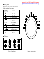
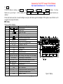
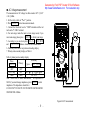
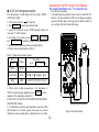
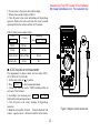
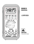
Generated by Foxit PDF Creator © Foxit Software
http://www.foxitsoftware.com For evaluation only.
80000Series
USER’S
MANUAL
D
i
g
i
t
a
lM
u
l
t
i
m
e
t
e
r
F
u
n
c
t
i
o
nG
e
n
e
r
a
t
o
r
1
0– D
i
g
i
tC
o
u
n
t
e
r
Generated by Foxit PDF Creator © Foxit Software
http://www.foxitsoftware.com For evaluation only.
A unique
Multi–functional device
■Features
1 Multi–Display: Primary 80000
Secondary 80000
Bargraph 23 segments
1 Basic DC Accuracy: 0.05%
1 mV Impedance : >1000MΩ
1 More than 50 measuring functions.
1 Frequency measurement : 0.5Hz to 1000.000000MHz
1 16 Frequency points, 1% to 99% duty selectable square wave output.
1 Analyzing component of current or voltage signal.
o80MΩ,10MΩ t
o8000MΩ
1 Resistance : 0.1Ωt
a
p
a
c
i
t
a
n
c
e
:1
P
Ft
o1
0
0
µF
1 C
e
m
p
e
r
a
t
u
r
e
:5
0
℃ t
o1
3
7
2
℃,
5
8
℉ t
o2
5
0
2
℉
1 T
B
m2
0t
y
p
e
so
fr
e
f
e
r
e
n
c
ei
m
p
e
d
a
n
c
e
.
1 d
1 A
u
t
od
a
t
ah
o
l
d
/
p
e
a
kh
o
l
d
.
e
l
a
t
i
v
em
e
a
s
u
r
e
m
e
n
t
.
1 R
1 3
6h
o
u
r
sd
y
n
a
m
i
cr
e
c
o
r
d
i
n
g:
M
A
X
/
M
I
N
/
A
V
G
/
M
A
X
M
I
N
o
m
m
u
n
i
c
a
t
i
o
n:i
s
o
l
a
t
e
do
p
t
i
c
a
lR
S
2
3
2
1 C
i
m
e
rf
o
rm
e
a
s
u
r
e
m
e
n
t
.
1 T
a
c
k
l
i
g
h
td
i
s
p
l
a
y
.
1 B
u
t
op
o
w
e
ro
f
f
1 A
Table
Generated by Foxit PDF Creator © Foxit Software
http://www.foxitsoftware.com For evaluation only.
of Contents
B
r
i
e
f I
n
t
r
o
d
u
c
t
i
o
n--------------------------------------------------1
S
a
f
e
t
y I
n
f
o
r
m
a
t
i
o
n--------------------------------------------------1
F
u
n
c
t
i
o
n O
f M
e
t
e
r --------------------------------------------------1
□T
e
r
m
i
na
l
---------------------------------------------------------1
□R
o
t
a
r
y S
w
i
t
c
h
--------------------------------------------------2
□P
u
s
h B
u
t
t
o
n
--------------------------------------------------2
□D
is
pl
ay ----------------------------------------------------------------5
□S
p
e
c
i
a
l f
u
n
c
t
i
o
n
--------------------------------------------------6
□M
e
a
s
u
r
e
m
e
n
t R
a
n
g
e
s
--------------------------------------------------7
H
o
w t
o O
p
e
r
a
t
e
--------------------------------------------------8
□D
C V
o
l
t
a
g
e m
e
a
s
u
r
e
m
e
n
t
--------------------------------------------------8
□A
C V
o
l
t
a
g
e m
e
a
s
u
r
e
m
e
n
t
--------------------------------------------------9
□A
C/D
C m
i
l
l
i
v
o
l
t
a
g
em
e
a
s
u
r
e
m
e
n
t
--------------------------------------------1
0
□A
C/D
C m
i
l
l
i
a
m
p
e
r
e m
e
a
s
u
r
e
m
e
n
t--------------------------------------------1
1
□A
C/D
C A
m
p
e
r
ec
u
r
r
e
n
tm
e
a
s
u
r
e
m
e
n
t--------------------------------------------1
2
□Res
ista
ncemea
sure
men
t -----------------------------------------------------------13
□C
a
p
a
c
i
t
a
n
c
e m
e
a
s
u
r
e
m
e
n
t --------------------------------------------------1
5
□F
r
e
q
u
e
n
c
y a
n
d r
o
t
a
t
i
o
n
a
l s
p
e
e
d(
R
P
M
) meas
urement---------------------------------16
□T
e
m
p
e
r
a
t
u
r
e m
e
a
s
u
r
e
m
e
n
t--------------------------------------------------1
7
□D
i
o
d
e a
n
d c
o
n
t
i
n
u
i
t
y c
h
e
c
k--------------------------------------------------1
8
□S
q
u
a
r
e w
a
v
e o
u
t
p
u
t --------------------------------------------------1
9
E
l
e
c
t
r
i
c
a
l s
p
e
c
i
f
i
c
a
t
i
o
n
s--------------------------------------------------2
0
□D
C
V--------------------------------------------------2
0
Generated by Foxit PDF Creator © Foxit Software
http://www.foxitsoftware.com For evaluation only.
□A
C
V(
T
r
u
e R
M
S
)-------------------------------------------2
0
□A
C
VA
V
G(
5
0
H
zs
i
n
ew
a
v
ec
a
l
i
b
r
a
t
i
n
g
) --------------------------------------------2
1
□D
C
A--------------------------------------------------2
1
□A
C
A(
T
r
u
e R
M
S
)-------------------------------------------2
1
□A
C
AA
V
G(
5
0
H
zs
i
n
ew
a
v
ec
a
l
i
b
r
a
t
i
n
g
) --------------------------------------------2
2
□d
B
m --------------------------------------------------2
2
□Resistance-------------------------------------------------------------------------22
□D
i
o
d
e--------------------------------------------------2
2
□Fre
quen
cy --------------------------------------------------------------------23
□R
o
t
a
t
i
o
n
a
ls
p
e
e
d(
R
P
M
)--------------------------------------------2
3
□C
a
p
a
c
i
t
a
n
c
e--------------------------------------------------2
3
□S
q
u
a
r
e W
a
v
e O
u
t
p
u
t--------------------------------------------------2
4
□T
e
m
p
e
r
a
t
u
r
e--------------------------------------------------2
4
G
e
n
e
r
a
l s
p
e
c
i
f
i
c
a
t
i
o
n
s--------------------------------------------------2
4
M
a
i
n
t
e
n
a
n
c
e--------------------------------------------------2
5
□G
e
n
e
r
a
lm
a
i
n
t
e
n
a
n
c
e --------------------------------------------------2
5
□B
a
t
t
e
r
yR
e
p
l
a
c
e
m
e
n
t--------------------------------------------2
5
□F
u
s
eR
e
p
l
a
c
e
m
e
n
t--------------------------------------------2
5
A
c
c
e
s
s
o
r
i
e
s--------------------------------------------------2
6
O
p
t
i
o
n
s--------------------------------------------------2
6
RS
23
2ad
ap
t
eri
ns
ta
ll
at
i
on -------------------------------------------------------26
Brief
Generated by Foxit PDF Creator © Foxit Software
http://www.foxitsoftware.com For evaluation only.
introduction
These series have two models.
The 80000 is autorange and calibrated by 50Hz sine signal.
The 8000R is also antorange and can offer true RMS measurement.
Safety
information
Read this operation manual completely before using the meter to ensure that you use the meter safety .follow the safety guidelines as
below :
1 Use the meter only as specified in this manual; Other wise ,the protection provided by the meter maybe impaired.
1 Never measure voltage while the test leads are inserted into the current input terminals.
1 Do not use the meter if it looks damaged .
1 Inspect the leads for damaged insulation or exposed metal , check test lead continuity .Replace damaged leads .
1 Disconnect the power and discharge all high-voltage capacitors before testing in resistance, continuity, and diode function.
1 Be Cautions when working above DC 60V or AC 42V,such voltages may cause a shock hazard .
1 When making measurement ,keep your fingers behind the guards plant on the probes.
1 Select the proper function and range for measurement ,To avoid damaging the meter, disconnect the test leads from test points before
change function.
Function of meter
■ Terminal
About terminal function refer to table 1
Table 1. terminal
Terminal
COM
V/Ω/Hz
mA
10A
Function
Common terminal for all measurement
Volts , Ohm , Diode , Freq. , Temp. and Cap.
measurement and square wave output terminal
milliampere current measurement terminal
Ampere current measurement terminal
Figure 1. terminal
-
1 -
Generated by Foxit PDF Creator © Foxit Software
http://www.foxitsoftware.com For evaluation only.
■ Rotary switch
About rotary switch function refer to table 2
Table 2.functions of rotary switch
Position of
rotary switch
V
V
m
V
Ω
D
U
T
Y
/
H
z
m
A
A
T
E
M
P
O
F
F
Function
AC V
DC V
DC、AC millivoltage
Diode & continuity
Resistance
Duty / Frequency
Capacitance
milliampere current
Ampere current
Squarer wave output
Temperature
Power off
■ Push button
Figure 3. Push button
Figure 2. Rotary switch
-
2 -
Generated by Foxit PDF Creator © Foxit Software
http://www.foxitsoftware.com For evaluation only.
1
.
S
E
L
E
C
T
1 Press this button you can select your measurement mode.
1 When meter as square wave output , press this button can select duty of square wave (1% - 99%).
2
.
R
A
N
G
E
1 When power on meter it at auto range mode ,press this button can select your measurement range.
1 While S
E
Tbutton operating the R
A
N
G
Echange as ▲(moving up) button .Press this button can move setting digits up.
1 Press this push button more than 2 seconds meter return to auto range .
3
.
M
A
X
/
M
I
N
1 Press this button momentary the meter enter dynamic record mode.
1 At dynamic record mode ,press this button momentary again to cycle MAX , MIN ,AVG , MAX-MIN and Present Reading on
secondary display.
1 Press this push button more than 2 seconds meter return to normal mode .
1 At MAX/MIN state the recording time is 36 hours.
E
Tbutton operating the M
A
X
/
M
I
Nchange as ◀(moving left) button .Press this button can move setting digits left.
1While S
4
.
T
i
m
e
r
[
R
S2
3
2
]
1 Press this button more than 2 seconds the meter enter communication on and “RS232” appear on display screen .
1 At communication mode auto power off disable.
1 Press this button more than 2 seconds again the meter exit this mode and return normal state.
1 Setting time for measuring see special functions.
5
.H
1 Press this button meter enter auto data hold mode and “A-H” appear on display screen .
1 The data hold function allows operator to hold the displayed digital value while analog bar graph continues showing the present
reading.
1 At auto hold mode the meter can refresh hold new stable readings and sound point out.
1 Press this button again , the meter enter Peak+ hold mode and a “ PH+” appear on display screen .
1 Press this button again , the meter enter Peak - hold mode and “PH-”appear on display screen .
1 Press this button mare than 2 seconds the meter exit HOLD mode and return to normal state.
6
.
2
n
dV
I
E
W
-
3 -
Generated by Foxit PDF Creator © Foxit Software
http://www.foxitsoftware.com For evaluation only.
1 Use2
n
dV
I
E
Wselect secondary display functions . table 3 shows press 2
n
dV
I
E
Wbutton various measuring states.
Table 3. press 2
n
dV
I
E
Wfor secondary display
Rotary Switch position
V
V
m
V
H
z
/
D
U
T
Y
Measure state
ACV+Hz
AC dBm+Hz
(ACV+DCV)+Hz
dBm+Hz
ACmV+Hz
dBm+Hz
Hz
Primary display
ACV
AC dBm
ACV+DCV
dBm
ACmV
dBm
Hz
Press 2
n
dV
I
E
Wto
change output frequency
Second display
%/ %/ ms/ ms
ACV/Hz
ACV/Hz
Hz/ACV/DCV/ACV+DCV
Hz/ %/ %/ ms/ ms
Hz/ACmV/DCmV/ACmV+DCmV
%/ %/ ms/ ms
Hz/
Press S
E
L
E
C
Tto change duty value
1The meter as square wave output ,press this button can selecting frequency:
0.5000Hz/1.0000Hz/2.0000Hz/10.000Hz/50.000Hz/60.240Hz/74.63Hz/100.00Hz/151.50Hz/200.00Hz/303.00Hz/606.10Hz/1.2500kHz
/1.6660kHz/2.5000kHz/5.0000kHz .
1 Press this button more than 2 seconds the meter return 606.10 Hz, 50% of duty output state .
1While S
E
Tbutton operating the 2
n
dV
I
E
Wchange as ▼(moving down) button .Press this button can move setting digits down.
7
.
R
E
L
△
1 Press this button the meter enter relative measuring state and “REL△” appear on display . In this mode present readings as Relative
reference value and display on secondary . Relative measurement has two mode . one is REL△=measuring value-Reference value ,the
E
L
E
C
T
to select REL△ or REL% mode).
other is REL%=(REL△/Reference value)×100% ( press S
1 While S
E
Tbutton operating ,R
E
L
△button change as ▶ (moving right) button.
1 Set up reference value for measurement .
① In every function use R
A
N
G
Eselect your range.
② After press S
E
Tonce , press S
E
L
E
C
Ttwice the meter enter set up reference value for measurement . At same time the
▲ ▼ ◀ ▶ buttons are started .
③ Use ▲ ▼ ◀ ▶ buttons set your reference value.
④ After set up, you can press S
E
Tto confirming .
1 Press R
E
L
△ button more than 2 seconds the meter return to normal state .
-
4 -
Generated by Foxit PDF Creator © Foxit Software
http://www.foxitsoftware.com For evaluation only.
8
.
S
E
T
1 Press this button to starting ▲[ R
A
N
G
E
] ▼[ 2
n
dV
I
E
W] ◀[ M
A
X
/
M
I
N] ▶[ R
E
L
△ ] buttons . Use these
buttons set up your digits . At this condition the R
A
N
G
E2
n
dV
I
E
W M
A
X
/
M
I
N R
E
L
△ original functions are
disabled.
1 Press this button more than 2 seconds backlight on and press this button again the backlight off. The light can auto off after it on 30
seconds if dos not press this button .
■ Display
Table 4. symbols of display
Order No.
1
2,3,17
4
5
6
7
8
9,19
10
11
12
13
14
15
16
20
21
22
23
24
25
26
27,18
28
Symbol
Hi
REL△%
DC, AC,DC+AC
PH+ PHA-H
AVG
Auto
APO
RS 232
MAX/MIN /MAX-MIN
mV/V/mA/A
Hz / kHz / MHz/Ω/ kΩ/MΩ
% % ms ms
nF / µF
mV/V/mA/A
dBm
Hz / kHz / MHz/Ω/ kΩ/MΩ
℃ ℉
RPM
Description
Analog bar graph
Negative sign
Square wave output
Hi frequency or themocouple indicate
Battery power is weakening
Diode/audible continuity function
Relative measurement
DC,AC, DC+AC voltage or current
+ peak hold, - peak Hold
Auto Hold
Average reading
Auto mode
Auto power off sign
Communication on annunciation
MAX Reading , MIN Reading / MAX-MIN Reading
Second display volt and current unit
Frequency and Resistance (ohms) unit [second]
Duty cycle unit , pulse width unit
Capacitance unit
Primary display volt and current unit
dBm annunciation
Frequency and Resistance (ohms) unit [primary]
Temperature measurement indicate
Round/per minute
-
5 -
Figure 4. Display
Generated by Foxit PDF Creator © Foxit Software
http://www.foxitsoftware.com For evaluation only.
■ Special functions
1 Auto power off
The meter has auto power off function , in normal conditions ,when the meter is power on, if any push buttons are not used or rotary
switch is not changed ,it can auto power off in 30 minutes after power on. Before power off five minutes ,the audible five beepers that
points out the meter will power off .In operating state any push button is used or rotary switch is changed the time of auto power off
will recount.
1 Set up time for measurement
I
M
E
Rbutton to set time [ “0.00.00 ” appear at secondary display].
1. Press T
2. Press S
E
L
E
C
Tbutton the last digit of secondary display flash , at the same time, the ▲ ▼ ◀ ▶ are enable [The first digit
of secondary display is hour, the second and third are minutes , the forth and fifth are seconds] .
1. Use ▲ ▼ ◀ ▶ buttons to selectt digit of time .
2. Press T
I
M
E
Rbutton again to confirming. Complete this procedure measuring time is starting .
1 Set limited measurement
The meter has set up limited or down limited measurement functions, up limited and down limited setting as following .
1. Set Up limited : power on the meter → select range → press S
E
T→ press S
E
L
E
C
Tselect Up limited seting state (secondary
display “
”) → press moving buttons ▲ ▼ ◀ ▶ to set digits → press S
E
Tto confirm .
2. Set Down limited : power on the meter → select range → press S
E
T→ press S
E
L
E
C
Tselect Down limited seting state
(secondary display “
” ) → press moving buttons ▲ ▼ ◀ ▶ to set digits → press S
E
Tto confirm .
3. After setting proceeding measurement .
a. If measuring above limited the secondary display “
” and primary display present value .
b. If measuring down limited the secondary display “
” and primary display present value .
c. If measuring about high and low , secondary display “
”.
1 Analog bar graph
The Function of bar graph is analog needle of meter but without the overload ,and updates 40 times per second because the graph
responds 10 times faster than the digital display it is useful for making peak and null adjustments and observing rapidly changing
inputs .The bar graph has 23 segments .The number of lit segments is relative to the full-scale value of the selected range .The unit of
the bar graph is 4000 counts/bar except when in the relative mode .The polarity indicated at left of the bar graph.
-
6 -
Generated by Foxit PDF Creator © Foxit Software
http://www.foxitsoftware.com For evaluation only.
1 Square wave output
The square wave output is a useful function is let user have free space for application .For instance ,PWM (Pulse Width
Modulation)out ,regulate voltage control, timer to control circuit ,synchronous clock ,etc ,this is a free-for-all application function.
■ Measurement ranges
A measurement range determines the highest value meter can measure ,the meter functions have more than one range.
(1)Being in the right measurement range is important :
1 If the range is too high ,the meter will not display the most accurate measurement ;If the range is too low ,the meter will show “OL”
on the display .
(2)Auto range and manual range ;
1The meter bas both auto range and manual range options :
1 In the auto range (Auto) mode ,the meter selects the best range for the input detected .This allows you to switch test points without
having to reset the range.
1 In the manual range mode you can select the range ,this allows you to override auto range and lock the meter in a specific range.
1 When the meter in auto range mode the “AUTO” sign will be appear on display screen .
(3)To enter or exit manual range mode;
A
N
G
Ebutton momentary the meter enters the manual range mode and “AUTO” turns off.
1 Press R
1 Each press of R
A
N
G
Emomentary increments the range .When the highest range is reached ,the meter wraps to the lowest range.
1 Press R
A
N
G
Emore than 2 seconds the meter returns to auto range mode and “AUTO” appear on display screen .
-
7 -
Generated by Foxit PDF Creator © Foxit Software
http://www.foxitsoftware.com For evaluation only.
How to operate
■ DC Voltage measurement
The measurement of DCV has three modes :DCV / [DCV+ACV]
/ dBm .
1. Set the rotary switch to “
V” position.
2. Press S
E
L
E
C
Tto select measurement mode.
3. Connect the black test lead to “COM” terminal and the red
test lead to “VΩHz” terminal.
4. For auto range mode the meter at auto range , if you want
A
N
G
Eto obtain your range.
some range press R
5. According to your need ,can press R
E
L
△
M
A
X
/
M
I
N
and 2
n
dV
I
E
Wbuttons obtain relevant measurement .
6. Touch the probes to the test points and reading display .
7. Primary and secondary display as Table 5.
Table 5. primary and secondary display
Press
S
E
L
E
C
T
Primary
DCV
DCV
[DCV+ACV]
DCV
[ press
Secondary
2
n
dV
I
E
W]
ACV/Hz
dBm
dBm
Hz/ACV/DCV/DCV+ACV
Note: When enter to dBm measurement , the impedance is
600Ω,if you want change impedance, press R
A
N
G
Eto select
impedance .The impedance selectable is:
4/8/16/32/50/75/93/110/125/135/150/200/250/300/500/600/800/
900/1000/1200 of Ohms .
-
8 -
Figure 5.DCV measurement
■ AC Voltage measurement
The measurement of AC voltage bas three modes :ACV / [ACV
+ Hz ] / dBm.
1. Set the rotary switch to “
V ” position.
2. Press S
E
L
E
C
Tto select measurement mode .
3. Connect the black test lead to “COM” terminal and the red
test lead to “VΩHz” terminal.
4. For auto range mode the meter at auto range mode, if you
A
N
G
E to obtain your range.
want some range please press R
5. According to you need can press R
E
L
△
M
A
X
/
M
I
N
and 2
n
dV
I
E
W buttons obtain relevant measurement.
6. Touch the probes to the test points and reading display.
7. Primary and secondary display as Table 6 .
Generated by Foxit PDF Creator © Foxit Software
http://www.foxitsoftware.com For evaluation only.
Table 6. primary and secondary display
Secondary
Press
Primary
S
E
L
E
C
T
[ press 2
n
dV
I
E
W]
ACV
ACV
[ACV+Hz]
ACV
Hz / % / % / ms / ms
dBm
dBm
Hz / ACV
Note: When enter to dBm measurement , the impedance is
600Ω,if you want change impedance, press R
A
N
G
Eto select
impedance .The impedance selectable is:
4/8/16/32/50/75/93/110/125/135/150/200/250/300/500/600/800/
900/1000/1200 of Ohms .
Figure 6.ACV measurement
-
9 -
■ AC/DC millivoltage measurement
The measurement of millivoltage has three modes: DCmV /
[ACmV+Hz] / dBm:
1. Set the rotary switch to “
mV” position.
2. Press S
E
L
E
C
Tto option measurement mode .
3. Connect the black test lead to “COM” terminal and the red
test lead to “VΩHz” terminal .
4. According to your need can press R
E
L
△
M
A
X
/
M
I
N
and 2
n
dV
I
E
Wpush buttons obtain relevant measurement
5. Touch the probes to the test points and reading display .
6. Primary and secondary display as Table 7.
Generated by Foxit PDF Creator © Foxit Software
http://www.foxitsoftware.com For evaluation only.
on result of measurement.
3.At millivoltage measurement mode in order to obtain DC+AC
function , the input terminal of ADC do not employed coupling
capacitor. Therefor please never apply more than the double dc
or ac voltage of the rated value of this range.
Table 7. primary and secondary display
Secondary
Press
Primary
S
E
L
E
C
T
[ press 2
n
dV
I
E
W]
DCmV
DCmV
[ACmV+Hz]
ACmv
dBm
dBm
Hz/
%/
%/
ms/
ms
Hz/ACmV/DCmV/[DCmV+ACmV]
Note:
1. When enter to dBm measurement , the impedance is
600Ω,if you want change impedance, press R
A
N
G
Eto select
impedance .The impedance selectable is:
4/8/16/32/50/75/93/110/125/135/150/200/250/300/500/600/800/
900/1000/1200 of Ohms .
2. At millivoltage mode the input impedance more than 1000
MΩ,therefore at test leads opening state input easy caused
interference .Some random digits on display but have not effect
-
Figure 7.mV measurement
10 -
Warning
For Current
Generated by Foxit PDF Creator © Foxit Software
http://www.foxitsoftware.com For evaluation only.
measurement
To avoid damage to meter or injury, if the fuse blows .Never
attempt an in-circuit current measurement .Where the
open-circuit potential to earth is greater than 1000V. To
avoid damage to the meter ,check the meter’s fuses before
proceeding. Use the proper terminals , function and range
for your measurement . Never place the probes in parallel
with a circuit or component when the leads are plugged into
the current terminals. Never test voltage when test lead plug
in “mA” or “10A” terminal !
Warning to wrong operation when probes are plugged in to
the “mA” or “10A” terminal and the rotary switch is not at
“
mA” or “ A” position, meter will beeper warning to
wrong operation until rotary switch at right position or
probes pull out “mA” or “10A” terminals .
■ AC/DC milliampere current measurement
The measurement of milliampere has four modes: DCmA /
ACmA / [DC mA +ACmA] / [ACmA+Hz].
1. Set the rotary switch to “
mA” position.
E
L
E
C
Tto select measurement mode.
2. Press S
3. Connect the black test lead to “COM” terminal and the red
test lead to “mA”terminal.
4. According to your need can press R
E
L
△
M
A
X
/
M
I
N
buttons obtain relevant measurement .Turn off power to the
circuit, discharge all high-voltage capacitors .
5. Break the circuit path to be tested . Touch the black test lead
to more negative side of the break ;Touch the red test lead to the
more positive side of the break .
-
11 -
Figure 8.mA current measurement
Generated by Foxit PDF Creator © Foxit Software
http://www.foxitsoftware.com For evaluation only.
6. Turn on power to the circuit , then read the display.
7. Primary and secondary display as Table 8 .
8. Turn off power to the circuit and discharge all high-voltage
capacitors .Remove the meter and restore the circuit to normal
operation .Pull out the red test lead from “mA” terminal.
Table 8. primary and secondary display
Press
Secondary
Primary
[press 2
S
E
L
E
C
T
n
dV
I
E
W]
DCmA
DCmA
ACmA
ACmA
DCmA+ACmA DCmA+ACmA
ACmA+Hz
ACmA
ACmA
Hz
■ AC/DC Ampere current measurement
The measurement of ampere current has four modes: DCA /
ACA / [DCA+ACA] / ACA+Hz
1. Set the rotary switch to “ A” position.
E
L
E
C
T to select measurement mode.
2. Press S
3. Connect the black test lead to “COM” terminal and the red
test lead to “10A”terminal.
4. According to your need can press R
E
L
△ M
A
X
/
M
I
N
buttons obtain relevant measurement.
5. Turn off power to the circuit, discharge all high-voltage
capacitors.
6. Break the circuit path to be tested . Touch the black test lead
to more negative side of the break .Touch the red test lead to
-
12 -
Figure 9.Ampere current measureme
Generated by Foxit PDF Creator © Foxit Software
http://www.foxitsoftware.com For evaluation only.
the more positive side of the break.
7. Turn on power to the circuit, then read the display.
8. Primary and secondary display as Table 9.
Table 9. primary and secondary display
Press S
E
L
E
C
T
DCA
ACA
DCA+ACA
ACA+Hz
Primary
Secondary[ press
DCA
ACA
DCA+ACA
ACA
2
n
dV
I
E
W]
ACA
Hz
9. Turn off power to the circuit and discharge all high-voltage capacitors .Remove the meter and restore the circuit to normal
operation .Pull out the red test lead from “10A” terminal.
■ Resistance Measurement
Caution
To avoid damage to meter or to the equipment under test ,disconnect circuit power and discharge all high-voltage capacitors
before measuring resistance.
E
L
E
C
T button to select these mode.
The measurement of resistance has three modes : normal ,continuity and Hi resistance . Use S
1 Normal mode
1. Set the rotary switch to “Ω” position.
2. Connect the black test lead to “COM” terminal and the red test lead to “VΩHz” terminal.
3. Touch the probes to the test points and reading display.
Note: The test leads can add 0.1Ω ~ 0
.
5
Ω of error to resistance measurement, please short test leads and press R
E
L
△ .
4. According to your need can press R
E
L
△
M
I
X
/
M
I
N buttons obtain relevant measurement .
1 Continuity mode
At normal mode press S
E
L
E
C
Tuntil “
” sign appear on the display screen . If checking points resistance fall below 50Ω the
-
13 -
Generated by Foxit PDF Creator © Foxit Software
http://www.foxitsoftware.com For evaluation only.
beeper will sound .
1 Hi resistance mode
At normal mode press S
E
L
E
C
Tuntil “ Hi ” sign appear on display screen .Using this function can measure above 80MΩresistance .
Figure 10.resistance measurement
-
14 -
Generated by Foxit PDF Creator © Foxit Software
http://www.foxitsoftware.com For evaluation only.
■ Capacitance Measurement
Caution
To avoid damage to the meter or to the equipment under test disconnect circuit power and discharge all high-voltage capacitors
before measuring capacitance . Use the DC voltage function to confirm that the capacitor is discharged.
1. Set the rotary switch to “ ” position.
2. Connect the black lead to “COM” terminal and the red test lead to “VΩHz” terminal.
3. Touch the probes to capacitor’s legs , if the capacitor is a polarity ,The red test lead to the positive leg.
A
N
G
Eoption your range , with this method can speedup measurements of similar values .
4. Press R
5. According to your need can press R
E
L
△
M
A
X
/
M
I
N buttons obtain relevant measurement.
Figure 11.capacitance measurement
-
15 -
Generated by Foxit PDF Creator © Foxit Software
http://www.foxitsoftware.com For evaluation only.
■ Frequency and rotational speed (RPM) measurement
1. Set the rotary switch to “ Hz ” position .
2. Press S
E
L
E
C
Tto select normal , Hi Hz and RPM three
Measuring Mode .
3. Connect the probes to signal source and reading display.
4. In normal mode the meter auto ranges to one of six
frequencies: 999.99Hz / 9.9999kHz / 99.999kHz / 999.99kHz /
8.0000MHz.
n
dV
I
E
Wcan change % / % / ms / ms.
5. Press 2
6. In Hi Hz mode, using Hi Frequency accessory to measure
more than10MHz Frequency ,The reading is 10-Digit
counter [ primary display + second display ].
7. In RPM mode, using rotational speed accessory to measure
rotational speed and the reading is RPM .
Figure 12.freq. and rotational speed measurement
-
16 -
■ Temperature measurement
1. Set the rotary switch to “ TEMP ” position.
2. Press S
E
L
E
C
Tto select Hi or normal test mode.
3. In Hi mode using type K thermocouple to measure
temperature.
4. Plug the red leg ( + ) to “ VΩHz ” terminal and the black
leg( - )to “ COM ” terminal and reading display.
E
L
E
C
Tto “Hi” off the reading is room temperature .
5. Press S
6. Measurement range: -50℃ - 1300℃ ,
-58℉- 2502℉.
7. Display : primary ℃ ,
secondary ℉.
Generated by Foxit PDF Creator © Foxit Software
http://www.foxitsoftware.com For evaluation only.
Figure 13.temp. measurement
-
17 -
Generated by Foxit PDF Creator © Foxit Software
http://www.foxitsoftware.com For evaluation only.
■ Diode and continuity check
Caution
To avoid possible damage to the meter or to the equipment
under test , disconnect circuit power and discharge all
high-voltage capacitors before checking diodes.
1. Set the rotary switch to “
” position .
2. Connect the black test lead to “ COM” terminal and the red
test lead to “ VΩHz” terminal.
3. For diode checking, touch the red test lead to the positive side
of the diode and the black test lead to the negative side .The
meter can display diode voltage drop . A good product a forward
bias reading of 0.5V to 0.8V.
4. Reverse the probes and measure the voltage across the diode
again if the diode good “OL” is displayed.
Note:
(1) Near 0V drop is displayed in both directions the diode
shorted .
(2) “OL” is displayed in both directions the diode opened.
5. For continuity checking , while testing continuity , the
beeper will sound if the resistance falls below 50Ω.
Figure 14.diode and continuity check
-
18 -
Generated by Foxit PDF Creator © Foxit Software
http://www.foxitsoftware.com For evaluation only.
■ Square Wave Output
This meter can output square wave that frequency is selectable
by 2
n
dV
I
E
W
: 0.5000Hz / 1.0000Hz / 2.0000Hz /
10.000Hz / 50.000Hz / 60.240Hz / 74.63Hz / 100.00Hz /
151.50Hz / 200.00Hz / 303.00Hz / 606.10Hz / 1.2500kHz /
1.6660kHz / 2.5000kHz / 5.0000kHz.
1. Set the rotary switch to “
” position.
2. Connect the black test lead to “COM” terminal and the red
test lead to “VΩHz” terminal.
E
L
E
C
Tto select the duty of 1% to 99% .The square
3. Press S
wave output from “COM” and “VΩHz” terminal or test leads.
4. Primary and secondary display as Table 10.
Table 10. primary and secondary display
Primary
Secondary
Function
n
dV
I
E
W]
E
L
E
C
T]
[ press 2
[ press S
Hz
%
5. Press 2
n
dV
I
E
Wmore than 2 seconds the meter return to
606.10Hz / 50% duty output state .
Figure 15 . square wave output
-
19 -
Generated by Foxit PDF Creator © Foxit Software
http://www.foxitsoftware.com For evaluation only.
Electrical Specifications
Accuracy is specified for one year after calibration at operating temperatures of 18℃ t
o2
8
℃ ,w
i
t
hr
e
l
a
t
i
v
eh
u
m
i
d
i
t
ya
t0%t
o
7
5
%
.
A
c
c
u
r
a
c
ys
p
e
c
i
f
i
c
a
t
i
o
n
st
a
k
et
h
ef
o
r
mo
f
:
±(a% of reading +number of least significant digits).
■ Table 11. DCV
Range
Resolution
80mV
1µV
800mV
10µV
8V
0.1mV
80V
1mV
800V
10mV
1000V
0.1V
■ Table 12. ACV
Range
Resolution
80m
V
80
0mV
8V
Accuracy
Note
±(0.05% rdg+10)
Input impedance: 80mV—800mV>1000MΩ
8V—1000V : 10MΩ
±(0.08% rdg+10)
( True RMS )
Accuracy
50H
z /60
Hz
50H
z— 1
kH
z
1kH
z— 1
0k
Hz
10k
Hz — 20
kHz
1μV
±(0.8
%rd
g+
10)
±(1.2
%r
dg+1
0)
±(3.0
%r
dg+1
0)
±(8.0
%r
dg+1
0)
10μV
0.
1mV
±(0.8
%r
dg+1
0)
±(0.8
%r
dg+1
0)
±(1.2
%r
dg+1
0)
±(1.2
%r
dg+1
0)
±(3.0
%r
dg+1
0)
±(3.0
%r
dg+1
0)
±(5.0
%r
dg+1
0)
±(5.0
%r
dg+1
0)
80
V
1m
V
750
V
10m
V
50H
z— 4
00
Hz:±(1.0
%r
dg+5)
Input impedance: 8mV—800mV>1000MΩ
8V—1000V 10MΩ ,Parallel capacitance<100pF
-
20 -
■ Table 13. ACV AVG
Range
80
mV
8
00m
V
8
V
80V
75
0V
Resolution
1μV
10μV
0.
1mV
1mV
10m
V
Generated by Foxit PDF Creator © Foxit Software
http://www.foxitsoftware.com For evaluation only.
( 60Hz Sine Wave Calibrating )
Accuracy
50H
z /60
Hz
±(1.0%rd
g+8)
±(0.8%rd
g+8)
±(0.8%rd
g+8)
50H
z— 1
kH
z
±(1.5%rd
g+
8)
±(1.5%rd
g+
8)
±(1.0%rd
g+
8)
1kH
z— 1
0k
Hz
±(4.0%rd
g+
8)
±(4.0%rd
g+
8)
±(3.0%rd
g+
8)
10k
Hz — 20
kHz
±(8.0%rd
g+
8)
±(8.0%rd
g+
8)
±(5.0%rd
g+
8)
50H
z— 4
00
Hz:±(1
.0%rd
g+ 5)
Input impedance: 8mV—800mV>1000MΩ
8V—1000V , 10MΩ Parallel capacitance<100pF
■ Table 14. DCA
Range
Resolution
80mA
1µA
800mA
10µA
8A
0.1mA
10A
1mA
Accuracy
Note
Fuses :F 800mA/250V F 10A/250V
Voltage drop: ≤800mV
±(0.5% rdg+10)
■ Table 15. ACA ( True RMS )
Range
Resolution
Accuracy
80mA
1µA
50Hz — 2kHz
800mA
10µA
8A
0.1mA
±(0.8% rdg+10)
10A
1mA
Note
Fuses : F 800mA/250V F 10A/250V
Voltage drop: ≤800mV
-
21 -
■ Table 16. ACA AVG (60Hz Sine Wave Calibrating )
Range
Resolution
Accuracy
80mA
1µA
50Hz — 500Hz
800mA
10µA
±(0.8% rdg+10)
8A
0.1mA
10A
1mA
■ Table 17. dBm
Function
Range
dBm
-80.00dBm — +80.00dBm
■ Table 18. Resistance(Ω)
Range
Resolution
800Ω
0.01Ω
8KΩ
0.1Ω
80kΩ
1Ω
800kΩ
10Ω
8MΩ
100Ω
80MΩ
1kΩ
±(2.5 % rdg+8)
Generated by Foxit PDF Creator © Foxit Software
http://www.foxitsoftware.com For evaluation only.
Note
Fuses : F 800mA/250V F 10A/250V
Voltage drop: ≤800mV
Accuracy
±1.0% rdg
Resolution
0.01dBm
Accuracy
Note
Note
±(0.3% rdg+10)
Overload protection: 250V RMS
60MΩ — 80MΩ: ±(3.5% rdg+10)
■ Table 19. Diode
Function
Range
Accuracy
Resolution
Diode
8.0000V
±(3.0% rdg+5)
0.0001V
Note
Diode positive Voltage drop
Overload protection: 250V RMS
-
22 -
■ Table 20. Frequency (Hz)
Function
Range
999.99Hz
9.9999kHz
99.999kHz
999.99kHz
Frequency
8.0000MHz
10.0MHz
100.0MHz
1000.0MHz
Generated by Foxit PDF Creator © Foxit Software
http://www.foxitsoftware.com For evaluation only.
Accuracy
±(0.05% rdg+5)
±(0.1% rdg+5)
■ Table 21. Rotational speed (RPM)
Range
Accuracy
Rotational speed
99999
±(0.1% rdg+5)
■ Table 22. Capacitance
Range
Resolution
1nF
1pF
10nF
10pF
100nF
100pF
1µF
1nF
10µF
10nF
100µF
100nF
Resolution
0.01Hz
0.1Hz
1Hz
10Hz
100Hz
1kHz
10kHz
100kHz
Note
Overload protection: 250V RMS
Sensitivity : 0.7V RMS
Plus adapter
Resolution
1RPM
Accuracy
±(5.0% rdg+10)
Note
Plus adapter
Note
±(2.5% rdg+10)
Overload protection: 250V RMS
±(3.5% rdg+10)
-
23 -
Generated by Foxit PDF Creator © Foxit Software
http://www.foxitsoftware.com For evaluation only.
■ Table 23. Square wave output
Description
3V a
p
p
r
o
x
.
0.5Hz ~ 5000Hz
1% ~ 99%
Voltage amplitude
Frequency
Duty cycle
■ Table 24. Temperature
Temp
-50℃ ~ 1372℃
-58℉ ~ 2502℉
Accuracy
±(2.5% rdg+8)
Resolution
1℃
1℉
Note
type K themocouple
General Specification
Maximum voltage between any terminal and earth ground: 1000V RMS
Continuity Beeper : 3kHz Approx.
Display: Double Digital:
80000
Bar graph :
23 segments , update 40 time/sec
Temperature:
Operating: 0℃to+50℃ Storage: -20℃to+60℃
.Altitude:
Operating: under 2000m Storage : under 10,000m
Relative Humidity:
≤75% at 0℃ to +40℃ ≤45% at +40 ℃ to +50℃
Battery Type:
9V zinc , NEDA 1604 or 6F22 or 006p.
Battery Life:
Alkaline : ~500hrs, carbon-zinc: 200hrs typical.
Size:
37×90×190mm
Weight:
650g
Electromagnetic Compatibility: in a RF field of 1V/m on all. ranges and function except Capacitance: total Accuracy = specified +5%
of range Capacitance not specified in RF fields performance above 1V/m is not specified.
Safety / Compliance: IEC 61010 CATⅡ 1000V CATⅢ 600V.
-
24 -
Generated by Foxit PDF Creator © Foxit Software
http://www.foxitsoftware.com For evaluation only.
Maintenance
This meter is a precise device, Do not attempt to repair or service your meter unless you are qualified to do so and have the relevant
calibration performance test ,and service information.These products are intelligent meters , use self-calibrating technology .To avoid
the specification error.All components not replaced except that if is specified.
■ General Maintenance
Periodically wipe the case with a damp cloth and mild detergent .Do not use abrasives or solvents .Dirt or moisture in the terminals can
affect readings. To clean the terminals:
1. Turn the meter OFF and remove all test leads .
2. Clean out any dirt that may be in the terminal .
3. Soak a new swap with a cleaning and oiling agent.
4. Work the swab around in each terminal the oiling agent insulates the terminals from moisture Related contamination .
■ Battery Replacement
Waring
To avoid electrical or are blast , or personal Injury or damage to the meter, use specified fuses ONLY in accordance with the
following procedure
The meter is powered by a 9V battery (NEDA 1604, 6F22, 006P),Replace battery if the low battery sign“
” displayed .Use the
following procedures to replace the battery :
1. Set the rotary switch to “OFF” position .
2. Pull up test leads from terminals.
3. Loosen the screws on battery case , Pull up and move the case.
4. Replace the defective battery.
5. Reverse the procedure of opening to close the battery case .
■ Fuse Replacement
Warning
To avoid electrical shock or personal injury, remove the test leads and any input signals before replacing the Fuses .To prevent
damage or injury, install ONLY replacement fuses with the ampere, voltage, and speed ratings specified.
1. Perform steps 1, 2, 3, 5, of battery replacement procedure.
-
25 -
2. Install new fuse of some size and rating.
Generated by Foxit PDF Creator © Foxit Software
http://www.foxitsoftware.com For evaluation only.
personal computer. See the follow figure
3. Execute the software to take the date for your necessary.
Accessories
Manual
Test leads
Battery (9V)
Protective holster
1
1
1
1
Options
80KP-1 Rotational speed adapter
80KP-2 Hi frequency adapter
RS-232 Package
TP-03
Type K termocouple
RS232 adapter installation
This meter has a communication capability. This function will
assist user to recording and keeping data easy. We have offer
RS232 ADAPTER to optional accessories. The RS232
ADAPTER include a cable with photoelectric receiver and a
software disc. We will continuous release new version per
year .So you can contact the place of purchase to update the
software.
Please refer following procedures if you want to communicate
with personal computer.
1. Power on the meter and then press the T
I
M
E
R
push button more than 2 seconds, the symbol
“R
S
2
3
2” will appear on the display.
Figure 16.
2. Fixes one side of cable to the holster of meter and connect the
9 pin's terminal of cable to communication port 1 or 2 of
-
26 -
RS232 adapter installation