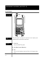
1
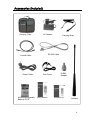
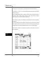
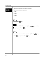
1 2 Safety Term and Symbols Danger statements identify condition or practices that could result in injury or loss of life. Caution statements identify conditions or practices that could result in damage or fire. . Ground statements identify conditions or practices that could connect protective conductor. 3 Caution for safety Prohibiting to removal the cover Do not remove the instrument cover to access the internal components. Only B&K Precisions’ Service technician with knowledge of the instruments’ condition and dangerous voltages can repair the instrument. Instruments that appear damaged or defective should be made inoperative and secured against unintended operation until they can be repaired by qualified service personnel. Keep the clean on power insert Instrument’s power insert should remain dust free. Clean the power insert regularly. Dust could result in damage to this instrument. Continually clean the dust on input terminal of RF frequency counter. Clean the input terminal regularly. Dust could result in damage to the instrument. RF in/output rating Rating of RF input and output connector Maximum DC voltage rating RF input connector (socket): N type female, 50Ohms Maximum RF input power: 5Vrms Caution: Do not use over 5Vrms supplied and/or (-) power could result in damage to this instrument Do not operate this instrument if there is any doubt it is functioning properly: if operating personnel feels the instrument is not operating properly, return this instrument to B&K Precision for service and repair to ensure the safety features are maintained. 4 DC Power The operating Personnel must use the DC adaptor supplied with this instrument. Other adaptors could result in damage to this instrument and it is the limitation of warranty Exterior DC input connector should be matched with polar. DC connector tip must attach with (+) polar grounding. The operating personnel must use grounded power Restore this instrument Instrument care *Avoid direct light *Keep away the heating system *Avoid high temperature (Ex. Inside of the car during the summer time) *Keep away from liquids *Avoid high moisture and/or poor ventilation *Keep away from dust and/or smoke *Avoid extremely low temperature 5 B&K Precision 2640 Ni-MH battery is rechargeable. Charging is controlled from the power of the battery cell and the temperature of the battery. Ni-MH Rechargeable battery is going to increase temp slowly until the temperature is extremely higher. Battery charging is finished automatically by checking the degree of the temperature (dT/dt). For battery protection, when the power of Battery cell is increased, comparing regular temperature and/or exterior temperature degree of when the temperature increases over 50 degrees, battery charging will be finished automatically. Operating personnel must use Ni-MH Rechargeable Battery and do not operate in an explosive atmosphere. - The battery usage time can change due to the using term, environment and temperature. - When battery consumption is large battery-running time will decrease. Operating personnel should phase in a new battery when battery-running time is less than half of the initial operating time. - Operating personnel should not use this instrument and/or keep the battery in place for long periods of time, which could result in discharge of the battery. - To avoid damages to battery, when battery is low, this instrument will turn off automatically. 6 Warranty Limited One-Year Warranty B&K Precision warrants to the original purchaser that its products and the component parts thereof, will be free from defects in workmanship and materials for a period of one year from date of purchase from an authorized B&K Precision distributor. B&K Precision will, without charge, repair or replace, at its option, defective product or component parts. Returned product must be accompanied by proof of the purchase date in the form of a sales receipt. To obtain warranty coverage in the U.S.A., this product must be registered by completing the warranty registration form on www.bkprecision.com within fifteen (15) days of purchase. Exclusions: This warranty does not apply in the event of misuse or abuse of the product or as a result of unauthorized alterations or repairs. The warranty is void if the serial number is altered, defaced or removed. B&K Precision shall not be liable for any consequential damages, including without limitation damages resulting from loss of use. Some states do not allow limitations of incidental or consequential damages. So the above limitation or exclusion may not apply to you. This warranty gives you specific rights and you may have other rights, which vary from state-to-state. B&K Precision 22820 Savi Ranch Parkway Yorba Linda, CA 92887 www.bkprecision.com 7 Accessories (included) Carrying Case AC Adaptor RS-232 Cable Coaxial Cable Power Cable Ni-MH(Rechargeable Battery) 6PCS Carrying Strap Ear Phone User’s Manual N-BNC Adaptor Software CD Antenna 8 Table of contents 1. Introduction Overview……………………………….……………………………..……………….11 2. Features Main features …………………………………………………………………….…12 3. Functions RF Field Strength Analyzer…………………………………………………..…….13 Frequency Counter……………………………………………………….………….13 Specifications………………………………………………………………...……….14 4. Instrument overview Front Panel………………………………………………………………………...….18 Rear Panel…………………………………………………………………………….20 Side Panel…………………………………………………………………………….21 Top Panel…………………………………………………………………………..….22 5. Basic operation Before Power On…………………………………………………………….……….23 Power On……………………………………………………………………………...24 Turn on Power of Instrument………………………………..…………………….25 Description of operation screen…………………………..……………………….26 Reception Mode……………………………………………………………..……….32 Sweep Mode………………………………………………………………………….33 Set up Span……………………………………………………………………..…….34 Frequency Input……………………………………………………..………………. 35 Adjust Screen Level…………………………………………………….………….37 Run - Scanning…………………………………………………..….……………….38 Marker…………………………………………………………..…………………….39 Power Meter…………………………………………………………………………46 Setting of attenuator………………………………………………………………….49 LCD Light……………………………………………………………………………...50 LCD Contrast………………………………………………………………………….51 Buzzer ON/OFF……………………………………………………..……………….52 9 Save/Load………………………………………………………….………………….53 Frequency Counter…………………………………………………………….…….57 Power Source………………………………………………………………..……….59 Level Unit………………………………………………………………………..…….60 Reset………………………………………………………………………………..…61 Baud Rate…………………………………………………………………………..…62 Connection for PC……………………………………………………………………63 Auto Power……………………………………………………………………………64 Offset…………………………………………………………………………..………65 Menu……………………………………………………………..…………………….66 System……………………………………………………………..…….……………70 6. Description of key operating Run [GHz] …………………………………………………………………….………73 Mode [MHz] ………………………………………………………………..…………73 Sweep [kHz] …………………………………………………………….……………74 Marker [DEL] …………………………………………………………………………74 No. 1 [Start/Stop] …………………………………………………….………………75 No. 2 [Span] ………………………………………………………………..…………75 No. 3 [Level] …………………………………………………………………….……76 No. 4 [Single]…………………….…………………………..………………………76 No. 5 [Multi]…………………………………………………………………………77 No. 6 [UNIT] ……..…………………………………………..………………………77 No. 7 [LCD Light] ……………………………………………………….……………78 No. 8 [LCD CONT; LCD Contrast] …………………………………………………78 No. 9 [Attenuator] ……………………………………………………………………79 No. 0 [system] …………………………………………………………..……………79 Shift……………………………………………………………………………….……80 Dot [Buzzer] ……………………………………………………………..……………80 Menu [Load] ………………………………………………………………….………81 Enter [Save] …………………………………………………………….……………81 Up/Down Keys and Knob Key………………………………………………………82 10 Introduction (section 1) Overview The B&K Precision 2640 handheld RF Field Strength Analyzer is optimized to analyze signals from many different source for multiple applications. The B&K Precision 2640 has adopted a synthesizer method and has a wideband reception range of 100 kHz to 2,000 MHz. The characteristic of frequency response of the B&K Precision 2640 is calculated by memorized calculation data from a “look up table”, and so it enables the B&K Precision 2640 to measure accurate levels and make easy analysis of a wide range of frequency bands. The B&K Precision 2640 provides various functions and user-friendly interface which makes it easy to use. The handheld RF Field Strength Analyzer is ideal for users to test, install and maintain Mobile Telecommunications Systems, Cellular and Cordless Phone, CB Paging, Paging Systems, Cable and Satellite TV Systems as well as antenna site measurements and maintenance. The B&K Precision 2640 supports RS 232C serial communication and has separate GUI software. So, user can control the B&K Precision 2640 easily after connecting the B&K Precision 2640 with a personal computer, and can utilize the analyzed data variously after converting or saving numerical value or graph. 11 Features (section 2) Main features 12 100 kHz to 2,000 MHz measurement range Frequency Spectrum Counter Function Measure N-FM, W-FM, AM, SSB signals Demodulate W-FM signals Built-in 2 GHz Frequency Counter Accurate Signal Level Measurement Marker/Delta Marker/Squelch Adjustment Function PLL tuning system for precise frequency tuning Built-in Speaker 192 Pixels X 192 Pixels Back Light LCD Menu selection method for Function selection RS-232C Interface User-friendly Icon Display Maintenance of Wireless Telecommunications Equipments General Usage for Installation Telecommunications Equipments Installation and Maintenance of Cable RFID Tag RF Strength Measurement Installation and Maintenance of Satellite Antenna Detection of Tapping and Hidden Camera Analyzing Function and and Frequency Maintenance of Functions (section 3) RF Field Strength Analyzer Spectrum: Peak Search, Marker to Center, Internal Attn.: The input range can be extended by internal Max 10 dB Attn. function. Sweep Mode: Single Run, Free Run, Squelch Run Selectable Squelch Function: The Squelch Level may be adjusted to any value from the reference level to Full Scale. Frequency Counter Frequency range: 35 MHz to 2,000 MHz No. of digits: 7 digits Resolution: 1 kHz 13 Specifications Frequency Frequency Range 100 kHz to 2,000 MHz Resolution Min. 6.25KHz Multiples Accuracy W-FM / N-FM / AM / SSB ± 4.5 PPM Wide FM : Approx. 180 kHz @-6 dB Narrow FM : Approx. 12.5 kHz @-6 dB AM/SSB : Approx. 2.4 kHz @-6 dB AM, SSB, Narrow FM : 6.25kHz, 12.5kHz Step Range Wide FM : 6.25~125kHz (Multiple of 6.25 kHz) 125~2500kHz (Multiple of 125 kHz) AM, SSB, Narrow FM : 1MHz, 2MHz Span Range Wide FM : 1~20MHz (Multiple of 1 MHz) 20~400MHz (Multiple of 20 MHz) Frequency Selection Mode Amplitude Measurement Range Average noise Level -45 dBm to –110 dBm Wide FM : -100 dBm Max. Narrow FM : -110 dBm Max. AM/SSB : -100 dBm Max. Amplitude Units dBm, dBmV, dBuV Reference Level ±3.0 dB (typical) @ 400KHz to 600KHz Accuracy Reference Level Range Log Scale ±2.0 dB @ over 600KHz 0 dBm to –80 dBm 0.2 dB/DIV min, in 0.25 dB Span (5 Display Division) Internal Attn 10 dB Internal Attn ±1.0 dB (@25 ℃) Accuracy 14 Center, Start/ Stop, Span Specifications Sweep Speed Trigger Source Trigger Mode Memory Display Free Run / Single Run / Continuous Wave / Squelch Run TTL Level Marker Mode Maker / Delta Maker Trace & Setup Storage Type LCD Light Counter Narrow FM / Wide FM / AM / SSB Trigger Level Display Resolution Frequency Min. 500 msec Frequency Range Resolution Accuracy Sampling Time Max 100 Waveforms and 100 States Mono STN LCD 192 Pixels X 192 Pixels On / Off 35 MHz to 2,000 MHz 7 Digits ±50 PPM ±1 COUNT 1 sec Input Sensitivity 35 MHz to 2,000 MHz : 150 mVrms Input Impedance 50 Ohms Max. Input Voltage 5 Vrms Max. 15 Specifications Spectrum RF Input Connector input Port Max Input Level Operation Operating Environment Temperature Humidity N type Female, 50 Ohms Max. +10 dBm, 5Vrms 0 ℃ to 40 ℃ 35 RH to 85 RH Storage Temp. 10 ℃ to 50 ℃ Power Battery Power AA Type Ni-MH Rechargeable Battery × 6 Source Source PCS Battery AA Type 1.2 V, 2,700 mAh Rechargeable Specification Nickel Metal Hydride Battery SMPS Type AC Adapter (DC 12 V Output) Adapter Auto Power On/Off A Car-Adapter (DC 12 V Output) Off/ 5 min./ 10 min./ 20 min./30 min. The B&K Precision 2640 can be quickly recharged using Ni-MH Rechargeable Batteries. The Recharged method of Ni-MH Battery is controlled by the voltage of the Battery Cell and the temperature of Battery. The external temperature of Ni-MH Rechargeable Battery is gradually increased and then quickly increased in some point of time. The B&K Precision 2640 closes charging quickly after checking the increased amount (dT/dt) of external temperature of Battery for a unit time. Also, for Battery protection, the recharging is compulsory closed by builtin temperature sensor in case that the voltage of Battery Cell will be increased to more than some specified level or the external temperature of Battery will be going up to over 50C. For safe usage, it is strongly recommended to use Ni-MH Rechargeable battery, and please do not use in the place with high temperature or high humidity during recharging. 16 Specifications Physical Dimension Specifications Weight 4 ”(W)×9 ”(H)×1.8 ”(D) Approx. 0.66 Kg(1.45 lbm) (including Antenna, except Battery) Standard Antenna (Receive Only), SMPS Type AC Adapter, Fuji-AA type NI-MH Accessories Rechargeable Battery (6 PCS, 1.2 V 2,700 mAh), Manual, Coaxial Cable, Earphone, Carrying Case, Carrying Belt, RS-232C Cable, Adapter(N-BNC), Software for PC Application Specifications and information is subject to change without notice. For the most current product information please visit www.bkprecision.com 17 Instrument overview (section 4) Front Panel Front Figure Run GHz Mode Sweep MHz kHz 1 2 3 4 5 6 7 8 9 Shift 0 . Power Menu Enter Marker DEL The LCD screen can display the signal input level, frequency and LCD amplitude values, and the relative system data Key Pad Power Key Key to turn ON/OFF the system Run / Mode / Sweep / Marker Key Run Key to run the Scanning or input the GHz unit for frequency value input 18 Front Panel Mode Key to set up the Reception Mode or input the MHz unit for frequency value input Sweep Key to set up the Sweep Mode or input the kHz unit for frequency value input Marker Key to select the Marker Function: Marker, Delta Marker, Squelch Marker, Peak Search and Marker to Center Numeric Key Key to input the frequency value Menu Key Key to set up the required functions of system Up/Down Key Key to select the Menu or Frequency Value Knob Key The function of Knob key is same as the Up/Down keys 19 Rear Panel Rear Figure Belt Clip User can yoke the B&K Precision 2640 on a belt. Speaker User can use the speaker to output the modulated audio from RF signal level. Reset Key User can use this Reset key for system malfunctions or memory reset. Battery Note the polarity of batteries at inserted battery compartment. And user must use the AA type Ni-MH Rechargeable batteries for battery charging 20 Side Panel Side Figure DC Input Jack User can use this DC input jack for power supply and battery charging with SMPS type AC/DC Adapter or Car Adapter. RS-232C Connector (8 pin mini DIN connector) User can use this RS-232C connector for PC communication with serial cable. 21 Top Panel Top Figure Input Connector for Signal Level User can connect the antenna or coaxial cable to this connector on the system. The maximum input voltage is 5 Vrms. Input Connector for Frequency Counter User can connect the signal source to be measured to this connector. The maximum input voltage is 5 Vrms. Volume Control User can control the volume of audio output. To increase the volume of audio output, turn the Volume Control to clockwise direction. 22 Earphone Jack Basic operation (section 5) Before Power ON How to insert and charge the AA Type Ni-MH rechargeable batteries? For the insertion of batteries, please release the screw on the battery cover on the bottom of the instrument. And put in AA Type Ni-MH rechargeable batteries (Total 6 PCS). To charge the batteries after inserting batteries, connect the DC cable plug of SMPS type adaptor to DC jack of system (DC output: 12V). Battery charging will begin after DC cable in connected. At this time, if user turns on the power of system, the battery icon on the display window is displayed and blinking. And if the charging of batteries is finished, the blanking of battery icon will stop and only be displayed. Connection for Input Level To measure the input level of RF signal, connect the antenna or coaxial cable to N-type connector of system (marked ANT) Input Connector for RF Signal Level: User can connect the antenna or coaxial cable to this connector on the system. The maximum input voltage is 5 Vrms Input Connector for Frequency Counter: User can connect the signal source to be measured to this connector. The maximum input voltage is 5 Vrms. 23 Power ON key. To turn on the system power, Press the The system power is ON. The last displayed screen from the previous usage will be displayed (Previous setup status). This system supports the simple manipulation with frequently used function keys. To use this simple manipulation, push the key and push the numerical key. The frequently used function is marked on the numerical key below. The upper right icons are the basic mode and the User can select the shift mode or basic mode. mode by pressing the key. If the LCD screen is not readily visible, user can adjust the LCD contrast to see LCD screen. To adjust the LCD contrast, push the (LCD Contrast) use the Up/Down key. Until user’s desired LCD contrast is adjusted, keys and Knob To turn on the LCD light, push the Light) key. And push the No. 8 key. And push the No. 7 (LCD key. Then the LCD light is turned on. And to turn off the LCD light, push the (LCD Light) key (Toggle ON/OFF). For the LCD display, refer to below figure. 24 key. key. And push the No. 7 Turn on power of instrument Power On STEP 1 - Push the Key. STEP 2 (Adjust to LCD Contrast) - Push the Key. - Push the LCD CONTRAST (No.8) Key. - Adjust to desired LCD Contrast using the Up/Down or Knob Keys Key. STEP 3 - Push the Dot Key and will be taken out of Menu. STEP 4 (LCD Light On/Off) - Push the Shift Key STEP 5 - Push the No. 7 (LCD Light) Key 25 Description of operating screen Display 1. ICON window 2. Frequency Input window 3. Wavy pattern window 4. Squelch window 5. Marker window 1. ICON window ⓐ 26 ⓑ ⓒ ⓓ ⓔ ⓕ ⓖ Description of operating screen ⓐ Shift State Indication Normal state Shift Input state ⓑ Icons are changed by shift key Reception Mode State Indication Wide Frequency Multi Mode Narrow Frequency Multi Mode Amplitude Modulation Mode Icons are changed by Mode key Single side band Multi Mode ⓒ Sweep Mode State Indication Free Run Squelch Run Icons are changed by Sweep key Single Run ⓓ Run-Scanning Run/Stop State Indication Running Stop ⓔ Icons are changed by Run key Marker State Indication None Center Marker State Marker 1 State Delta Marker State Marker 1, 2 Icons are changed by Marker key Squelch Marker State 27 Description of operating screen ⓕ Buzzer On/off Indication Buzzer Off Icons are changed by Dot(Buzzer) key Buzzer On ⓖ Battery Residual Indication Full Empty 2. Frequency Input window ⓐ Frequency Value Indication LEVEL 28 ⓑ ⓒ ATTN ⓔ ⓓ Description of operating scene ⓐ Center Frequency Indication NONE Maker 1 Frequency Indication Maker 2 Frequency Indication Frequency Counter Value Indication - Indication of Frequency Value of each Mode ⓑ Level Value Indication Indication of Level Value of each Mode.. ⓒ Level Unit Can be established in Menu. [Please refer to Menu Level Unit establishment for further details] ⓓ Atten. Establish Value Indicate established Atten. Value. (Internal + External Atten. Value) [Please refer to Menu Level Unit establishment for further details] ⓔ Frequency Unit Every Frequency Unit is indicated in MHz 29 Description of operating screen 3. Wavy pattern window ⓒ ⓐ ⓑ ⓐ Indication Reference Value of Screen Level Value ⓑ Resolution of Screen Level Value Indication to Vertical Level Value of Wavy pattern window. [Please refer to Screen Level establishment in Basic operation Explanation for further details] Marker Indication ⓒ Center Marker Marker 1 Every Key. Marker 2 30 Marker Up/Down can control the keys or Knob Description of operating screen 4. Marker Window ⓐ Center Marker, Marker 1, When Squelch Marker CENT Center Frequency SPAN Span Frequency STEP Step Frequency MHz ⓑ When Delta Marker MKR1 Marker 1 Frequency LEV1 Marker 2 Level Value DIFF Marker1- Marker2 Level Value MHz dBm 31 Reception Mode Reception Mode has a total of (4) four modes. Wide-FM Wide Frequency Modulation Wide FM RBW(Resolution Bandwidth ) 180 kHz Narrow-FM Narrow Frequency Modulation Narrow RBW(Resolution Bandwidth ) 12.5 kHz AM Amplitude Modulation SSB /AM RBW(Resolution Bandwidth ) 2.4 kHz SSB Single Side Band Modulation SSB /AM RBW(Resolution Bandwidth ) 2.4 kHz Wide FM should be used to interpret a large Signal of Band width, Narrow FM should be used to interpret a narrow Bandwidth Signal. AM and SSB can used irrespective of Bandwidth. Push Mode (MHz) Key to establish the reception mode and then the top-left ICON will be changed to WFM , SSB , NFM , AM order. When inputting Frequency like Start/Stop, Span etc, the Mode (MHz) Key is used. RBW is fixed in each Mode as follows. Wide FM RBW (Resolution Bandwidth) 180 kHz Narrow RBW (Resolution Bandwidth) 12.5 kHz SSB/AM RBW (Resolution Bandwidth) 2.4 kHz STEP 1 Reception Mode Establishment - Push the Mode (MHz) Key. STEP 2 - Push the Mode (MHz) to WFM order. Sweep Mode 32 , NFM Key and t the top left ICON will change , AM and SSB Sweep Mode is used to set up operation characters which interpret Input. Every each operation character is same as follows. Free Run Analyzing execution consecutively Single Run Only 1 time Execution Squelch Run Run by higher than Squelch level (Similar Trigger Mode of Oscilloscope) Establish this mode by pushing the Sweep (kHz) the top left ICON will be changed to FREE Run Key and then , SQUELCH Run and SINGLE Run order. The Sweep (kHz) Key is used as input Start/Stop, Span and Input Frequency Unit into kHz Unit. After input is finished Frequency, FREE Run continues to execute Run-Scanning operation automatically. Squelch Run operation will stop Run-Scanning in case of Signal Level Value is getting higher than Squelch Level Value. But, If Signal Level is getting lower than Squelch Level, restart to Run- Scanning. After input is finished Start/Stop Frequency, Single Run execute Run-Scanning just a once. In addition, if it is desired to Run-Scanning, push the Run (GHz) Sweep Mode Establishment Key and then execute Run-Scanning once STEP 1 - Push the Sweep (kHz) Key STEP 2 - Push the Sweep (kHz) changed to FREE Run, Run order. Key, and the top-left ICON will be SQUELCH Run and SINGLE 33 Set up Span The span is able to be set 1MHz to 400MHz. It has two settings – 1MHz step up to 20MHz and 20MHz step from 20MHz to 400MHz. If other numeral keys than MHz unit key is pushed, the input unit will be set to the nearest times by rising automatically. Ex 1) When span input is 9.25Mhz, span will be 10MHz. Ex 2) When span input is 48MHz, span will be 60MHz. First, push the Shift Key (Shift icon is upside-down) in order to set up Span. The top-left ICON is changed to . After that, push the Numerical Key. So then Frequency Input window changes the Span Input State. Enter the Input Frequency and then input the Unit to use for this Run (GHz) , Mode(MHz) or Sweep (kHz) Key would be set up Span. Regardless of Frequency Input State, upper Keys are only used the input units. Set up Span Mode STEP 1 - Push the Shift Key STEP 2 - Push the No. 2 Key - When the Sweep (kHz) changed to SINGLE Run order. 34 Key is pressed, the top-left ICON is FREE Run, SQUELCH Run and Frequency Input Chosen Reception Mode, Sweep Mode and Span are showed on the top center of LCD. At first, choose Reception Mode and Sweep Mode to get a sense of the Frequency Bandwidth and a specific feel for analyzing. Choosing Frequency Value is a way to inputting Center and Start/Stop Frequency. To order to input Center Frequency just pushes the numeral keys. Press the key when Frequency Input Window is a CENT state. Push the Shift Key to input Start/Stop Frequency. Push the Shift Key to input Frequency you would like to analyze. Push the No. 1(Start/Stop) Key, to inputted Start Frequency in Frequency Input Window. Input Frequency by using the No. 0 (Buzzer) Key, MARKER (DEL) as Unit Input Key, Mode (MHz) to 9 Keys, Dot Key and Run (GHz) and SWEEP (kHz) Key. Execution will be done automatically, after inputting the last Unit in the Frequency, according to a given Sweep Mode of Run-Scanning Mode. If the mode is Single Run , push the Run (GHz) Key and then execute Run-Scanning again. A wrong inputting content can be erased by using the MARKER (DEL) Key. The MARKER (DEL) Key operates like the Back space on PC Inputting Frequency in out of Frequency Input Mode: Frequencies can be deleted by pushing the MARKER (DEL) Key several times. Erase inputted Frequency and then push the Marker (DEL) Key one more time, you are now out of Frequency Input Mode. 35 Frequency Input Window Display STEP 1 - Check the state of Frequency Input Window. You can input Center Frequency when state of Frequency Input Window is CENT . STEP 2 - Input a desired Center Frequency STEP 3 - Input Unit by using the Run Start/Stop Frequency Input , Mode and Sweep Key STEP 1 - Push the Shift Key STEP 2 - Push the No. 1 Key STEP 3 - Change Frequency Input Window to Start Input Mode. Key Input a desired Frequency to use the numeral keys and the Dot STEP 4 - Input Unit to use the Run , Mode and Sweep Key STEP 5 - Change Frequency Input Window to Stop Input Mode. Input a desired Frequency using the numeral keys and Dot Key. STEP 6 Input Unit to use the Run 36 , Mode and Sweep Key. Adjust screen Level Settle Top Level- Reference Level and Level Resolution to be Display on scene. “RLEV” is an abbreviation of Reference Level. Choose through the Up/Down Enter Keys and establish to use the Key. Top Level in verticality axis would be changed established Value. “DIFF” is an abbreviation of Difference. Choose through the Up/Down Enter Key. Keys and establish to use the Level Step in verticality axis would be changed established Value RLEV Choose through the Up/Down the Enter DIFF Key. Choose through the Up/Down the Enter Keys and push Keys and push Key. DIFF 37 Run-Scanning Run-Scanning is a process interpreting Frequency according to established Frequency Bandwidth and Span. And Run- scanning processes operate by establishing Sweep Mode Run-Scanning process would be accomplished Reception Mode and Sweep Mode (See above) 38 by establishing Marker B&K Precision 2640 has Center Marker, Marker 1, Delta Marker (Marker1 and Marker2) and Squelch Marker. Each Marker Mode can define a state of Marker ICON into the top-left Marker Mode ICON. Marker Mode Marker ICON ICON Center Marker No ICON Marker 1 You can settle Marker 1 in this state. Marker 2 You can settle Marker 2 in this state. Fix the volume when listening by Squelch Marker making a multiple Signal to audible Frequency Bandwidth to use FM/AM/SSB and then fix Basic Signal of Squelch Run. 39 Marker Center Marker Center Marker is not a Mode the user will choose when using Mark Mode in Basic operation. When inputting Start Frequency and Stop Frequency, Center Frequency information will appear automatically. The state is not indicated on the Mode ICON is Center Mode. Frequency and Level on Center Frequency will be indicated on Frequency Input Window. 40 Marker Marker 1 To use Marker 1 , press the Marker(DEL) key in Center Marker status. When it turns to Marker 1 mode, Marker mode icon is changed to . And frequency input window is changed to Center Marker to Marker 1 . To move the Marker 1, use the Up/Down keys, or the Knob key. Then the frequency value and level value are displayed on frequency input window STEP 1 - Press the Marker (DEL) - Check the Marker 1 Key. mode in display window STEP 2 - To move the Marker 1 to wanted plot point, please use the Up/Down keys, or Knob key. - Then the frequency value and level value are displayed in the frequency input window 41 Marker Delta Marker Press the Marker (DEL) changed to Delta Marker Key until the Marker mode icon is in the display window. And in this case, Marker 2 is added. The Marker mode is the total four modes. And the changed order of Marker mode is as below: Center Marker 1 Delta Maker Squelch Marker To handle the Marker 1, user can set up the marker 1 in Marker mode 1 To handle the Marker 2, user can set up the marker 2 in Delta Marker When user set up the Delta Marker, the frequency value and level value of Marker 2 are displayed in the frequency input window. The frequency value and level value of Marker 1, and the difference level value between Marker 1 and Marker 2 are displayed in the Marker window 42 Marker STEP 1 - Press the Marker (DEL) Key. - Check the Delta Marker mode in the display window STEP 2 - To move the Marker 1 to wanted plot point, please use the Up/Down keys, or Knob key. - Then, the frequency value and level value of Marker 2 are displayed in the frequency input window. The frequency value and level value of Marker 1, and the difference level value between Marker 1 and Marker 2 are displayed in the Marker window. Then the frequency value and level value are displayed in the frequency input window 43 Marker Squelch Marker To know the magnitude of frequency, user can use the Squelch Marker. And the Squelch Marker is the right Marker on the vertical axis of the display window. Also, user can set up the Squelch Marker for setting the Squelch Level of Sweep mode and speaker output for a larger signal than Squelch Level through modulation for audio frequency range. (Modulation: Frequency modulation, Amplitude modulation, and SSB Modulation) User can hear the radio using upper method. Press the Marker (DEL) changed to the Squelch Marker 44 Key until the Marker mode icon is in the display window. Marker STEP 1 - Press the Marker key. - Check the Squelch Marker mode. STEP 2 - Move the Squelch Marker to wanted point using the Up/Down Keys or Knob Key. - The squelch value is displayed in the lower right display window. 45 Power Meter Single Power Meter Function To use the Single Power Meter Function, at first push the Shift and then check the icon that is changed. Please push the numeral 4(Single) key. After inputting the frequency to measure, input the unit. STEP 1 - Push the Shift Key. STEP 2 - Push the NO.4(SINGLE) Key. STEP 3 - Input the frequency to measure.. STEP 4 - Input the units using RUN 46 , Mode and Sweep keys. Power Meter Multi Power Meter Function To use the Multi Power Meter Function, at first push the Shift key and then check the icon that is changed. Please push the No. 5(MULTI) key. Assign any number of frequencies to measure within 1 to 9. After inputting the frequency to measure, input the unit. STEP 1 - Push the Shift Key. STEP 2 - Push the No.5 (MULTI) key. STEP 3 - Input a number within 1 to 9 STEP 4 - Input frequency to measure. STEP 5 - Input the units using RUN , Mode and Sweep keys. 47 UNIT UNIT Change Function STEP 1 - Push the Shift Key. STEP 2 - Push the No.6 (UNIT) key. STEP 3 - Using the Up/Down Key or knob measuring unit and then set up by Enter 48 key. key, move to the Setting of Attenuator Setting for Internal or External The internal attenuator is used for maximum input signal -45dBm with Menu function. To set the internal attenuator, press the Shift upper right icon to key to change the . key. And press the No. 9 (ATTN) To adjust the value of internal attenuator, press the Up/Down Keys or rotate the Knob key. And Press the Enter key. If the input signal is larger than -20dBm (ex. -10dBm, 0dBm, and etc), user can use the user’s external attenuator. Setting of the EXT. ATTEN. is as below Push the No. 9(ATTN) key. INT. ATTEN in system is set up. Push the Dot key and then move the previous menu. After selecting the EXT ATTEN using the Up/Down Keys or rotate the Knob key, push the Enter After selecting requested ATTEN using the Up/Down rotate the Knob key, push the Enter key. Keys or key 49 LCD Light The LCD Light is designed to ease the use of the instrument in a dark location. Press the Shift key to change the upper right icon And press the No. 7 (LCD Light) to key. *The Power ON/OFF of the LCD Light is toggle STEP 1 - Press the Shift key STEP 2 - Press the No. 7 (LCD Light) key If the LCD light is ON, the current of battery is relatively larger than when LCD light OFF. In other words using time of system is shorter 50 . LCD Contrast The function of LCD contrast is to adjust the contrast for the remained battery capacity. Push the Shift key to change the upper right icon And push the No. 8 (LCD Contrast) key. And push the Enter . key. The LCD contrast is adjusted by using the Up/Down Knob to keys or key. STEP 1 - Press the Shift key STEP 2 - Press the No. 8 (LCD Contrast) key STEP 3 - To adjust the LCD contrast, use the Up/Down key and press the Enter keys or Knob key 51 Buzzer ON/OFF User can set the Buzzer ON/OFF (Toggle ON/OFF) Push the Shift Key. Then the Icon changed to shift icon . And press the Dot Key. And press the Dot Key. STEP 1 - Press the Shift key STEP 2 - Press the Dot 52 Key of left upper window is Save/Load The function of Save/Load is for the Waveform and Setup Statuses. The function of Save is for concurrently saving the Waveform and Setup Status in memory. And the saved Setup Status in memory includes the following information: Reception mode, Sweep mode, Frequency range, Step value, and Span value. User can use this with Menu or Multi key. The function of Load is for loading the saved Waveform and Setup Status in memory. If user only wants the Setup Status, please load the saved file for desired Setup Status. And press the Run key. Then this measuring instrument will complete the Run-scanning operation. User can only use this in Menu. The function of Delete is for deleting the saved file. Also User can only use this in the Menu. Save 53 Save/Load STEP 1 - Press the Shift key STEP 2 - Press the Enter key STEP 3 - To save the waveform or setup status, a name with at least 7 characters is required. - To select the first character. Use the Up/Down press the Enter keys. And key - If want to save the file name fewer than 10 characters, press the “END’ on stated inputted file name. STEP 4 - To delete the character, press the Marker key STEP 5 - When all 7 characters included blank are typed, press the Enter key. Then, output message for SAVE OK is displayed. “SAVE OK” - If user does not type the all 7 characters included blank, the function of save is not completed STEP 6 - To cancel the Save, press the Marker is deleted. And additionally press the Marker key until the first character key one time. - Then the Save is canceled and the output message is displayed as below. “SAVE FAILED” - The values to be saved are signal and system setting values. Buzzer, 54 LCD contrast and LCD light states are not saved. Save/Load Load STEP 1 - Press the Shift key STEP 2 - Press the Enter key STEP 3 - To save the waveform or setup status, a name with at least 7 characters is required. - To select the first character. Use the Up/Down press the Enter keys. And key The function of Load is to load the saved waveform and setup status. If user only wants to load only setup status, load the user’s saved data and press the Run key. Then system will run in loading setup status. (Run-scanning) 55 Save/Load Delete STEP 1 - Press the Menu key STEP 2 - To select the DELETE, use the Up/Down key and press the Enter keys or Knob key STEP 3 - To delete the saved data, select the user’s saved data using the Up/Down keys or Knob key. Then the saved data will be deleted 56 key. And press the Enter Frequency Counter Select the F.counter under Main Menu - function The input connector for the frequency counter is BNC connector. When the input level is inputted into the Frequency Counter, the measured frequency value is displayed in the frequency input window Input level is same as below. 35 MHz to 2,000 MHz : 150m Vrms 20 MHz to 1,000 MHz : 100m Vrms 57 Frequency Counter STEP 1 - Press the Menu key STEP 2 - To select the FUCTION, use the Up/Down key and press the Enter keys or Knob key. - Then sub menu is opened. STEP 3 - To select the F. COUNTER (Frequency Counter), use the Up/Down keys or Knob key and press the Enter key STEP 4 - The icon is displayed from the other icon. The FCNT is displayed in the frequency input window STEP 5 - When the input level is inputted in the Frequency Counter using BNC connector, the measured frequency value is displayed in the frequency input window STEP 6 - To change the Frequency Counter mode to Spectrum mode, run the upper Step 1 to Step 3. At this time, select the SPECTRUM not F. COUNTER in Step 3 58 Power Source To check the battery’s remained capacity Battery, user can refer to the Checking for Battery battery icon in the upper area of display window How to use and replace the battery The power system of B&K Precision 2640 uses the Ni-MH rechargeable batteries. Then, the power system supports fast charging. The charger for the Ni-MH batteries is controlled by the voltage and temperature of the battery cells. The Ni-MH rechargeable batteries must be used for the safe and stable power source. And if the charging is required, please avoid the site with high temperature or high humidity 59 Level Unit Setting of the Unit The setting for level unit can be set up in the Menu. The level unit can be set up as below □ dBm □ dBuV □ dBmV STEP 1 - Push the Menu key STEP 2 - To select the LEVEL UNIT, use the Up/Down key and push the Enter keys or Knob key. Then sub menu is opened. STEP 3 - To select the user’s wanted level unit, use the Up/Down or Knob 60 key and push the Enter key keys Reset The function of Reset is for initializing the memory or system. The three kinds of resets are supported. And these resets are run through the Menu Preset System Reboot for initial setup status. (Center Frequency, Span Frequency, Marker and etc) Memory CLR The user’s saved data will be cleared. (Memory Cleared) System INIT The upper two resets (PRESET and MEMORY CLR) are run. Then, system reboot for initial setup status and the user’s saved data will be cleared STEP 1 - Push the Menu key STEP 2 - To select the RESET, use the Up/Down key and push the Enter keys or Knob key. - Then, sub menu is opened. STEP 3 - To run the wanted Reset, use the Up/Down key and push the Enter keys or Knob key. - Then, the selected reset will be run 61 Baud Rate Setting of the Baud Rate The setting of the baud rate is for the transmission speed. The Baud Rate between PC and system is same as below. 115,200 BPS (Default) 57,600 BPS 38,400 BPS 19,200 BPS 9,600 BPS 4,800 BPS STEP 1 - Push the Menu key STEP 2 - To select the BAUD RATE, use the Up/Down key and push the Enter keys or Knob key. Then, sub menu is opened. STEP 3 - To select the wanted baud rate value, use the Up/Down or Knob 62 key and push the Enter key keys Connection for PC Setting of the Connection The function of CONNECT PC is for connecting to a PC. First, the GUI program is run on the PC. And the serial cable is connected between PC and B&K Precision 2640. Next, run the REMOTE PC from Menu. for PC NONE REMOTE PC STEP 1 - Press the Menu key STEP 2 - To select the CONNECT PC, use the Up/Down key and press the Enter keys or Knob key. Then, sub menu is opened. STEP 3 - To select the REMOTE PC, use the Up/Down key and press the Enter keys or Knob key. Then, the connection between the PC and the system is running. 63 Auto Power The Auto Power function should be used to conserve system power. When the power OFF time is enabled (“NONE” is not selected), the power source will be turned off automatically if the user dose not use the system for the auto power OFF period of time. The auto power OFF time is same as below NONE 05MINUTES 10MINUTES 20MINUTES 30MINUTES STEP 1 - Push the Menu key twice STEP 2 - To select the AUTO POWER, use the Up/Down key and push the Enter keys or Knob key. Then, sub menu is opened. STEP 3 - To select the auto power time, use the Up/Down Knob 64 key and push the Enter key keys or Offset Level Offset compensates for any loss due to the cabling. Offset adds the value of +Offset to all values of measurement. STEP 1 - Press the Menu key twice STEP 2 - Move the cursor on PC Connect using the Up/Down knob Keys or Key. STEP 3 - Push the Enter Key and then move the submenu. - Move the dB value of Offset. - Push the Enter Key STEP 4 - Push the Menu Key one more time to exit the System 65 Menu There are two modes. One is Multi key function with the Shift Key and the other is to select other functions. It can select the functions using multi key and in Menu. The functions that could be selected in Menu mode is as blow Level Unit Reset Band Rate Connect PC To exit from Menu or System, push the Menu Key or push the Dot key. These keys will move through the menu either lower or higher. 66 Menu STEP 1 - Push the Menu key twice STEP 2 - To select wanted function, use the Up/Down Knob Keys or the Key. STEP 3 - Push the Enter Key STEP 4 - After selecting function of lower item or On/Off, push the Enter Key STEP 5 - Exit the Menu after pushing the Menu - When the Menu Key twice. Key is pushed one time, you are in System 67 Menu Spectrum Frequency Counter Function TEST Mode Single Power Meter Set up the functions of Spectrum and frequency counter. (note: TEST Mode is for Factory use only) Multi Power Meter N-FM W-FM Reception Mode SSB the It’s possible to set up with the Shift Key (Shift AM Free Run Set up the Sweep Mode. Squelch Run It could be set up with the Single Run Shift None Marker Marker or function using the Marker. Delta MKR The mode can be set up Mode Marker Squelch MKR Save Data Key. with the Shift Load Data Level Unit dBuV dBmV 68 Key. The mode can be set up with the Shift dBm Key. The mode can be set up with the Shift Load Reception button is upside-down please check all buttons to confirm they are correct.) Sweep Save Set up Mode. Key. Menu Pre Reset Memory CLR Reset System INI Restarting the System and clear all parameters for set up Delete the stored data All Reset – restarting the system and delete the stored data 115,200 BPS 57,600 BPS 38,400 BPS Band Rate 19,200 BPS Select the speed of serial communication between the unit and PC 9,600 BPS 4,800 BPS None Connect PC Select the connection to PC Remote PC 69 System There are modes that select the function of Multi key using the Shift Key and the other functions. Functions can be selected using the multi key and the Menu. The functions that can be selected in Menu mode are as blow. To exit from Menu or System, push the Key or push the Dot key, this will move you to lower menu items or to higher menu items. 70 System STEP 1 - Press the Menu Key STEP 2 - Press the Menu Key once more. STEP 3 - To select desired function, use the Up/Down Knob Keys or the Key STEP 4 - Press the Enter Key STEP 5 - After selecting a lower item function or On/Off, push the Enter Key STEP 6 - Push the Menu Key once to exit the System 71 System None 05 Minutes Auto Power 10 Minutes Select mode. auto power saving 20 Minutes 30 Minutes Select Buzzer On/Off. ON Buzzer Key (Shift Key Icon is OFF upside down. Please check all icons to fix this.) ON Select LCD Light On/Off. LCD Light It could be set up with the Shift OFF LCD Contrast It could be set up with the Shift Key. 1 to 10 Step 0 dB 10 dB INT. Atten. 20 dB 30 dB 35 dB EXT. Atten. 0 dB to 90 dB Offset -99.0 dB to 99.0 dB During booting, save default value to be applied. Default save SAVE When Saving the values, all values will be saved except Signal. 72 Description of key operating (section 6) Run [GHz] Instruction to start scanning frequencies After power on, this button will work as it did under the most recent setup, or when Squelch Run or Single Run functions are active. [Please refer to the Scan in description of basic operation details if needed] Units input function can be used to set up Start/ Stop/ Scan/ Center frequencies. After inputting the frequency values, push the k GHz key to view the units. Mode [MHz] Selecting Reception Mode The following Reception Modes can be selected WFM NFM ,AM and SSB , . [Please refer to the Reception Mode section for detailed description of basic operation.] Units can be entered when setting up Start/Stop/Scan/Center frequencies. Push the MHz key after inputting the frequencies to view the values. 73 Sweep [kHz] Selecting Sweep Mode This button selects the Sweep Mode such as FREE Run SQUELCH Run , and SINGLE Run [Please refer to the Sweep Mode section for a detailed description of basic operation.] The units input function can be used to set up Start/ Stop/ Scan/ Center frequencies. After input the value of frequency, push the key of kHz for the units its. Marker [DEL] Selecting Marker functions. After pushing this button, please select Marker functions such as Center Marker, Marker 1, Delta Marker and Squelch Marker. [Please refer to the Marker section for a description of basic operation for more detail.] This is the Delete function when setting up Start/Stop/Scan/Center frequencies. When inputting the frequency values, the Marker used as the Delete Key. This key functions as a backspace key on a PC. 74 Key can be No. 1 [Start/Stop] Press the No. 1 key to input the value of 1. To input the value of numeral 1 in the Start/Stop/Scan/Center frequencies, please use the No. 1 Key. Pressing No, 1 key and the Shift Key will active the Input function for Start/Stop Mode. Select the Start/Stop Mode by pushing the Shift push the numeral Key and than Key. [Please refer to the Frequency Input section for a description of basic operation if more detail is needed.]. No. 2 [Span] Press the No. 2 key to input the value of 2. Input the value of numeral 2 in the Start/Stop/Scan/Center Mode by pressing the No. 2 Key. Span Frequency Input function can be activated by pushing Shift Key By pushing the Shift Key and than pushing the No. 2 Key, the Span Mode can be activated. [Please refer to the Span section for a detailed description of basic operation if required.] 75 No. 3 [Level] Push the No. 3 key to input the value of 3. In order to input the value of numeral 3 in the Start/Stop/Scan/Center frequencies, push the No. 3 Key. Display Level Adjustment Function by pushing Shift Key. On pushing the Shift Key and then push the No. 3 Key, Basic Level of vertical axis and Level Step on display could be adjusted. [Please refer to the Display Level Adjustment section for a detailed description of basic operation if need.] No. 4 [SINGLE] Push the No. 4 key to input the value of 4. In order to input the value of numeral 4 in the Start/Stop/Scan/Center frequencies, push the No. 4 Key. Single Power Meter Adjustment Function by pushing Shift Key After pushing the Shift key on, if No. 4 key is pushed, Single Power Meter function will be selected. [Please refer to the section for Single Power Meter using the Power Meter for detailed description of basic operation if needed.] 76 No. 5 [MULTI] Push the No. 5 key to input the value of 5. Push the No. 5 Key to input the value of numeral 5 in the Start/ Stop /Scan/ Center frequencies. Multi Power Meter Adjustment Function after pushing Shift Key On pushing the Shift key and then pushing the No. 5 key is pushed, Multi Power Meter function can be selected [Please refer to the Multi Power Meter section for a details description for using the Power Meter if needed.] No. 6 [UNIT] Push the No. 6 The No. 6 key to input the value of 6. Key is used to input the value of numeral 6 in the Start/Stop/Scan/Center frequencies. Level Unit Adjustment Function after pushing Shift By pushing the Shift key and then pushing No.6 Key key, Level Unit function can be selected. [Please refer to the Level Unit section for a detailed description of basic operation if needed.] 77 No. 7 [LCD Light] Push the No. 7 key to input the value of 7. When inputting the value of numeral 7 in the Start/Stop/Scan/Center frequencies, the No. 7 Key is used LCD Light Function after pushing the Shift By pushing the Shift Key key and then pushing the No. 7 Key, LCD Light function can be selected. [Please refer to the LCD Light section for details about basic operation if needed.] No. 8 [LCD CONT; LCD Contrast] Push the No. 8 key to input the value of 8. To input the value of numeral 8 in the Start/Stop/Scan/Center frequencies, the No. 8 Key is used. LCD Contrast Function after pushing the Shift By pushing the Shift key and then pushing the No. 8 Key Key, LCD Contrast function can be selected. [Please refer to the LCD Contrast section for details on basic operation.] 78 No. 9 [Attenuator] Push the No. 9 key to input the value of 9. To input the value of numeral 9 in the Start/Stop/Scan/Center frequencies, the No. 9 Key is used Attenuator Setup Function after pushing the Shift By pushing the Shift Key key and then pushing the No. 9 Key, Attenuator function can be selected. [Please refer to the Attenuator Setup section for details about basic operation.] No. 0 [System] Push the No. 0 key to input the value of 0. When inputting the value of numeral 0 in the Start/Stop/Scan/Center frequencies, the No. 0 Key is used. System Setup Function after pushing the Shift By pushing the Shift key and then pushing the No. 0 Key Key, System Setup function can be selected. [Please refer to the System Setup section for details about basic operation.] 79 Shift Using the Function Key The Shift Key dose not performs any function by itself. The Shift Key can be used with functions printed below the numeral keys. If the shift key is pressed twice, CENT/SPAN located on bottom of display is changed to START/STOP. Dot [Buzzer] The Dot key should be used to input a decimal point When input the value of Decimal Point in the Start/Stop/Scan/Center frequencies, this key is used. Buzzer Setup Function after pushing the Shift By pushing the Shift Key key and then pushing the Dot Key, Buzzer On or OFF can be selected. [Please refer to the Buzzer section for details on basic operation.] Return Function on Menu and System Return Function is used to return from lower Menu to higher Menu on Menu and System. 80 Menu [Load] Menu Function Various functions can be selected after entering Menu item. At the Menu item, pushing the Menu Key once more; will activate the System item. [Refer the section of Menu and System of basic operation if need more detail] Load Function after pushing the Shift By pushing the Shift Key. key and then pushing the Menu Key, stored Data can be loaded. [Please refer to the Store Mode section for details of basic operation.] Enter [Save] Enter Function The Enter Key is used to select Menu or System items. Save/Load Function after pushing Shift By pushing the Shift Key key and then pushing the Menu Key, Data can be saved. [Please refer to the Save/Load section for details about basic operation.] 81 Up/Down Keys and Knob Key Up/Down Keys and Knob Key Functions Movement of Marker, Menu items and System After setting the Span, the Span can be changed using the Up/Down key. After setting the Reference level, the Reference level can be changed using Up/Down key. 82 Service Information Warranty Service: Please return the product in the original packaging with proof of purchase to the address below. Clearly state in writing the performance problem and return any leads, probes, connectors and accessories that you are using with the device. Non-Warranty Service: Return the product in the original packaging to the address below. Clearly state in writing the performance problem and return any leads, probes, connectors and accessories that you are using with the device. Customers not on open account must include payment in the form of a money order or credit card. For the most current repair charges please visit www.bkprecision.com and click on “service/repair”. Return all merchandise to B&K Precision with pre-paid shipping. The flat-rate repair charge for Non-Warranty Service does not include return shipping. Return shipping to locations in North American is included for Warranty Service only. For overnight shipments and non-North American shipping fees please contact B&K Precision. B&K Precision 22820 Savi Ranch Parkway Yorba Linda, CA 92887 www.bkprecision.com 714-921-9095 Include with the returned instrument your complete return shipping address, contact name, phone number and description of problem. 83 B&K Precision Corporation Printed in Korea 84 Copyrights © B&K Precision Corp. 2010 22820 Savi Ranch Parkway Yorba Linda, CA 92887 www.bkprecision.com