1
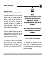
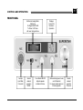
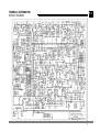
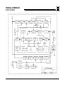
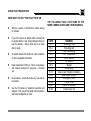
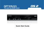
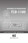
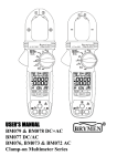
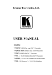
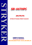
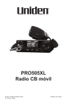
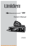
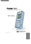
SUPERSTAR
LORD
40 Channel AM/FM Professional CB Mobile Transceiver
USER’S MANUAL
Please Read Before Use This Transceiver
PIHERNZ COMUNICACIONES. S.A.
Downloaded from www.cbradio.nl
TABLE OF CONTENTS
GENERAL INFORMATION
Introduction & Features … … … … … … … … … … … … … … … … ...........
General Notice and Certification … … … … … … … … … … … … … … … .
Documentation copy … … … … … … … … … … … … … … … … … … … … .
Page
1
2
3
SPECIFICATIONS
Transmitter / Receiver & General … … … … … … … … … … … … … … …
4
INSTALLATION
Location, wiring & Hints … … … … … … … … … … … … … … … … … … …
Mobile & Base Antenna … … … … … … … … … … … … … … … … … … …
5
6
OPERATION
Front Panel Controls & Operating … … … … … … … … … … … … … … . .
Rear Panel features … … … … … … … … … … … … … … … … … … … … . .
7
8
TECHNICAL INFORMATION
Main Circuit Diagram … … … … … … … … … … … … … … … … … … … ....
Block Diagram … … … … … … … … … … … … … … … … … … … … … … …
40CH CB Frequency Table … … … … … … … … … … … … … … … … … . .
9
10
11
USING YOUR TRANSCEIVER
Hints to Help Enjoy your CB & 10-Codes … … … … … … … … … … … .
Service & Maintenance … … … … … … … … … … … … … … … … … … …
MEMO … … … … … … … … … … … … … … … … … … … … … … … … … … .
12
13
14
INTRODUCTION
Thanks for your purchase of a Superstar
Lord professional CB radio, your mobile CB
designed for operation in 40CH class D
Citizens Band, this compact package is big
in performance.
P. 1
It is a quality piece of electronic equipment,
skillfully constructed from the latest high
quality components. The SuperStar Lord
has a built-in MCU controlled 40CH
Phase-Lock-Loop (PLL) synthesizer circuit.
The PLL circuit achieves a new technique; it
has been applied in most of delicate radio
equipment of frequency control with superior
reliability performance.
FEATURES
u
MCU controlled PLL circuit gives u
precise frequency control and stability
over all 40 Channels.
u
Precision analog meter with 4W
typical scale to max. red scale of TX u
power output level and Rx Signal
level from 1 to +30dB.
u
Real 40 steps rotary channel switch u
to ensure position of channel number
correctly for every instant selects.
u
Double Super heterodyne Receiver
system with 1st I.F. crystal filter and
2nd I.F. ceramic filters give superior u
selectivity and avoid from adjacent
channel interference.
Extremely sensitivity front-end circuit u
incorporated with (AGC) Automatic
Gain Control gives superior reception
for week and strong signals
u
Built- in (ANL) Auto Noise Limiter
reduces noise at week signal
reception.
u
Signal to Noise comparison type SQL.
Automatically compensates for signal
fading
to
eliminate
signal
“CHOPPING”
during
message u
reception.
Red LED channel read-out clearly
shows channel number in activating.
Dynamic type plug-in microphone
provides superior Tx sound quality.
External speaker output jack allowed
the receiver audio signal output to
outdoor speaker while you were out
from car compartment.
Ember Meter Backlight to show the
unit was powered ON and standby for
RX, and glows Red on TX.
External RX signal output jack
allowed connects a proper type of
analog or digital signal meter other
then the built- in one.
GENERAL INFORMATION
READ ME FIRST … … … … … … … … … … …
Our repair centers from time to time received
products, return for service, but that are
perfectly. It seems that more often than not,
the owner didn’t read the instructions, or
overlooked something. Or perhaps the
problem was merely a blown fuse that the
owner could easily have replaced.
So take an extra few minutes and read this
manual carefully, don’t rush. And be sure you
understand all the basic features of this CB
radio as well as the special ones!
!
ê
P. 2
NOTE
PIHERNZ COMUNICACIONES. S.A. IS NOT
RESPONSIBLE FOR ANY RADIO OR TV
INTERFERENCE CAUSED BY
UN-AUTHORIZED MODIFICATIONS TO THIS
EQUIPMENT.
SUCH MODIFICATIONS COULD VOID THE
USER’S AUTHORITY TO OPERATE THE
EQUIPMENT.
CERTIFICATION & DECLARATION
And before you assume your transceiver
needs repair, refer to the service and
maintenance section of this manual to see if
the problem is something you can eliminate.
This transceiver was granted for use and
selling locally, with certificate issued by the
local Telecommunication Authorization as per
attached in next page.
GENERAL INFORMATION
DOCUMENTATION
P. 3
SPECIFICATIONS
P. 4
RECEIVER
TRANSMITTER
GENERAL
FREQUENCY COVERAGE:
Full 40 CB channel (Class D) Citizen Band
Channels 26.965 to 27.405MHz.
SENSITIVITY:
FM = 0.25µV for 12dB SINAD
AM = 0.8µV for 10dB S/N
ADJACENT CHANNEL REJECTION:
Better than 60dB at 10Khz, greater than
80dB for 20Khz
INTERMEDIATE FREQUENCY:
1st I.F. = 10.695MHz. 2nd I.F. = 455KHz.
CROSS MODULATION:
More than 60dB.
AUDIO RESPONSE:
450Hz to 2500Khz, +1/-8dB from 6dB/Oct.
AUDIO OUTPUT:
Rated Max. power 5W at 8 Ohms load.
THD @10% 4W.
SQUELCH:
Adjustable from 0.3µV threshold to 1mV at
full mute.
CURRENT DRAIN:
Standby muted = 150mA.
Full Audio Output = 1.5A.
RF POWER OUTPUT:
AM/FM 4W rms
TYPE OF MODULATION:
AM = 6A3
FM = F3E
RATED MODULATION:
AM = 90% Depth.
FM = 1.5KHz Deviation Max.
SPURIOUS EMISSION:
Better Than 60dB.
MODULATION RESPONSE:
450Hz to 2500Hz, +1/-3dB from 6dB/Oct.
CURRENT DRAIN:
AM = 2.0A
FM = 1.2A
CHANNEL NUMBER:
40 Channels
FREQUENCY CONTROL SYSTEM:
MCU Controlled Phase Lock Loop (PLL)
Frequency Synthesizer.
ANTENNA IMPEDANCE:
50 Ohms
MICROPHONE CONNECTOR:
6 Pin Round.
POWER SOURCE:
13.8V DC ± 10%, Positive or Negative
Ground.
DIMENSION :
150 x 45 x 150 mm WHD
INSTALLATION
P. 5
LOCATION
WIRING FOR POWER SOURCE
HINTS:
Plan the location of the transceiver and
microphone bracket for convenience and
safety operation are the first considerations
with absolute no interferes to the driver on
driving or the passengers in the vehicle
before starting installation.
1.
Connect the supplied DC cord, with
the fused red wire to +13.8V DC source,
and the black wire to negative –13.8V DC
source in respectively, for most type of
vehicles with negative ground power
system. Thus, back wire may connect to
chaises ground of the vehicle directly.
The independent wiring system, direct
power sourcing from the battery terminal is
the proper way that strongly recommended,
this will help to avoid any interferences
from existing wiring system of the
automobile, and will minimize voltage drop
caused by other circuits in the same wiring
system, thus to provide optimum
performance of your CB radio.
In most automobiles, the transceiver is
usually mounted below the dash panel,
with microphone bracket beside it.
DO NOT! Mount the transceiver in the
path of the heater or air conditioning air
stream.
BE SURE! All cables clear of the brake,
clutch and accelerator.
When you have determined the best
location as a template to mark mounting
holes. Take care when you drill holes that
you do not drill into wiring.
2.
The positive wire should connect to
the spare fuse box terminal directly. Ensure
the space fuse box has no other
applications, and to sure with it’s current
rating not less than 10 Amp.
3.
If your spare fuse box has fully
occupied, you may add a new wiring
system with fuse holder at the wire end of
which is closer directly to the battery
positive terminal tag. Other wire end
connects to the transceiver should have a
terminal block well fixed on the vehicle
chaises.
This wiring system is for safety facility to
avoid from overloading of original wiring
system of the automobile, and to minimize
the possibility of interferences to the
electronics or electro-mechanical control
system of the automobile.
Also this allows you to keep continued
operation of your transceiver anytime
without starting the engine or to keep turn
on the ignition key.
INSTALLATION
Continuation
MOBILE ANTENNA
Mobile Antenna System is not limited to
just the antenna. The transmission line is
the important factors in the total antenna
system. Therefore, you must use the
correct type of transmission line and mount
the antenna securely in a position that will
give you optimal results.
Use Coaxial Cable with an impedance 50
ohms. Suggest type RG-58U/A for lengths
not exceeds 3 meters or RG-8U for longer
length. However, you should keep feeder
length as shorter as possible which in-order
to devoid high attenuation in RX signal
from antenna to the receiver, and TX power
lose from the transmitter to antenna.
Few General Rules should help you install
any mobile antenna properly.
1.
2.
Keep it as far as possible from the
main bulk of the vehicle.
Keep as much as possible above the
highest point of the vehicle.
P. 6
3.
4.
During operation, it must be vertical,
and rigid enough to remain vertical
when the vehicle or boat is in
motion.
Mount it as far as possible from
sources of noise, such as ignition
system, gauges, etc. keep the
antenna feeder away from these
noise sources.
Antenna Locations On Car there are 4
most popular positions shown bellows;
ROOF MOUNT
In this position the antenna radiates equally
in all directions. Since the normal 1/4
wavelength whip antenna is too long 102
inches or 2.6m for roof mounting on a
vehicle, the antenna is shortened and
loading coil is used to provide the loading
coil is used to provide the proper electrical
length, it is strongly recommended.
FRONT COWL MOUNT
The radiation pattern is slightly greater in
the direction of the fender opposition the
side on which the antenna is mounted.
REAR DECK MOUNT
The radiation pattern is strongest in
direction of the front fender opposite the
side on which the antenna is mounted. In
this position you may use a full quarter
wave whip or a shorter loaded whip.
BUMPER MOUNT
The antenna radiates in a pattern directly in
front of and to the rear of the vehicle, with
maximum radiation directly away from the
vehicle in a horizontal plane, despite its
fairly irregular pattern, a bumper mounted
full-length results. Removing the antenna is
simple and will leave no holes in the car.
BASE STATION ANTENNA
If you do decide to use your CB radio as a
base station, choose an antenna designed
to operate most efficiently as a base station
antenna. Use the 1/2 wave antenna or full
wave antenna is a high-efficiency radiator
with omni-directional characteristics. It
delivers stronger TX signal on air by
excellent matching, and with minimum lost
for RX week signal due to right resonance
produce high Q effect.
P. 7
CONTROLS AND OPERATIONS
FRONT PANEL
Multi-scale Analog Meter
Monitoring
Rx Signal 0dB +30 dB
Tx Power 1-4W max.
with over rating red zone
Accepts
6 pin Mike
Connector
Selects
desired
operation
MODE
Turns Radio ON/OFF.
Adjusts speaker
at desired Volume.
Displays
Current CH
Number in
Operation
Reduces background noise
set at threshold.
For proper adjusts when no
incoming signals.
Selects
desired
operation
Channels
P. 8
CONTROLS AND OPERATIONS
REAR PANEL
Accepts
PL-259
Antenna
Connector.
Accepts 2.5mm
Mono plug
for proper
analog or digital
Meter.
S. METER
Accepts
3.5mm MONO
Plug for External
8 ohms Speaker
Operation
EXT. S.P.
Serial No. Plate
DC 13.8V
ANT.
Power Cord with 3A fuse
Fused Red lead for Positive
Black lead for Negative
TECHNICAL INFORMATION
CIRCUIT DIAGRAM
P. 9
TECHNICAL INFORMATION
BLOCK DIAGRAM
P.10
TECHNICAL INFORMATION
P.11
40 CH CITIZENS BAND FREQUENCY TABLE
CH
01
02
03
04
05
06
07
08
09
10
11
12
13
14
15
16
17
18
19
20
FREQUENCY
26.965
26.975
26.985
27.005
27.015
27.025
27.035
27.055
27.065
27.075
27.085
27.105
27.115
27.125
27.135
27.155
27.165
27.175
27.185
27.205
Mhz
CH
21
22
23
24
25
26
27
28
29
30
31
32
33
34
35
36
37
38
39
40
FREQUENCY
26.215
26.225
26.255
27.235
27.245
27.265
27.275
27.285
27.295
27.305
27.315
27.325
27.335
27.345
27.355
27.365
27.375
27.385
27.395
27.405
Mhz
USING YOUR TRANSCEIVER
P.12
SOME HINTS TO HELP YOU ENJOY YOUR CB
THE FOLLOWING TABLE LISTS SOME OF THE
MORE COMMON CODES AND THEIR MEANINGS.
l
Wait for a pause in transmission before asking
for a break.
l
If you don’t receive an answer after a second call
to another station, sign off and allowed others to
use the channel – wait a while ask for a break
and try again.
l
Do assist callers with directions, road conditions
or other requested information.
l
Keep harassment off the air. This is unnecessary
and causes problems for everyone – including
you.
l
Be courteous – tread others the way you wish to
be treated.
l
Use the 10-Codes for standard questions and
answers. This use permits faster communication
and better intelligibility in noise.
CODE
10 -1
10 -2
10 -3
10 -4
10 -7
10 -8
10 -9
10 -10
10 -13
10 -20
10 -33
10 -36
10 -41
10 -62
MEANING
Receiving Poorly
Receiving well
Stop Transmitting
OK - Understood
Out of Service
In Service
Repeat
Standing By
Advice road / Weather Conditions
What is your location?
Emergency Traffic
Correct Time
Switch to Channel
Cannot Copy You
SERVICE & MAINTENANCE
Your Transceiver has been built in
accordance with factory’s exacting quality
control standard. However, it should be
treated with reasonable car accorded any
electronic equipment. Avoid exposing it to
severe shock, dirt or moisture.
If you run into problems with the unit, we
recommend you check the following;
IF RECEIVING TROUBLE IS
EXPERIENCED … … ..
l
l
l
l
l
l
Check the volume ON/OFF setting.
Be sure the SQL control is adjusted
properly. Is it set at deep squelch
status?
Check to see if the unit is switched
to an active channel.
Be sure the microphone plug is
securely in place.
Check for improper antenna
connection.
Check setting of mode switch in
proper operating mode.
P.13
IF TRANSMITTING TROUBLE IS
EXPERIENCED … … .
l
l
l
l
l
Check it the transmission line is
securely connected to the antenna
connector.
Check if the transmission line is
correctly installed for proper
operation.
Are
all
transmission
line
connections secure and free of
corrosion?
Make sure the PTT switch on the
microphone is fully depressed.
Check abnormal power line source,
should there has voltage drop to
cause abnormal TX output during
PTT switch was on, by observing
dimmed illumination system may
occurs.
IF THE TRANSCEIVER IS
COMPLETELY INOPERATIVE … ….
Check the power cable and inline fuse. If
the fuse is blown replace it only with an
identical rating 2A fuse.
If above checks don’t solve the trouble,
DO NOT attempt repairs or adjustments
yourself. The unit should be service only
by a qualified radio technician, or return
the radio to its services center.
WARNING!
DO NOT OPEN THE TRANSCEIVER TO
MAKE ANY INTERNAL ADJUSTMENTS.
ANY INTERNAL ADJUSTMENTS CAN
BE MADE ONLY BY, OR UNDER THE
DIRECT SUPERVISION OF A PRESON
WITH A RECOGNIZED QUALIFICATION.
INTERNAL
ADJUSTMENTS
OR
MODIFICATIONS CAN LEAD TO
ILLEGAL OPERATION AS UN–KNOWN
INTERFERENCE
SIGNALS
MAY
DISTURB OTHER COMMUNICATIONS.
l
l
TO BE SAFE AND SURE
You should never open the case
of your transceiver.
Never change or replace
anything in your transceiver.
MEMO
Thank You For Purchasing
SS-LORD Professional CB Mobile Transceiver
PIHERNZ
COMUNICACIONES. S.A.
Elpse,32
Tels. 93 334 88 00 – 449 10 95
Fax. 93 440 74 63 – 334 04 09
08905 L’HOSPITALET de LLOBREGAT
BARCELONA – ESPANA