1
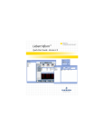
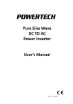
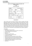
“C” type Generator End
User’s Manual
Addendum
For 15,17.5, 20 and
25kW gensets with “C”
in third position in
Serial Number
Power Technology Southeast, Inc.
634 SR 44 W.
Leesburg, FL 34748
800-760-0027
Fax: 352-787-5545
www.powertech-gen.com
1
Please read this manual carefully prior to installing and operating this generator.
If you have any questions please feel free to contact us at 800-760-0027 or via our
website at www.powertech-gen.com
General Technical Data of the Generators
•
Synchronous brushless generator, single phase
•
Rated 22kW and 25kW,120/240V, 250/125Amps
•
4-pole, 60Hz,1800RPM, PF=1.0, Continuous Duty
•
Temp rise 105°C / 50°C ambient temperature
•
Suitable for operation with VR3.1
•
Insulation Class H
•
SAE 4, SAE 7 ½
•
Single bearing
The use of any spare parts that are not genuine or not expressly authorized shall free
Power Technology Southeast, Inc. from any warranty liability and any responsibility
concerning conformity to regulations and relevant consequences.
Installation, after-sales modifications and maintenance must be carried out by
adequately trained staff.
2
TABLE OF CONTENTS
RULES FOR SAFE OPERATION ........................................................................................................................ 4
RECEIVING THE GENERATOR......................................................................................................................... 5
STORING THE GENERATOR ........................................................................................................................... 5
INSTALLATION ............................................................................................................................................... 6
LIFTING THE GENERATOR.......................................................................................................................... 6
LOCATION/ENVIRONMENT ....................................................................................................................... 6
MOUNTING GENERATOR TO ENGINE ....................................................................................................... 6
EARTH/GROUND THE GENERATOR ........................................................................................................... 6
OPERATION ................................................................................................................................................... 7
BEFORE STARTUP ...................................................................................................................................... 7
START-UP .................................................................................................................................................. 7
SHUTDOWN .............................................................................................................................................. 7
MAINTENANCE .............................................................................................................................................. 8
GENERAL MAINTENANCE .......................................................................................................................... 8
INSULATION RESISTANCE TEST ................................................................................................................. 8
DRYING OUT THE GENERATOR WINDINGS ............................................................................................... 8
TROUBLESHOOTING ...................................................................................................................................... 9
MECHANICAL ISSUES................................................................................................................................. 9
ELECTRICAL ISSUES.................................................................................................................................... 9
FLASHING THE FIELD ............................................................................................................................... 11
REPLACING THE RECTIFIED ASSEMBLY ................................................................................................... 11
AVR ADJUSTMENTS ................................................................................................................................. 11
RESISTANCE VALUES FOR WINDINGS ..................................................................................................... 11
APPENDIX A – EXPLODED VIEW .................................................................................................................. 12
APPENDIX B – SPARE PARTS LIST ................................................................................................................ 13
APPENDIX C – Wiring diagram for Single Phase Generator (4 LEADS)........................................................ 14
3
RULES FOR SAFE OPERATION
!
ALWAYS check the machine for loosened
threads, bolts, or other parts before starting.
NEVER operate the generator in an
explosive atmosphere or where fire could
result.
CAUTION!
FAILURE TO FOLLOW INSTRUCTIONS
IN THIS MANUAL MAY LEAD TO
SERIOUS INJURY OR EVEN DEATH!
THIS EQUIPMENT IS TO BE OPERATED
BY
TRAINED
AND
QUALIFIED
PERSONNEL ONLY! THIS EQUIPMENT IS
FOR INDUSTRIAL USE ONLY.
The following safety guidelines should
always be used when operating,
servicing, or maintain the generator end.
DO NOT operate or service this equipment
before reading this entire manual. This
equipment should not be operated by
persons under 18 years of age.
ALWAYS make sure generator installation
is in accordance with electrical codes for
your location.
ALWAYS have a qualified electrician
perform the generator wiring installation.
NEVER operate this equipment without
proper protective clothing, shatterproof
glasses, steel toed boots and other
protective devices.
NEVER operate this equipment when not
feeling well due to fatigue, illness or taking
medicine.
NEVER operate this equipment under the
influence of drugs or alcohol.
NEVER use accessories or attachments,
which are not recommended by your local
distributor or original manufacturer for this
equipment. Manufacture does not assume
responsibility for any accident due to
equipment modifications.
ALWAYS allow the generator to cool before
performing service and maintenance
functions. Contact with HOT components
can cause serious burns.
NEVER operate the generator in any
enclosed or narrow area where free flow of
the air is restricted. If the air flow is
restricted it will cause serious damage to
the generator or engine and may cause
injury to people. The generator engine gives
off DEADLY carbon monoxide gas.
ALWAYS make sure generator is properly
grounded.
DO NOT place hands or fingers inside the
generator when engine is running
(generator is rotating).
NEVER allow power cables or cords to lay
in water or any other liquid.
The electrical voltage required to operate
the generator can cause severe injury or
even death through physical contact with
live circuits. Turn all circuit breakers OFF
before performing maintenance on the
generator.
ALWAYS make sure that electrical circuits
are properly grounded per the National
Electrical Code (NEC) and local codes
before operating generator. Severe injury or
death by electrocution can result from
operating an ungrounded generator. If the
unit is sold internationally (outside USA),
please make sure that grounding is done
according to the local electrical code.
ALWAYS store equipment properly when
not being used. Equipment should be stored
in a clean and dry location.
4
!
STORING THE GENERATOR
DANGER!
HAZARDOUS VOLTAGE. Voltage or
current hazard sufficient to cause shock,
burn, or death. Disconnect and loackout
power before servicing.
NEVER touch output terminals during
operation. This is extremely dangerous.
ALWAYS stop the machine and place the
circuit breaker in the “OFF” position when
contact with the output terminals is required.
There exists the possibility of electrocution,
electrical shock or burn, which can cause
severe bodily harm or even death!
Back feed to a utility system can cause
electrocution and or property damage. DO
NOT connect to any building's electrical
system except through an approved device
or after building main switch is opened.
ALWAYS have a licensed electrician
perform the installation.
If the generator is not immediately used, it
should be stored indoors in a clean and dry
environment.
If the generator is stored for an extended
period of time, it should be cleaned and
tested before operation. Also, check all bolts
for tightness and examine the insulation on
lead wires for chafing.
NOTE: Wet windings should be
thoroughly dried out before operation
otherwise serious damage to the
generator can result. Please see the
Maintenance section of the User Manual
on how to how to dry out the generator
windings.
RECEIVING THE GENERATOR
Once the generator is received you should
first examine it carefully for any damages
during shipping and for missing parts. If
there is shipping damage, then please make
note of the damage with the carrier, and
contact Power Technology Southeast, Inc.
immediately.
NOTE: Please note any damage with the
carrier and be sure to note this damage
on the Bill of Lading document. Take
digital photos when available and be
sure to properly document the damage.
5
INSTALLATION
Check the generator thoroughly before
starting installation. Make sure there is no
damage during shipment or during storage.
Perform the Insulation Resistance Test and
dry out the generator windings if necessary.
Check Maintenance Section of this Manual
for additional instructions.
LIFTING THE GENERATOR
!
WARNING!
THE GENERATOR LIFTING EYE IS
DESIGNED
FOR
LIFTING
THE
GENERATOR
ONLY. IT
IS
NOT
DESIGNED TO USE TO LIFT THE
GENERATOR AND ENGINE (GENERATOR SET).
USING EQUIPMENT WITHOUT PROPER
LOAD BEARING CAPACITY CAN CAUSE
SEVERE INJURY AND DAMAGE.
Do not lift single bearing generators without
the rotor anchor bar securely fixed. Remove
the rotor anchor bar only when attaching the
generator to the engine. Lift the generator
horizontally in order to prevent the rotor
from slipping out.
LOCATION/ENVIRONMENT
Installation of the generator to the engine
must be done in a location that is protected
from moisture, dust, dirt, and harmful fumes.
Generator intake and outlet air passages
need to be unobstructed during generator
operation. Please do not mount any
obstructions that would restrict the airflow.
The generator needs sufficient air
circulation in order to provide proper
cooling. Make sure that hot air from radiator
or engine does not pass through the
generator.
Make sure the mounting surface (generator
set base) has sufficient strength, rigidity,
and uses the proper anti-vibration mounts in
order to keep vibration and noise to a
minimum.
MOUNTING GENERATOR TO ENGINE
Generator is mounted to the engine by the
use of the generator coupling disc which fits
perfectly into the recess on the engine
flywheel.
Holes on the coupling disc correspond to
threaded holes on the engine’s flywheel.
The coupling disc will mate with the prime
mover’s flywheel so that concentricity is
obtained.
Coupling to Engine:
1. Make sure that the generator and
engine are level.
2. Carefully pull out the main rotor
assembly from the generator housing.
Be careful not to damage the copper
stator windings.
3. Make sure the generator coupling disc is
flat against the engine flywheel and fits
perfectly into the recess on the engine
flywheel. Use appropriate bolts and
hardened washers to mount the
coupling disc to the engine flywheel.
Tighten with calibrated torque wrench.
Split type lock washers should NOT be
used due to possible damage to
coupling disc.
4. Mount generator housing over rotor and
mount to engine housing. Check that the
exciter rotor and exciter stator are
aligned.
5. Mount the generator SAE housing to the
engine housing. If bolted properly there
should be no further alignment
necessary.
EARTH/GROUND THE GENERATOR
The generator housing has to be connected
to ground. If flexible anti-vibration mounts
are used, then an earth conductor should be
6
connected in parallel to the base for proper
grounding. Generator has an “earthing” bolt
on the housing.
!
WARNING!
MAKE
SURE
THAT
GENERATOR
EARTHING/GROUNDING
IS
DONE
PROPERLY. NOT DOING SO CAN
CAUSE SHOCK AND EVEN DEATH.
OPERATION
BEFORE STARTUP
The following steps are recommended prior
to starting the generator for the first time:
1. Make sure generator and engine are
level and bolted securely on a base.
2. Check visually for any foreign materials.
3. Make sure all nuts and bolts are
tightened properly.
4. Check all connections against the wiring
diagram – especially the generator lead
wires. Make sure connections are tight
and properly insulated. Vibration can
cause connections to loosen, disconnect
or rotate causing short circuits.
5. Make sure generator is grounded
correctly using generator grounding bolt
located on the housing.
6. Make sure fan screen is assembled on
the bell housing.
START-UP
1. Make sure generator is in no-load
condition - disconnect generator output
from load. This can be done by
switching the circuit breaker in the OFF
position or not connecting a load to the
gen set terminals.
2. Remove field excitation wires (F-) and
(F+) from AVR. (See the Automatic
Voltage Regulator User Manual).
3. Check that that all engine start-up
procedures have been followed.
4. Start engine and adjust engine speed
initially between 60Hz to 62Hz (for 60Hz
rated generator). Reference engine
manual for how to adjust speed.
5. Using properly rated voltmeter check
line-to-line and line-to-neutral residual
voltages
on
generator
terminal
connections. Residual voltages will be
much smaller than rated generator
voltages. If voltages are unbalanced or
not according to expected ratios, shut
down the engine and re-check the
wiring.
6. If voltages are correct (balanced), shut
down the engine and connect exciter
field wires (F-) and (F+) to AVR. (See
the Automatic Voltage Regulator User
Manual).
7. Start the engine again. Have voltmeter
hooked up to generator terminal board
and adjust voltage to the rated value
(120V/240V) by rotating the AVR
voltage adjust screw. (See the
Automatic Voltage Regulator User
Manual).
8. Once AVR is adjusted, check again all
line-to-line and line-to-neutral voltages
on generator terminal connections for
proper voltage levels.
9. If voltage levels in Step 8 are correct,
then shut down the engine, and close
the main circuit breaker to the load.
Start up engine with load applied.
10. Check generator speed (frequency)
under load. Adjust as necessary.
11. It is recommended to apply different
load levels for a few minutes (25% load,
50% load, 75% load, full load, and 110%
load) to the generator and test voltage
levels for proper adjustment and
function.
SHUTDOWN
Shutdown varies based on the engine used.
Please reference the engine User Manual
for proper shut down procedures.
7
MAINTENANCE
GENERAL MAINTENANCE
Check generator windings for buildup of
dirt, oil, or any other substances. If
found, please remove rotor and clean.
Make sure the generator windings are
dry before assembling.
Check generator intake and exhaust
venting openings (bearing cover and
bell housing screen) to ensure airflow is
not obstructed. Clean as needed.
Periodically check bearings for unusual
operation. Unusual operation is defined
by excessive vibrations, unusual noise,
grease leaking, etc. Replace bearings if
unusual operation determined.
Before operation check the resistance of
the stator winding by performing the
Insulation Resistance Test. The reading
should be greater than 2 MΩ otherwise
drying out the windings will be
necessary.
DRYING OUT THE GENERATOR
WINDINGS
One or more of the following methods can
be used to dry out the windings.
Push hot air through the generator using
heaters and blowers. Make sure the air
can flow freely through the generator.
Also, be careful not to overheat the
windings which could cause permanent
damage.
Run the generator set unexcited by
disconnecting the AVR terminals (open
circuit) for 15 minutes.
Oven dry the generator for up to 3 hours
at 60°C-80°C temperature. Make sure to
remove AVR during oven drying.
Once the Insulation Resistance is raised to
a level of greater than 2 MΩ then the
generator can be put into service.
INSULATION RESISTANCE TEST
1. Disconnect all electronic components,
AVR, etc.
2. Short out the diodes on the rotating
diode assembly.
3. Use a MegOhmMeter or Insulation
Multimeter rated at least 500V and
connect between an output lead
terminal and ground, and later
disconnect the lead wires from the
terminal board and measure the
resistance between lead wires and
ground.
4. Measured value of insulation resistance
for all windings to ground and between
phases. Measured values should be
greater than 2 MΩ. If not, then dry out
the generator windings.
8
TROUBLESHOOTING
MECHANICAL ISSUES
SYMPTOM
Generator
Overheating
Excessive
Vibration / Noise
CAUSE
SOLUTION
Air vents obstructed, preventing
normal air flow required for
cooling
Check vents at rear bearing cover and fan intake
air vent and make sure obstructions are removed.
Load exceeds generator rated
load
Reduce the load on the generator to equal or
below rated load listed on generator name plate.
High ambient temperature
Improve airflow to generator. Make sure that hot
air is not recycled from generator or engine.
High altitude
Altitude reduces the rating and affects the cooling
of generator. Reduce load of generator until
overheating stops.
Misalignment of coupling between
generator and engine.
Realign and tighten connection between coupling
disc and engine flywheel, and generator housing
and engine housing. Make sure correct grade
bolts are used and are tightened to appropriate
torque level using calibrated torque wrench.
Faulty or damaged bearing
Replace bearing.
ELECTRICAL ISSUES
SYMPTOM
CAUSE
Exciter stator output voltage too
low to start AVR
Generator will
not excite, no
voltage
Loss of residual magnetism
Faulty AVR
Faulty diodes or rectifier assembly
Disconnected or shorted exciter
rotor or main rotor lead wires
Damaged or burnt exciter
rotor/stator, stator or rotor
windings
Check engine speed (RPM)
No load voltage
too low
Incorrect or faulty wiring.
AVR not adjusted correctly
SOLUTION
First try increasing the engine speed to 110% of
rated RPM for a few seconds to see if excitation
is achieved. If this does not work then Flash the
Field to restore residual magnetism.
Flash the Field to restore the residual magnetism.
Adjust or replace AVR. See AVR Manual.
Check diodes first. Then replace the faulty
rectifier assembly.
Check lead wires for short or disconnection and
repair.
Check windings (visual check, smell check),
measure resistances and compare with the rated
values. Replace faulty parts.
Increase speed on engine slowly to increase
voltage. Do not increase speed over 110% of
rated RPM.
Check wiring against the Generator Wiring
Diagrams in the Appendix. Check wires for short
and open connections.
Calibrate AVR by adjusting the Voltage screw /
potentiometer. See AVR Manual.
9
Damaged or burnt exciter
rotor/stator, stator or rotor
windings
Check windings (visual check, smell check),
measure resistances and compare with the rated
values. Replace faulty parts.
ELECTRICAL ISSUES (continued)
SYMPTOM
CAUSE
AVR not adjusted correctly
Check engine speed (RPM)
No load voltage
too high
Voltage below
nominal, under load
Check wiring against the Generator Wiring
Diagrams in the Appendix. Check wires for
short and open connections.
Faulty AVR
Adjust or replace AVR. See AVR Manual.
AVR not adjusted correctly
Calibrate AVR by adjusting the Voltage screw /
potentiometer. See AVR Manual.
Current too high (excessive load)
or speed below nominal
Reduce load and make sure current does not
exceed rated current.
Faulty AVR
Adjust or replace AVR. See AVR Manual.
AVR not adjusted correctly
Faulty AVR
Non-uniform rotation of engine
Unstable voltage
Calibrate AVR by adjusting the Voltage screw /
potentiometer. See AVR Manual.
Decrease speed until rated voltage is achieved.
Rated voltage is listed on generator name
plate.
Incorrect or faulty wiring
Faulty diodes
Voltage above
nominal, under load
SOLUTION
Misalignment of generator and
engine.
AVR is unstable
Check the diodes. Replace the rectifier
assembly.
Calibrate AVR by adjusting the Voltage screw /
potentiometer. See AVR Manual.
Adjust or replace AVR. See AVR Manual.
Check for uniform rotation of engine. Engine
could be at fault. Check with engine User
Manual or manufacturer for further
troubleshooting.
Check for mounting of rotor and stator on
engine. Check that air gap is even on all sides.
Re-mount rotor and generator housing on
engine.
Calibrate AVR by adjusting the Stability control
screw (potentiometer) on AVR. See AVR
Manual.
10
SERVICE
FLASHING THE FIELD
8. Put back on the rear bearing cover.
Residual magnetism of the exciter stator
may be lost or weakened if the generator is
not operated for long periods of time, during
long periods of transport, or due to other
situations.
AVR ADJUSTMENTS
While flashing the field, the generator
MUST BE out of operation.
Steps to flashing the field
1. Make sure the generator is not in
operation (not rotating) and all terminals
disconnected.
2. Disconnect exciter stator leads F+ and
F- from the AVR.
3. Connect 12V DC battery to terminals F+
and F-, making sure that the (+) pole of
the 12V DC battery is connected to F+
and (-) pole connected to F-.
4. Connect battery leads for approximately
3 to 5 seconds and then disconnect
from F+ and F-.
5. Reconnect the F+ and F- to AVR.
6. Start the engine and run at rated RPM,
with no load and check voltages.
7. Re-flash the field if generator voltage
does not build up to rated values.
REPLACING THE RECTIFIED ASSEMBLY
1. Disconnect the exciter stator leads F+
and F- from AVR.
2. Remove the rear bearing cover.
3. Remove the bearing from the shaft.
4. Disconnect all the wires to the rectifier
assembly.
5. Remove rectifier assembly.
6. Replace with new or repaired rectifier
assembly. Lock the screws with thread
adhesive and reconnect all the wires.
7. Mount the bearing on the shaft.
Adjustments on the AVR include screws /
potentiometers that can adjust voltage and
stability.
Voltage Adjustment - Change the output
voltage by adjusting the Voltage
potentiometer screw on the AVR. Make
sure generator is rotating at rated RPM.
Turn clockwise to increase voltage and
counter clockwise to reduce voltage.
See AVR manual for additional
instructions.
Stability Adjustment – Change the
stability of the generator by adjusting the
Stability potentiometer screw on the
AVR. Turn clockwise to increase
stability and counter clockwise to reduce
stability. See AVR manual for additional
instructions.
RESISTANCE VALUES FOR WINDINGS
Rating
(kW)
20
Stator
U1-U2
(mΩ)
60
Rotor
(Ω)
1.03
Exciter Exciter
Stator
Rotor
(Ω)
(mΩ)
18
126
22
60
0.9
18
130
25
47
1.0
18
130
11
1CB Series User Manual
APPENDIX A – EXPLODED VIEW
16
17
19
18
20
10
4
3
9
8
7
11
1
12
13
14
5
2
6
15
Reference
Number
1
2
3
4
5
6
7
8
9
10
Part Name
Bearing cover
Exciter stator
Exciter stator lead wires
Bolts for exciter stator
Generator housing
Generator mounting feet
Stator
Terminal lead wires (4 leads)
Bearing
Rectifier assembly
Reference
Number
11
12
13
14
15
16
17
18
19
20
Part Name
Exciter rotor
Main rotor
Fan
Coupling disc
Bolts for coupling disc
Automatic Voltage Regulator (AVR)
Terminal board
Base for AVR and Terminal board
Control box cover
Control box
12
1CB Series User Manual
APPENDIX B – SPARE PARTS LIST
Reference
Number
1
2
3
4
5
6
7
8
9
10
11
12
13
14
15
16
17
18
19
20
Part Name
Bearing cover
Exciter stator
Exciter stator lead wires
Bolts for exciter stator
Generator housing
Generator mounting feet
Stator
Terminal lead wires (4 – 12 leads)
Bearing
Rectifier assembly
Exciter rotor
Main rotor
Fan
Coupling disc
Bolts for coupling disc
Automatic Voltage Regulator
Terminal board
Base for AVR and Terminal board
Control box
Control box cover
Part Number
*1CB-xx-001-00
*1CB-xx-002-00
N/A
N/A
N/A
N/A
N/A
N/A
*1CB-xx-009-00
*1CB-xx-010-00
*1CB-xx-011-00
*1CB-xx-012-00
*1CB-xx-013-00
N/A
N/A
VR3.1-00UL
1CB-TB-00UL
N/A
*1CB-xx-019-00
N/A
* “-xx-“ –Insert kW rating for generator to complete Part Number. For example, Exciter Stator for
25kW generator is 1CB-25-002-00.
13
1CB Series User Manual
APPENDIX C – Wiring diagram for Single Phase Generator
14
1CB Series User Manual
15