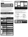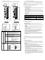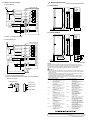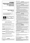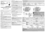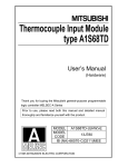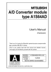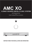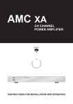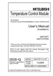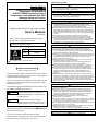
1
[DESIGN PRECAUTIONS]
DANGER
A1S62TCRT-S2 Heating-Cooling
Temperature Control Module
A1S62TCRTBW-S2 Heating-Cooling
Temperature Control Module with Wire
Breakage Detection Function
z Configure a safety circuit external to the programmable controller, so that the
entire system operates safety even if there is an external power error or if
the programmable controller is malfunctioning.
CAUTION
z Do not bundle, or near the control cables and communication cables with the
main circuit and power cables. Keep them at least 100mm (3.94inch) away
from such cables. Noise may cause malfunction.
[INSTALLATION PRECAUTIONS]
CAUTION
Mitsubishi General-Purpose Programmable Controller
User’s Manual
(Hardware)
Thank you for purchasing the Mitsubishi general-purpose
programmable controller MELSEC-A series.
Prior to use, please read this manual thoroughly and
familiarize yourself with the product.
Type
A1S62TCRT-U-HW-E
Type
13JL33
Code
IB(NA)-66801-E(0804)MEE
C 1997 MITSUBISHI ELECTRIC CORPORATION
z SAFETY PRECAUTIONS z
(Read these precautions before using.)
When using Mitsubishi equipment, thoroughly read this manual and the
associated manuals introduced in the manual. Also, pay careful attention
to safety and handle the module properly.
These precautions apply only to Mitsubishi equipment. Refer to the CPU
module user's manual for a description of the programmable controller
system safety precautions.
These zSAFETY PRECAUTIONSz classify the safety precautions into
two categories: "DANGER" and "CAUTION".
DANGER Procedures which may lead to a dangerous
condition and cause death or serious injury if not
carried out properly.
CAUTION Procedures which may lead to a dangerous
condition and cause superficial to medium injury, or
physical damage only, if not carried out properly.
Depending on circumstances, procedures indicated by
CAUTION may
also be linked to serious results.
In any case, it is important to follow the directions for usage.
Store this manual in a safe place so that you can take it out and read it
whenever necessary. Always forward it to the end user.
z Use the programmable controller in the environment given in the general
specifications of the this manual. Using the programmable controller
outside the range of the general specifications may result in electric shock,
fire or malfunctioning. or may damage or degrade the module.
z Insert the tabs at the bottom of the module into the mounting holes in the
base module before installing the module, and after tightening the module
fixing screws with specified torque. If the connector is not property installed
and tightened. If may result in malfunctioning, failure or cause the module to
lam out.
z Do not directly touch the module’s conductive parts or electronic
components. Doing so could cause malfunction or failure in the module.
z Insert the wire breakage detection connector installation screw into the
mounting holes in the module, and after tightening the connector installation
screw with specified toque. If the connector is not property installed and
tightened, it may result in error detetion of wire breakage.
[WIRING PRECAUTIONS]
CAUTION
z Be sure to ground the shield wire with a special programmable controller
ground of Type III or above. Not doing so could result in malfunction.
z Use applicable solderless terminals and tighten with the specified torque.
If any solderless spade terminal is used, it may be disconnected when the
terminal screw comes loose, resulting in failure.
z When wiring in the programmable controller, be sure that it is done correctly
by checking the product's rated voltage and the terminal layout. Connecting
a power supply that is different from the rating or incorrectly wiring the
product could result in fire or failure.
z Tighten the terminal screws with specified torque. Loose terminal screws
may cause a short circuit, fire, or malfunction.
Tightening the terminal screws too far may cause damage to the screw
and/or the module, resulting in short circuit, or malfunctions.
z Be sure that cuttings, wire chips, or other foreign matter do not enter the
module. Foreign matter may start a fire or cause failure or malfunctions.
z Be sure to fix communication cables and power cables leading from the
module by placing them in the duct or clamping them. Cables not placed in
the duct or without clamping may hang or shift, allowing them to be
accidentally pulled, which may result in a module malfunction and cable
damage.
z When detaching the communication cable from the module, do not pull the
cable portion. For cables with connectors, hold the connector at the junction
to the module, then detach it. For cables without connectors, first loosen the
screw at the junction, then detach to the cable. Pulling the cable portion
while it is connected to the module may cause a malfunction or damage to
the module and cable.
[STARTING AND MAINTENANCE PRECAUTIONS]
CAUTION
z Do not touch the terminal while the power is on.
It may cause malfunction.
z Make sure to switch all phases of the external power supply off before
cleaning or re-tightening the terminal screws. If you do not switch off the
external power supply, it will cause failure or malfunction of the module.
Tightening the screw too far may cause damage to the screw and/or the
module, resulting in fallout , short circuit , or malfunctions.
z Never disassemble or modify the module. This may cause failure,
malfunctioning, injury and/or fire.
z Make sure to switch all phases of the external power supply off before
mounting or removing the module. If you do not switch off the external
power supply, it will cause failure or malfunction of the module.
z Do not install/remove the terminal block more than 50 times after the first use
of the product. (IEC 61131-2 compliant)
z Always make sure to touch the grounded metal to discharge the electricity
charged in the body,etc., before touching the module.
Failure to do so may cause a failure or malfunctions of the module.
[DISPOSAL PRECAUTION]
CAUTION
z When disposing of this product, handle it as industrial waste.
Table 2.1 A1S62TC performance specification (continued)
About This Manual
The following product manuals are available. Please use this table as a
reference to request the appropriate manual as necessary.
Item
Detailed manual
Manual name
Manual No.
(Model Code)
A1S62TCRT-S2 Heating-Cooling Temperature Control Module
A1S62TCRTBW-S2 Heating-Cooling Temperature Control Module
with Wire Breakage Detection Function User's Manual
SH-3644
(13JL36)
Heater wire
breakage
disconnection
specification
Current sensor
Input method
Please read A1S62TCRT-S2 Heating-Cooling Temperature Control Module
A1S62TCRTBW-S2 Heating-Cooling Temperature Control Module with Wire
Breakage Detection Function User's Manual (Detailed edition) when using this unit.
1. General Description
This user's manual describes the specification, name of each part, wiring, etc.
of the A1S62TCRT-S2 Heating-Cooling Temperature Control Module
(Hereafter abbreviated as A1S62TCRT-S2 ) A1S62TCRTBW-S2
Heating-Cooling Temperature Control Module with Wire Breakage Detection
Function (Hereafter abbreviated as A1S62TCRTBW-S2) A1S62TCRT-S2
and A1S62TCRTBW-S2 abbreviated as A1S62TC.
After unpacking, confirm that there is the following products.
Item
A1S62TCRT-S2
A1S62TCRTBW-S2
A1S62TCRT-S2
Main body
1
-
A1S62TCRTBW-S2
Main body
1
Number of alert
delays
Occupied input points
Connection terminal
Supported cable size
Supported solder-less terminal
Internal consumed current (5VDC)
Weight
The A1S62TC performance specification is indicated in Table 2.1.
Table 2.1 A1S62TC performance specification
Item
Specification
A1S62TCRT-S2
A1S62TCRTBW-S2
Transistor output
2-channel/module
Control output
Temperature input points
Supported platinum
Refer to Table 2.2.
temperature-measuring resistor
Ambient temperature:
Full scale ( 0.3%) 1 digit*1
Specification 23
5
accuracy
Ambient temperature: 0
Full scale ( 0.7%) 1 digit*1
to 55
0.5s/2-channel (It is not connected with the
Sampling period
number of channels used)
Heating control output period
1 to 100s
Cooling control output period
Sensor current
0.25mA
Allowable input wire resistor effects
Less than 20Ω
Input filter
0 to 100s (0: input filter off)
Sensor compensation value setting
-50.00 to 50.00%
Operation when sensor input is
Upscale processing
disconnected
Temperature control method
PID on/off pulse
PID constant setting
Auto-tuning setting is possible
Heating proportional band
(Ph)
PID
0.1 to 1000.0%
constant Cooling proportional band
range
(Pc)
Integral time (I)
1 to 3600s
Derivative time (D)
0 to 3600s (0: PI control)
Within the temperature range set by the
Set value setting range
platinum temperature-measuring resistor to
be used.
Cooling method setting
Air cooling/water cooling
Output signal
ON/OFF pulse
Rated load voltage
10.2 to 30.0VDC (peak voltage : 30.0VDC)
0.1A/1 point
Maximum load current
0.4A/common
Maximum inrush current
0.4A 10ms
Transistor
Maximum current when
Less than 0.1mA
output
OFF
Maximum voltage drop
1.0VDC (TYP) 0.1A
when ON
2.5VDC (MAX) 0.1A
OFF ON: Less than 2ms
Response time
ON OFF: Less than 2ms (resistor load)
Between the input and grounding:
transformer insulation
Insulation method
Between the input and channel:
transformer insulation
3 to 255
32 points (I/O allocation: special 32 points)
20 points terminal block
0.75 to 1.5 mm2
R1.25-3, 1.25-YS3, RAV1.25-3, V1.25-YS3A
0.19A
0.28A
0.25kg [0.55lb]
0.28kg [0.62lb]
For the noise resistance, dielectric withstand voltage, and insulation resistance
for the programmable controller system which uses this module, refer to the
power module specification found in the CPU Module User’s Manual.
*1: “ 1 digit” error depends on the input range.
For setting unit of 1 , 1
For setting unit of 0.1 , 0.1
*2: Only the URD International, Ltd. current sensor can be used.
Sales channels for current sensors manufactures by URD International
Ltd. are listed as follows:
U.S.A.
2. Performance Specification
Specification
A1S62TCRT-S2
A1S62TCRTBW-S2
URD manufactured
current sensor*2
CTL-12-S36-8
(0.0 to 100.0A)
CTL-6-P-H
(0.00 to 20.00A)
(Former model,
CTL-6-P is also
applicable.)
Multiplex method A/D
conversion
BRAZIL
Julia Industries Inc.
Tel:949-831-0111
Ananda Industial Ltda.
Tel:011-5584-0959
UNITED
KINGDOM Omni Components
Tel:024-7622-5757
GERMANY Allied Electronics GmbH
Tel:0221-497-3084
FRANCE Diltronic S.A.
Tel:01-34-51-33-00
ITALY
ELNET s.n.c.
Tel:041-50-19-939
KOREA
Joyang Trading Co.
Tel:02-521-2294
Sewon Tech Co.,Ltd.
Tel:02-868-9355/9356
Keum Ho Corporation
Tel:51-319-4155/4156
HONG-KONG Weltronics Components Ltd.
Tel:2410-0623
TAIWAN
Tope Co.,Ltd.
Tel:886-2-8228-0658
INDIA
AmtechElectronics PVT.Ltd.
Tel:02712-25324
Table 2.2 The types of supported platinum temperature-measuring
resistor and the measured temperature range
Platinum
temperature-mea
Measured
suring resistor temperature range
-200.0 to 600.0
Pt 100
-200.0 to 200.0
-200.0 to 500.0
JPt100
-200.0 to 200.0
Data
resolution
0.1
0.1
°F
Measured
temperature range
-300 to 1100
-300.0 to 300.0
-300 to 900
-300.0 to 300.0
For the general specifications, refer to the User’s Manual for the
programmable controller CPU used.
Data
resolution
1
0.1
1
0.1
3. Name of Each Part
4. Loading and Installation
A1S62TCRT-S2
1)
CH1
CH2
RUN
H OUT
C OUT
ALM
H OUT
C OUT
ALM
CH1
1)
CH2
1
L1H
L2H
L1C
3
L2H
5
L2C
;
A1
4
6
NC
NC
7
B1
B1
8
NC
NC
9
b1
b1
10
NC
NC
11
NC
NC
12
NC
NC
13
NC
NC
14
NC
NC
15
A2
A2
16
NC
NC
17
B2
B2
18
NC
NC
19
b2
H OUT
C OUT
ALM
BR.W
H OUT
C OUT
ALM
BR.W
RUN
1
L1H
2
L1C
L2C
+ A1
Precautions when handling the A1S62TC and installation environment are
explained.
For details of implementing and setting up this unit, please refer to the User’s
Manual for the programmable controller CPU used.
A1S62TCRTBW-S2
b2
20
2
3
4
5
6
7
8
9
10
11
12
13
14
15
16
17
18
19
20
4.1 Handling Instructions
1) The module case is made of plastic. Be sure not to drop it or subject it
to strong vibration.
2) Do not remove the module printed circuit boards from the case.
It may cause trouble.
3) When connecting the wiring, do not allow wire cuttings or other foreign
matter to enter from the top of the module. Remove any foreign matter
from the module.
4) Tighten the module installation screws within the following tightening
torque range.
Screw position
Module installation screw (M4 screw)
Terminal block terminal screw (M3.5 screw)
Terminal block installation screw (M4 screw)
Wire breakage detection connector installation
screw (M2.6 screws)*
Cable fixing screw (M2 screws)*
Tightening torque range
78 to 118N•cm
59 to 88N•
78 to 118N•cm
15 to 30N•cm
11 to 14N•cm
*:Use only for A1S62TCRTBW-S2 .
2)
A1S62TCRT-S2
A1S62TCRTBW-S2
A1S62TCRT-S2 LED
A1S62TCRTBW-S2 LED
A1S62TCRT-S2
A1S62TCRTBW-S2
CH1
CH2
Number
1)
H OUT
C OUT
ALM
H OUT
C OUT
ALM
RUN
CH2
Name
LED
RUN
OUT
ALM
BR.W
2)
CH1
Wire breakage
detection
connector
RUN
H OUT
C OUT
ALM
BR.W
H OUT
C OUT
ALM
BR.W
Description
A1S62TC operation status display
ON: Normal operation in progress
Flashing (2 sec. ON/2 sec. OFF): Write data error
Flashing (1 sec. ON/1 sec. OFF): Hardware error
OFF: 5V power shutoff, Watchdog timer error
Transistor output status display
ON: Transistor output ON
OFF: Transistor output OFF
Alert alarm status display
ON: Alert alarm is ON.
Flashing: The measured temperature range is
exceeded.
The platinum temperature-measuring
resistor is not connected.
The platinum temperature-measuring
resistor cable is disconnected.
OFF: Alert alarm is OFF
Heater wire breakage detection status display
ON: Heater wire breakage is detected.
OFF: Heater wire breakage is not detected.
Connector for current sensor
Wire breakage detection
connector installation screw
BW1(For CH1)
BW2(For CH2)
Cable fixing screw
NC(Unusable)
4.2 Installations Enviroment
Never install the AnS series programmable controller system in the
following environments:
1) Locations where the ambient temperature is outside the range of 0 to
55 .
2) Locations where the ambient humidity is outside the range of 10 to
90%RH.
3) Locations where dew condensation takes place due to sudden
temperature changes.
4) Locations where there are corrosive and/or combustible gasses.
5) Locations where there is a high level of conductive power (such as
dust and iron filings, oil mist, salt, and organic solvents).
6) Locations exposed to the direct rays of the sun.
7) Locations where strong power and magnetic fields are generated.
8) Locations where vibration and shock are directly transmitted to the
main module.
5. Wiring
The precaution when wiring and the module connection example are shown
below.
5.1 Precaution when wiring
In order to have the best result from the A1S62TC functions and to make
the system highly reliable, an external cabling with low noise effects are
necessary.
The external wiring precautions are shown below:
1) Use separate cables for the alternating current and A1S62TC external
input signals to avoid A/C surges and induction effects.
2) Do not bunch the cables with the main circuit, high-voltage cable or
load cables from other than programmable controller, or install them
close to each other.
Install the cables far apart from high-frequency circuits, such as the
high-voltage cable and inverter load main circuit, as much as possible.
This increases the noises, surges, and induction.
3) Perform a one-point grounding for the shielded line and shields of the
seal and cable at the programmable controller. However, there may
be cases when grounding should be performed externally depending
on the noise condition.
6. External Dimensions
5.2 Module connection example
1) A1S62TCRT-S2
6.1 A1S62TCRT-S2
A1S62TCRT-S2
A1S62TCRT-S2
CH1
L1H
CH2
Internal circuit
L1C
R
L2H
L2C
2
3
4
5
6
9
A
A2
B2
b2
B
Internal circuit
A1
B1
b1
*
1
8
DC24V
Filter
Control
target
*
A
B
B
RUN
7
COM-
Cooling
Filter
Heating
H OUT
C OUT
ALM
H OUT
C OUT
ALM
0
130(5.12)
R
C
D
E
F
6.5
(0.26)
34.5
(1.39)
93.6(3.69)
6.2 A1S62TCRTBW-S2
A1S62TCRTBW-S2
*1: Please use the cable with shield.
CH1
CH2
H OUT
C OUT
ALM
BR.W
H OUT
C OUT
ALM
BR.W
RUN
2) A1S62TCRTBW-S2
0
1
130(5.12)
A1S62TCRTBW-S2
L1C
L2H
*1
A2
B2
b2
Filter
Internal circuit
Control
target
*1
A
B
B
COMDC24V
A1
B1
b1
BW1
*2
*1
*1: Please use the cable with shield.
*2: Refer to the following for the connection of the wire breakage
detection connector.
Cable with shield
6.5mm
6
7
9
A
B
C
D
E
F
Filter
Cooling
5
8
L2C
Heating
4
[Connect to]
BW1
BW1(For CH1)
BW2
BW2(For CH2)
NC
NC
NC
NC
NC(Unusable)
6.5
(0.26)
42(1.65)
93.6(3.69)
6
( 0.24)
8
R
3
(0.31) 18
(0.71)
R
Internal circuit
L1H
2
34.5
(1.39)
Unit : mm(inch)
Warranty
Mitsubishi will not be held liable for damage caused by factors found not to be the cause of
Mitsubishi; machine damage or lost profits caused by faults in the Mitsubishi products; damage,
secondary damage, accident compensation caused by special factors unpredictable by
Mitsubishi; damages to products other than Mitsubishi products; and to other duties.
For safe use
y This product has been manufactured as a general-purpose part for general industries, and has
not been designed or manufactured to be incorporated in a device or system used in purposes
related to human life.
y Before using the product for special purposes such as nuclear power, electric power, aerospace,
medicine or passenger movement vehicles, consult with Mitsubishi.
y This product has been manufactured under strict quality control. However, when installing the
product where major accidents or losses could occur if the product fails, install appropriate
backup or failsafe functions in the system.
Country/Region Sales office/Tel
Country/Region Sales office/Tel
U.S.A
Mitsubishi Electric Automation Inc.
Hong Kong
Mitsubishi Electric Automation
(Hong Kong) Ltd.
500 Corporate Woods Parkway Vernon
10th Floor, Manulife Tower, 169 Electric
Hills, IL 60061, U.S.A.
Road, North Point, Hong Kong
Tel : +1-847-478-2100
Tel : +852-2887-8870
Brazil
MELCO-TEC Rep. Com.e Assessoria
China
Mitsubishi Electric Automation
Tecnica Ltda.
(Shanghai) Ltd.
Rua Correia Dias, 184,
4/F Zhi Fu Plazz, No.80 Xin Chang Road,
Edificio Paraiso Trade Center-8 andar
Shanghai 200003, China
Paraiso, Sao Paulo, SP Brazil
Tel : +86-21-6120-0808
Tel : +55-11-5908-8331
Taiwan
Setsuyo Enterprise Co., Ltd.
Germany
Mitsubishi Electric Europe B.V. German
6F No.105 Wu-Kung 3rd.Rd, Wu-Ku
Branch
Hsiang, Taipei Hsine, Taiwan
Gothaer Strasse 8 D-40880 Ratingen,
Tel : +886-2-2299-2499
GERMANY
Korea
Mitsubishi Electric Automation Korea
Co., Ltd.
Tel : +49-2102-486-0
1480-6, Gayang-dong, Gangseo-ku
U.K
Mitsubishi Electric Europe B.V. UK
Seoul
157-200, Korea
Branch
Tel : +82-2-3660-9552
Travellers Lane, Hatfield, Hertfordshire.,
Singapore
Mitsubishi Electric Asia Pte, Ltd.
AL10 8XB, U.K.
307 Alexandra Road #05-01/02,
Tel : +44-1707-276100
Mitsubishi Electric Building,
Italy
Mitsubishi Electric Europe B.V. Italian
Singapore 159943
Branch
Tel : +65-6470-2460
Centro Dir. Colleoni, Pal. Perseo-Ingr.2
Thailand
Mitsubishi Electric Automation (Thailand)
Via Paracelso 12, I-20041 Agrate Brianza.,
Co., Ltd.
Milano, Italy
Bang-Chan Industrial Estate No.111
Tel : +39-039-60531
Moo 4, Serithai Rd, T.Kannayao,
Spain
Mitsubishi Electric Europe B.V. Spanish
A.Kannayao, Bangkok 10230 Thailand
Tel : +66-2-517-1326
Branch
Indonesia
P.T. Autoteknindo Sumber Makmur
Carretera de Rubi 76-80,
Muara Karang Selatan, Block A/Utara
E-08190 Sant Cugat del Valles,
No.1 Kav. No.11 Kawasan Industri
Barcelona, Spain
Pergudangan Jakarta - Utara 14440,
Tel : +34-93-565-3131
P.O.Box 5045 Jakarta, 11050 Indonesia
France
Mitsubishi Electric Europe B.V. French
Tel : +62-21-6630833
Branch
India
Messung Systems Pvt, Ltd.
25, Boulevard des Bouvets, F-92741
Electronic Sadan NO:III Unit No15,
Nanterre Cedex, France
M.I.D.C Bhosari, Pune-411026, India
TEL: +33-1-5568-5568
Tel : +91-20-2712-3130
South Africa
Circuit Breaker Industries Ltd.
Australia
Mitsubishi Electric Australia Pty. Ltd.
Private Bag 2016, ZA-1600 Isando,
348 Victoria Road, Rydalmere,
South Africa
N.S.W 2116, Australia
Tel : +27-11-928-2000
Tel : +61-2-9684-7777
HEAD OFFICE : TOKYO BUILDING, 2-7-3 MARUNOUCHI, CHIYODA-KU, TOKYO 100-8310, JAPAN
NAGOYA WORKS : 1-14, YADA-MINAMI 5-CHOME, HIGASHI-KU, NAGOYA, JAPAN
When exported from Japan, this manual does not require application to the Ministry
of Economy, Trade and Industry for service transaction permission.
Specifications subject to change without notice.
Printed in Japan on recycled paper.