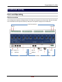
1
LSS PowerSwitch 12 x 20A Twelvefold switching actuator 20A (4600VA) for DMX512 and Profibus User Manual LSS GmbH Am Eichenberg 1, 04600 Altenburg Warnemünder Straße 1, 01109 Dresden www.lss-lighting.de Tel.: +49 3447 835500 Fax: +49 3447 861779 Tel.: +49 351 79565690 Fax: +49 351 79565699 PowerSwitch 12 x 20A Date: 09.01. 2013 All rights reserved. No part of this publication may be reproduced in any form (print, photocopy, microfilm or any other process) or reproduced by using of electronic systems, copied or distributed without the written permission of the LSS GmbH. The LSS GmbH is not liable for damages, losses, costs, and changes that have been made by unauthorized persons. This manual has been prepared with great care. Liability for negligent errors, e.g. misprints, is excluded. All mentioned names of products in this manual are trademarks of their respective companies. From the lack of trademarks ©, ® and ™ can not be concluded that the name is a free brand name. The Licht-, Steuer- und Schaltanlagenbau GmbH is certified member of the Profibus User Organization PNO. The ESTA-Manufacturer-ID of Licht-, Steuer- und Schaltanlagenbau GmbH is „LS“ (76,83 / 4Ch,53h). © 2013 LSS GmbH 2 PowerSwitch 12 x 20A Index Introduction .............................................................................................................................. 4 How to use this manual ....................................................................................................................4 Safety advices ...................................................................................................................................4 Instructions fore use PowerSwich 12 x 20A .....................................................................................5 Typical applications ................................................................................................................... 6 Typical applications of the PowerSwitch 12 x 20A ...........................................................................6 Functional survey....................................................................................................................... 7 Ports and Operating .........................................................................................................................7 Device overview ...........................................................................................................................7 Data Ports .....................................................................................................................................8 Power Supply ................................................................................................................................9 Relays............................................................................................................................................9 LED reports .....................................................................................................................................10 Overview ....................................................................................................................................10 DMX LED .....................................................................................................................................10 Profibus LED ...............................................................................................................................11 Configuration........................................................................................................................... 12 Priority of Data Signals ...................................................................................................................12 DMX Settings ..................................................................................................................................13 DMX adress ................................................................................................................................13 DMX signal ..................................................................................................................................13 Self-test ......................................................................................................................................13 Profibus Settings.............................................................................................................................14 Profibus address .........................................................................................................................14 Profibus termination ..................................................................................................................14 Profibus signal ............................................................................................................................14 Appendix A .............................................................................................................................. 16 Technical Data ................................................................................................................................16 General technical data ...............................................................................................................16 Ports ...........................................................................................................................................16 Relays..........................................................................................................................................16 Switching capacity ......................................................................................................................17 DMX ............................................................................................................................................17 Profibus ......................................................................................................................................18 LSS 3 PowerSwitch 12 x 20A Introduction How to use this manual This manual provides advices and information’s about the function and configuration of the PowerSwitch 12 x 20A. Like all devices of LSS GmbH the PowerSwitch 12 x 20A is constantly evolving technology. It is therefore possible that this manual does not explain later development forms. This manual uses the following symbols to indicate important information for your safety and for configuration. Here you get additional information’s. Attention alerts you to situations in which decisions can provoke to technical problems with the equipment or losing data. A Warning statement indicates situations in which can result in injury or damage to life and limb. Safety advices Proper care of the PowerSwitch 12 x 20A is not dangerous. However please note the following: Authorized personnel must install the device! Never operate with visibly damaged devices! If the suspect prior to a defect, immediately disconnect the device from the power supply! Secure the device to restart! Employees of the LSS GmbH may only make repairs! 4 PowerSwitch 12 x 20A Instructions fore use PowerSwich 12 x 20A The PowerSwitch 12 x 20A is designed for continuous operation. However please note the following: Use the device only for its intended purpose! Avoid extreme mechanical loads! Avoid direct exposure to moisture and excessive heat on the device! LSS 5 PowerSwitch 12 x 20A Typical applications Typical applications of the PowerSwitch 12 x 20A The PowerSwitch 12 x 20A is a switch assembly with bistable, poled relays in a compact de- sign. With it up to twelve independent resistive, inductive or capacitive loads can be switched. Each channel can supply loads up to 4600VA at 230V. Every switching status of each channel can be read directly on the switch actuator. The input control of the PowerSwitch 12 x 20A is done with Profibus (IEC 61158 / IEC 61784) or DMX512. So the switching actuator supports the two most popular control protocols in lighting and wiring installation. The PowerSwitch 12 x 20A is also equipped with a comfortable configuration. The front panel configuration switches will be set the DMX / Profibus start addresses, the switching behaviour at DMX signal loss and the termination of Profibus. In addition, the switching relays can also be switched manually directly on the device. The PowerSwitch 12 x 20A is designed for installation in electrical control cabinets and junc- tion boxes. For that he is equipped with a socket for DIN rail. 6 PowerSwitch 12 x 20A Functional survey Ports and Operating Device overview The configuration options of PowerSwitch 12 x 20A are situated on the front side. Electricals loads are connected at the top of the device, data ports und power supply at the underside. Load connections Load 1 Load 12 3 2 1 100 10 1 In Address 10h 1h Address LED Term. 321 LED LED DMX Profibus LSS Power supply 7 PowerSwitch 12 x 20A Data Ports DMX The DMX port is optically isolated and has an extensive EMC filter. DMX is connected as shown in the table: 3 2 1 Data + Data - GND Profibus Profibus is supplied via M12 connector (male & female) and forwarded. Using pre-assembled cables can save a lot of time during the installation of several power switches next to each other. The cable shield is loop through the metal sleeve. PIN-Assignment M12-B femal M12-B male 1 2 3 4 5 not connected A (green) not connected B (red) not connected The Ground is looped on the metal sleeve. Baud rate The PowerSwitch 12 x 20A support Profibus DP (Decentralized Peripherals) with full baud rate. A standard GSD file is available. 8 PowerSwitch 12 x 20A Power Supply The switch actuator requires 24V DC, which must be connected to the 3-pin 5.08mm terminal: 3 2 1 PE GND +24V The current consumption of the PowerSwitch 12 x 20A in rest is about 70 mA, in the switching with all 12 relays for the duration of the switching pulse about 2A. The switch pulse is about 30ms. The maximum switching rate is about 60ms (30ms pulse, 30 ms off). Relays The load is connected to 7.62 mm terminal strip. As shown in the image, two adjacent terminals are the closer of one relay. The following image shows the switching status of a relay: Off On LSS 9 PowerSwitch 12 x 20A LED reports Overview The LEDs have the following meanings from left to right: LED Colour Meaning DMX Green DMX reports, see below Profibus Yellow Profibus is in data exchange, Profibus is running Profibus Green Profibus reports, see below Power Green 24V DC power supply ON DMX LED DMX LED shows following reports: 10 Signal Meaning Off No incoming DMX signal present Short-time flash DMX test adresses 901…904 are adjusted Cyclical flash Incoming DMX signal incorrect (Data + / - reversed; wrong timing or level; false start code) or incoming RDM signals Permanently on Incoming DMX signal, HOLD is not active On and flashes at 1s timelag No incoming DMX or Profibus signal present, HOLD is active PowerSwitch 12 x 20A Profibus LED The green Profibus LED indicates the following reports: Signal Meaning Off No Profibus signal present (A/B reversed?) Short flash 1x Profibus signal present, data exchange impossible (false address, address not included into the master, cable A/B reversed) Blinking 1x Hardware failure, module is defective Blinking 2x Parameterization error. Check master programming! Blinking 3x Configuration error. Check master programming! Blinking 4x Hardware failure, module is defective Permanently on Data exchange ok, Profibus ok, no watchdog, HOLD active in case of data loss On and flashes at 1s timelag Data exchange ok, Profibus ok, watchdog ok, in case of data loss all data will be erased In addition, the following condition can occur: DMX and Profibus LEDs flashing quickly CPU clock incorrect (PLL error) due to extreme disturbances in the power supply or hardware failure, PowerSwitch 12 x 20A is defective LSS 11 PowerSwitch 12 x 20A Configuration Priority of Data Signals PowerSwitch 12 x 20A can receive DMX and Profibus signals simultaneously. The Profibus has always priority over DMX when the device is in the state of data exchange. This means there is no merging of data. Certain Profibus global control commands during the Data Exchange, e.g. PLC in STOP, cause an Off of all relays or, if HOLD is set, holding the last relay position. Without Data Exchange the control is on DMX. If the DMX signal is missing and depending of the HOLD settings, all relays are turned off or holding the last state. Is the incoming DMX signal switched off the DMX timeout of 2 seconds take effect. If the device is switched off and on again, the last switching state will be received for the first 3 seconds after the switch. Is HOLD active and none of the two input signals is present, the switching state is also obtained in addition. Otherwise, the relays will be switched in depending of the input signal or switched off when no input signal is present. PowerSwitch 12 x 20A is not able to detect the switching state of manually switched relays itself. These relays maintain their switching status until they are contacted directly by changing "their" bit or DMX circuit. 12 PowerSwitch 12 x 20A DMX Settings DMX adress Three decimal rotary switches sets the DMX address. From left to right: 100, 10, 1 Only addresses from 001 to 501 and test addresses m901 to 904 will be evaluated. All other addresses are invalid and their DMX data will be ignored. DMX signal PowerSwitch 12 x 20A uses the 12 circuits from the set address. Is the incoming value ≥50% (≥128) the relay is switched on. The timeout when no input signal is present is 2 seconds. Faulty protocols will be ignored. HOLD can be activated by using a higher Profibus switch (address ≥ 80h). The description of this follows in the "Profibus settings" Self-test A self-test can be activated with the DMX addresses 901 to 904: 901 = On/Off test of all relays with about 1 second 902 = On/Off test of all relays with about 60ms 903 = Running light with about 1 second 904 = Displays the firmware version with relays (1 = 1, 2 = 2,etc.) Never run the self-test with connected loads! LSS 13 PowerSwitch 12 x 20A Profibus Settings Profibus address Two hexadecimal rotary switches set the Profibus address. From left to right: 10h, 1h The addresses 00h to 7Eh are evaluated for Profibus. Addresses 80h to FEh are evaluated just as the addresses 00h to 7Eh but in addition, the HOLD function is activated. Example: Setting „0“ „4“ Setting „9“ „C“ = DP-address 04h (4 decimal) = DP-address 1Ch (28 decimal) and HOLD active Profibus termination Is PowerSwitch 12 x 20A located at the end of a Profibus bus segment; a slide switch can terminate the bus. Profibus signal The PowerSwitch 12 x 20A uses 4 Byte Out and 4 Byte In (4DO, 4DI). Parameter setting is not necessary. GSD file and bitmaps are present. I/O Byte Bit Meaning Out 0 0…7 Relay switching Bits 1…8 1 0…3 4…7 Relay switching Bits 9…12 Reserved 2 0…7 Reserved 3 0…7 Reserved 0 0…7 Relay Feedback 1…8 1 0…3 4…7 Relay Feedback 9…12 reserviert In 2, 3 15 1 word DMX diagnoses set DMX address (0…999) =1: DMX task is running Both =0: DMX signal is not present Both =1: DMX-Signal ok Or else frame error / polarity-reversed wire HOLD active 0…7 Relay Feedback 1…8 0…11 12 13 + 14 3 14 PowerSwitch 12 x 20A HOLD can be activated in two ways for Profibus failure: 1. With response When response is active, the green Profibus LED flashes unsteadiness. When response is not active (so HOLD is active), the green Profibus LED flashes permanently. 2. With the larger Profibus addresses (≥ 80h): At the input must be applied no DMX signal! The Profibus data will be hold in the DMX memory. Simatic STEP7 Watchdog: GSD file: Bitmap file: its a checkbox at the Profibus settings Copy the GSD file to …\STEP7\S7DATA\GSD Copy the Bitmap file to …\Step7\S7DATA\NSBMP Update the catalogue. The PowerSwitch 12 x 20A appears in "Profibus-DP - Additional Field Devices - IO - LSS". LSS 15 PowerSwitch 12 x 20A Appendix A Technical Data General technical data Design type: Setting elements: Dimensions: Power supply: Quiescent current: Operation current: Electric consumption: Weight: Security standards: RoHS-conform: Order number: housed hardware module for DIN-Rail rotary switches B x D x H (in mm) 217 x 63 x 90 10...30 V DC 0,1A 2,0A 2W 0,8kg IEC/EN 60950, UL/cUL 1950 (File E141988) yes 5048 Ports Profibus: DMX: 24V: Schaltausgänge: Binder Series 766 5-BU-LP und 5-ST-LP Phoenix MKDSN1,5/3-5,08 Phoenix MKDS2,5/3-5,08 Phoenix MKDS5/2-7,62 Relays Switch contacts: Minimum mechanical circle: Maximum switching current: Maximum switching power: Maximum switching capacity: Proof voltage: 16 AgSnO2 1.000.000 20 A 440 V AC 10 kVA / 15 kVA 1500 V eff. PowerSwitch 12 x 20A Switching capacity Filament lamp: Luminescent screen tabs uncomp.: Luminescent screen tabs parallel comp.: Halogen lamp (230V AC): Low voltage halogen lamp with transformer: Sodium/mercury vapour lamp: Dulux Compact Luminescent screen tabs uncomp.: Dulux Compact Luminescent screen tabs parallel comp.: 4800 VA 5000 VA 2500 VA / 200 µF 5000 VA 2000 VA 5000 VA 4000 VA 3000 VA / 200 µF (Information for 30.000 operations) DMX Number of Inputs: 1 Isolated ANSI E1.11 A1 Electrical isolator: Optocoupler Isolation volate: 1000V DC EMC: Filter switching Standards: USITT 1990, DIN 56930-2, ANSI E1.11 Baud rate: 250 kbps Start code: 0 Minimum protocol length: Start code only Maximum protocol length: Start code + 512 values (values over 512 will be lost) Minimum cycle delay: 44 s Maximum cycle delay: 22,5 ms Reception timeout: 2s Max. distance between 2 packets: 2 s Minimum realized break length: 48 s Maximum valid break length: 1,95 s LSS 17 PowerSwitch 12 x 20A Profibus Supported Baud rates: Station address: TSDRmin: PNO-Identnumber: GSD file: Diagnosis: Slave type: Slave character: Length output: Lenght input: Summary of Input/Output bytes: Profibus chip: Length user parameterization: Number of modules: 18 9,6 kBit/s...12 MBit/s 0...126 11 Bit times 0C51h available 1 Byte external diagnosis (parametrical) Compact slave FREEZE, SYNC, AUTOBAUD supported 4 Byte 4 Byte 8 Byte SPC3 1 Byte (SPC3 specific) 1