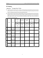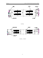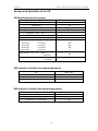
1
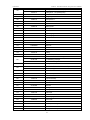
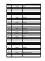
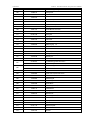
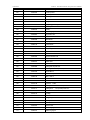
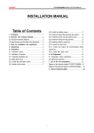
LAUNCH TLT235、TLT240 Luxurious Two-post User’s Manual LAUNCH TLT235/TLT240 Luxurious Two Post Lift User’s Manual Version No:1305 Launch (Shanghai) Machinery Co., Ltd i LAUNCH TLT235、TLT240 Luxurious Two-post User’s Manual Copyright reserved! Without the written agreement of This equipment is for the use of professional technical Launch Shanghai Machinery Co., Ltd. (hereinafter called personnel or maintenance personnel. “Launch”), no company or individual is allowed to copy and backup this manual in any form (electronic, mechanical, Registered Trademark photocopy, recording or other forms). This manual is specifically designed for the use of Launch product, and our company doesn’t undertake any responsibility for Launch has registered its trademark in China and several various consequences caused as a result of applying it to foreign countries, with the symbol of LAUNCH. Other the guidance of operating other equipment. trademarks, service symbol, domain name, icon, and company name of Launch mentioned in this manual belong In case of the equipment damage or loss due to the to the property of Launch and its subsidiary companies. In accident of the user himself or third party, abuse or misuse the countries where Launch’s trademark, service symbol, of this equipment, unauthorized change and repair of this domain name, icon and company name haven’t been equipment, or not conforming to the operation and registered, Launch declares its ownership on such maintenance requirement of Launch, Launch and its unregistered trademark, service symbol, domain name, branches won’t undertake any responsibility for the icon and company name. The trademarks of other products expenses and expenditures generated. and company names mentioned in this manual still belong to the originally registered companies. Without prior written For the equipment damage or problem caused as a result agreement of the owner, nobody can use the trademark, of using other optional accessories or consumables instead service symbol, domain name, icon and company name of of original Launch product or its recognized product, Launch and other companies mentioned in this manual. If Launch won’t undertake any responsibility. you have any question, please visit website of Launch: http://www.cnlaunch.com or write to Sales Dept. of Launch Official statement: The purpose of other- product- names Shanghai Machinery Co., Ltd. at No. 661 Baian Road, mentioned in this manual is to describe how to use this International Automobile City Auxiliary Parts Park, Anting equipment. Their registered trademarks still belong to the Town, Jiading District, Shanghai City to contact Launch. original companies. Insured by PICC i LAUNCH TLT235、TLT240 Luxurious Two-post User’s Manual WARNING z z z This instruction manual is an essential integral part of z lifting point as recommended by the manufacturer. Properly keep this manual for use during the Raise the carriage and confirm the lifting pad and maintenance. vehicle are closely contacted. Raise the carriage to Use only as described in this manual. Use only the appropriate working height. manufacturer’s recommended adapters. z z Position the swing arm of the lift, making it contact the this product. Please read all instructions. z For some vehicles, the parts dismantling (or This equipment is only used for its clearly designed installation) will cause severe deviation of the center purpose, and never use it for other purposes. of gravity, leading to unstable vehicle. The support is The manufacturer is not responsible for any damage needed to keep the balance of the vehicle. caused by improper use or other purposes of use. z Before moving the vehicle away from the lifting area, please position the swing arm and lifting pad back away to avoid blockage during the movement. z PRECAUTION z Only the qualified personnel having undergone boot, etc. special training can operate this machine. Without the z permission of the manufacturer or not following the z machine part and in the usage scope may cause z Don’t keep the lift in the extreme temperature and z Please refer the safety data of grease and oil shown Prevent the lift from contacting large amount of dust, in the manual. z prevent it from rain shower. z z Do not install lift in the open air or expose to be kept away from the machine. rain ,special requirements should be offered to Inspect machine daily ,do not use lift with damaged manufacturer if it can’t be avoided. z Carefully check equipment list before replace damaged parts installation .Immediately connect distributor or Launch The lift can’t be overloaded. The rated load of the lift for any question. is already marked on the nameplate. z Let components cool down before storage, loosen component cables completely in storage During the machine operation, non-operators should parts or being damaged .Use original components to z The hydraulic oil used for this lift is N32 or N46. heating equipment, water tap, air humidifier or stove. ammonia, alcohol, thinner or spray adhesive, and z Pay special attention not to dismantling the safety unit of the machine or making it not functioning. humidity environment. Avoid installation beside the z Keep hair, loose clothing, fingers, and all parts of body away form moving parts direct or indirect damage to the machine. z Pay special attention to various safety marks attached to the machine body. requirement of the manual, any changes in the z Use appropriate equipment and tools as well as safety protection facilities, e.g. working uniform, safety z Launch Shanghai Machinery Co., Ltd. is dedicated Please don’t raise the lift when there are people in the to continuously improving the product quality and vehicle. During the operation, the customer and upgrading the technical spec. They are subject to spectators shouldn’t stand in the lifting area. change without notice. Keep the lifting area free from obstacle, grease, machine oil, garbage and other impurities. ii LAUNCH TLT235、TLT240 Luxurious Two-post User’s Manual Caution Labeling Exemplification (1) (6)Use LAUNCH commend lifting points! Read operating and safety manuals before using lift! (7)Use bracket to help disassembly or installation! (2)Proper maintenance and inspection is necessary for safe operation! (8)Auxiliary adapters would reduce load capacity! (3)Don not operate a damaged lift! (9)Area should be unimpeded in case of vehicle overturn! (4)Lift can be used by trained operators ONLY! (10)The central of gravity should be between two arms! (5)Only Authorized personnel can be in the lift area! ii LAUNCH TLT235、TLT240 Luxurious Two-post User’s Manual (11)Keep area clear when lifting and lowering machine! (14)Keep feet away when lowering lift! (12)Do not shake the vehicle on the lift ! (15)Do not stand under carrying arms or other load carrying device while lift is being operated with load! (13)Do not lift single side of vehicle! ii LAUNCH TLT235、TLT240 Luxurious Two-post User’s Manual Table of Contents 1. OUTLINE.................................................................................................................1 1.1 MODEL DESCRIPTION .................................................................................................................................... 1 1.2 PURPOSE ....................................................................................................................................................... 1 1.3 FUNCTIONS AND FEATURES .......................................................................................................................... 1 1.4 TECHNICAL SPECIFICATIONS ........................................................................................................................ 1 1.5 ENVIRONMENTAL REQUIREMENT .................................................................................................................. 2 2. LIFT STRUCTURE..................................................................................................2 2.1 LIFT STRUCTURES ARE SHOWN AS BELOW:............................................................................................... 2 2.2 MAIN STRUCTURE PRINCIPLES:..................................................................................................................... 8 3 OPERATION DESCRIPTION...................................................................................9 3.1 PRECAUTIONS FOR VEHICLE REPAIR WORK.................................................................................................. 9 3.2 PREPARATION BEFORE OPERATION ............................................................................................................. 9 3.3 INSPECTION BEFORE OPERATION .................................................................................................................. 9 3.4 LIFTING THE VEHICLE .................................................................................................................................. 10 3.5 LOWERING THE VEHICLE ............................................................................................................................. 10 4 HYDRAULIC AND ELECTRICAL SYSTEM OF THE EQUIPMENT......................11 4.1 HYDRAULIC SYSTEM OF THE LIFT ............................................................................................................... 11 4.2 ELECTRICAL SYSTEM OF THE LIFT.............................................................................................................. 13 5. SOLUTIONS TO FAQ........................................................................................14 6. REPAIR AND MAINTENANCE.............................................................................15 7. STORAGE AND SCRAP ......................................................................................16 7.1 STORAGE ..................................................................................................................................................... 16 7.2 SCRAP.......................................................................................................................................................... 16 8. TOOLS FOR INSTALLATION AND ADJUSTMENT ............................................17 9. UNPACKING.........................................................................................................17 10. INSTALLATION ..................................................................................................17 10.1 IMPORTANT NOTICE ................................................................................................................................... 17 10.2 INSTALLATION PROCEDURE ...................................................................................................................... 17 10.2.1 Selecting installation site........................................................................................................................... 17 10.2.2 Base plate layout ..................................................................................................................................... 18 10.2.3 Install the power side column .................................................................................................................... 21 10.2.4 Install the floor plate, top beam .................................................................................................................. 23 10.2.4.1 Install the floor plate............................................................................................................................... 23 10.2.4.2 Install the top beam ............................................................................................................................... 23 10.2.5 Install the offside column........................................................................................................................... 24 10.2.6 Install and adjust the balancing steel cables................................................................................................ 24 10.2.7 Install the power unit and hydraulic lines..................................................................................................... 26 ii LAUNCH TLT235、TLT240 Luxurious Two-post User’s Manual 10.2.8 Install the swing arm................................................................................................................................. 27 10.2.9 Install the electric control box .................................................................................................................... 28 10.2.10 Adjust the Steel chain ............................................................................................................................. 29 10.2.11 Install and adjust the electromagnet safety mechanism .............................................................................. 30 11. LIFT ADJUSTMENT ...........................................................................................31 11.1 PREPARATION BEFORE THE ADJUSTMENT ............................................................................................................. 31 11.2 ADJUSTMENT PROCEDURE ................................................................................................................................. 31 12 LIST OF THE LIFT COMPONENTS ....................................................................32 13. SAFETY RULES OF ELECTRICAL SYSTEM....................................................50 GREASE AND HYDRAULIC OIL FOR LIFT ............................................................54 iii LAUNCH TLT235、TLT240 Luxurious Two-post User’s Manual 1. Outline 1.1 Model Description Model TLT235SBA Description floor-plate 2-post lift TLT235SBA(E) floor-plate 2-post lift 3.5T Luxurious symmetric floor-plate 2-post lift (Fig1a、Fig2a) 3.5T Luxurious symmetric wide floor-plate 2-post lift(Fig1b、Fig2b) clear-floor 2-post lift 4.0T Luxurious clear-floor 2-post lift (Fig1c、Fig2c) TLT235SCA(U) clear-floor 2-post lift 3.5T Luxurious clear-floor 2-post lift (Fig1d、Fig2d) TLT240SCA TLT240SBA floor-plate 2-post lift 4.0T Luxurious symmetric floor-plate 2-post lift (Fig1a、Fig2a) 1.2 Purpose z Lowering electrically, safe and simple in operation. This machine is applicable for the lifting of various small z Dual hydraulic cylinder and high strength chain drive, and medium-sized vehicles with total weight below 3.5t/4.0t stable lifting and lowering. z in garage and workshop. vehicle repair personnel. 1.3 Functions and Features z z The cable and oil pipe are fully concealed, with z Adopt two steel cables for equalization, force two decent and elegant appearance. carriages to move synchronously, and effectively Designed based on the international standard, prevent the vehicle from tilting. meeting the demand of the garage and workshop. z Cover for chain and chain wheel, protects safety of z Electromagnetic full-scope high-safety lock. Lowest height of lifting pad is 110mm, good for repairing low chassis or low profile car. 1.4 Technical Specifications Basic parameters of the equipment: Rising Net Passing Machine Machine weight width width height ≥20s ≤40s 620 kg 1367 lb 2486 mm 97.9 in 3370 mm 132.7 in 2860 mm 112.6 in ≤50s ≥20s ≤40s 735 kg 1620 lb 2486 mm 97.9 in 3400 mm 133.9 in 2900 mm 114.2 in ≤50s ≥20s ≤40s 655 kg 1444 lb 2486 mm 97.9 in 3370 mm 132.7 in 2860 mm 112.6 in 2486 mm 97.9 in 3420 mm 134.6 in 2415 mm 95.1 in 3563mm 140.3 in Rated Lifting load height TLT235SBA 3500 kg 7875 lb 1850 mm 72.8 in ≤50s TLT235SBA(E) 3500 kg 7875 lb 1850 mm 72.8 in TLT240SBA 4000 kg 9000 lb 1850 mm 72.8 in Model Desce time nding time TLT240SCA (Symmetric installation) TLT240SCA (Asymmetric 4000 kg 9000 lb 1850 mm 72.8 in ≤50s ≥20s ≤40s installation) 1 700kg 1543 lb 3840 mm 151.2 in LAUNCH TLT235、TLT240 Luxurious Two-post User’s Manual TLT235SCA(U) (Symmetric installation) TLT235SCA(U) 3500 kg 7875 lb (Asymmetric 1850 mm 72.8 in ≤50s ≥20s ≤40s 670kg 1477 lb installation) 2424 mm 95.4 in 3392 mm 133.5 in 2378 mm 93.6 in 3544mm 139.5 in 3840 mm 151.2 in Noise: Electrical parameters of the machine: Working noise: ≤ 75dB(A) Power unit: Working pressure: 16MPa (TLT235SBA) 16Mpa (TLT235SBA(E)) 16Mpa(TLT235SCA(U)) 18MPa(TLT240SBA) 18MPa(TLT240SCA) Motor (optional) Voltage:According to client’s requirement Single phase: 110V/60Hz 2.2kW ; 220V/50Hz 2.2 kW Single phase: 200V/60Hz 2.2 kW Three phase 380V/50Hz 2.2 kW 1.5 Environmental Requirement Working temperature: -5℃~+40℃ Relative humidity: Temperature +30℃,relative humidity 80% Transport/storage temperature:-5℃~+40℃ Height above sea level:No more than 2000m 2. Lift Structure 2.1 Lift structures are shown as below: Model TLT235SBA floor-plate 2-post lift TLT235SBA(E) floor-plate 2-post lift Description 3.5T Luxurious symmetric floor-plate 2-post lift (Fig1a、Fig2a) 3.5T Luxurious symmetric wide floor-plate 2-post lift(Fig1b、Fig2b) clear-floor 2-post lift 4.0T Luxurious clear-floor 2-post lift (Fig1c、Fig2c) TLT235SCA(U) clear-floor 2-post lift 3.5T Luxurious clear-floor 2-post lift (Fig1d、Fig2d) TLT240SCA TLT240SBA floor-plate 2-post lift 4.0T Luxurious symmetric floor-plate 2-post lift (Fig1a、Fig2a) 2 LAUNCH TLT235、TLT240 Luxurious Two-post User’s Manual 2750mm(108.3in) Power unit Control box Powerside column 110mm(4.3in) Carriage Electromagnet Lifting pad Arm assembly 3370mm(132.7in) Fig 1a Fig 1b 3 2860mm(112.6in) Offside column LAUNCH TLT235、TLT240 Luxurious Two-post User’s Manual Top beam Extension column Power unit Offside column Electromagnet Carriage min=110mm(4.3in) Control box Lifting pad Arm assembly 3420mm(134.6in) Fig 1c Fig.1d 4 3840mm(151.2in) 2750mm(108.3in) Powerside column LAUNCH TLT235、TLT240 Luxurious Two-post User’s Manual Fig 2a 300mm(11.8in) 2728mm(107.4in) Passing width 2486mm(97.9in) 800mm in) (31.5 120 (47 0mm .2i n) Drive-in direction 2586mm(101.8in) Fig 2b 5 LAUNCH TLT235、TLT240 Luxurious Two-post User’s Manual m ar n in) o i .8 ) ct se m(22 .1in e 0m 4 e 4 r Th n=58 0mm( mi =112 x ma m ar n) i ) n io .7 in ct 33 .7 se m( 53 o- 5m m( Tw =85 65m n mi x=13 ma Passing width 2486mm(97.9in) 3420mm(134.6in) m ar on 8in) i t ec (22. 1in) -s ee 80mm (44. r Th n=5 0mm mi =112 x ma m ar n) i ) n io .7 in ct 33 .7 se m( 53 o- 5m m( Tw =85 65m n mi x=13 ma Passing width2415mm(95.1in) 3563mm(140.3in) Fig 2c 6 LAUNCH TLT235、TLT240 Luxurious Two-post User’s Manual m ar n in) o i .8 ) ct se m(2 2 .1in e 0m 4 e 4 r Th n=58 0mm( 2 i 1 m =1 x ma m ar n) i ) n io .7 in ct 33 .7 se m( 53 o- 5m m( Tw 85 m n= 65 mi =13 x ma Passing width 2424mm(95.4in) 3392mm(133.5in) m ar on 8in ) i ct 22. in) se e- 0mm( 44.1 e r Th n=58 0mm ( m i =112 x ma m ar n) i ) n io .7 in ct 33 .7 se m( 53 o- 5m m( Tw =85 65m n mi x=13 ma Passing width 2378mm(93.6in) 3544mm(139.5in) Fig 2d 7 LAUNCH TLT235、TLT240 Luxurious Two-post User’s Manual 2.2 Main structure principles: z z z Lifting mechanism:Each column is installed with a hydraulic cylinder, when hydraulic oil is pressed from power pack into the lower chamber of main cylinder, piston rod moves upwards to drive the upward movement of carriage through leaf chain. Load supporting mechanism:When vehicle drives into the working area, adjust the angle and telescopic length of arms to make lifting pads at the effective load supporting position that contact with vehicle, then adjust the lower screw ’s height of lifting pad to make it applicable for vehicles with different chassis. Balance mechanism:In order to keep machine balanced during lifting and lowering, two carriages are interconnected and forced to move synchronously by two wire ropes. If the right and left carriages and arms are not at the same level, adjust the end nut of wire rope and pull wire ropes tight to make arms leveled. z z z z Fig 2e 8 Electromagnet safety lock mechanism: Each column is installed with two safety lock devices, when they start to work, this dual safety mechanism can make the machine stop reliably without falling during lifting process. Principles of electromagnet safety lock mechanism:The upper end of safety plate always attaches to the safety orifice closely. When the carriage rises, the safety orifice utilizes its inclined angle to push away the safety plate and rises progressively. In case of failure during the moving of the carriage, the rapid falling will occur, then the safety plate will block into the safety orifice, preventing the falling of the carriage (Fig. 3). When the electromagnet is actuated, the safety plate is released for carriage lowering (Fig.2e、2f) To prevent the vehicle slip, the swing arm is installed with positioning mechanism, making the swing arm capable of automatic locking during operation. Safety lock scope: Safety lock mechanism works when the front end of carriage is between 450mm and 1900mm high above the ground. LAUNCH TLT235、TLT240 Luxurious Two-post User’s Manual Fig 2f 3 Operation Description 3.2 Preparation before Operation 3.1 Precautions for vehicle repair work z z z z z Different vehicles have different center of gravity positions. First understand the position of center of gravity, and when the vehicle enters into the lift, make its center of gravity close to the plane formed by two columns. Adjust the swing arm, and make the lifting pad support onto the lifting point of the vehicle. Carefully read the warming symbol. The hydraulic valves have been adjusted before ex-factory, and the user can’t make self-adjustment, otherwise it will be responsible for all the consequences generated. Based on the production needs, some specifications in the instruction manual are subjected to change without notice z Lubricate contact surface of the carriage with general-purpose lithium grease(GB7324-87). All sliding surface should be coated evenly from the top to bottom. Fill hydraulic oil N32 or N46 to the oil reservoir of the power unit. 3.3 Inspection before operation z Check to see if the motor power is installed properly. z Check to see if all the connection Bolt s are fastened. Note: Don’t operate the lift with damaged cables or damaged and missing part, until it is inspected and repaired by the professionals. 9 LAUNCH TLT235、TLT240 Luxurious Two-post User’s Manual 3.4 Lifting the Vehicle z z z z z z z z z Keep work area clean, don’t operate the lift in cluttered work area. Lower the carriage to the lowest position. Reduce the swing arm to the minimum length. Swing the arm along the route of the vehicle Move the vehicle to the location between the two columns Swing the arm and put the lifting pad below the recommended lifting point, and adjust the height of lifting pad to touch lifting point of vehicle Press the UP button on the electric control box, slowly lift the vehicle to ensure the load balance, and then raise the lift to the required height. Release the UP button and the carriage will stop. Press the DOWN button to engage the safety lock of carriage. At this time, the vehicle can be repaired. hydraulic hose and fittings for oil leakage. In case of leakage, please don’t use the lift. Remove the fitting with leakage and re-seal. Re-install the fitting and check if oil leakage still exists. stand to maintain the balance of the vehicle. 3.5 Lowering the Vehicle z z z Before operation, the safety locking devices must be Inspected.1) The gear blocks of the z arm end must engage the gear block of the restraint shaft.2)No broken strand in the steel Clean the work area before lowering the vehicle. First press the UP button to raise the vehicle a little, then press and hold the UNLOCK button to disengage the safety lock, and then press DOWN button to lower the vehicle. Lower the vehicle till the swing arm down to the bottom and the lifting pads leave the vehicle chassis, and then release the two buttons. The swing arms under the vehicle must be fully shrunk Note: When the lift doesn’t work, you must cable. 3)No deformation in the arm pad. After the vehicle is lifted, when adding or removing any major heavy object, use jack Note: Before lifting the vehicle, check all the switch off the power. When lifting the vehicle, all the swing arms must be used. 10 LAUNCH TLT235、TLT240 Luxurious Two-post User’s Manual 4 Hydraulic and Electrical System of the Equipment 4.1 Hydraulic System of the Lift Diagram of the hydraulic system of clear-floor 2-post lift 9 9 8 8 6 4 5 2 1 3 7 11 10 1- Gear pump, 2- Motor, 3- Oil filter, 4- Check-valve, 5- Safety valve, 6- Solenoid valve, 7- Servo flow-control valve, 8- Hose, 9- Hydraulic cylinder, 10- Level gauge, 11- Air filter Fig 3a The working principle of the hydraulic system is as overflow will be happened inside safety valve to protect the follows: hydraulic system. Release the UP button to stop the oil When the UP button is pressed, the motor is started, supply and the lifting will stop. For lowering, press and hold driving the oil pump, sucking the hydraulic oil from the oil the UNLOCK button, the electromagnetic safety lock tank into the oil cylinder 9, forcing the piston rod move. At mechanism will be released, meanwhile press the DOWN this time, the safety valve 5 is closed, and the Max working button, the solenoid valve 6 is actuated, the hydraulic oil pressure is already adjusted before ex-factory. The safety flows back from the hydraulic cylinder into the oil tank valve can ensure the capacity of the rated load, but when through the solenoid valve 6 and flow-control valve 7, and the pressure in the system exceeds the limit, automatically the lift starts the lowering. 11 LAUNCH TLT235、TLT240 Luxurious Two-post User’s Manual Diagram of the hydraulic system of floor-plate 2-post lift 9 8 9 8 6 4 5 2 1 3 7 11 10 1- Gear pump, 2- Motor, 3- Oil filter, 4- Check-valve, 5- Safety valve, 6- Solenoid valve, 7- Servo flow-control valve, 8- Hose, 9- Hydraulic cylinder, 10- Level gauge, 11- Air filter Fig 3b The working principle of the hydraulic system is as overflow will be happened inside safety valve to protect the follows: hydraulic system. Release the UP button to stop the oil When the UP button is pressed, the motor is started, supply and the lifting will stop. For lowering, press and hold driving the oil pump, sucking the hydraulic oil from the oil the UNLOCK button, the electromagnetic safety lock tank into the oil cylinder 9, forcing the piston rod move. At mechanism will be released, meanwhile press the DOWN this time, the safety valve 5 is closed, and Max working the button, the solenoid valve 6 is actuated, the hydraulic oil pressure is already adjusted before ex-factory. The safety flows back from the hydraulic cylinder into the oil tank valve can ensure the capacity of the rated load, but when through the solenoid valve 6 and flow-control valve 7, and the pressure in the system exceeds the limit, automatically the lift starts the lowering. 12 LAUNCH TLT235、TLT240 Luxurious Two-post User’s Manual 4.2 Electrical System of the Lift Diagram of the electrical system E P H P 3 3 L V 0 8 2 3 L / V 0 2 1 2 L C A 2 B S 2 B S 1 B S 3 B S C Q 2 A K 3 B S T 2 B S 1 U F 2 A K ) A 3 ( / 3 U F ) A 5 . 0 ( / 2 U F D V ~ V 4 2 1 T S 2 B S M K M~ 3 Fig 3c M- Motor QC- Power switch KM- Contactor FU1- Fuse T- Transformer SB1- UP button SB2- DOWN button SB3- Into safety key SQ1- Upper limit switch SQ2- Lower limit switch VD- Bridge rectifier KA1、KA2- Intermediate relay H- Buzzer ST- Time relay YA - Electromagnet YV- Solenoid valve 13 LAUNCH TLT235、TLT240 Luxurious Two-post User’s Manual 5.Solutions to FAQ Symptom Reason Solution Check the circuit breaker or fuse Check the voltage to the motor ♦ Limit switch is failed Motor wire is burnt Motor is running, but Motor rotation reversed the lift can’t be raised. Solenoid valve body open. Hydraulic pump sucks the air Suction tube is separate from the Motor not operation Replace the burnt fuse or reset the circuit breaker Supply correct voltage for motor ♦ Replace the limit switch Replace the motor Change the motor rotating direction by changing wire connection. Repair or replace the solenoid valve body hydraulic pump Fasten all the suction pipe fittings Low oil level Replace the suction tube Add the oil into the oil tank Motor is running, the Motor is running under low voltage Supply correct voltage to the motor lift can be raised Impurities inside the solenoid valve Remove impurities from the solenoid without load, but the vehicle can’t be raised body valve body. Regulation pressure of safety valve is Adjust the safety valve incorrect Check the weight of the vehicle Lift is overloaded The lift is lowering Impurities on the solenoid valve body. Clean the solenoid valve body slowly without External oil leakage Repair the external leakage The lifting speed is Air and oil are mixed Replace the hydraulic oil slow or oil flows out of Air and oil suction are mixed Fasten all the suction pipe fittings the oil fill cap Oil return pipe is loosened Re-install the oil return pipe Adjust the balance cable to the proper pressing the down button The lift can’t rise Balance cable is not adjusted properly horizontally The lift is installed on the slop floor tension Shimming the columns to level the lift(no more than 5mm), If exceeding 5mm, pour new concrete floor and make it leveled. Refer to installation description. Anchor Bolt is not Hole is drilled too big fastened Concrete floor thickness or fastening big hole and reinstall the anchor Bolt , force is insufficient or use new drill to drill the hole for Pour the fast curing concrete into the re-positioning the lift Cut open the old concrete and make new concrete slab for the lift. Refer to installation description. 14 LAUNCH TLT235、TLT240 Luxurious Two-post User’s Manual 6. Repair and Maintenance Keep clean z z z This unit should be cleaned with dry cloth frequently to keep it clean. Before cleaning, first switch off the z z The working environment of this unit should be clean. In case of dust in the working environment, it will Check all the hydraulic lines for wearing Check to see if the carriage and the inner side of the speed up the parts wearing and shorten the service column are properly lubricated. Use high-quality life of the lift. heavy lubrication grease (lithium based lubrication grease GB7324-87). Every day: z Check all the chain connectors, Bolt s and pins to ensure correct installation power to ensure the safety. z Lubricate chains/cables. Before the operation, carefully check the safety Note: All the anchor Bolt s should be tightened mechanism of the lift to ensure the electromagnet suction and release action is proper, and the safety completely. If any screw doesn’t function for some plate is in good condition. When finding any abnormal reason, the lift can not be used until the bolt is situation, make adjustment, repair or replacement replaced immediately. z Check to see if the connection between hydraulic Every six months: z Check all the movable parts for possible wearing, interference or damage. z Check the lubrication of all the pulleys. If the pulley has dragging during the lifting and lowering, add appropriate lubricant to the wheel axle. z When necessary, check and adjust the balancing tension to ensure the horizontal lifting and lowering. z Check the verticality of the column. cylinder and carriage is proper, if the connecting nut between the steel chain and carriage is loose or falling. Refer to Fig.4 z Check to see if the steel cable connection is proper, and if the tension is at the optimum status. Note: The inner corner of each column should be lubricated with lubricant, to minimize the roller friction and ensure the smooth and even lifting. Maintenance of hydraulic system: z Clean and oil change In the six months after initial use of this unit, clean the hydraulic oil tank and replace the oil, later clean the hydraulic system once a year, and replace the oil. See Fig. 5. z Replace the seal After this unit is put into operation for certain period, if finding the oil leakage, carefully check it; if the leakage is due to the wearing of sealing materials, immediately replace the worn one based on the original spec. See Fig. 5 Fig 4 Every month: z Retighten the anchor Bolt s. 15 LAUNCH TLT235、TLT240 Luxurious Two-post User’s Manual Diagram of hydraulic line of clear-floor 2-post lift JB/T982-77 seal gasket 14 JB/T982-77 seal gasket 14 JB/T982-77 seal gasket 14 Diagram of hydraulic line of floor-plate 2-post lift Fig 5 Wearing Parts No. Name Model Spec Qty 1 O rubber sealing ring GB3452.1-92 53×5.3 1 DHS40 1 UHS53×63×6 1 2 Dust proof ring 3 Shaft sealing ring 4 Rubber pad 4 Remark Self-made part z Empty all the oil/liquid storage units 7. Storage and Scrap z Put the plastic cover over the equipment for dust protection 7.1 Storage 7.2 Scrap When the equipment requires long-time storage: When the equipment service life is expired and can no z Disconnect the power supply longer be used, disconnect the power supply, and properly z Lubricate all the parts requiring lubrication: mobile dispose of as per relevant local regulations. contact surface of the carriage, etc. 16 LAUNCH TLT235、TLT240 Luxurious Two-post User’s Manual 8. Tools for Installation and z Adjustment level of the lifting relies on the level of the floor where it is installed. Don’t expect to compensate for the To ensure proper installation and adjustment, please serious slope. prepare the following tools:: z Don’t install the lift on any asphalt surface or any Tool Model surface other than concrete. The lift must be installed Leveling instrument Carpentry type on concrete floor conforming to the minimum Chalk line Min 4.5m requirement showed in this manual. Don’t install the Hammer 1.5kg lift on the concrete with seams or crack and defect. Medium crescent wrench 40mm Please check together with the architect. Open-end wrench set 11mm-23mm z Flat Screw driver 150mm z Rotary hammer drill 20mm Concrete drill-bit ¢19mm Without the written approval of the architect, don’t install the lift on a second floor with basement. Ratchet socket set Overhead obstruction: The lift installation area can’t have any overhead obstruction, such as heater, building support, electrical pipe, etc. z Concrete drilling test: The installation personnel can test the concrete thickness at each site by drilling test. If several lifts are installed at one place, it is preferred 9. Unpacking to make drilling test in each site. Power supply: Get ready the power supply before the Open the packing box; remove the packing materials and inspect the lift for any sign of shipment damage. Check by packing list to see if the main parts and accessories are complete. z Keep the packing materials away from the children to avoid danger; if the packing materials cause the pollution, they shall be treated properly. 10.2 Installation Procedure installation. All the electric wiring and connecting should be performed by a certified electrician. 10.2.1 Selecting installation site Selecting installation site based on the following conditions: 10. Installation z must have a minimum thickness of 250mm and 10.1 Important notice z should be aged 7days at least . The wrong installation will cause the lift damage or z personal injury. The manufacturer will not undertake The concrete slab shall have reinforcement by steel bar. any responsibilities for any damage caused due to incorrect installation and usage of this equipment, whether directly or indirectly. z Lift can only be installed on concrete slab, which z The concrete slab must be leveled. z If the thickness of the whole ground concrete is greater than 250mm, the lift can be installed directly The correct installation location shall be “horizontal” z floor to ensure the horizontal lifting. The slightly slope Check the possible obstruction, e.g. low ceiling, top pipeline, working area, passage, exit, etc. floor can be corrected by proper shimming. Any big z slope will affect the height of the lifting pad when at The front and back of the lift should be reserved with sufficient space to accommodate all the vehicles (Fig. the bottom or the horizontal lifting. If the floor is of 6).(evaluating from the center line ,each edge should questionable slope, consider a visual inspection, or be about 4m) pour a new horizontal concrete slab if possible. In short, under the optimum horizontal lifting status, the 17 LAUNCH TLT235、TLT240 Luxurious Two-post User’s Manual Entrance Recommended 4.0m Fig 6 chalk line, and mark the total width (B) of the base 10.2.2 Base plate layout z plate. Mark the points 3 and 4. Starting from point 3, TLT235SBA、TLT240SBA Models:With total width draw one diagonal line (C) ,forming a triangle. In this (A) as the basis, draw two parallel lines (#1 and #2) way, the vertical lines can determine the location of on the concrete slab, with the error within 3mm. the two columns.(as shown in 7a) Determine the power side column location on any 1# 2# 2610mm(102.8in) C 235mm 235mm (9.3in)(9.3in) 520mm B (20.5in) 25mm(1in) A 3370mm(132.7in) 对 角 线 34 1 0m 3 i n) m( 13 4. 3 Diagonal 3410mm(134.3in) φ 4 22 mm 2770mm(109.1in) (0 380mm (15in) .9 in ) Fig 7a 18 LAUNCH TLT235、TLT240 Luxurious Two-post User’s Manual TLT235SBA(E)Model:The Base plate and four pieces shown in Fig.7b) corrugated steel plate are connected by fasteners.(as Fig.7b TLT240SCA Model: z Base plate symmetric installation is as shown in 7c1: With total width (A) as the basis, draw two parallel lines (#1 and #2) on the concrete slab, with the error within 3mm. Determine the power side column location on any chalk line, and mark the total width (B) of the base plate. Mark the points 3 and 4. Starting from point 3, draw one diagonal line (C) , forming a triangle. In this way, the vertical lines can determine the location of the two columns. A 1# 3420mm(134.6in) B 400mm(15.7in) 70mm(2.8in) 2# 2610mm(102.8in) C 3 ) mm(135.6in 对角线3443 Diagonal 3443mm (135.6in) 4 2820mm(111in) Fig.7c1 down 131mm, then move right 228mm to get point C. Base plate asymmetric installation is based on a total width Based on point B, draw #1’s vertical line M with a length of (A) shown in 7c2, draw two parallel lines (#1 and #2) on the A to get point D .Based on point C, draw line M’s parallel concrete slab, with the error within 3mm.Determine a point line N with a length of L to get point E. With four points B at any point on chalk line #1, based on point B, move B,C,D,E, each post’s position can be decided. 19 LAUNCH TLT235、TLT240 Luxurious Two-post User’s Manual A 131mm(5.16in) 1# 2# 3563mm(140.28in) B D C E 228mm (8.98in) 228mm (8.98in) 3107mm(122.32in) Fig. 7c2 TLT235SCA(U)Model: z Base plate symmetric installation is as shown in 7d1: With total width (A) as the basis, draw two parallel lines (#1 and #2) on the concrete slab, with the error within 3mm.Determine the power side column of the base plate. Mark the points 3 and 4.Starting from point 3, draw one diagonal line (C), forming a triangle. In this way, the vertical lines can determine the location of the two columns. A 1# 2# 3392mm(133.54in) 70mm (2.76in) 2582mm(101.65in) 400mm(15.75in) B location on any chalk line, and mark the total width (B) 3 C 34.47in) 3415.5mm(1 4 2792mm(109.92in) Fig.7d1 Base plate asymmetric installation is based on a total width Based on point B, draw #1’s vertical line M with a length of (A) shown in 7d2,draw two parallel lines (#1 and #2) on A to get point D .Based on point C, draw line M’s parallel the concrete slab, with the error within 3mm.Determine a line N with a length of L to get point E. With four points point B at any point on chalk line #1, based on point B, B,C,D,E, each post’s position can be decided. move down 131mm, then move right 228mm to get point C. A 131mm(5.16in) 1# 2# 3544mm(139.53in) B D C 228mm (8.98in) 3088mm(121.57in) Fig 7d2 20 228mm E (8.98in) LAUNCH TLT235、TLT240 Luxurious Two-post User’s Manual Note: z 10.2.3 Install the power side column All the dimensions are based on the external TLT235SBA、TLT240SBA Models: border of the base plate. z Ensure the overall error is controlled within 6mm. First use lifting equipment to put the power side In this way, the difficulties in the final assembly, column upper right to the location. Align the base plate of or early wear or non-alignment of the chain can column with the chalk line layout.Guided by holes on the be eliminated. The marking and layout is very base plate of the column, use 5 concrete anchor Bolt s to important. If it is inaccurate, there will be fix it onto the ground. Drill and install anchor Bolt s at one problems time, during the drilling process, ensure no movement of during the final assembly and the column from the chalk line (Fig.8a). operation. Fig. 8a anchor Bolt s at one time, during the drilling process, ensure no movement of big base plate and side brackets, as shown in 10b.Insert appropriate shims under big base plate and side brackets ,to plumb columns and make sure no inclination would be more than 3mm. TLT235SBA(E)Model: z Place the big base plate and side brackets to pre-calculated position. Use lifting equipment to place columns at pre-calculated position and fix them by using standard installation parts,. Guided by holes on the big base plate and side brackets, use 12 concrete anchor Bolt s to fix it onto the ground. Drill and install 21 LAUNCH TLT235、TLT240 Luxurious Two-post User’s Manual Fig.8b TLT240SCA、TLT235SCA(U)Models: plate of the column, use 5 concrete anchor bolts to fix it First install extension column with column, then onto the ground. Drill and install anchor Bolt s at one use lifting equipment to place power side column upper time, during the drilling process, ensure no movement right to the location. Align the base plate of column with of the column.(Fig.8c) . the chalk line layout. Guided by holes on the base Fig.8c ♦ Note: ♦ Use sharp Φ19mm concrete drill-bit to drill the holes so as not to drill the hole too large,. Use proper pneumatic tool to remove the dust from the hole. The depth of the hole is the same as that of the anchor Bolt . Insert the anchor Bolt and make the washers lean against the base of the column. Only use torque wrench instead of impact tools to fasten anchor Bolt s. Insert proper steel shim under the base seat of column to plumb the column. Note: The thickness of shims shouldn’t exceed 5mm. 22 LAUNCH TLT235、TLT240 Luxurious Two-post User’s Manual To get the correct and safety installation, please follow Note: Since the offside column is not fixed to the ground, you must operate carefully to avoid the falling of the column. The wire protective pipe on the floor plate must be in same direction with the pipe on the column near the base. And the floor plate would be placed in front position. the following installation steps. z Wear the safety goggles z Use hard alloy drill-bit. z Don’t use the drill-bit with wearing exceeding the tolerance. z The drill and concrete surface should be kept perpendicular. z Let the drill work itself. Don’t apply the extra force, and don’t ream the hole or allow the drill to wobble. z The drilling depth of hole is based on the length of 10.2.4.2 Install the top beam anchor Bolt .The distance from the Bolt head to the TLT240SCA、TLT235SCA(U)Models: concrete floor should be more than twice of the Bolt Position the offside column at the designated chalk location. diameter. z z Lift the top beam to its high position, and use four M12 Bolt Remove the dust from the hole. s, washers and lock nuts to fix it with the columns (as Gently tap the Bolt into the hole till the washer rests shown in Fig. 9a). When installing the top beam, ensure against the base plate of column. z the above micro switch support bracket adjacent to the Fasten Bolts power side column. In Fig 9a:The symmetric top pulleys are to be installed at position 1、1″,asymmetric top pulleys 10.2.4 Install the floor plate, top beam are to be installed at position 2、2″. 10.2.4.1 Install the floor plate TLT235SBA、TLT235SBA(E)、TLT240SBA Models: Note: Since the offside column is not fixed to Position the offside column at the designated chalk line the ground, you must operate carefully to avoid the location, carefully making the base align with the chalk line falling of the column. layout. Insert the floor plate into the U gaps of the base seat of two columns. 23 LAUNCH TLT235、TLT240 Luxurious Two-post User’s Manual Diagram of column, extension column and top beam 2 1 1″ 2″ Top pulley Connection bracket 8-M12×35 Hex bolt Extension column 16-12 flat washer 6-M10×20 Hex bolt 6-10 flat washer 8-12 spring washer 8-M12 nut 6-10 spring washer 16-M12×35 Hex bolt 32-12 flat washer 16-12 spring washer 16-M12 nut Column Fig 9a 10.2.5 Install the offside column z Install the offside column as the procedures in10.2.3. z 10.2.6 Install and adjust the balancing steel cables z Raise the two carriages to the safety locking position, make sure the two carriages are of the same height from ground. for TLT235SBA、TLT235SBA(E)、 24 TLT240SBA models, route the steel cables as Fig. 9b shows ,for TLT240SCA、TLT235SCA(U)models, route the steel cables as Fig9c shows.. Adjust the tension of cables through the adjustment nuts on each end of steel cable. The steel cables should be tight in equal tension. Each steel cable should be ensured in the pulley when adjusting tightly, otherwise the steel cable will be damaged. LAUNCH TLT235、TLT240 Luxurious Two-post User’s Manual Short screw end, double nuts tightened Long screw end, adjustable Steel cable Fig 9b Fig 9c 25 LAUNCH TLT235、TLT240 Luxurious Two-post User’s Manual (E)、TLT240SBA models, install the hydraulic line Note: as shown in Fig. 10a , for TLT240SCA、TLT235SCA The two steel cables are required to adjust (U)models, , install the hydraulic line as shown in to certain uniform tension to ensure the two Fig. 10b and tighten all the fittings to prevent oil carriages move synchronously. leakage. Short Screw must be installed in the way z as shown in above Fig. The tightened Operate carefully to avoid dust and other pollutants double nuts are nonadjustable otherwise it mixed with the hydraulic oil. will affect the safety use of lift. Note: Clean the impurities in the hydraulic line and remove the protective plug from the hydraulic cylinder. When the hydraulic hose installation needs to go through the column, ensure the hydraulic hose won’t touch any movable parts inside the column Before operating the lift, re-check the balancing steel cables and ensure they are not intersected or wrongly installed. Ensure the steel cables are still in the pulley. 10.2.7 Install the power unit and hydraulic lines z Fill the reservoir with hydraulic oil (oil capacity of 10L). Use two M10 Bolt s and washers to fix the power unit as shown in Fig. 10a, for TLT235SBA、TLT235SBA Fig 10a 26 LAUNCH TLT235、TLT240 Luxurious Two-post User’s Manual Fig.10b 10.2.8 Install the swing arm Install the swing arm as shown In Fig.11 Note: Before use ,check if the positioning gear mechanism at the end of arm fits, adjust the Screw s of fixed semi-gear for its fitness. During the installation, lubricate the moving parts of swing arm and carriage if accessory, so that the swing arm can move freely. Fig 11 27 LAUNCH TLT235、TLT240 Luxurious Two-post User’s Manual should be bought and installed by users. The NFB is 10.2.9 Install the electric control box z 16A. Use M5x12 Screw and washer to fix the electric The power cable is required to be greater than 2.5mm2. Coat the roller and carriage passage with the lubrication grease. Raise and lower the carriages twice without load t o see if they work well. After the column is fixed, operate with load control box casing onto the column.(Fig.12) z z Connect the electrical wiring as shown in Fig. 12. Install the bottom case of the electric control box. Note: Installation schematic diagram of electric control box This equipment needs NFB (non-fuse breaker) upon installation. This equipment does not include it. It M4*6 Screw Fig 12 Wiring diagram z TLT235SBA、TLT235SBA(E)、TLT240SBA models are shown in Fig13a. z 28 TLT240SCA、TLT235SCA(U)models are shown in Fig13b. LAUNCH TLT235、TLT240 Luxurious Two-post User’s Manual Fig 13a Fig 13b electrical and hydraulic installation. Before adjustment, lift 10.2.10 Adjust the Steel chain the carriage to a high position and lower for 2 sec to The steel chain has been adjusted properly by the engage safety lock, and then adjust the nut on the manufacture (Fig. 14), making the swing arm move freely threaded end of the chain to the required position. Raise at the lowest height without scratching the ground. The carriage to disengage safety lock and operate as required. customer can make fine adjustment for chains after the 29 LAUNCH TLT235、TLT240 Luxurious Two-post User’s Manual 式链 Leaf板chain 调节螺 Adjustment bolt栓 连 接 螺 nut 母 Connection Fig 14 z 10.2.11 Install and adjust the electromagnet safety mechanism z Press UNLOCK button to actuate the electromagnet, and see if two safety plates can completely separate Use Bolt s M5x12 and flat washer 5 to fix the from the carriage safety orifice. electromagnet, and use Bolt s M6×20 to fix safety (See Fig. 2f) plate by supporting block(as shown in Fig. 3) z Adjust the electromagnet rear end nut. When the Note: safety plate is under the safety status, the plate The electromagnet installation shall ensure free pulling and release. It is not allowed to have any jammed resistance caused by back cover or others. should contact the carriage; meanwhile, there is 1-2mm gap between the nut and the end of electromagnet. When the carriage rises, the safety orifice utilizes its inclined angle to push away the 10.2.12 Install the cover, floor plate cover safety plate and rises progressively. The rattling sound can be heard clearly in the two columns. (See Fix the electromagnet cover. Install the floor plate cover Fig.2e and 2f) onto the guide plate to cover the oil hose and steel cables. 30 LAUNCH TLT235、TLT240 Luxurious Two-post User’s Manual 11. Lift Adjustment 11.1 Preparation before the adjustment z Lubricate contact surface of the carriage and corners z of column with general-purpose lithium grease. All sliding surface should be coated evenly from top to bottom. Fill hydraulic oil N32 or N46 to the oil reservoir of the power unit. 11.2 Adjustment procedure 1 3 2 DOWN UP UNLOCK 5 4 6 1. UP button 4、Buzzer 2. Unlock button 5、220V waterproof socket Note : This equipment needs NFB (non-fuse breaker) upon installation. This equipment does not include it. It should be bought and installed by users. 16A NFB is suggested. 3. DOWN button 6. Power switch stops at the lower limit switch position (CE-STOP),release the button and keep pressing DOWN button until the lift lowers to its bottom . Buzzer:Before lift falls to the lower limit z z z Check if the motor power is installed correctly. switch(CE-STOP),the buzzer doesn’t alarm, when Check if all connecting Bolt s are fastened. release and repress the DOWN button, during its Operation procedures as follow: lowering process from lower limit switch position Rising process:Push UP button, the carriage goes up, (CE-STOP)to bottom ,there would be a buzzer release the button , the carriage stops; alarm . z Locking process:Push DOWN button, the carriage Bleeding is required for newly installed hydraulic lowers to the safety block. system .When connection pipes ,the hydraulic Lowering process:Push DOWN button ,it goes up for cylinder should be at its lowest position for minimum 2 seconds to disengage safety lock ,then lowers and air cavity ,then raise and lower for several times . z 31 The adjustment is finished. LAUNCH TLT235、TLT240 Luxurious Two-post User’s Manual 12 List of the Lift components case of damages to the components, purchase can be made from the LAUNCH and its sales agents based on the corresponding material code No in the list. This list is only used as the information for the maintenance and repair. Our company will not be liable for other uses. In Applicable to TLT235SBA/TLT240SBA; 32 LAUNCH TLT235、TLT240 Luxurious Two-post User’s Manual Applicable to TLT235SBA/TLT240SBA(E)/ TLT240SBA: 33 LAUNCH TLT235、TLT240 Luxurious Two-post User’s Manual Applicable to TLT235SBA/ TLT240SBA/ TLT240SCA/TLT235SCA(U) 34 LAUNCH TLT235、TLT240 Luxurious Two-post User’s Manual Applicable to TLT235SBA/TLT235SBA(E)/TLT240SBA/ TLT240SCA/TLT235SCA(U) 316 317 305 306 308 302 303 304 315 301 318 314 309 306 307 306 312 320 311 310 319 322 321 35 306 313 LAUNCH TLT235、TLT240 Luxurious Two-post User’s Manual Applicable to TLT235SBA(E) 36 LAUNCH TLT235、TLT240 Luxurious Two-post User’s Manual Applicable to TLT235SBA(E) 37 LAUNCH TLT235、TLT240 Luxurious Two-post User’s Manual Applicable to TLT240SCA 38 LAUNCH TLT235、TLT240 Luxurious Two-post User’s Manual Applicable to TLT240SCA/TLT235SCA(U) 39 LAUNCH TLT235、TLT240 Luxurious Two-post User’s Manual Applicable to TLT235SBA/ TLT240SBA/ TLT240SCA/TLT235SCA(U) 40 LAUNCH TLT235、TLT240 Luxurious Two-post User’s Manual Applicable to TLT235SCA(U) 41 LAUNCH No. TLT235、TLT240 Luxurious Two-post User’s Manual Code Name 201024756 TLT235SBA power side column 201024757 TLT240SBA power side column 201024755 TLT235SBA offside column 201024758 TLT240SBA offside column 3 103202906 Installation plate of power unit 4 103020190 Screw M6×10 5 103040123 Flat washer 10 6 103040122 Spring washer10 7 103020038 Bolt M10×25 8 103260337 Steel cable 9 201020381 Top cover assembly 11 103203017 Pulley 12 103200699 Bushing 2520 13 103040176 Washer 14 103050031 Returning ring 25 15 103050037 Returning ring 16 103040177 Spring washer8 17 103020116 Bolt M8×16 18 103040110 Flat washer12 19 103040044 Spring washer12 20 103020104 Bolt M12×35 21 103202821 Floor plate 22 103202819 Floor plate cover 23 103020123 Anchor Bolt M18×160 24 103202860 Protective cover inside the column 25 103200942 Safety block 26 103202520 Supporting block 27 103040133 Flat washer6 28 103040027 Spring washer6 29 103020099 Screw M6×20 30 103200960 Electromagnet 31 103010432 Screw M5X12 32 104120078 Electromagnet cover 33 201011236 Bottom cover of column 48 103010426 Screw M4×12 49 103010429 Screw M4×25 53 102100197 Roller type limit switch(turn 180) 54 103202981 Limit bottom plate 55 103020156 Bolt M6*12 1 2 101 Power unit 42 LAUNCH TLT235、TLT240 Luxurious Two-post User’s Manual 103100170 Fitting M14×1.5(for domestic pump) 103100171 Fitting G1/4″(for imported pump) 103 104120066 Oil hose 104 103202197 Long fitting 105 103040157 Seal gasket 14 106 103260098 Bush 3052 107 104120079 Oil hose 108 103260123 Main cylinder 109 103260129 Sub cylinder 110 103220054 Sheave seat 111 104060016 Returning ring 32 112 103050014 Returning ring 30 113 103201950 Sheave 114 103200973 Sheave axle 115 103200939 Steel chain 116 X103060340 Pin 2×26 117 103200938 Chain threaded end 118 103030131 Nut M16 119 103100170 Fitting 201021324 TLT235SBA/TLT240SBACarriage 201021793 TLT235SCA(U) Carriage 201021323 TLT235SCACarriage 104990132 Sliding block 103202766 TLT235SBA/TLT240SBA/TLT235SCATop board 103202765 TLT235SCA(U) 204 103010473 Screw M10×30 205 104130191 Door rubber pad 206 103010452 Screw M8×16 207 103202184 Top rod assembly 208 103202032 Semi-gear 209 103010443 Screw M10×25 210 201010982 Pin axle 211 201020501 Swing arm 212 103201914 Spring 213 103201744 Gear block 214 103020093 Screw M8×16 215 103050030 Returning ring 40 216 103060355 Pin 3.2X30 217 103060376 Pin 5X32 218 104130186 Rubber pad on swing arm 219 103010414 Screw M5X8 220 103202130 Lifting pad assembly 102 201 202 203 43 LAUNCH TLT235、TLT240 Luxurious Two-post User’s Manual 221 104130189 Rubber pad 222 201014617 The limiting plate 301 103200932 Base plate of control box 302 103010432 Screw M5×12 303 103040166 Spring washer5 304 103040132 Flat washer5 305 102100198 Transformer 306 103010423 Screw M4×6 307 102110051 Electromagnetic Relay DC24V 308 103040048 Spring washer4 309 102110067 Time Relay DC24V 310 102150053 102150054 102150055 Fuse RT18-32/3P(10 A core) (380V three-phase control box) Fuse RT18-32/3P(20A core) (220V three-phase control box) Fuse RT18-32/2P(32A core) (220V single-phase control box) 311 102110059 Contactor S-P11,AC,24V 312 102990067 Ground plate ¢5 313 102160390 Terminal 314 102100199 Button (black, one contact closed, one contact open) 102100200 Button (black, two contacts closed, two contacts open) 102100201 Button(yellow,one contact closed, one contact open) 315 104090050 Display board 316 104091176 Case of control box 317 103010412 Bolt M4×6 318 103200802 Sliding guide 319 102100087 Power switch 320 102140018 Buzzer 321 104091175 Bottom case of control box 322 102160392 Water proof socket 401 201024781 TLT235SBA(E)power side column 402 201024762 TLT235SBA(E)off side column 403 103202906 Installation plate of power unit 404 103020190 Screw M6×12 405 103040123 Flat washer 10 406 103040122 Spring washer10 407 103020120 Bolt M10×20 408 103260339 Steel cable 409 201024766 TLT235SBA(E)Top cover 411 103203017 Pulley 44 LAUNCH TLT235、TLT240 Luxurious Two-post User’s Manual 412 103200699 Bush 2520 413 103040176 Washer 414 103050031 Steel cable returning ring 25 415 103050037 Returning ring 416 103040141 Spring washer8 417 103020116 Bolt M8×16 418 103040110 Flat washer12 419 103040044 Spring washer12 420 103020104 Bolt M12×35 421 103202862 Pulley seat 103202863 Pulley seatⅡ 422 103010607 Zinc Screw M12×30 423 103020123 Anchor Bolt M18×160 424 103202860 Protective cover inside the column 425 103200942 Safety block 426 201011198 Supporting block 427 103040133 Flat washer6 428 103040027 Spring washer6 103020099 Screw M6×20 430 103200960 Electromagnet 431 103010432 Screw M5X12 432 104120078 Electromagnet cover 433 201011236 Bottom cover of column 434 201021451 Protective cover 435 103010608 Screw M6×10 436 103030127 Nut M8 437 201021455 Base seat bracket 438 103020187 Bolt M18×50 439 103040169 Flat washer18 440 103040142 Spring washer18 441 201021459 Bracket 201021460 BracketⅡ 442 201013136 Ramp 443 X201013127 Cover plate 444 103010539 Screw M8×12 445 103050035 Returning ring 25 446 103020156 Bolt M6×12 447 103010429 Screw M4×25 448 102100197 Roller type limit switch(turn 180) 449 103010426 Screw M4×12 450 103202981 Limit bottom plate 429 45 LAUNCH TLT235、TLT240 Luxurious Two-post User’s Manual 501 201021454 TLT235SBA(E) carriage 502 104990132 Sliding block 503 103202766 Top board 504 103010473 Screw M10×30 505 104130191 Door rubber pad 506 103010539 Screw M8×12 507 103202184 Top rod assembly 508 103202032 Semi-gear 509 103011102 Screw M10×25 12.9 class 510 103202280 Pin axle 511 201021738 Swing arm 512 103201914 Spring 513 103201744 Gear block 514 103010260 Screw M8×20 515 103050030 Returning ring 40 516 103060355 Pin 3.2×30 517 103060376 Pin 5×32 518 201014617 Actuator plate 520 103202130 Lifting pad assembly 521 104130189 Rubber pad 201025027 TLT240SCA(U)power side column 201020620 TLT240SCA power side column 201021792 TLT240SCA(U) offside column 201020618 TLT240SCA offside column 603 201020928 Extension column 604 103202860 Inner cover of power side column 605 103202859 Cover of extension column 606 103200960 Electromagnet 607 104120078 Electromagnet cover 608 103010498 Screw M5×8 609 103202811 Connecting bracketⅠ 610 103040110 Flat washer12 611 103040044 Spring washer12 612 103020104 Bolt M12×35 613 103202812 Connecting bracketⅡ 614 103040123 Flat washer10 615 103040122 Spring washer10 616 103020120 Bolt M10×20 617 201011176 Reinforced plate 618 103010429 Screw M4×25 619 103201545 Bracket 601 602 46 LAUNCH TLT235、TLT240 Luxurious Two-post User’s Manual 620 105990008 Limit switch 621 103202816 Inner top beam 622 103202818 Outer top beam 623 201011258 Bushing Ⅰ 624 103060342 Pin 3x26 625 201011170 Long bar 626 201011172 Supporting pin of long bar 627 201012602 BushingⅡ 628 104090045 Pulley 629 103050035 Returning ring 25 630 103200967 Symmetric axle 103200966 Asymmetric axle 631 103020099 Bolt M6×20 632 103040027 Spring washer6 633 103040133 Flat washer6 634 103200942 Safety plate 635 103202520 Supporting block 636 103201073 Bracket for extension sleeve 637 103201070 Bottom cover of column 638 103010582 Anchor bolt M18×160 103020123 Anchor bolt M18×160 639 103260257 Steel cable 641 103020090 Screw M6×10 642 103202906 Fixing plate of power unit 643 102100197 Roller type limit switch(turn 180) 644 103010426 Screw M4×12 645 103202981 Limit bottom plate 646 103020156 Bolt M6×12 701 Power unit 702 104120136 Oil hose L=880 703 103100170 Fitting M14×1.5(for domestic power unit) 103100171 Fitting G1/4〞(for imported power unit) 704 104120096 Oil hose L=5370 705 103100172 T fitting 706 104120116 Oil hose L=930 707 103202198 Long fitting 708 103040157 Seal gasket 14 709 103260129 Sub cylinder 710 103220054 Sheave seat 711 104060016 Returning ring 32 712 103050014 Returning ring 30 47 LAUNCH TLT235、TLT240 Luxurious Two-post User’s Manual 713 X201021275 Sheave assembly 714 103200973 Sheave axle 715 103200939 Steel chain 716 X103060340 Pin 2×26 717 103200938 Chain threaded end 718 103030131 Nut M16 719 103100198 Fitting 720 104120095 Oil hose of sub-cylinder 721 103020166 Connecting Bolt 201021324 TLT235SBA/TLT240SBACarriage 201021793 TLT235SCA(U) Carriage 201021323 TLT235SCACarriage 802 104990132 Sliding block 803 103202766 Top plate 804 103010473 Screw M10×30 805 104130191 Door rubber pad 806 103010539 Screw M8×12 807 103202184 Top rod assembly 808 103202032 Semi-gear 809 103011102 Screw M10×25 810 103202280 Pin axle 811 103040122 Spring washer 10 812 103201914 Spring 813 103201744 Gear block 814 201010986 Protective plate 815 103050030 Returning ring 40 816 103060355 Pin 3.2×30 817 103060376 Pin 5×32 818 201014617 Actuator plate 819 103202278 Swing arm 820 104130186 Rubber pad on arm 821 103010608 Screw M6×10 825 201020732 Long guardrail 826 201020680 Three-section arm 828 103201444 Round lifting pad assembly 829 104130189 Round rubber pad 830 103010260 Screw M8×20 901 201025027 TLT235SCA(U) power side column 902 201021792 TLT235SCA(U) offside column 904 103202891 Protective cover inside the column 801 48 LAUNCH TLT235、TLT240 Luxurious Two-post User’s Manual 906 103200960 Electromagnet 907 104120078 Electromagnet cover 908 103010498 Screw M5×8 909 103202811 Connecting bracketⅠ 910 103040110 Flat washer12 911 103040044 Spring washer12 912 103020104 Bolt M12×35 913 103202812 Connecting bracketⅡ 914 103040123 Flat washer10 915 103040122 Spring washer10 916 103020120 Bolt M10×20 918 103010429 Screw M4×25 919 103201545 Bracket 920 105990008 Limit switch 921 103202817 Inner top beam 922 103202818 Outer top beam 923 201011258 BushⅠ 924 103060342 Pin 3×26 925 201011170 Long bar 926 201011172 Supporting pin of long bar 927 201012602 BushⅡ 928 104090045 Pulley 929 103050035 Returning ring 25 930 103200967 Symmetric axle 103200966 Asymmetric axle 931 103020099 Bolt M6×20 932 103040027 Spring washer6 933 103040133 Flat washer6 934 103200942 Safety plate 935 103202520 Supporting block 936 103201073 Bracket for extension sleeve 937 103201070 Bottom cover of column 938 103010582 Anchor bolt M18×160 103020123 Anchor bolt M18×160 939 103260257 Steel cable 941 103020090 Screw M6×10 942 103202810 Fixing plate of power unit 943 102100185 Roller type limit switch 944 103010426 Screw M4×12 945 201014616 Limit bottom plate 946 103020156 Bolt M6×12 49 LAUNCH TLT235、TLT240 Luxurious Two-post User’s Manual 13. Safety rules of electrical system 1. ONLY can the personnel who is trained or has professional knowledge do electrical repairing and maintenance . 2. DON’T modify or omit the safety interlocking devices. 3. Reading the warning signs before operation. 4. Turning off the power and locking the main switch before eliminating the trouble. 5. If the air is too moist, watching out for getting an electric shock. 6. The room should be cleared, before the lift got power. 7. The control box can be opened ONLY when the electrical inspection need to be carried out. 8. Without the authorization of manufacturer, CAN’T modify the circuit. 9. Confirming that the electrical accessories are in accordance with the specifications (including the colour code of wires), before changing them. 10. DON’T wear glasses with metal frame, necklace, ring, watch or bangle during the operation. 50 LAUNCH TLT235、TLT240 Luxurious Two-post User’s Manual 14 Packing Appendix:Transportation Guide z The packing of each model would include: 1# Angle iron bracket packing and 2# cardboard box packing. 3# top beam packing, 4# extension column packing, 5# floor plate ,long protective plate packing Each packing and size are listed as below. Transportation guide was printed on packing (See Figures below) z While using forklift to lift the 1# packing, the distance between two forks should be at least 700mm and to the center of the packing. The forks should cross under the load as deeply as possible and the sharp end of fork should be paid attention not to touch goods. The forks are not allowed to pick up goods at a high speed in order to avoid packing and goods damage cause by collision. The loads should not be stacked too high in order to avoid any collision and products losses during transportation. 1# Angle iron bracket packing Model Name Size Length ×Width ×Height 1 2 3 4 TLT235SB A TLT235SC A(U) TLT235SB A(E) TLT240SB A TLT240SC A 5 2# cardboard 3# top beam box packing packing Size Length ×Width ×Height 4# extension column packing Size Size Length ×Width Length ×Width ×Height ×Height 5# floor plate ,long protective plate packing Size 3.5t floor-plate 2900×540×660 870×530×375 3920×600×650 860×520×390 2900×540×800 870×530×375 2900×540×660 870×530×375 2900×600×650 870×530×375 3920×600×650 870×530×375 two post lift 3.5t clear-floor 2900×180×150 two post lift 3.5t wide floor-plate 3235×634×50 two post lift 4.0t floor-plate two post lift 4.0t clear-floor two post lift TLT240SC 4.0t A(for clear-floor domestic) two post lift 51 2900×180×150 1180×230×390 LAUNCH TLT235、TLT240 Luxurious Two-post User’s Manual 1# packing 1# packing (Domestic) 52 LAUNCH TLT235、TLT240 Luxurious Two-post User’s Manual 2# packing 3# packing 4# packing(Extension column) 5# packing 53 LAUNCH TLT235、TLT240 Luxurious Two-post User’s Manual Grease and hydraulic oil for lift 2# lithium based lubrication grease Item Quality Index Conical degree(1/10mm) 278 Dripping point℃ 185 Corrosion(T2 copper sheet,100 ℃,24h) No change for copper sheet Copper mesh oil split(100℃,22h)% 4 Evaporation(100℃,22h)% 2 Oxidation stability(99℃,100 h) 0.2 Anti-corrosion(52℃,48) Class 1 Impurity (microscope) /(pcs/cm³) Above 10µm no more than 5000 Above 25µm no more than 3000 Above 75µm no more than 500 Above 125µm no more than 0 Similar viscosity(-15℃,10s-1 ),/(Pa·s) no more than Water spray loss(38℃,1h)(%) no more than 800 8 N32 hydraulic oil (used for low ambient temperature) Item Quality Index Kinematic viscosity 40℃ 28.8~35 Pour point /℃ no higher than -15 Flash point /℃ no lower than 175 N46 hydraulic oil (used for high ambient temperature) Item Quality Index Kinematic viscosity 40℃ 41.4~50.6 Pour point /℃ no higher than -9 Flash point /℃ no lower than 185 54 LAUNCH TLT235、TLT240 Luxurious Two-post User’s Manual Warranty Order notice This warranty clause is only applicable for the users and The parts and optional accessories that can be replaced distributors who purchase LAUNCH products through can be directly ordered with suppliers authorized by normal sales procedure. Launch. When placing the order, please indicate: Within 12 months from the date of goods delivery, Launch Order quantity will make warranty on its mechanical and electrical Parts number components due to material or process defects. This Parts name warranty does not extend to defects or damage caused by ordinary wear, abuse, unauthorized change, misuse, Customer service shipping damage, or lack of required maintenance. The compensation for the automobile damage caused by our In case of any problems during the operation of the equipment defect is only restricted to repair, and Launch equipment, please call: 86-21-69573179 or toll free number doesn’t undertake any indirect or incidental loss. Launch 8008206369. will judge the equipment damage attribute based on its stipulated inspection method. None of Launch’s distributors, Please send the equipment that needs repair to staffs or commercial representatives has the right to make manufacturer attached with warranty card, manufacturer's any confirmation, prompting or commitment related to certificate, purchase invoice and problem description. Launch’s products. Repair would be free of charge and freight fee would be returned if the equipment is under warranty, if not, repair would be charged and we don’t bear freight cost. The Disclaimer following is the address of the lift production base of The above warranty clause can replace any other forms of Launch Shanghai: warranty clauses. No. 661 Baian Road, International Automobile City Auxiliary Parts Park, Anting Town, Jiading District, Shanghai City Launch Shanghai Machinery Co., Ltd. Postcode: 201805 55 LAUNCH TLT235、TLT240 Luxurious Two-post User’s Manual Launch Shanghai Machinery Co., Ltd. Address: No. 661 Baian Road, International Automobile City Auxiliary Parts Park, Anting Town, Jiading District, Shanghai City Postcode :201805 Fax:+86-21-69573108 Tel:+86-400-0666666;+86-800-8206369 Email: [email protected] 2