1
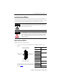
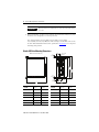
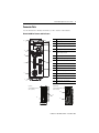
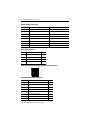
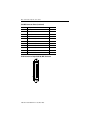
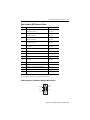
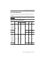
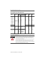
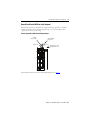
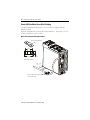
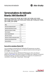
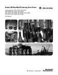
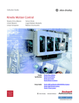
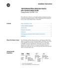
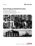
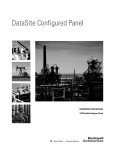
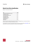
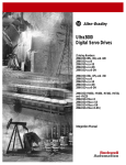
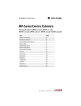
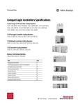
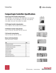
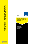
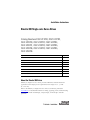
Installation Instructions Kinetix 300 Single-axis Servo Drives Catalog Numbers 2097-V31PR0, 2097-V31PR2, 2097-V32PR0, 2097-V32PR2, 2097-V32PR4, 2097-V33PR1, 2097-V33PR3, 2097-V33PR5, 2097-V33PR6, 2097-V34PR3, 2097-V34PR5, 2097-V34PR6 Topic Page About the Kinetix 300 Drives 1 Important User Information 2 Catalog Number Explanation 3 Before You Begin 4 Install the Kinetix 300 Drive 5 Connector Data 7 Power Wiring Requirements 13 Additional Resources 17 About the Kinetix 300 Drives Kinetix 300 single-axis servo drives provide an Ethernet enabled solution for applications with output power requirements in the range of 0.4…3.0 kW (2…12 A rms). Refer to the Kinetix 300 Single-axis Servo Drive User Manual, publication 2097-UM001, for detailed information on wiring, applying power, troubleshooting, and integration with ControlLogix, CompactLogix, or MicroLogix controller platforms. 2 Kinetix 300 Single-axis Servo Drives Important User Information Solid state equipment has operational characteristics differing from those of electromechanical equipment. Safety Guidelines for the Application, Installation and Maintenance of Solid State Controls (publication SGI-1.1 available from your local Rockwell Automation sales office or online at http://www.literature.rockwellautomation.com) describes some important differences between solid state equipment and hard-wired electromechanical devices. Because of this difference, and also because of the wide variety of uses for solid state equipment, all persons responsible for applying this equipment must satisfy themselves that each intended application of this equipment is acceptable. In no event will Rockwell Automation, Inc. be responsible or liable for indirect or consequential damages resulting from the use or application of this equipment. The examples and diagrams in this manual are included solely for illustrative purposes. Because of the many variables and requirements associated with any particular installation, Rockwell Automation, Inc. cannot assume responsibility or liability for actual use based on the examples and diagrams. No patent liability is assumed by Rockwell Automation, Inc. with respect to use of information, circuits, equipment, or software described in this manual. Reproduction of the contents of this manual, in whole or in part, without written permission of Rockwell Automation, Inc., is prohibited. Throughout this manual, when necessary, we use notes to make you aware of safety considerations. WARNING IMPORTANT ATTENTION Identifies information about practices or circumstances that can cause an explosion in a hazardous environment, which may lead to personal injury or death, property damage, or economic loss. Identifies information that is critical for successful application and understanding of the product. Identifies information about practices or circumstances that can lead to personal injury or death, property damage, or economic loss. Attentions help you identify a hazard, avoid a hazard and recognize the consequences. SHOCK HAZARD Labels may be on or inside the equipment, for example, a drive or motor, to alert people that dangerous voltage may be present. BURN HAZARD Labels may be on or inside the equipment, for example, a drive or motor, to alert people that surfaces may reach dangerous temperatures. Publication 2097-IN001B-EN-P - December 2009 Kinetix 300 Single-axis Servo Drives 3 Catalog Number Explanation This publication applies to the following Kinetix 300 drives. Kinetix 300 Drive Catalog Numbers Cat. No. Single-axis Servo Drive (120/240V) 2097-V31PR0 Kinetix 300,120/240V AC, 1 Ø, 2.0 A 2097-V31PR2 Kinetix 300, 120/240V AC, 1 Ø, 4.0 A 2097-V32PR0 Kinetix 300, 240V AC,1 Ø, 2.0 A, with integrated filter 2097-V32PR2 Kinetix 300, 240V AC, 1 Ø, 4.0 A, with integrated filter 2097-V32PR4 Kinetix 300, 240V AC, 1 Ø, 8.0 A, with integrated filter 2097-V33PR1 Kinetix 300, 240V AC, 1 Ø or 3 Ø, 2.0 A 2097-V33PR3 Kinetix 300, 240V AC, 1 Ø or 3 Ø, 4.0 A 2097-V33PR5 Kinetix 300, 240V AC, 1 Ø or 3 Ø, 8.0 A 2097-V33PR6 Kinetix 300, 240V AC, 1 Ø or 3 Ø, 12.0A 2097-V34PR3 Kinetix 300, 480V AC, 3 Ø, 2.0 A 2097-V34PR5 Kinetix 300, 480V AC, 3 Ø, 4.0 A 2097-V34PR6 Kinetix 300, 480V AC, 3 Ø, 6.0 A Single-axis Servo Drive (240V) Single-axis Servo Drive (480V) Publication 2097-IN001B-EN-P - December 2009 4 Kinetix 300 Single-axis Servo Drives Before You Begin Remove all packing material, wedges, and braces from within and around the components. After unpacking, check the item nameplate catalog number against the purchase order. Parts List The Kinetix 300 drive ships with: general purpose power input (IPD) header, back-up power (BP) header, shunt resistor and DC bus (BC) header, motor power (MP) header, and safe torque off (STO) header. a ground clamp that also provides strain relief for motor power cable. these installation instructions, publication 2097-IN001. TIP Connector kit for motor feedback (catalog number 2090-K2CK-D15M) is not provided. Replacement connector sets (catalog number 2097-CONN1), as described in the Parts List, are also available. Refer to the Kinetix Motion Control Selection Guide, publication GMC-SG001, for more information on connector kits and replacement connector sets. Publication 2097-IN001B-EN-P - December 2009 Kinetix 300 Single-axis Servo Drives 5 Install the Kinetix 300 Drive These procedures assume you have prepared your panel, and understand how to bond your system. For installation instructions regarding equipment and accessories not included here, refer to the instructions that came with those products. SHOCK HAZARD ATTENTION To avoid hazard of electrical shock, perform all mounting and wiring of the Kinetix 300 drive prior to applying power. Once power is applied, connector terminals may have voltage present even when not in use. Plan the installation of your system so that you can perform all cutting, drilling, tapping, and welding with the system removed from the enclosure. Because the system is of the open type construction, be careful to keep any metal debris from falling into it. Metal debris or other foreign matter can become lodged in the circuitry, which can result in damage to components. Mount the Kinetix 300 Drive Follow these steps to mount the drive. 1. Observe these clearance requirements when mounting the drive to the panel. 25.0 mm (1.0 in.) Clearance for airflow and installation. Drive 2097-V31PR0 2097-V31PR2 Allow 3 mm (0.12 in.) Side Clearance Allow 3 mm (0.12 in.) Side Clearance Cabinet Depth, min mm (in.) 332 (13) 2097-V32PR0 2097-V32PR2 377 (15) 2097-V32PR4 2097-V33PR1 2097-V33PR3 25.0 mm (1.0 in.) Clearance for airflow and Installation 332 (13) (1) 2097-V33PR5 2097-V33PR6 2097-V34PR3 Allow additional space for side mount or rear mount AC line filters. 2097-V34PR5 See the table and Kinetix 300 AC Line Filter Installation Instructions, publication 2097-IN003. 2097-V34PR6 (1) 377 (15) 332 (13) (1) 377 (15) If using an AC line filter, add 50 mm (2 in.) Publication 2097-IN001B-EN-P - December 2009 6 Kinetix 300 Single-axis Servo Drives Mount the module in an upright position as shown. Do not mount the module on its side. IMPORTANT 2. Mount the Kinetix 300 drive to the cabinet sub-panel with a M4 (#6-32) steel machine screw torqued to 1.1 N•m (9.8 lb•in). For catalog numbers 2097-V33PR1, 2097-V33PR3, 2097-V33PR5, 2097-V34PR3, and 2097-V34PR5 that will be using a AC line filter, refer to the AC Line Filter Installation Instructions, publication 2097-IN003, for sub-panel mounting hole pattern. Kinetix 300 Drive Mounting Dimensions Dimensions are in mm (in.). 7.1 (0.28) dia = 4.57 (0.18) 30.8 (1.21) 182.4 (7.18) 190.5 (7.50) 6.6 (0.26) 11.8 (0.46) A 38.1 (1.5) 4.57 (0.18) B Cat. No. A mm (in.) B mm (in.) Cat. No. A mm (in.) B mm (in.) 2097-V31PR0 185.1 (7.29) 68.0 (2.68) 2097-V33PR3 185.1 (7.29) 68.5 (2.70) 2097-V31PR2 185.1 (7.29) 68.5 (2.70) 2097-V33PR5 185.1 (7.29) 94.4 (3.72) 2097-V32PR0 229.6 (9.04) 68.0 (2.68) 2097-V33PR6 229.6 (9.04) 68.0 (2.68) 2097-V32PR2 229.6 (9.04) 68.5 (2.70) 2097-V34PR3 185.1 (7.29) 68.5 (2.70) 2097-V32PR4 229.6 (9.04) 86.8 (3.42) 2097-V34PR5 185.1 (7.29) 94.4 (3.72) 2097-V33PR1 185.1 (7.29) 68.0 (2.68) 2097-V34PR6 229.6 (9.04) 68.0 (2.68) Publication 2097-IN001B-EN-P - December 2009 Kinetix 300 Single-axis Servo Drives 7 Connector Data Use this illustration to identify the Kinetix 300 drive features and indicators. Kinetix 300 Drive Features and Indicators 12 1 2 11 3 10 4 9 5 8 7 6 Top View (2097-V33PR5 Kinetix 300 drive is shown) Item Description 1 Ground lug 2 Status and diagnostic display 3 Display control push buttons (3) 4 Back-up power (BP) connector 5 Shunt resistor and DC bus (BC) connector 6 Ground lug 7 Bottom mounting flange 8 Motor feedback (MF) connector 9 I/O (IOD) connector 10 Ethernet communication port (Port 1) 11 Memory module 12 Top mounting flange 13 Mains (IPD) connector 14 Motor power (MP) connector 15 Safe torque off (STO) connector 16 Heat sink (on some models) Bottom View (2097-V33PR5 Kinetix 300 drive is shown) 14 16 13 15 Publication 2097-IN001B-EN-P - December 2009 8 Kinetix 300 Single-axis Servo Drives Kinetix 300 Drive Connectors Designator Description Connector IPD AC mains input power 4-position plug/header PORT1 Ethernet communication port RJ45 Ethernet (2) IOD I/O SCSI 50 pin high density connector MF Motor feedback 15-pin high-density D-shell (male) BP Back-up power 2-pin quick-connect terminal block BC Brake resistor and DC bus 5-pin quick-connect terminal block MP Motor power 6-pin quick-connect terminal block STO Safe torque off (STO) terminal 6-pin quick-connect terminal block Mains (IPD) Connector IPD Pin Description Signal 1 Protective earth (ground) PE 2 AC power in L1 3 AC power in L2 4 AC power in (3 phase models) L3 Pin Orientation for 8-pin Ethernet Communication Port (port 1) 1 8 Ethernet Communication Port (port 1) Port 1 Pin Description Signal 1 Transmit port (+) data terminal + TX 2 Transmit port (-) data terminal - TX 3 Receive port (+) data terminal + RX 4 — — 5 — — 6 Receive port (-) data terminal - RX 7 — — 8 — — Publication 2097-IN001B-EN-P - December 2009 Kinetix 300 Single-axis Servo Drives 9 I/O (IOD) Connector Pinout IOD Pin Description Signal 1 Master encoder A+/Step+ input MA+ 2 Master encoder A-/Step- input MA- 3 Master encoder B+/Direction+ input MB+ 4 Master encoder B-/Direction- input MB- 5 Drive logic common GND 6 +5V DC Output (max 100 mA) 5V DC 7 Buffered encoder output: channel A+ BA+ 8 Buffered encoder output: channel A- BA- 9 Buffered encoder output: channel B+ BB+ 10 Buffered encoder output: channel B- BB- 11 Buffered encoder output: channel Z+ BZ+ 12 Buffered encoder output: channel Z- BZ- 13…21 Reserved — 22 Analog common ACOM 23 Analog output (max 10 mA) AO 24 Positive (+) of analog signal input AIN1+ 25 Negative (-) of analog signal input AIN1- 26 Digital input group ACOM terminal IN_A_COM 27 Digital input A1 IN_A1 28 Digital input A2 IN_A2 29 Digital input A3 IN_A3 30 Digital input A4 IN_A4 31 Digital input group BCOM terminal IN_B_COM 32 Digital input B1 IN_B1 33 Digital input B2 IN_B2 34 Digital input B3 IN_B3 35 Digital input B4 IN_B4 36 Digital input Group CCOM Terminal IN_C_COM 37 Digital input C1 IN_C1 38 Digital input C2 IN_C2 39 Digital input C3 IN_C3 Publication 2097-IN001B-EN-P - December 2009 10 Kinetix 300 Single-axis Servo Drives I/O (IOD) Connector Pinout (continued) IOD Pin Description Signal 40 Digital input C4 IN_C4 41 Ready output collector RDY+ 42 Ready output emitter RDY- 43 Programmable output #1 collector OUT1-C 44 Programmable output #1 emitter OUT1-E 45 Programmable output #2 collector OUT2-C 46 Programmable output #2 emitter OUT2-E 47 Programmable output #3 collector OUT3-C 48 Programmable output #3 emitter OUT3-E 49 Programmable output #4 collector OUT4-C 50 Programmable output #4 emitter OUT4-E Pin Orientation for 50-pin SCSI I/O (IOD) Connector 1 26 25 50 Publication 2097-IN001B-EN-P - December 2009 Kinetix 300 Single-axis Servo Drives 11 Motor Feedback (MF) Connector Pinout MF Pin Description Signal 1 Sine differential input+ AM+ Differential input+ MTR_SIN+ MTR_AM+ 2 Sine differential input- AM- Differential input- MTR_SIN- MTR_AM- 3 Cosine differential input+ BM+ Differential input+ MTR_COS+ MTR_BM+ 4 Cosine differential input- BM- Differential input- MTR_COS- MTR_BM- 5 Data differential input + Index pulse+ MTR_DATA+ MTR_IM+ 6 Common MTR_ECOM 7 Encoder power (+9V) MTR_EPWR_9V (1) 8 Single-ended 5V Hall effect commutation MTR_S3 9 Reserved — 10 Data differential input - Index pulse- MTR_DATA- MTR_IM- 11 Motor thermal switch (normally closed) (2) MTR_TS 12 Single-ended 5V Hall effect commutation MTR_S1 13 Single-ended 5V Hall effect commutation MTR_S2 14 Encoder power (+5V) MTR_EPWR_5V (1) 15 Reserved — (1) Encoder power supply uses either 5V or 9V DC based on encoder/motor used. (2) Not applicable unless motor has integrated thermal protection. Pin Orientation for 15-pin Motor Feedback (MF) Connector Pin 15 Pin 11 Pin 6 Pin 10 Pin 5 Pin 1 Publication 2097-IN001B-EN-P - December 2009 12 Kinetix 300 Single-axis Servo Drives Control Power Back-up (BP) Pinout BP Pin Description Signal 1 Positive 24V DC +24V DC 2 24V DC power supply return Return Shunt Resistor and DC Bus (BC) Pinout BC Pin Description Signal 1…2 Positive DC bus/brake resistor B+ 3 Brake resistor BR 4…5 Negative DC bus B- Motor Power (MP) Pinout MP Pin Description Signal 1 Motor power out U 2 Motor power out V 3 Motor power out W 4 Protective earth (ground) PE Safe Torque Off (STO) Pinout STO Pin Description Signal 1 +24V DC output from the drive +24V DC control 2 +24V DC output common Control COM 3 Safety status Safety Status 4 Safety input 1 (+24V DC to enable) Safety Input 1 5 Safety common Safety COM 6 Safety input 2 (+24V DC to enable) Safety Input 2 The Kinetix 300 drive ships with the safe torque off enabled. Connect the safe torque off inputs to a safety circuit or install motion allowed jumpers to obtain motion. Refer to the Kinetix 300 Single-axis Servo Drive User Manual, publication 2097-UM001, for details. Publication 2097-IN001B-EN-P - December 2009 Kinetix 300 Single-axis Servo Drives 13 Power Wiring Requirements Wire should be copper with 75 C (167 F) minimum rating. Phasing of main AC power is arbitrary and earth ground connection is required for safe and proper operation. IMPORTANT The National Electrical Code and local electrical codes take precedence over the values and methods provided. Kinetix 300 Drive Power Wiring Requirements Recommended Wire Size mm2 (AWG) Strip Length mm (in.) Torque Value N•m (lb•in) 2.5 (14) 7 (0.28) 0.5 (4.5) 2097-V32PR4 2097-V33PR5 4.0 (12) 7 (0.28) 0.5 (4.5) 2097-V31PR2 2097-V33PR6 6.0 (10) 7 (0.28) 0.56…0.79 (5.0…7.0) 2.5 (14) 7 (0.28) 0.5 (4.5) 4.0 (12) 7 (0.28) 0.5 (4.5) Terminals Cat. No. 2097-V31PR0 2097-V32PR0 2097-V32PR2 2097-V33PR1 2097-V33PR3 2097-V34PR3 2097-V34PR5 2097-V34PR6 2097-V31PR0 2097-V32PR0 2097-V32PR2 2097-V32PR4 2097-V33PR1 2097-V33PR3 2097-V33PR5 2097-V34PR3 2097-V34PR5 2097-V34PR6 2097-V31PR2 2097-V33PR6 Description Mains input power Motor power Pin IPD-1 IPD-2 IPD-3 IPD-4 MP-1 MP-2 MP-3 MP-4 Signal L3 L2 L1 PE PE W V U Publication 2097-IN001B-EN-P - December 2009 14 Kinetix 300 Single-axis Servo Drives Kinetix 300 Drive Power Wiring Requirements Terminals Cat. No. Description 2097-V31PR0 2097-V32PR0 2097-V32PR2 2097-V32PR4 2097-V33PR1 2097-V33PR3 2097-V33PR5 2097-V34PR3 2097-V34PR5 2097-V34PR6 2097-V31PR2 Brake resistor and DC bus(1) Pin BC-1 BC-2 BC-3 BC-4 BC-5 Signal B+ B+ BR B- B- 2097-V33PR6 2097-V3xPRx 2097-V3xPRx Control back-up power BP-1 BP-2 +24V DC Return Safe torque off STO-1 (2) STO-2 (2) STO-3 STO-4 STO-5 STO-6 +24V DC Control Control COM Safety Status Safety Input 1 Safety COM Safety Input 2 (1) Use for shunt resistor connection only. (2) Use for bypassing the STO circuit only. ATTENTION Recommended Wire Size mm2 (AWG) Strip Length mm (in.) Torque Value N•m (lb•in) 2.5 (14) 7 (0.28) 0.5 (4.5) 4.0 (12) 7 (0.28) 0.5 (4.5) 1.5 (16) 6 (0.25) 0.5 (4.5) To avoid personal injury and/or equipment damage, make sure installation complies with specifications regarding wire types, conductor sizes, branch circuit protection, and disconnect devices. The National Electrical Code (NEC) and local codes outline provisions for safely installing electrical equipment. To avoid personal injury and/or equipment damage, make sure motor power connectors are used for connection purposes only. Do not use them to turn the unit on and off. To avoid personal injury and/or equipment damage, make sure shielded power cables are grounded to prevent potentially high voltages on the shield. Publication 2097-IN001B-EN-P - December 2009 Kinetix 300 Single-axis Servo Drives 15 Ground Your Kinetix 300 Drive to the Subpanel If the Kinetix 300 drive is mounted on a painted subpanel, ground to a bonded cabinet ground bus using a braided ground strap or 4.0 mm2 (12 AWG) solid copper wire 100 mm (3.9 in.) long. Connecting the Braided Ground Strap Example Braided Ground Strap Ground Stud Bonded Cabinet Ground Bus Ground Grid or Power Distribution Ground For dimensions, Kinetix 300 Drive Mounting Dimensions on page 6. Publication 2097-IN001B-EN-P - December 2009 16 Kinetix 300 Single-axis Servo Drives Kinetix 300 Drive Motor Power Wire Shielding A motor power ground clamp and 2 #6-32 x 1 screws are supplied with the Kinetix 300 drive. Install the supplied motor power ground clamp within 100…150 mm (2…3 in.) of the drive using the 2 #6-32 x 1 screws. Motor Power Ground Clamp Installation Motor Power Ground Clamp 25 (1.0) 34.0 (1.34) 12.7 (0.50) Dimension are in mm (in.). 100…150 (2…3) If panel is painted, remove paint to provide metal-to-metal contact. Publication 2097-IN001B-EN-P - December 2009 Kinetix 300 Single-axis Servo Drives 17 Additional Resources These documents contain additional information concerning related Rockwell Automation products. Resource Description Kinetix 300 Single-axis Servo Drive User Manual, publication 2097-UM001 Information on installing, configuring, starting up, troubleshooting, and specifications for your Kinetix 300 servo drive system. Kinetix 300 Shunt Resistor Installation Instructions, publication 2097-IN002 Information on installing and wiring Kinetix 300 shunt resistors. Kinetix 300 AC Line Filter Installation Instructions, publication 2097-IN003 Information on installing and wiring the Kinetix 300 AC line filter. Kinetix 300 I/O Terminal Expansion Block Installation Instructions, publication 2097-IN005 Information on installing and wiring the Kinetix 300 I/O terminal expansion block. Kinetix 300 Memory Module Installation Instructions, publication 2097-IN007 Information on installing the Kinetix 300 memory module. Kinetix 300 Memory Module Programmer Quick Start, publication 2097-QS001 Information on using the memory module programmer to duplicate the memory module. 1769-L32E and 1769-L35E CompactLogix Controller Installation Instructions, publication 1769-IN020 Information on how to assemble and mount the controller, how to upgrade firmware, and controller technical specifications. 1769-L32C and 1769-L35CR CompactLogix Controller Installation Instructions, publication 1769-IN070 Information on how to assemble and mount the controller, how to upgrade firmware, and controller technical specifications. 1769-L31 CompactLogix Controller Installation Instructions, publication 1769-IN069 Information on how to assemble and mount the controller, how to upgrade firmware, and controller technical specifications. Industrial Automation Wiring and Grounding Guidelines, publication 1770-4.1 Provides general guidelines for installing a Rockwell Automation industrial system. Product Certifications website, http://ab.com Provides declarations of conformity, certificates, and other certification details. You can view or download publications at http://www.literature.rockwellautomation.com. To order paper copies of technical documentation, contact your local Rockwell Automation distributor or sales representative. Publication 2097-IN001B-EN-P - December 2009 18 Kinetix 300 Single-axis Servo Drives Notes: Publication 2097-IN001B-EN-P - December 2009 Kinetix 300 Single-axis Servo Drives 19 Notes: Publication 2097-IN001B-EN-P - December 2009 Rockwell Automation Support Rockwell Automation provides technical information on the Web to assist you in using its products. At http://www.support.rockwellautomation.com, you can find technical manuals, a knowledge base of FAQs, technical and application notes, sample code and links to software service packs, and a MySupport feature that you can customize to make the best use of these tools. For an additional level of technical phone support for installation, configuration and troubleshooting, we offer TechConnect support programs. For more information, contact your local distributor or Rockwell Automation representative, or visit http://www.support.rockwellautomation.com. Installation Assistance If you experience a problem within the first 24 hours of installation, please review the information that's contained in this manual. You can also contact a special Customer Support number for initial help in getting your product up and running. United States 1.440.646.3434 Monday – Friday, 8 a.m. – 5 p.m. EST Outside United States Please contact your local Rockwell Automation representative for any technical support issues. New Product Satisfaction Return Rockwell Automation tests all of its products to ensure that they are fully operational when shipped from the manufacturing facility. However, if your product is not functioning and needs to be returned, follow these procedures. United States Contact your distributor. You must provide a Customer Support case number (call the phone number above to obtain one) to your distributor in order to complete the return process. Outside United States Please contact your local Rockwell Automation representative for the return procedure. Allen-Bradley, Rockwell Automation, Rockwell Software, Kinetix, ControlLogix, CompactLogix, MicroLogix, and TechConnect are trademarks of Rockwell Automation, Inc. Trademarks not belonging to Rockwell Automation are property of their respective companies. Publication 2097-IN001B-EN-P - December 2009 Supersedes Publication 2097-IN001A-EN-P -December 2009 PN-57319 Copyright © 2009 Rockwell Automation, Inc. All rights reserved. Printed in the U.S.A.