1
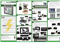
1
®
4
Unpack and Inspect
Inspect all equipment for completeness. If anything is missing or damaged,
immediately call the AutomationDirect® returns department
@ 1-800-633-0405.
p
3505 HUTCHINSON ROAD
CUMMING, GA 30040-5860
C-more EA9 Series Touch Panels
• Purchase the C-more programming software, EA9-PGMSW at
AutomationDirect.com. EA9-PGMSW is available on CD or by
direct download.
• Install EA9-PGMSW on your PC.
• Use the software to create a project.
• Download the project to the C-more panel from the software via
Ethernet or USB cable or on USB memory or SD card
Quick Start
Guide
Quick Start Guide
7
Install the Software and Develop a project
Cutout Template
• Access the Main Menu of the touch panel setup screens by pressing the extreme upper left
corner of the panel display area for three (3) seconds as shown below.
• Adjust the time and date for the panel by pressing the Setting button on the Main Menu,
then press the Adjust Clock button on the Setting screen.
• Use the right pointing arrows for the time or date display to select the unit to change. Use
the up and down arrows to increment or decrement the value for the selected unit.
• Press OK when done to accept the changes to the time and date that is retained in he
touch panel’s battery backed memory, or press Cancel to exit the Adjust Clock setup screen
without making any changes.
• Press the Main Menu button on the Setting screen and then the Exit button on the Main
Menu screen to return to the application screen.
Notes regarding Ethernet access to a C-more panel.
If you intend to take advantage of the methods of remote access to the panel, including the web server, PC remote
access, FTP, iPhone or iPad app, you need to consider the security exposure in order to minimize the risks to your
process and your C-more panel.
C-more Panel
Security measures may include password protection, changing the ports exposed on your network, including a VPN in
your network, and other methods. Security should always be carefully evaluated for each installation.
Gasket
Access the C-more Panel Setup Screens
DC power connector
5
Logo Label
Connect C-more Panel to Computer
• Connect a USB Programming Cable, such as p/n USB-CBL-AB15, from a USB type A
port on the PC to the USB type B programming port on the C-more touch panel
• or connect the C-more touch panel and PC together either directly or via an Ethernet
switch, and CAT5 Ethernet cables (full feature panels only)
Mounting Clips
C-more
Touch Panel
PC
USB
Port
USB
Port
USB-CBL-ABxx
USB Cable
USB
Stride™
Ethernet Switch
10/100 Base-T
PC
2
Ethernet
Port
Install Optional Hardware Accessories
Ethernet CAT5
Cable
WARNING: To minimize the risk of potential safety problems, you should follow
all applicable local and national codes that regulate the installation and operation of
your equipment. These codes vary from area to area and it is your responsibility to
determine which codes should be followed, and to verify that the equipment,
installation, and operation are in compliance with the latest revision of these codes.
Equipment damage or serious injury to personnel can result from the failure to follow
all applicable codes and standards. We do not guarantee the products described in this
publication are suitable for your particular application, nor do we assume any
responsibility for your product design, installation, or operation.
If you have any questions concerning the installation or operation of this
equipment, or if you need additional information, please call technical support at
1-800-633-0405 or 770-844-4200.
This publication is based on information available at the time it was printed. At
Automationdirect.com® we constantly strive to improve our products and services, so we
reserve the right to make changes to the products and/or publications at any time without
notice and without obligation. This publication may also discuss features that may not be
available in certain revisions of the product.
EA-x-COV2
Screen Protector
C-more
Touch Panel
Ethernet
Port
EA-SD-CARD
SD Card
C-more Touch Panel
Available Communication Ports
AC Wiring
Port 2
Port 1
Ethernet
C-more
Touch Panel
71 - 85 oz-in (0.5 - 0.6 Nm)
Mounting flange screw torque
57 - 71 oz-in (0.4 - 0.5 Nm)
DC-CON Tightening Torque
Power connector screw torque
SD Card Slot 1
Power connector mounting torque
DL06 PLC
Ethernet CAT5
Cable
SD Card Slot 2
Recommended AC Supply Fuse
3.0A time delay, ADC p/n: MDL3
56 oz-in (0.4 Nm)
Stride™
Ethernet Switch
10/100 Base-T
DC Wiring
0V
1
100 - 240 VAC
50 / 60 Hz
6
2
N.C.
3
RXD
4
TXD
Pin
5
+5V
1
N.C.
2
6
0V
2
D–
3
3
D+
4
GND
USB Port - Type B
Programming
Signal
12“ & 15”
G
4
HDMI Port Video Out
15
Pin
Signal
Pin
1
Pin
9
Signal
1
Frame GND
6
LE (for DH485)
11 TXD+ (422/485)
2
TXD (232C)
7
CTS (232C)
12 TXD– (422/485)
3
RXD (232C)
8
RTS (232C)
13 Term. Resistor
Signal
Pin
Signal
1
TD+
5
do not use
2
TD–
6
RD–
3
RD+
7
N.C.
4
do not use
8
N.C.
4
VCC
9
RXD+ (422/485)
14 N.C.
Link Status LED (Green)
5
Logic GND
10 RXD– (422/485)
15 N.C.
On
Pin
1 2 3 4
8
1
Vbus
2
D–
3
D+
4
GND
On
100M
Off No Ethernet Comm.
Off
10M
1
8
Watchdog Timer Error
GND
OS Error
Equipment
Ground
Power Loss Detection
Power LED (Front of Panel)
Additional Help and Support
NOTE: Use 60 / 75 °C copper conductors only,
12 - 24 AWG
Color
On
Off
Green
Power On
Power Error
Specification
Power Consumption
Internal Fuse
(non-replaceable)
EA9-T6CL-R
EA9-T6CL
16.0W
1.30A @ 12 VDC
0.66A @ 24 VDC
4.0A
• For product support, specifications, and installation troubleshooting, a Hardware User Manual
can be downloaded from the On-line Documentation area of the AutomationDirect Web site
• For software programming help, refer to the C-more Programming Software on-line embedded
help.
• Refer to demos of the product at: http://c-more.automationdirect.com/software/software_
demo.html
Power Specifications
Note: Device is not available on Base Feature touch panel EA9-T6CL-R
Note: Device is only available on touch panels EA9-T12CL and EA9-T15CL.
–
Memory Error
Model
Network Speed LED (Yellow)
Auto MDI / MDI-X
Ethernet Port
DL06 PLC
SHELL Shield
Ethernet Linked
Blinking Comm. Activity
Green
Signal
Ethernet CAT5
Cable
12-24 VDC
Normal - CPU Run State
Blinking Red
USB Port - Type A
USB Device Options
Ethernet 10/100 Base-T
PLC Communications,
Programming/Download
+
Power Off
Off
Blinking Green
Port 1
PLC Serial Communications
RS-232C / RS-485
MDL4
CPU Status LED (Green, Orange & Red)
Blinking Orange
Minimum items required to create a working system:
4.0 A
ADC p/n
MDL2-5
1
Red
Before you begin...
Panel Size Rating
6“ – 10”
2.5 A
C-more
Touch Panel
H0-ECOM/H0-ECOM100
Ethernet Module
Recommended DC Supply Fuse
N
Ethernet via
Switch
(such as SE-SW5U)
L
Signal
Auto MDI / MDI-X
Ethernet Port
70.4 oz-in (0.5 Nm)
Use 60 / 75°C copper conductors only, 12 - 24 AWG
Port 3
RJ12 Serial Communication
RS-232C
Signal
EA-2CBL-1
Power connector mounting torque 71 - 85 oz-in (0.5 - 0.6 Nm)
Logic Ground
Pin
DL-06 PLC
EA-AC Tightening Torque
Power supply cable torque
+
–
1
C-more
Touch Panel
Serial
H0-ECOM/H0-ECOMM100
Ethernet Module
Port 2
Serial Communication
RS-485
Pin
Connect the C-more Panel to a PAC or PLC
• Connect the serial communications cable between the C-more touch panel and the PLC
• or connect the C-more touch panel and PLC together via an Ethernet switch and Ethernet
cables (full feature panels only)
• or use an Ethernet cable directly between the C-more Ethernet port and the PLC Ethernet
port (full feature panels only)
Provide Power to C-more Panel
Green
Copyright 2014, Automationdirect.com Incorporated/All Rights Reserved Worldwide
Auto MDI / MDI-X
Ethernet Port
Wire a dedicated 12-24 VDC power source to the DC connector on the rear
of the C-more touch panel, include wiring the ground terminal to a proper
equipment ground. The recommended power supply is AutomationDirect
p/n: PSC24-060
• or install a C-more AC/DC Power Adapter, p/n EA-AC, to the rear of the touch panel and
wire an AC voltage source of 100-240 VAC, 50/60Hertz, to its AC connector
• then turn on the power source and check the LED status indicators on the front and rear
of the C-more touch panel for proper indication
USB-FLASH
USB Pen Drive
3
8
Ethernet CAT5
Cable
Ethernet
via Cable
6
Auto MDI / MDI-X
Ethernet Port
Ethernet
via Switch
PC
Shell Shield
• C-more EA9 Touch Panel - 6”, 8”, 10”, 12” or 15” model
• C-more Programming Software, p/n EA9-PGMSW
• Personal computer - to run the C-more programming software
• C-more USB Programming Cable, p/n USB-CBL-AB15 or Ethernet connectivity between PC
and Touch Panel
• Power source: C-more AC/DC Power Adapter, p/n EA-AC or a dedicated 12-24 VDC
switching power supply
• Communications Cable (serial or Ethernet) – to connect the C-more Touch Panel to your
controller
C-more
Touch Panel
EA-AC
AC / DC Power Adapter
Safety Information
ADVERTISSEMENT: Afin de réduire au minimum le risque d’éventuels problèmes de sécurité, vous devez respecter tous les codes locaux et nationaux applicables régissant l’installation
et le fonctionnement de votre équipement. Ces codes diffèrent d’une région à l’autre et,
habituellement, évoluent au fil du temps. Il vous incombe de déterminer les codes à respecter
et de vous assurer que l’équipement, l’installation et le fonctionnement sont conformes aux
exigences de la version la plus récente de ces codes.
L’omission de respecter la totalité des codes et des normes applicables peut entraîner des dommages
à l’équipement ou causer de graves blessures au personnel. Nous ne garantissons pas que les produits
décrits dans cette publication conviennent à votre application particulière et nous n’assumons
aucune responsabilité à l’égard de la conception, de l’installation ou du fonctionnement de votre
produit.
Si vous avez des questions au sujet de l’installation ou du fonctionnement de cet équipement,
ou encore si vous avez besoin de renseignements supplémentaires, n’hésitez pas à nous téléphoner au 770-844-4200.
Cette publication s’appuie sur l’information qui était disponible au moment de l’impression.
À la société AutomationDirect, nous nous efforçons constamment d’améliorer nos produits
et services. C’est pourquoi nous nous réservons le droit d’apporter des modifications aux
produits ou aux publications en tout temps, sans préavis ni quelque obligation que ce soit.
La présente publication peut aussi porter sur des caractéristiques susceptibles de ne pas être
offertes dans certaines versions révisées du produit.
(such as SE-SW5U)
EA9-T8CL
EA9-T10CL
EA9-T12CL
EA9-T15CL
18.0W
1.50A @ 12 VDC
0.75A @ 24 VDC
18.0W
1.50A @ 12 VDC
0.75A @ 24 VDC
21.0W
1.75A @ 12 VDC
0.88A @ 24 VDC
29.0W
2.40A @ 12 VDC
1.20A @ 24 VDC
• For additional technical support and questions, call our Technical Support team @
1-800-633-0405 or 770-844-4200.
6.3A
Data Sheet: EA9-QSG
Specifications
C-more Panel Dimensions
Specifications
Model
Specification
6” TFT color w/
base features
6” TFT color w/
full features
8” TFT color w/
full features
10” TFT color w/
full features
12” TFT color w/
full features
15” TFT color w/
full features
Part Number
EA9-T6CL-R
EA9-T6CL
EA9-T8CL
EA9-T10CL
EA9-T12CL
EA9-T15CL
5.7” TFT color
8.4” TFT color
10.4” TFT color
12.1” TFT color
15.0” TFT color
4.54” x 3.40”
[115.2 mm x 86.4 mm]
6.71” x 5.03”
[170.4 mm x127.8mm]
8.31” x 6.24”
[211.2 mm x 158.4 mm]
9.69” x 7.26”
[246.0 mm x 184.5 mm]
11.97” x 8.98”
[304.1 mm x 228.0 mm]
2.93 lb (1330g)
4.19 lb (1900g)
4.89 lb (2200g)
6.50 lb (2950g)
Display Actual Size and
Type
Display Viewing Area
Weight
1.56 lb (710g)
Screen Pixels
1.59 lb (720g)
320 x 240 (QVGA)
Display Brightness
LCD Panel Dot Pitch
800 x 600 (SVGA)
280 nits (typ)
310 nits (typ)
0.18 mm x 0.18 mm
0.213 mm x 0.213 mm
G
E
1024 x 768 (XGA)
F
0.264 mm x 0.264 mm
0.3075 mm x 0.3075 mm
Optional
EA-AC
0.297 mm x 0.297 mm
A
65,536 colors
Backlight Average
Lifetime*
50,000 hours @ 25 °C
Touch Panel Type
Four-wire analog resistive
26 MB
Number of Screens
Optional
EA-AC
280 nits (typ)
Color Scale
Project Memory
Panel Dimensions
C
Model
Number
A
B
C
D
E
F
G
EA9-T6CL-R
8.08
[205.2]
6.13
[155.8]
7.40
[188.0]
5.46
[138.7]
1.58
[40.1]
0.32
[8.1]
2.99
[75.9]
EA9-T6CL
8.08
[205.2]
6.13
[155.8]
7.40
[188.0]
5.46
[138.7]
1.58
[40.1]
0.32
[8.1]
2.99
[75.9]
EA9-T8CL
9.87
[250.7]
7.69
[195.4]
9.19
[233.4]
7.01
[178.1]
2.09
[53.1]
0.32
[8.1]
3.51
[89.2]
EA9-T10CL
12.52
[318.0]
9.53
[242.1]
11.84
[300.7]
8.84
[224.5]
1.93
[49.0]
0.32
[8.1]
3.51
[89.2]
EA9-T12CL
13.37
[339.6]
11.02
[280.0]
12.52
[318.0]
10.17
[258.3]
1.93
[49.0]
0.32
[8.1]
3.35
[85.1]
EA9-T15CL
15.75
[400.0]
12.09
[307.2]
14.88
[378.0]
11.20
[284.5]
1.93
[49.0]
0.32
[8.1]
3.35
[85.1]
Units: Inches [mm]
82 MB
Up to 999 screens – limited by project memory
Realtime Clock
Realtime Clock Built into panel, backed up for 30 days at 25°C
Calendar Month / Day / Year
Yes - monthly deviation 60 sec (Reference)
Serial Port 1
15-pin D-sub female - RS232C, RS-422/485
Serial Port 2
N/A
3-wire terminal block - RS-485
Serial Port 3
N/A
RJ-12 modular jack - RS-232C
USB Port - Type B
USB 2.0 High speed (480 Mbps) Type B - Download/Program
USB Port - Type A
USB 2.0 High speed (480 Mbps) Type A -for USB device options
D
B
Ethernet Port
N/A
Ethernet Port Ethernet 10/100 Base-T, auto MDI/MDI-X
Audio Line Out
N/A
3.5 mm mini jack – requires amplifier and speaker(s)
Mic In
N/A
3.5 mm mini jack
SD Card Slot
1 slot supports max 2 GB (SD,) max 32 GB (SDHC)
2 slots support max 2 GB (SD,) max 32 GB (SDHC)
N/A
Yes
HDMI Out
12-24 VDC, or use the AC/DC Power Adapter, EA-AC, to power the touch panel from a 100-240 VAC, 50/60 Hz power source.
Reverse Polarity Protected
Supply Power
16.0W
1.30A @ 12 VDC
0.66A @ 24 VDC
Power Consumption
Internal Fuse
(non-replaceable)
18.0W
1.50A @ 12 VDC
0.75A @ 24 VDC
18.0W
1.50A @ 12 VDC
0.75A @ 24 VDC
4.0A
21.0W
1.75A @ 12 VDC
0.88A @ 24 VDC
29.0W
2.40A @ 12 VDC
1.20A @ 24 VDC
C-more Panel Mounting
Cutout Dimensions
6.3A
A
D
0 to 50 °C (32 to 122 °F); Maximum surrounding air temperature rating: 50 °C (122 °F)
IEC 60068-2-14 (Test Nb, Thermal Shock)
Operating Temperature
J J
–20 to +60 °C (–4 to +140 °F)
IEC 60068-2-1 (Test Ab, Cold)
IEC 60068-2-2 (Test Bb, Dry Heat)
IEC 60068-2-14 (Test Na, Thermal Shock)
Storage Temperature
Humidity
Model
Number
A
B
D
E
J
EA9-T6CL-R
8.08
[205.2]
6.13
[155.8]
7.46
[189.5]
5.51
[140.0]
0.31
[7.9]
EA9-T6CL
8.08
[205.2]
6.13
[155.8]
7.46
[189.5]
5.51
[140.0]
0.31
[7.9]
EA9-T8CL
9.87
[250.7]
7.69
[195.4]
9.25
[235.0]
7.07
[179.6]
0.31
[7.9]
EA9-T10CL
12.52
[318.0]
9.53
[242.1]
11.90
[302.3]
8.91
[226.3]
0.31
[7.9]
EA9-T12CL
13.37
[339.6]
11.02
[280.0]
12.57
[319.3]
10.22
[259.6]
0.40
[10.2]
EA9-T15CL
15.75
[400.0]
12.09
[307.2]
14.93
[379.2]
11.27
[286.3]
0.41
[10.4]
5–95% RH (non-condensing)
Environment
For use in Pollution Degree 2 environment, no corrosive gases permitted
Cutout
NEMA ICS3-304 ( EN61131-2 )
RFI, (145MHz, 440Mhz 10W @ 10cm)
Impulse 1000V @ 1mS pulse
EN61000-4-2 (ESD),
EN61000-4-3 (RFI)
EN61000-4-4 (FTB)
EN61000-4-5 (Serge)
EN61000-4-6 (Conducted)
EN61000-4-8 (Power frequency magnetic field immunity)
Noise Immunity
Withstand Voltage
E
B
Mounting Bracket
Locations
Cutout
1000 VAC, 1 min. (FG to Power supply )
Insulation Resistance
Units: Inches [mm]
> 10M ohm @ 500V DC (FG to Power supply )
Vibration
IEC60068-2-6 (Test Fc)
Shock
IEC60068-2-27 (Test Ea)
Emission
EN55011 Class A (Radiated RF emission)
Enclosure
NEMA 250 type 4/4X indoor use only
UL50 type 4X indoor use only
IP-65 indoor use only
(When mounted correctly)
Agency Approvals
UL508, E157382
CE (EN61131-2), RoHS (2011/65/EU)
CUL Canadian C22.2
* NOTE: The backlight average lifetime is defined as the average usage time it takes before the brightness becomes 50% of the initial brightness. The lifetime of the backlight depends on the ambient temperature. The lifetime will decrease under
low or high temperature usage.
UL Satisfaction Ratings
Model Number
EA9-T6CL-R
Outer edge front bezel
Additional Installation Information
• Clearance – The mounting clearances when installing the touch panel in an enclosure or cabinet shall be minimum of
4 inches from the top, bottom and sides and 1.72 inches from the rear.
• Derating – If EA9-T15CL is mounted off the vertical plane facing upward, the temperature shall be derated as shown
below. There is no derating if EA9-T15CL is mounted off the vertical plane facing downward. Other panels may be
mounted at any angle without derating consideration.
90°
EA9-T6CL, EA9-T6CL-R
and EA9-T8CL
(4 places)
90°
Angle: 45° - 90°
Temp: 0 - 50 °C
Angle: 15° - 90°
Temp: 0 - 50 °C
Input Ratings
45°
12 - 24 VDC, Class 2, Maximum 16.0W
EA9-T6CL
EA9-T8CL
12 - 24 VDC, Class 2, Maximum 18.0W
EA9-T10CL
EA9-T12CL
12 - 24 VDC, Class 2, Maximum 21.0W
EA9-T15CL
12 - 24 VDC, Class 2, Maximum 29.0W
Angle: 0° - 45°
Temp: 0 - 40 °C
15°
Terminal connecting wire size 12 - 24 AWG
Angle: 0° - 15°
Temp: 0 - 45 °C
Connecting torque 71 - 85 oz-in (5 - 7 lbf-in) (0.5 - 0.6 Nm)
Maximum surrounding air temperature rating, 50°C
0°
For use in Pollution Degree 2 environment
0°
All interface ports are intended to be directly connected to an isolated secondary circuit
For use on a flat surface of a type 4X Indoor Use Only enclosure
EA9-T15CL
EA9-T15CL
with EA-AC
EA9-T10CL
(8 places)
EA9-T12CL
and EA9-T15CL
(8 places)