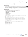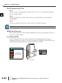
1
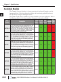
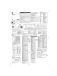
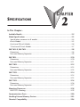
SPECIFICATIONS
CHAPTER
2
In This Chapter...
Available Models........................................................................................................ 2-2
Model Specifications ................................................................................................. 2-3
Specifications common to all models ....................................................................... 2-4
6-inch Models .......................................................................................................... 2-5
8-inch and 10-inch Models ...................................................................................... 2-6
12-inch and 15-inch Models .................................................................................... 2-7
EA9-T6CL-R, EA9-T6CL ............................................................................................... 2-8
Dimensions .............................................................................................................. 2-8
Ports and Memory Expansion ................................................................................... 2-9
EA9-T8CL .................................................................................................................. 2-10
Dimensions ............................................................................................................ 2-10
Ports and Memory Expansion ................................................................................. 2-11
EA9-T10CL ................................................................................................................ 2-12
Dimensions ............................................................................................................ 2-12
Ports and Memory Expansion ................................................................................. 2-13
EA9-T12CL ................................................................................................................ 2-14
Dimensions ............................................................................................................ 2-14
Ports and Memory Expansion ................................................................................. 2-15
EA9-T15CL ................................................................................................................ 2-16
Dimensions ............................................................................................................ 2-16
Ports and Memory Expansion ................................................................................. 2-17
Mounting Clearances .............................................................................................. 2-18
EA9-T15CL Derating ............................................................................................... 2-19
Communications Ports ............................................................................................ 2-20
Handling External Memory Devices ........................................................................ 2-23
Chemical Compatibility ........................................................................................... 2-26
Chapter 2 - Specifications
Available Models
1
2
3
4
5
6
7
8
9
10
11
12
13
14
A
B
C
D
The C-more® Operator Interface is the next generation of touch panel brought to you by
AutomationDirect. It has been designed to display and interchange graphical data from a
PLC by merely viewing or touching the screen.
The C-more Touch Panel is available in a variety of models to suit your application. Refer to
the following tables for a list of part numbers, descriptions and options available.
Part
Number
Description
C-more EA9 series touch screen interface panel, 6-inch color
TFT (5.7 inch viewable screen), base model, 64k colors, 320
x 240 pixel QVGA screen resolution, 800 MHz CPU, 12-24
powered, NEMA 4/4X, IP65 (when mounted correctly; for
EA9-T6CL-R VDC
indoor use only), non-replaceable LED backlight. Includes (1)
serial port, USB 2.0 Type A and B ports, supports SD memory
card, no Ethernet support. Compatible with EA9-PGMSW
programming software version 5.0 or later.
C-more EA9 series touch screen interface panel, 6-inch color
TFT (5.7 inch viewable screen), 64k colors, 320 x 240 pixel
QVGA screen resolution, 800 MHz CPU, 12-24 VDC powered,
4/4X, IP65 (when mounted correctly; for indoor use
EA9-T6CL NEMA
only), non-replaceable LED backlight. Includes (3) serial ports,
USB 2.0 Type A and B ports and Ethernet port; supports SD
memory card. Compatible with EA9-PGMSW programming
software version 5.0 or later.
C-more EA9 series touch screen interface panel, 8-inch color
TFT (8.4 inch viewable screen), 64k colors, 800 x 600 pixel
SVGA screen resolution, 800 MHz CPU, 12-24 VDC powered,
4/4X, IP65 (when mounted correctly; for indoor use
EA9-T8CL NEMA
only), non-replaceable LED backlight. Includes (3) serial ports,
USB 2.0 Type A and B ports and Ethernet port; supports SD
memory card. Compatible with EA9-PGMSW programming
software version 5.0 or later.
C-more EA9 series touch screen interface panel, 10-inch color
TFT (10.4 inch viewable screen), 64k colors, 800 x 600 pixel
SVGA screen resolution, 800 MHz CPU, 12-24 VDC powered,
4/4X, IP65 (when mounted correctly; for indoor use
EA9-T10CL NEMA
only), non-replaceable LED backlight. Includes (3) serial ports,
USB 2.0 Type A and B ports and Ethernet port; supports SD
memory card. Compatible with EA9-PGMSW programming
software version 5.0 or later.
C-more EA9 series touch screen interface panel, 12-inch color
TFT (12.1 inch viewable screen), 64k colors, 800 x 600 pixel
SVGA screen resolution, 800 MHz CPU, 12-24 VDC powered,
4/4X, IP65 (when mounted correctly; for indoor use
EA9-T12CL NEMA
only), non-replaceable LED backlight. Includes (3) serial ports,
USB 2.0 Type A and B ports and Ethernet port; supports (2)
SD memory cards. Includes HDMI video out. Compatible with
EA9-PGMSW programming software version 5.0 or later.
C-more EA9 series touch screen interface panel, 15-inch color
TFT (15 inch viewable screen), 64k colors, 1024 x 768 pixel
XGA screen resolution, 800 MHz CPU, 12-24 VDC powered,
4/4X, IP65 (when mounted correctly; for indoor use
EA9-T15CL NEMA
only), non-replaceable LED backlight. Includes (3) serial ports,
USB #2.0 Type A and B ports and Ethernet port; supports (2)
SD memory cards. Includes HDMI video out. Compatible with
EA9-PGMSW programming software version 5.0 or later.
2-2
®
HDMI
Project SD Card USB
Ethernet Video
Memory Option Device
Out
26 MB
1 slot
Yes
No
No
26 MB
1 slot
Yes
Yes
No
26 MB
1 slot
Yes
Yes
No
26 MB
1 slot
Yes
Yes
No
82 MB
2 slot
Yes
Yes
Yes
82 MB
2 slot
Yes
Yes
Yes
EA9-USER-M Hardware User Manual, 1st Ed. Rev. B 01/15
Chapter 2 - Specifications
Model Specifications
1
2
3
4
5
6
7
8
9
10
11
12
13
14
A
B
C
D
The following specification tables are separated into these groups:
• Specifications common to all models
• 6” Reduced and Full Feature Models, EA9-T6CL-R, and EA9-T6CL
• 8” & 10” Full Feature Models, EA9-T8CL and EA9-T10CL
• 12” & 15” Full Feature Models, EA9-T12CL & EA9-T15CL
Specification tables begin on the next page.
EA9-USER-M Hardware User Manual, 1st Ed. Rev. B 01/15
®
2-3
Chapter 2 - Specifications
Specifications common to all models
1
2
3
4
5
6
7
8
9
10
11
12
13
14
A
B
C
D
Model
Specification
All Models
0 to 50 °C (32 to 122 °F); Maximum surrounding air temperature rating: 50 °C (122 °F)
IEC 60068-2-14 (Test Nb, Thermal Shock)
–20 to +60 °C (–4 to +140 °F)
IEC 60068-2-1 (Test Ab, Cold)
IEC 60068-2-2 (Test Bb, Dry Heat)
IEC 60068-2-14 (Test Na, Thermal Shock)
5–95% RH (non-condensing)
For use in Pollution Degree 2 environment, no corrosive gases permitted
NEMA ICS3-304 ( EN61131-2 )
RFI, (145MHz, 440Mhz 10W @ 10cm)
Impulse 1000V @ 1mS pulse
EN61000-4-2 (ESD),
EN61000-4-3 (RFI)
EN61000-4-4 (FTB)
EN61000-4-5 (Serge)
EN61000-4-6 (Conducted)
EN61000-4-8 (Power frequency magnetic field immunity)
Operating Temperature
Storage Temperature
Humidity
Environment
Noise Immunity
Withstand Voltage
1000 VAC, 1 min. (FG to Power supply )
Insulation Resistance
> 10M ohm @ 500V DC (FG to Power supply )
Vibration
IEC60068-2-6 (Test Fc)
Shock
IEC60068-2-27 (Test Ea)
Emission
EN55011 Class A (Radiated RF emission)
Enclosure
NEMA 250 type 4/4X indoor use only
UL50 type 4X indoor use only
IP-65 indoor use only
(When mounted correctly)
Agency Approvals
UL508 (E157382), CE (EN61131-2), CUL Canadian C22.2, RoHS (2011/65/EU)
Backlight Average Lifetime*
Touch Panel Type**
Four-wire analog resistive
10.2-26.4 VDC Class 2, or use the AC/DC Power Adapter, EA-AC, to power the touch panel
from a 100-240 VAC, 50/60 Hz power source.
Reverse Polarity Protected
Supply Power
2-4
50,000 hours @ 25 °C
* NOTE: The backlight average lifetime is defined as the average usage time it takes before the brightness becomes
50% of the initial brightness. The lifetime of the backlight depends on the ambient temperature. The lifetime will
decrease under low or high temperature usage.
** NOTE: The Touchscreen is designed to respond to a single touch. If it is touched at multiple points at the same
time, an unexpected object may be activated.
®
EA9-USER-M Hardware User Manual, 1st Ed. Rev. B 01/15
Chapter 2 - Specifications
6-inch Models
Specification
Model
6” TFT color w/
base features
6” TFT color w/
full features
Part Number
EA9-T6CL-R
EA9-T6CL
Display Actual Size and Type
5.7” TFT color
4.54” x 3.40”
[115.2 mm x 86.4 mm]
Display Viewing Area
Weight
1.56 lb (710g)
Screen Pixels
1.59 lb (720g)
3200 x 240 (QVGA)
Display Brightness
280 nits (typ)
LCD Panel Dot Pitch
0.18 mm x 0.18 mm
Color Scale
65,536
Project Memory
26 MB
Number of Screens
Realtime Clock
Up to 999 screens – limited by project memory
Realtime Clock Built into panel, backed up for 30 days at 25°C
Calendar Month / Day / Year
Serial Port 1
Yes - monthly deviation 60 sec (Reference)
15-pin D-sub female - RS2342C, RS-422/485
Serial Port 2
N/A
3-wire terminal block - RS-485
Serial Port 3
N/A
RJ-12 modular jack - RS-232C
USB Port - Type B
USB 2.0 High speed (480 Mbps) Type B - Download/Program
USB Port - Type A
USB 2.0 High speed (480 Mbps) Type A -for USB device options
Ethernet Port
N/A
Audio Line Out
N/A
Ethernet Port Ethernet 10/100 Base-T, auto
MDI/MDI-X
3.5 mm mini jack – requires amplifier and
speaker(s)
Mic In
N/A
3.5 mm mini jack
SD Card Slot
1 slot. Supports max 2 GB (SD,) max 32 GB (SDHC)
HDMI Video Out
N/A
Power Consumption
Internal Fuse
(non-replaceable)
16.0W
1.30A @ 12 VDC
0.66A @ 24 VDC
4A
EA9-USER-M Hardware User Manual, 1st Ed. Rev. B 01/15
®
1
2
3
4
5
6
7
8
9
10
11
12
13
14
A
B
C
D
2-5
Chapter 2 - Specifications
8-inch and 10-inch Models
1
2
3
4
5
6
7
8
9
10
11
12
13
14
A
B
C
D
Specification
Model
8” TFT color w/
full features
10” TFT color w/
full features
Part Number
EA9-T8CL
EA9-T10CL
8.4” TFT color
10.4” TFT color
6.71” x 5.03”
[170.4 mm x127.8mm]
8.31” x 6.24”
[211.2 mm x 158.4 mm]
2.93 lb (1330g)
4.19 lb (1900g)
Display Actual Size and Type
Display Viewing Area
Weight
Screen Pixels
800 x 600 (SVGA)
Display Brightness
LCD Panel Dot Pitch
Color Scale
310 nits (typ)
280 nits (typ)
0.213 mm x 0.213 mm
0.264 mm x 0.264 mm
65,536 colors
Project Memory
26 MB
Number of Screens
Up to 999 screens – limited by project memory
Realtime Clock
Realtime Clock Built into panel, backed up for 30 days at 25°C
Calendar Month / Day / Year
Yes - monthly deviation 60 sec (Reference)
Serial Port 1
15-pin D-sub female - RS2342C, RS-422/485
Serial Port 2
3-wire terminal block - RS-485
Serial Port 3
RJ-12 modular jack - RS-232C
USB Port - Type B
USB 2.0 High speed (480 Mbps) Type B - Download/Program
USB Port - Type A
USB 2.0 High speed (480 Mbps) Type A -for USB device options
Ethernet Port
Ethernet Port Ethernet 10/100 Base-T, auto MDI/MDI-X
Audio Line Out
3.5 mm mini jack – requires amplifier and speaker(s)
Mic In
3.5 mm mini jack
SD Card Slot
1 slot. Supports max 2 GB (SD,) max 32 GB (SDHC)
HDMI Video Out
N/A
18.0W
1.50A @ 12 VDC
0.75A @ 24 VDC
Power Consumption
Internal Fuse
(non-replaceable)
2-6
6.3A
®
EA9-USER-M Hardware User Manual, 1st Ed. Rev. B 01/15
Chapter 2 - Specifications
12-inch and 15-inch Models
Specification
Model
12” TFT color w/
full features
15” TFT color w/
full features
Part Number
EA9-T12CL
EA9-T15CL
12.1” TFT color
15.0” TFT color
9.69” x 7.26”
[246.0 mm x 184.5 mm]
11.97” x 8.98”
[304.1 mm x 228.0 mm]
4.85 lb (2200g)
6.50 lb (2950g)
800 x 600 (SVGA)
1024 x 768 (XGA)
Display Actual Size and Type
Display Viewing Area
Weight
Screen Pixels
Display Brightness
LCD Panel Dot Pitch
280 nits (typ)
0.3075 mm x 0.3075 mm
Color Scale
0.297 mm x 0.297 mm
65,536 colors
Project Memory
82 MB
Number of Screens
Realtime Clock
Up to 999 screens – limited by project memory
Realtime Clock Built into panel, backed up for 30 days at 25°C
Calendar Month / Day / Year
Yes - monthly deviation 60 sec (Reference)
Serial PLC Interface Port 1
15-pin D-sub female - RS2342C, RS-422/485
Serial PLC Interface Port 2
3-wire terminal block - RS-485
Serial PLC Interface Port 3
RJ-12 modular jack - RS-232C
USB Port - Type B
USB 2.0 High speed (480 Mbps) Type B - Download/Program
USB Port - Type A
USB 2.0 High speed (480 Mbps) Type A -for USB device options
Ethernet Port
Ethernet Port Ethernet 10/100 Base-T, auto MDI/MDI-X
Audio Line Out
3.5 mm mini jack – requires amplifier and speaker(s)
Mic In
3.5 mm mini jack
SD Card Slot
2 slots. Supports max 2 GB (SD), max 32 GB (SDHC)
HDMI Video Out
HDMI Type A Port
HDMI Supported Resolution
800 x 600 (SVGA)
1024 x 768 (XGA)
Power Consumption
21.0W
1.75A @ 12 VDC
0.88A @ 24 VDC
29.0W
2.40A @ 12 VDC
1.20A @ 24 VDC
Internal Fuse
(non-replaceable)
6.3A
EA9-USER-M Hardware User Manual, 1st Ed. Rev. B 01/15
®
1
2
3
4
5
6
7
8
9
10
11
12
13
14
A
B
C
D
2-7
Chapter 2 - Specifications
EA9-T6CL-R, EA9-T6CL
1
2
3
4
5
6
7
8
9
10
11
12
13
14
A
B
C
D
2-8
Dimensions, Inches [mm]
All the necessary mounting hardware is provided with the touch panel. Use the four mounting
clips and screws to secure the touch panel to the cabinet or enclosure surface.
A template for marking the cutout dimensions on the mounting surface is provided in the box.
Enclosure Mounting Thickness Ranges
and Mounting Clip Screw Torque
Touch
Panel Size
6”, 8”, 10” and 12”
®
Enclosure
Mounting Clip
Thickness Range Screw Torque
0.039 - 0.20 inch
[1 – 5 mm]
63 - 77 oz-in
[0.45 - 0.55 Nm]
EA9-USER-M Hardware User Manual, 1st Ed. Rev. B 01/15
Chapter 2 - Specifications
Ports and Memory Expansion
EA9-T6CL-R
1
2
3
4
5
6
7
8
9
10
11
12
13
14
A
B
C
D
EA9-T6CL
EA9-USER-M Hardware User Manual, 1st Ed. Rev. B 01/15
®
2-9
Chapter 2 - Specifications
EA9-T8CL
1
2
3
4
5
6
7
8
9
10
11
12
13
14
A
B
C
D
2-10
Dimensions, Inches [mm]
All the necessary mounting hardware is provided with the touch panel. Use the four mounting
clips and screws to secure the touch panel to the cabinet or enclosure surface.
A template for marking the cutout dimensions on the mounting surface is provided in the box.
Enclosure Mounting Thickness Ranges
and Mounting Clip Screw Torque
Touch
Panel Size
6”, 8”, 10” and 12”
®
Enclosure
Mounting Clip
Thickness Range Screw Torque
0.039 - 0.20 inch
[1 – 5 mm]
63 - 77 oz-in
[0.45 - 0.55 Nm]
EA9-USER-M Hardware User Manual, 1st Ed. Rev. B 01/15
Chapter 2 - Specifications
Ports and Memory Expansion
EA9-T8CL
EA9-USER-M Hardware User Manual, 1st Ed. Rev. B 01/15
1
2
3
4
5
6
7
8
9
10
11
12
13
14
A
B
C
D
®
2-11
Chapter 2 - Specifications
EA9-T10CL
1
2
3
4
5
6
7
8
9
10
11
12
13
14
A
B
C
D
2-12
Dimensions, Inches [mm]
All the necessary mounting hardware is provided with the touch panel. Use the eight
mounting clips and screws to secure the touch panel to the cabinet or enclosure surface.
A template for marking the cutout dimensions on the mounting surface is provided in the box.
Enclosure Mounting Thickness Ranges
and Mounting Clip Screw Torque
Touch
Panel Size
6”, 8”, 10” and 12”
®
Enclosure
Mounting Clip
Thickness Range Screw Torque
0.039 - 0.20 inch
[1 – 5 mm]
63 - 77 oz-in
[0.45 - 0.55 Nm]
EA9-USER-M Hardware User Manual, 1st Ed. Rev. B 01/15
Chapter 2 - Specifications
Ports and Memory Expansion
EA9-T10CL
EA9-USER-M Hardware User Manual, 1st Ed. Rev. B 01/15
1
2
3
4
5
6
7
8
9
10
11
12
13
14
A
B
C
D
®
2-13
Chapter 2 - Specifications
EA9-T12CL
1
2
3
4
5
6
7
8
9
10
11
12
13
14
A
B
C
D
2-14
Dimensions, Inches [mm]
All the necessary mounting hardware is provided with the touch panel. Use the eight
mounting clips and screws to secure the touch panel to the cabinet or enclosure surface.
A template for marking the cutout dimensions on the mounting surface is provided in the box.
Enclosure Mounting Thickness Ranges
and Mounting Clip Screw Torque
Touch
Panel Size
6”, 8”, 10” and 12”
®
Enclosure
Mounting Clip
Thickness Range Screw Torque
0.039 - 0.20 inch
[1 – 5 mm]
63 - 77 oz-in
[0.45 - 0.55 Nm]
EA9-USER-M Hardware User Manual, 1st Ed. Rev. B 01/15
Chapter 2 - Specifications
Ports and Memory Expansion
EA9-T12CL
EA9-USER-M Hardware User Manual, 1st Ed. Rev. B 01/15
1
2
3
4
5
6
7
8
9
10
11
12
13
14
A
B
C
D
®
2-15
Chapter 2 - Specifications
EA9-T15CL
1
2
3
4
5
6
7
8
9
10
11
12
13
14
A
B
C
D
2-16
Dimensions, Inches [mm]
All the necessary mounting hardware is provided with the touch panel. Use the eight
mounting clips and screws to secure the touch panel to the cabinet or enclosure surface.
A template is provided for marking the cutout dimensions on the mounting surface.
Enclosure Mounting Thickness Ranges
and Mounting Clip Screw Torque
Touch
Panel Size
15”
®
Enclosure
Mounting Clip
Thickness Range Screw Torque
0.039 - 0.20 inch
[1 – 5 mm]
92 - 106 oz-in
[0.65 - 0.75 Nm]
EA9-USER-M Hardware User Manual, 1st Ed. Rev. B 01/15
Chapter 2 - Specifications
Ports and Memory Expansion
EA9-T15CL
EA9-USER-M Hardware User Manual, 1st Ed. Rev. B 01/15
1
2
3
4
5
6
7
8
9
10
11
12
13
14
A
B
C
D
®
2-17
Chapter 2 - Specifications
Mounting Clearances
1
2
3
4
5
6
7
8
9
10
11
12
13
14
A
B
C
D
2-18
The following drawing shows the mounting clearances for the C-more touch panel. There
should be a minimum of 4 inches of space between all sides of the panel and the nearest object
or obstruction and at least 1.72 inches between the rear of the panel and the nearest object or
obstruction.
Mounting Clip
4“ Min.
1.72“ Min.
4“ Min.
4“ Min.
4“ Min.
Front View
®
Air
Flow
Side View
EA9-USER-M Hardware User Manual, 1st Ed. Rev. B 01/15
Chapter 2 - Specifications
EA9-T15CL Derating
If EA9-T15CL is mounted off the vertical plane facing upward, the temperature shall be
derated as shown below. Other panels may be mounted at any angle without derating
consideration.
90°
EA9-T15CL
Angle: -15° to -90°
Temp: 0 to 50 °C
Angle: 15° to 90°
Temp: 0 to 50 °C
15°
Angle: 0° to 15°
Temp: 0 to 45 °C
Angle: 0° to -15°
Temp: 0 to 45 °C
0°
90°
Angle: -45° to 90°
Temp: 0 to 50 °C
EA9-T15CL
with EA-AC
Angle: 45° to 90°
Temp: 0 to 50 °C
45°
Angle: 0° to -45°
Temp: 0 to 40 °C
Angle: 0° to 45°
Temp: 0 to 40 °C
0°
0°
EA9-USER-M Hardware User Manual, 1st Ed. Rev. B 01/15
®
1
2
3
4
5
6
7
8
9
10
11
12
13
14
A
B
C
D
2-19
Chapter 2 - Specifications
Communications Ports
2-20
Port 2
Serial Communication
RS-485
+
–
Logic Ground
SD Card Slot 1
SD Card Slot 2
Port 3
RJ12 Serial Communication
RS-232C
Pin
Signal
1
0V
2
N.C.
3
RXD
1
6
USB Port - Type B
Programming
Pin
Signal
4
TXD
5
Supplies +5VDC
1
N.C.
2
1
6
0V
2
D–
3
4
3
D+
4
GND
Shell Shield
HDMI Port Video Out
Port 1
PLC Serial Communications
RS-232C / RS-485
Pin
Signal
Pin
Signal
8
1
15
9
Pin
Frame GND
6
LE (for DH485)
11 TXD+ (422/485)
2
TXD (232C)
7
CTS (232C)
12 TXD– (422/485)
3
RXD (232C)
8
RTS (232C)
13 Term. Resistor
4
VCC
(Supplies +5VDC)
9
RXD+ (422/485)
14 N.C.
5
Logic GND
10 RXD– (422/485)
15 N.C.
Pin
Signal
1
USB Port - Type A
USB Device Options
Ethernet 10/100 Base-T
PLC Communications,
Programming/Download
Signal
Pin
TD+
5
do not use
2
TD–
6
RD–
3
RD+
7
N.C.
4
do not use
8
N.C.
Link Status LED (Green)
On
Signal
1
Vbus
2
D–
3
D+
4
GND
SHELL Shield
Network Speed LED (Yellow)
Ethernet Linked
Off No Ethernet Comm.
Blinking Comm. Activity
Green
Pin
Signal
1
1 2 3 4
1
2
3
4
5
6
7
8
9
10
11
12
13
14
A
B
C
D
1
On
100M
Off
10M
8
Note: Device is not available on Base Feature touch panel EA9-T6CL-R
Note: Device is only available on touch panels EA9-T12CL and EA9-T15CL.
Ethernet Port
The Ethernet port can be used several ways: for programming the panel (downloading a
project), for PLC communication, and for the advanced features, such as sending e-mail, web
server, FTP access, and allowing users to access and control the panel remotely.
The Ethernet connector is an RJ-45 Module jack.
NOTE: EA9-T6CL-R does not include an Ethernet port and does not have these capabilities.
Refer to http://c-more.automationdirect.com for the latest driver information.
®
EA9-USER-M Hardware User Manual, 1st Ed. Rev. B 01/15
Chapter 2 - Specifications
Communications Ports (cont’d)
USB Type B Port
Program C-more via the USB programming port. It’s fast and easy, with no baud rate settings,
parity, or stop bits to worry about. We stock standard USB cables for your convenience,
such as part no. USB-CBL-AB15. The USB type B port can be used to upload or download
projects to and from a PC (personnel computer).
USB Type A Port
The USB type A port is a standard feature for all models and can be used to connect various
USB 2.0 HID (Human Input Device) devices to the panel, such as:
• USB pen drives, (ADC p/n USB-FLASH)
• USB keyboards
• USB barcode scanners
• USB card scanners
C-more can log data to the USB pen drive as well as restore projects to the panel from the pen
drive. You can also back up project files and panel firmware.
Sound Interface (Audio Line Out)
When attached to an amplifier and speaker(s), C-more can play warning sounds, or
pre-recorded messages such as: “conveyor is jammed”. Various “Objects” in the C-more
programming software support sounds. C-more supports WAV type files. Sound files are
stored in the sound library.
Audio WAV File Specifications
The C-more Audio Line Out port supports the following WAV file specifications:
Audio Format (codec): PCM
Audio Sample Rate: 44.1 kHz
Channels: 2 (stereo)
Audio Sample Size: 16-bit
EA9-USER-M Hardware User Manual, 1st Ed. Rev. B 01/15
®
1
2
3
4
5
6
7
8
9
10
11
12
13
14
A
B
C
D
2-21
Chapter 2 - Specifications
Serial Communication Ports
1
2
3
4
5
6
7
8
9
10
11
12
13
14
A
B
C
D
2-22
Port 1
Connect to your serial controller network via Port 1. Port 1 is a 15-pin port that supports
RS-232 and RS-422/485.
Port 2
Connect your RS-485 network via Port 2. Port 2 is provided with a 3-wire removable
terminal block.
Port 3
Connect to your RS-232C device via Port 3. Port 3 is an RJ12 connection
NOTE: EA9-T6CL-R does not include Serial Ports 2 and 3.
HDMI Port Video Out
EA9-T12CL and EA9-T15CL include an HDMI Type A port to provide video output to a
projector or remote monitor.
User Defined LED
The user defined LED on the panel front bezel can be controlled from the project to
illuminate red, green or orange. It can also be configured to blink these colors. Refer to the
online help file provided with the programming software for details.
User Defined LED (Green, Orange & Red)
Off
Power LED (Green)
Green
Red
Orange
Blinking
Red
Blinking
Orange
Blinking
Green
User Defined
(Refer to online help
file for further details)
On
Power On
Off
Power Off
Front View
®
EA9-USER-M Hardware User Manual, 1st Ed. Rev. B 01/15
Chapter 2 - Specifications
Handling External Memory Devices
Consider the following to minimize the risk of data error when utilizing data logging.
• Do not turn off power to the C-more touch panel at any time the external memory device is being
accessed.
• Do not remove any external memory device when the device is being accessed by the touch panel.
NOTE: A system tag, such as SYS %device% WriteStatus can be used to detect when the external memory device
is being accessed. See the C-more programming software on-line help for additional information on System Tag
Names.
• If an SD memory card is plugged into the SD card slot while the panel is running, the project will
continue to run from the project that is currently in the internal SDRAM. If power is cycled and
there is a good project stored on the SD memory card, then that project will overwrite the internal
SDRAM and run.
• Be sure to backup the memory device at regular intervals.
• An SD memory card plugged into the SD card slot that includes a project that is being run cannot
be used for backup.
• If you suspect the memory device is bad, you may want to use a PC to re-format the device, or use a
known good memory device.
NOTE: The C-more touch panel requires that all external memory devices be formatted with a FAT or FAT32 file
system.
NOTE: SD cards must be formatted using the SD formatter provided by the SD Association at sdcard.org.
SD cards up to 2GB capacity must be formatted FAT. SDHC cards up to 32 GB must be formatted FAT32.
USB memory must be formatted FAT or FAT32.
• The number of times the memory device can be written to is limited, approximately 300,000 times.
Consequently, frequent writing at short intervals may shorten the service life of the memory device.
Try to use as long as possible sampling times for logging data to reduce the amount of times the
memory device is accessed.
• USB mouse (on-screen mouse pointer is enabled via System Screen setup or Panel Manager)
EA9-USER-M Hardware User Manual, 1st Ed. Rev. B 01/15
®
1
2
3
4
5
6
7
8
9
10
11
12
13
14
A
B
C
D
2-23
Chapter 2 - Specifications
1
2
3
4
5
6
7
8
9
10
11
12
13
14
A
B
C
D
2-24
Different types of numeric and text data from the C-more touch panel can be stored on an
SD card or a USB memory device. Numeric data from Line Trend Graph and PID Faceplate
Trend Graph objects may be stored. Text data from Lookup Text and Multi-state Text
objects can also be stored. Up to 16 objects may be configured in the C-more programming
software to log data. Along with the 16 object limit, available storage on the external memory
device is subject to the memory capacity of the SD card or USB memory device. One log
file is created in a 24 hour period for each object. Additionally log file data is written to the
external memory device:
• when 2kB of data is cached,
• when 20 records have been stored,
• periodically, once every 1 minute,
• when one of the internal “copy logTo” or “Eject” tags is activated via an object or event,
• when there is an email or FTP action
• when the System Screen is called
• when the panel date is changed
®
EA9-USER-M Hardware User Manual, 1st Ed. Rev. B 01/15
Chapter 2 - Specifications
File Name Limitations
There is a limit of 999 file names with the same first four characters. Internal file names
are restricted by the DOS 8-character-dot-3-character limit. Therefore trend log files are
identified internally by the first four characters of the object name plus tilde plus a three digit
number. Examples are:
TREND GRAPH EAST CHILLER TEMP_130925.txt saved internally as TREN~001.txt
TREND GRAPH WEST CHILLER TEMP_130925.txt saved internally as TREN~002.txt
As new log files are created in each 24 hour period, these files count against the maximum of
999 files. If multiple graph objects appear on one screen, the files will be identified internally
by the first Two Characters of the screen name plus the first Two Characters of the object
name plus tilde plus three digit number. To maximize storage capabilities on external memory
devices use screen names that have unique characters in the first four digits and object names
that are unique in the first two characters.
NOTE: When the 999 filename limit is reached, the oldest files will automatically be deleted and logging will
continue.
Monitoring Available Memory
External memory device memory can be monitored and events can be configured to alert the
user when available memory is approaching the maximum capacity of the external memory
device. The following internal tags allow external memory device data to be available:
• SYS SD1 TOTALMEMORY
• SYS SD1 FREEMEMORY
• SYS SD1 USEDMEMORY
• SYS SD2 TOTALMEMORY
• SYS SD2 FREEMEMORY
• SYS SD2 USEDMEMORY
• SYS USB TOTALMEMORY
• SYS USB FREEMEMORY
• SYS USB USEDMEMORY
Refer to the C-more programming software online help files for additional information on
system tags and managing data logging devices.
EA9-USER-M Hardware User Manual, 1st Ed. Rev. B 01/15
®
1
2
3
4
5
6
7
8
9
10
11
12
13
14
A
B
C
D
2-25
Chapter 2 - Specifications
Minimizing Data Errors
To minimize data errors when logging data to external memory, consider the following:
1
• Do not turn off power to the C-more touch panel while the external memory device is being
accessed. The optional EA-AC power adaptor is designed to protect external memory devices from
damage during power failure.
2
• Do not remove any external memory device with the device is being accessed by the C-more panel.
The following internal tags should be used to monitor, access and safely remove external memory
3
devices:
• SYS SD1 WriteStatus
4
• SYS SD2 WriteStatus
• SYS USB WriteStatus
5
• SYS Copy LogToSD1
• SYS Copy LogToSD2
6
• SYS Copy LogToUSB
• SYS SD1 Eject
7
• SYS SD2 Eject
• SYS USB Eject
8
• SYS SD1 ReadyToUse
• SYS SD2 ReadyToUse
9
• SYS USB ReadyToUse
Refer to the C-more programming software online help files for additional information on
10
system tags and managing data logging devices.
11 Chemical Compatibility
The C-more touch panels comprise three different materials that may be exposed to outside
12
elements: a gasket, a screen sheet and a bezel.
• Gasket material is silicone.
13
• Screen sheets are PET.
• Panel bezels are ABS plastic.
14
A
B
C
D
2-26
®
EA9-USER-M Hardware User Manual, 1st Ed. Rev. B 01/15