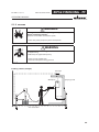
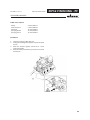
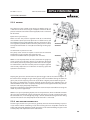
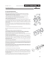
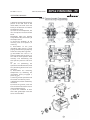
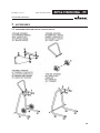
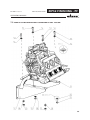
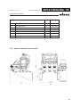
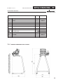
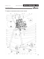
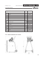
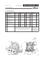
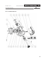
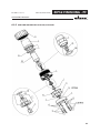
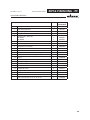
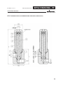
1
Translation of the original Operating Manual ZIP52 ALU SP ZIP 52 INOX SP ZIP 52 ACETAL SP ZIP 52 PERFECT FLOW SP Edition 01 / 2010 Diaphragms pump ZIP 52 FINISHING ZIP 52 PF II 2G IIB T4 EDITION 01 /2010 PART NO. ZZB012ENG ZIP52 FINISHING - PF . OPERATING MANUAL Contents 1 1.1 1.2 ABOUT THESE INSTRUCTIONS Languages Warnings, notes and symbols in these instructions 5 5 5 2 2.1 2.1.1 2.1.2 2.1.3 2.2 2.2.1 2.2.2 2.2.3 2.2.4 2.2.5 2.2.6 2.3 2.4 2.4.1 2.4.2 2.4.3 2.4.4 GENERAL SAFETY INSTRUCTIONS Safety instructions for the operator Electrical equipment Personnel qualifications A safe work environment Safety instructions for staff Safe handling of WAGNER spray units Earth the unit Material hoses Cleaning Handling hazardous liquids, varnishes and paints Touching hot surfaces Correct use Use in an explosion hazard area Correct use Explosion protection identification Max. surface temperature Safety regulations 6 6 6 6 6 6 7 7 7 8 8 8 8 9 9 9 9 9 3 3.1 3.2 3.3 3.4 3.5 3.6 PRODUCT LIABILITY AND WARRANTY Scope of guarantee Guarantee period and registration (3+2) Handling Exclusion of guarantee Additional regulations CE-conformity 4 4.1 4.1.1 4.2 4.3 4.3.1 4.3.2 4.3.3 4.4 4.4.1 4.4.2 4.4.2.1 DESCRIPTION Field of application Using in accordance with the instructions Extent of delivery Data Materials of the parts transporting paint technical data Dimensions and connections Functioning Pump Pressure regulator Technical sheet fine flow controller cod. 2301832, 2301836, 2301837 14 14 14 14 14 14 15 16 18 18 19 20 5 5.1 5.1.1 5.1.2 5.2 STARTING UP AND OPERATING Installation and connection Pump installation Earthing Start up 21 21 21 22 24 (STATUS 01.02.2009) 11 11 11 11 12 12 13 3 EDITION 01 /2010 PART NO. ZZB012ENG ZIP52 FINISHING - PF . OPERATING MANUAL Contents 5.2.1 5.2.2 5.2.3 5.2.4 5.3 5.3.1 5.3.2 5.3.3 5.3.4 5.4 Safety regulations Emergency stopping Washing Unit pressure tightness test Work Spraying Painting hints Working breaks Shutting down and cleaning Storing for longer periods of time 24 25 26 26 27 27 28 28 29 29 6 6.1 6.2 6.3 6.4 FAULT LOCATION, MAINTENANCE AND REPAIR Trouble shooting and solution Maintenance Filter cleaning operations Machine maintenance 30 30 31 32 33 7 7.1 7.2 7.2.1 7.3 7.3.1 7.4 35 35 36 37 38 39 7.4.1 7.5 7.5.1 ACCESSORIES Accessories only for 2301832, 2301836, 2301837 Pump zip 52 finishing with wall supporting kit cod. T760.00M Overall dimensions cod. T760.00M Pump zip 52 finishing with stand kit cod. T760.00S Overall dimensions cod. T760.00S Pump zip 52 finishing with handle+wheels kit cod. T760.00R for stand pumps cod. T760.00S Overall dimensions cod. T760.00R Pompa zip 52 finishing with trolley kit cod. T760.00SR Overall dimensions cod. T760.00SR 8 8.1 8.2 8.3 8.3.1 8.3.2 8.3.3 8.3.4 8.3.5 8.3.6 8.3.7 SPARE PARTS How to order spare parts Overview modules Exploded view Pump cod. 2301832, 2301836, 2301837 Pump cod. 2301838 Pump ZIP 52 Air motor pump ZIP52 Fine flow controller T0180.00A, T0180.00AI Material filter 1/2 aluminium cod. T4005.00ALS (for 2301838) Suction pipe + re-cycle pipe cod. T406.00, T406.00A 44 44 46 47 47 50 53 55 57 59 61 9 EUROPEAN SERVICE NETWORK 65 40 41 42 43 4 EDITION 01 /2010 ZIP52 FINISHING - PF . PART NO. ZZB012ENG OPERATING MANUAL 1 ABOUT THESE INSTRUCTIONS 4HISOPERATINGMANUALCONTAINSINFORMATIONABOUTTHEOPERATIONREPAIRANDMAINTENANCE OFTHEUNIT !LWAYSFOLLOWTHESEINSTRUCTIONSWHENOPERATINGTHEUNIT 1.1 LANGUAGES 4HISOPERATINGMANUALISAVAILABLEINTHEFOLLOWINGLANGUAGES ,ANGUAGE 0ART.O ,ANGUAGE 'ERMAN ZZB012GER %NGLISH &RENCH ZZB012FRE $UTCH )TALIAN ZZB012ITA 3PANISH $ANISH -3WEDISH 0ORTUGUESE -4URKISH 1.2 0ART.O ZZB012ENG ----- WARNINGS, NOTES AND SYMBOLS IN THESE INSTRUCTIONS 7ARNINGINSTRUCTIONSINTHISMANUALPOINTOUTPARTICULARDANGERSTOUSERSANDEQUIPMENT ANDSTATEMEASURESFORAVOIDINGTHEHAZARD4HESEWARNINGINSTRUCTIONSFALLINTOTHEFOLLO WINGCATEGORIES $!.'%2 4HISLINEWARNSOFTHEHAZARD 0OSSIBLE CONSEQUENCES OF FAILING TO OBSERVE THE WARNING INSTRUC TIONS4HESIGNALWORDPOINTSOUTTHEHAZARDLEVEL $ANGERIMMINENTDANGER.ONOBSERVANCEWILLRESULT INDEATHSERIOUSINJURYANDSERIOUSMATERIALDAMAGE 3)()??'" 7ARNINGPOSSIBLEDANGER.ONOBSERVANCECANRESULT INDEATHSERIOUSINJURYANDSERIOUSMATERIALDAMAGE 7!2.).' 4HISLINEWARNSOFTHEHAZARD 0OSSIBLE CONSEQUENCES OF FAILING TO OBSERVE THE WARNING INSTRUC TIONS4HESIGNALWORDPOINTSOUTTHEHAZARDLEVEL 3)()??'" #AUTION A POSSIBLY HAZARDOUS SITUATION .ONOBSER VANCECANRESULTINMINORINJURY 4HEMEASURESFORPREVENTINGTHEHAZARDANDITSCONSEQUENCES 4HEMEASURESFORPREVENTINGTHEHAZARDANDITSCONSEQUENCES #!54)/. 4HISLINEWARNSOFTHEHAZARD 0OSSIBLE CONSEQUENCES OF FAILING TO OBSERVE THE WARNING INSTRUC TIONS4HESIGNALWORDPOINTSOUTTHEHAZARDLEVEL 4HEMEASURESFORPREVENTINGTHEHAZARDANDITSCONSEQUENCES 3)()??'" #AUTION A POSSIBLY HAZARDOUS SITUATION .ONOBSER VANCECANCAUSEMATERIALDAMAGE 3)()??'" #!54)/. 4HISLINEWARNSOFTHEHAZARD 0OSSIBLECONSEQUENCESOFFAILINGTOOBSERVETHEWARNINGINSTRUCTIONS4HESIGNALWORD POINTSOUTTHEHAZARDLEVEL 4HEMEASURESFORPREVENTINGTHEHAZARDANDITSCONSEQUENCES .OTEPROVIDEINFORMATIONONPARTICULARCHARACTERISTICSANDHOWTOPROCEED 5 EDITION 01 /2010 PART NO. ZZB012ENG ZIP52 FINISHING - PF . OPERATING MANUAL 2 GENERAL SAFETY INSTRUCTIONS 2.1 SAFETY INSTRUCTIONS FOR THE OPERATOR +EEPTHESEOPERATINGINSTRUCTIONSTOHANDNEARTHEUNITATALLTIMES !LWAYSFOLLOWLOCALREGULATIONSCONCERNINGOCCUPATIONALSAFETYANDACCIDENTPREVEN TION 2.1.1 ELECTRICAL EQUIPMENT %LECTRICALPLANTANDUNIT 4O BE PROVIDED IN ACCORDANCE WITH THE LOCAL SAFETY REQUIREMENTS WITH REGARD TO THE OPERATINGMODEANDAMBIENTINmUENCES -AYONLYBEMAINTAINEDBYSKILLEDELECTRICIANSORUNDERTHEIRSUPERVISION -USTBEOPERATEDINACCORDANCEWITHTHESAFETYREGULATIONSANDELECTROTECHNICALREGU LATIONS -USTBEREPAIREDIMMEDIATELYINTHEEVENTOFPROBLEMS -USTBEPUTOUTOFOPERATIONIFTHEYPOSEAHAZARD -USTBEDEENERGIZEDBEFOREWORKISCOMMENCEDONACTIVEPARTS)NFORMSTAFFABOUT PLANNEDWORKOBSERVEELECTRICALSAFETYREGULATIONS 2.1.2 PERSONNEL QUALIFICATIONS %NSURETHATTHEUNITISOPERATEDANDREPAIREDONLYBYTRAINEDPERSONS 2.1.3 A SAFE WORK ENVIRONMENT Ensure that the floor of the working area is anti-static in accordance with EN 50053 Part 1 §7-2. Ensure that all persons within the working area wear anti-static shoes, e.g. shoes with leather soles. Ensure that during spraying, persons wear anti-static gloves so that they are earthed via the handle of the spray gun. Customer to provide paint mist extraction systems conforming to local regulations. Ensure that the following components of a safe working environment are available: – Material/air hoses adapted to the working pressure – Personal safety equipment (breathing and skin protection) Ensure that there are no ignition sources such as naked flame, glowing wires or hot surfaces in the vicinity. Do not smoke. 2.2 SAFETY INSTRUCTIONS FOR STAFF !LWAYSFOLLOWTHEINFORMATIONINTHESEINSTRUCTIONSPARTICULARLYTHEGENERALSAFETYIN STRUCTIONSANDTHEWARNINGINSTRUCTIONS !LWAYSFOLLOWLOCALREGULATIONSCONCERNINGOCCUPATIONALSAFETYANDACCIDENTPREVEN TION 6 EDITION 01 /2010 PART NO. ZZB012ENG ZIP52 FINISHING - PF . OPERATING MANUAL 2.2.1 SAFE HANDLING OF WAGNER SPRAY UNITS The spray jet is under pressure and can cause dangerous injuries. Avoid injection of paint or cleaning agents: Never point the spray gun at people. Never reach into the spray jet. Before all work on the unit, in the event of work interruptions and functional faults: – Switch off the energy/compressed air supply – Secure the spray gun against actuation. – Relieve the pressure from the spray gun and unit. – By functional faults: If possible, remove the defect as described in chap. „Trouble shooting“, otherwise apply to an authorised after-sale service point. In the event of skin injuries caused by paint or cleaning agents: Note down the paint or cleaning agent that you have been using. Consult a doctor immediately. Avoid danger of injury through recoil forces: Ensure that you have a firm footing when operating the spray gun. Only hold the spray gun briefly in any one position. 2.2.2 EARTH THE UNIT Electrostatic charges can occur on the unit due to the electrostatic charge and the flow speed involved in spraying.These can cause sparks and flames upon discharge. Ensure that the unit is earthed for every spraying operation. Earth the workpieces to be coated. Ensure that all persons inside the working area are earthed, e.g. that they are wearing antistatic shoes. When spraying, wear antistatic shoes to earth yourself via the spray gun handle. If gloves are used, they must be antistatic 2.2.3 MATERIAL HOSES %NSURETHATTHEHOSEMATERIALISCHEMICALLYRESISTANTTOTHESPRAYEDMATERIALS %NSURETHATTHEMATERIALHOSEISSUITABLEFORTHEPRESSUREGENERATEDINTHEUNIT %NSURETHATTHEFOLLOWINGINFORMATIONISVISIBLEONTHEHIGHPRESSUREHOSE n -ANUFACTURER n 0ERMISSIBLEOPERATINGOVERPRESSURE n $ATEOFMANUFACTURE 4HEELECTRICALRESISTANCEOFTHECOMPLETEHIGHPRESSUREHOSEMUSTBELESSTHAN -/HM 7 EDITION 01 /2010 PART NO. ZZB012ENG ZIP52 FINISHING - PF . OPERATING MANUAL 2.2.4 CLEANING $EENERGIZETHEUNITELECTRICALLY $ISCONNECTTHEPNEUMATICSUPPLYLINE 2ELIEVETHEPRESSUREFROMTHEUNIT %NSURETHATTHEmASHPOINTOFTHECLEANINGAGENTISATLEAST+ABOVETHEAMBIENTTEM PERATURE 4OCLEANUSEONLYSOLVENTFREECLOTHSANDBRUSHES.EVERUSEHARDOBJECTSORSPRAYON CLEANINGAGENTSWITHAGUN !NEXPLOSIVEGASAIRMIXTUREFORMSINCLOSEDCONTAINERS 7HENCLEANINGUNITSWITHSOLVENTSNEVERSPRAYINTOACLOSEDCONTAINER %ARTHTHECONTAINER 2.2.5 HANDLING HAZARDOUS LIQUIDS, VARNISHES AND PAINTS 7HENPREPARINGORWORKINGWITHPAINTANDWHENCLEANINGTHEUNITFOLLOWTHEWORK INGINSTRUCTIONSOFTHEMANUFACTUREROFTHEPAINTSSOLVENTSANDCLEANINGAGENTSBEING USED 4AKE THE SPECIlED PROTECTIVE MEASURES IN PARTICULAR WEAR SAFETY GOGGLES PROTECTIVE CLOTHINGANDGLOVESASWELLASHANDPROTECTIONCREAMIFNECESSARY 5SEAMASKORBREATHINGAPPARATUSIFNECESSARY &ORSUFlCIENTHEALTHANDENVIRONMENTALSAFETY/PERATETHEUNITINASPRAYBOOTHORON ASPRAYINGWALLWITHTHEVENTILATIONEXTRACTIONSWITCHEDON 7EARSUITABLEPROTECTIVECLOTHINGWHENWORKINGWITHHOTMATERIALS 2.2.6 TOUCHING HOT SURFACES 4OUCHHOTSURFACESONLYIFYOUAREWEARINGPROTECTIVEGLOVES 7HENOPERATINGTHEUNITWITHACOATINGMATERIALWITHATEMPERATUREOF²#²& )DENTIFYTHEUNITWITHAWARNINGLABELTHATSAYSu7ARNINGHOTSURFACEh /RDER.O )NFORMATIONLABEL 3AFETYLABEL 2.3 CORRECT USE 7!'.%2ACCEPTSNOLIABILITYFORANYDAMAGEARISINGFROMINCORRECTUSE 5SETHEUNITONLYTOWORKWITHTHEMATERIALSRECOMMENDEDBY7!'.%2 /PERATETHEUNITONLYASANENTIREUNIT $ONOTDEACTIVATESAFETYEQUIPMENT 5SEONLY7!'.%2ORIGINALSPAREPARTSANDACCESSORIES 8 EDITION 01 /2010 PART NO. ZZB012ENG ZIP52 FINISHING - PF . OPERATING MANUAL 2.4 USE IN AN EXPLOSION HAZARD AREA 2.4.1 CORRECT USE 4HEUNITISSUITABLEFORWORKINGLIQUIDMATERIALSINACCORDANCEWITHTHECLASSIlCATIONINTO EXPLOSIONCLASSES 2.4.2 EXPLOSION PROTECTION IDENTIFICATION As defined in the Directive 94/9/CE (ATEX 95), the unit is suitable for use in areas where there is an explosion hazard. CE: Ex: II: 2: G: IIB: T4: II 2G IIB T4 Communautés Européennes Symbol for explosion protection Unit class II Category 2 (Zone 1) Ex-atmosphere gas Explosion class Temperature class: maximum surface temperature < 135°C; 275°F. 2.4.3 MAX. SURFACE TEMPERATURE Max. surface temperature: Permissible ambient temperature: 2.4.4 same as the permissible material temperature see under Technical data, Section 4.3.2 SAFETY REGULATIONS 3AFEHANDLINGOF7!'.%2SPRAYUNITS 4HEMAXIMUMSURFACETEMPERATUREOFTHEPISTONPUMPCANBEREACHEDIFITRUNSDRY %NSURETHATTHEPISTONPUMPISlLLEDWITHSUFlCIENTWORKINGORCLEANINGMEDIUM %NSURETHATTHESEPARATINGAGENTCONTAINERISlLLEDWITHSUFlCIENTSEPARATINGAGENT -ECHANICALSPARKSCANFORMIFTHEUNITCOMESINTOCONTACTWITHMETAL )NANEXPLOSIVEATMOSPHERE $ONOTKNOCKORPUSHTHEUNITAGAINSTSTEELORRUSTYIRON $ONOTDROPTHEUNIT 5SEONLYTOOLSTHATAREMADEOFAPERMITTEDMATERIAL )GNITIONTEMPERATUREOFTHECOATINGMATERIAL %NSURETHATTHEIGNITIONTEMPERATUREOFTHECOATINGMATERIALISABOVETHEMAXIMUM SURFACETEMPERATURE -EDIUMSUPPORTINGATOMIZING 4OATOMIZETHEMATERIALUSEONLYWEAKLYOXIDIZINGGASESEGAIR 9 EDITION 01 /2010 PART NO. ZZB012ENG ZIP52 FINISHING - PF . OPERATING MANUAL 3URFACESPRAYINGELECTROSTATIC $ONOTSPRAYUNITPARTSWITHELECTROSTATICEGELECTROSTATICSPRAYGUN #LEANING )F THERE ARE DEPOSITS ON THE SURFACES THE UNIT MAY FORM ELECTROSTATIC CHARGES &LAMES OR SPARKSCANFORMIFTHEREISADISCHARGE 2EMOVEDEPOSITSFROMTHESURFACESTOMAINTAINCONDUCTIVITY 5SEONLYADAMPCLOTHTOCLEANTHEUNIT 10 EDITION 01 /2010 PART NO. ZZB012ENG ZIP52 FINISHING - PF . OPERATING MANUAL 3 PRODUCT LIABILITY AND WARRANTY (STATUS 01.02.2009) 3.1 SCOPE OF GUARANTEE All Wagner professional colour application devices (hereafter referred to as products) are carefully inspected, tested and are subject to strict checks under Wagner quality assurance. Wagner exclusively issues extended guarantees to commercial or professional users (hereafter referred to as “customer”) who have purchased the product in an authorised specialist shop, and which relate to the products listed for that customer on the Internet under www.wagner-group.com/profi-guarantee. The buyer’s claim for liability for defects from the purchase agreement with the seller as well as statutory rights are not impaired by this guarantee. We provide a guarantee in that we decide whether to replace or repair the product or individual parts, or take the device back and reimburse the purchase price. The costs for materials and working hours are our responsibility. Replaced products or parts become our property. 3.2 GUARANTEE PERIOD AND REGISTRATION (3+2) The guarantee period amounts to 36 months. For industrial use or equal wear, such as shift operations in particular, or in the event of rentals it amounts to 12 months. Systems driven by petrol or air are also guaranteed for a 12 month period. The guarantee period begins with the day of delivery by the authorised specialist shop. The date on the original purchase document is authoritative. For all products bought in authorised specialist shops from 01.02.2009 the guarantee period is extended to 24 months providing the buyer of these devices registers in accordance with the following conditions within 4 weeks of the day of delivery by the authorised specialist shop. Registration can be completed on the Internet under www.wagner-group.com/profi-guarantee. The guarantee certificate is valid as confirmation, as is the original purchase document that carries the date of the purchase. Registration is only possible if the buyer is in agreement with having the data being stored that is entered during registration. When services are carried out under guarantee the guarantee period for the product is neither extended nor renewed. Once the guarantee period has expired, claims made against the guarantee or from the guarantee can no longer be enforced. 3.3 HANDLING If defects can be seen in the materials, processing or performance of the device during the guarantee period, guarantee claims must be made immediately, or at the latest within a period of 2 weeks. The authorised specialist shop that delivered the device is entitled to accept guarantee claims. Guarantee claims may also be made to the service centres named in our operating instructions. The product has to be sent without charge or presented together with the original purchase document that includes details of the purchase date and the name of the product. In order to claim for an extension to the guarantee, the guarantee certificate must be included. The costs as well as the risk of loss or damage to the product in transit or by the centre that accepts the guarantee claims or who delivers the repaired product, are the responsibility of the customer. 11 EDITION 01 /2010 PART NO. ZZB012ENG ZIP52 FINISHING - PF . OPERATING MANUAL 3.4 EXCLUSION OF GUARANTEE Guarantee claims cannot be considered - for parts that are subject to wear and tear due to use or other natural wear and tear, as well as defects in the product that are a result of natural wear and tear, or wear and tear due to use. This includes in particular cables, valves, packaging, jets, cylinders, pistons, meanscarrying housing components, filters, pipes, seals, rotors, stators, etc. Damage due to wear and tear that is caused in particular by sanded coating materials, such as dispersions, plaster, putty, adhesives, glazes, quartz foundation. - in the event of errors in devices that are due to non-compliance with the operating instructions, unsuitable or unprofessional use, incorrect assembly and/or commissioning by the buyer or by a third party, or utilisation other than is intended, abnormal ambient conditions, unsuitable coating materials, unsuitable operating conditions, operation with the incorrect mains voltage supply/frequency, over-operation or defective servicing or care and/or cleaning. - for errors in the device that have been caused by using accessory parts, additional components or spare parts that are not original Wagner parts. - for products to which modifications or additions have been carried out. - for products where the serial number has been removed or is illegible - for products to which attempts at repairs have been carried out by unauthorised persons. - for products with slight deviations from the target properties, which are negligible with regard to the value and usability of the device. - for products that have been partially or fully taken apart. 3.5 ADDITIONAL REGULATIONS The above guarantees apply exclusively to products that have been bought by authorised specialist shops in the EU, CIS, Australia and are used within the reference country. If the check shows that the case is not a guarantee case, repairs are carried out at the expense of the buyer. The above regulations manage the legal relationship to us concludingly. Additional claims, in particular for damages and losses of any type, which occur as a result of the product or its use, are excluded from the product liability act except with regard to the area of application. Claims for liability for defects to the specialist trader remain unaffected. German law applies to this guarantee. The contractual language is German. In the event that the meaning of the German and a foreign text of this guarantee deviate from one another, the meaning of the German text has priority. J. Wagner GmbH Division Professional Finishing Otto Lilienthal Strasse 18 88677 Markdorf Federal Republic of Germany 12 EDITION 01 /2010 PART NO. ZZB012ENG ZIP52 FINISHING - PF . OPERATING MANUAL 3.6 CE-CONFORMITY Herewith we declare that the supplied version of: Pneumatic pumps with article no. 2301832 2301836 2301837 2301838 Complies with the following provisons applying to it: 2006/42/EC 94/9/EC Atex Applied standards, in particular: UNI EN 12100-1 UNI EN 809 UNI EN 1127-1 UNI EN 12100-2 UNI EN ISO 14121-1 EN 12621 UNI EN 563 UNI EN ISO 3746 UNI EN ISO 13463 Marking: II 2G IIB T4 %##ERTIlCATEOF#ONFORMITY 4HECERTIlCATEISENCLOSEDWITHTHISPRODUCT4HECERTIlCATEOFCONFORMITYCANBEREORDERED FROMYOUR7!'.%2REPRESENTATIVEQUOTINGTHEPRODUCTANDSERIALNUMBER 0ARTNUMBER ZDI.20 13 EDITION 01 /2010 PART NO. ZZB012ENG ZIP52 FINISHING - PF . OPERATING MANUAL 4 DESCRIPTION 4.1 FIELD OF APPLICATION 4.1.1 USING IN ACCORDANCE WITH THE INSTRUCTIONS The pneumatic diaphragm pump is suitable for process liquid materials. CAUTION Abrasive fluids and pigments ! Greater wear of the parts carrying the material. Use suitable pump model (delivery per cycle, material, valves, etc.) see chapter 4.3.2. Verify that fluids and solvents used are compatible with the constrution material of the pump as described in chapter 4.3.1. SIHC_0067_GB 4.2 EXTENT OF DELIVERY Pneumatic diaphragm pump consisting of: - Material pump / Air motor Material regulator/Antipulsator and/or filter Support pump with regulators Suction hose Connections CE-conformity see Operating manual in english Operating manual for the other language see Chapter 3 Part No. : ZZB012ENG Chapter 1 The delivery note shows the exact scope of delivery. Accessories: see chapter 7. 4.3 DATA 4.3.1 MATERIALS OF THE PARTS TRANSPORTING PAINT 2301832 2301836 2301837 2301838 Covers/Manifolds Aluminium Stainless steel Acetal Aluminium Balls Stainless steel Stainless steel Stainless steel Stainless steel Valve seats Stainless steel Stainless steel Stainless steel Stainless steel Diaphragms PE PE PE PE Static gaskets (product side) PTFE PTFE PTFE PTFE 14 EDITION 01 /2010 PART NO. ZZB012ENG ZIP52 FINISHING - PF . OPERATING MANUAL 4.3.2 TECHNICAL DATA Description Units Transmission ratio 2301832 2301836 2301837 2301838 1 :1 1 :1 1 :1 1 :1 Fluid max flow rate l/min 52 52 52 28 Max. operating pressure MPa bar psi 8 116 1682 8 116 1682 8 116 1682 8 116 1682 Min. - Max. air inlet pressure. MPa bar psi 0.1-0.8 1-8 15-116 0.1-0.8 1-8 15-116 0.1-0.8 1-8 15-116 0.1-0.8 1-8 15-116 Ø air inlet connection (female) BSP 1/4“ 1/4“ 1/4“ 1/4“ Sound power at max. flow rate feeding 8 bar; 116 psi *. dB(A) 99 99 97 99 Sound pressure equivalent to max.flow rate feeding 8 bar; 116 psi *. dB(A) 85 85 85 85 Sound pressure equivalent to 50 cycles/min feeding 5 bar; 72,5 psi*. dB(A) 76 76 73 76 Material outlet connection (female) (M16x1,5) Inch G 1/4“ G 1/4“ G 1/4“ G 1/4“ kg lb 3.8 8.4 6.1 13.4 2.9 6.4 3.8 8.4 Weight Max. material pressure at pump inlet MPa bar psi 0,1 1 14,5 0,1 1 14,5 Range of material temperature °C; F +4° ÷ +40°; (+39 ÷ +104) +4° ÷ +90°; (+39 ÷ +176) Range of the ambient temperature °C; F +4° ÷ +40°; (+39 ÷ +104) Allowable sloping position at work <) ° ± 10 * A rated sound pressure level measured at 1m distance according to UNI EN ISO 3744. 7!2.).' /UTGOINGAIRCONTAININGOIL 2ISKOFPOISONINGIFINHALED &UNCTIONPROBLEMAIRMOTOR 0ROVIDEWATERFREEANDOILFREECOMPRESSEDAIRQUALITYSTANDARD ASPER)3/MMGMÃ 3)()??'" 15 EDITION 01 /2010 PART NO. ZZB012ENG ZIP52 FINISHING - PF . OPERATING MANUAL 4.3.3 DIMENSIONS AND CONNECTIONS F I H S C D S G E B A J F R Q K L 16 EDITION 01 /2010 PART NO. ZZB012ENG ZIP52 FINISHING - PF . OPERATING MANUAL Mounting for wall for 2301832, 2301836,2301837 M N O P C_00041 2301832 mm; inch A B C D E F G H I J K L 295; 11,6 280; 11 189; 7,44 ø9; ø0.35 360; 14,1 G1/4“ 158; 6,2 ø16 250; 9,8 M 2301836 mm; inch 2301837 mm; inch 295; 11,6 280; 11 280; 11 280; 11 189; 7,44 189; 7,44 ø9; ø0.35 ø9; ø0.35 360; 14,1 360; 14,1 G1/4“ G1/4“ 158; 6,2 158; 6,2 ø16 ø16 250; 9,8 260; 10,2 2301838 mm; inch G1/4“ 250; 9,8 360; 14,1 335; 13,1 405; 15,9 2301832 mm; inch M ø9; ø0.35 N 38.3; 1.5 O 80; 3.2 P 189; 7.4 Q R S G1/4” - 2301836 mm; inch ø9; ø0.35 38.3; 1.5 80; 3.2 189; 7.4 G1/4” - 2301837 mm; inch 2301838 mm; inch ø9; ø0.35 38.3; 1.5 80; 3.2 189; 7.4 G1/4” 940; 37 G1/4” - 17 EDITION 01 /2010 PART NO. ZZB012ENG ZIP52 FINISHING - PF . OPERATING MANUAL 4.4 FUNCTIONING 4.4.1 A B C M P Q R PUMP Diaphragms Connecting shaft Check valves Driving chambers Pumping chambers Air motor Inversion valve General information The principle lying behind the functioning of diaphragm pumps driven by compressed air is just as simple as it is effective. Two diaphragms (A), which are connected to one another by means of a connecting shaft (B) so as to be integral, divide two adjacent capacities into four chambers. The inner ones function as driving chambers (M) while the outer ones function as pumping, chambers (P). A pneumatic distributor alternately conveys compressed air into one of the driving chambers, thus producing the diaphragms movement and consequently causing one of the pumping chambers to empty (as a result of volume decrease), while at the same time the other fills up (as a result of volume increase). A series of check valves (C) prevents the liquid from flowing back, thus producing the suction and delivery phases in each pumping chamber. Air motor (Q) The pneumatic motor must be powered at a pressure not exceeding the value given on the plate. Each component linked to the pump outlet must have an operating pressure equal to or higher than the pressure generated by the pump itself. This fi nal pressure is given on the plate (see the picture on the right). 7!2.).' /VERPRESSURE 2ISKOFINJURYFROMBURSTINGCOMPONENTS .EVERCHANGETHESAFETYVALVESETTING 3)()??'" 18 EDITION 01 /2010 ZIP52 FINISHING - PF . PART NO. ZZB012ENG OPERATING MANUAL 4.4.2 PRESSURE REGULATOR a Antipulsation Reducer Filter with pneum.control (FINE FLOW CONTROLLER) b Atomising air pressure reducer c Atomising air connection d Pump motor feeding air manometer e Controlling air manometer of pneumatic paint pressure reducer f Atomising air manometer g Controlling air pressure reducer of pneumatic paint reducer h PM motor feeding air pressure reducer i On-off and feeding air inlet valve l Re-cycle on-off valve m Fluid suction pipe n Fluid delivery connection Figure: Pump 2301832, 2301836, 2301837 l a b c d e f g h i l Pump feeding air pressure reducer Atomising air pressure reducer Pump feeding air manometer Atomising air manometer Atomising air connection Fluid suction pipe Filter material Compressed air connection Fluid delivery connection Recycling valve g i c f a h b e d Figure: Pump 2301838 19 EDITION 01 /2010 PART NO. ZZB012ENG ZIP52 FINISHING - PF . OPERATING MANUAL 4.4.2.1 TECHNICAL SHEET FINE FLOW CONTROLLER COD. 2301832, 2301836, 2301837 Part in contact with the product Regulator body:(p): Konsistal (for T0180.00A) Regulator body: (p): Stainless Stell (for T0180.00AI) Antipulsation body (q): Product diaphragm:: Shutter ball: Shutter seat:: PP PTFE Stainless Stell Tungsten carbide Pressione uscita/Outlet press./Press.à la sortie/Ausgangsdruck [bar] Reducer section performances with fluids having a viscosity of 45 mPa.s (corresponding to about 20 s. Ford 4) Inlet pressure : 5 Bar 4,5 4 3,5 3 2,5 2 1,5 1 00,5 0 0 1 2 Portata/Flow rate/Débit/Förderung [l/min.] Max allowed fluid temperature (°C): Max inlet pressure (Bar): Guiding air inlet max. pressure (Bar) Adjustment range (Bar) Product inlet connection (BSP) 2x Product outlet connection (BSP) 2x Air inlet connection (BSP) 40 14 8 0.5 ÷ 8 1/4” Fem. 1/4” Fem. 1/8” Fem. FILTER CARTRIDGE - INCLUDED(Mesh) OPTIONAL (Mesh) 100 60 and 150 Dimensions Diameter (mm): Height (mm): weight (gr): weight (gr): 90 165 850 (for T0180.00A) 1455 (for T0180.00AI) 20 EDITION 01 /2010 PART NO. ZZB012ENG ZIP52 FINISHING - PF . OPERATING MANUAL 5 STARTING UP AND OPERATING 5.1 INSTALLATION AND CONNECTION 5.1.1 PUMP INSTALLATION Note The pneumatic motor must be supplied with clean industrial air; make sure efficient filtering and condensate separation systems are installed on the air line. All impurities and the eventual condensate that has built up inside the air filter on top of the pump must be drained daily. NOTE: Consult specific catalogues when choosing the pipes. The driving air pipe must be properly dimensioned. Procedure for 2301832, 2301836, 2301837 : 1. Mount the pump onto a basement 2. Connect the air atomization and paint delivery hoses, respectively, to the corresponding attachments (C: air - N: paint), carefully tightening the fittings. Procedure for 2301838 : 1. Connect the air to the pump in the (H) fitting, installing an on-off valve on the line to stop the feeding air in case of emergency. 2. Connect the spraying air to its fitting (E). Carry out the same operation for the paint delivery pipe, to be connected to its fitting (I). 7!2.).' )NCLINEDSURFACE 2ISKOFACCIDENTSIFTHEUNITROLLSAWAYFALLS 0OSITIONTHECARRIAGEWITHTHEPISTONPUMPHORIZONTALLY )FTHESURFACEISINCLINEDPOSITIONTHEFEETOFTHECARRIAGETOWARDS THEGRADIENT 3ECURETHECARRIAGE 3)()??'" 21 EDITION 01 /2010 PART NO. ZZB012ENG ZIP52 FINISHING - PF . OPERATING MANUAL 5.1.2 EARTHING 7!2.).' $ISCHARGE OF ELECTROSTATICALLY CHARGED COMPONENTS IN ATMO SPHERESCONTAININGSOLVENTS %XPLOSIONHAZARDFROMELECTROSTATICSPARKS #LEANTHEPISTONPUMPONLYWITHADAMPCLOTH 3)()??'" 7!2.).' (EAVYPAINTMISTIFEARTHINGISINSUFlCIENT 2ISKOFPOISONING )NSUFlCIENTPAINTAPPLICATIONQUALITY %ARTHALLUNITCOMPONENTS %ARTHTHEWORKPIECESBEINGPAINTED 3)()??'" Earthing schema (example) Conveyor Workpiece Spraying stand 2MAX-Ω Paint container "? Anti-static floor 22 EDITION 01 /2010 PART NO. ZZB012ENG ZIP52 FINISHING - PF . OPERATING MANUAL Cable cross sections Pump Paint container Conveyor Spraying booth Spraying stand 4 mm²; AWG 11 6 mm²; AWG 10 16 mm²; AWG 5 16 mm²; AWG 5 16 mm²; AWG 5 Procedure: 1. Screw on earthing cable with eye. 2. Clamp the earthing cable clip to a earth connection on site. 3. Earth the material (paint) container to a local earth connection. 4. Earth the other parts of the system to a local earth connection. 23 EDITION 01 /2010 PART NO. ZZB012ENG ZIP52 FINISHING - PF . OPERATING MANUAL 5.2 START UP 5.2.1 SAFETY REGULATIONS Every time before starting up the following points should be observed as laid down in the operating instructions: - That it is possible to observe the safety regulations in Chap. 2. - The starting up procedure, has been carried out properly. 7!2.).' (IGHPRESSURESPRAYJET $ANGERTOLIFEFROMINJECTINGPAINTORSOLVENT .EVERREACHINTOTHESPRAYJET .EVERPOINTTHESPRAYGUNATPEOPLE #ONSULTADOCTORIMMEDIATELYINTHEEVENTOFSKININJURIESCAUSED BYPAINTORSOLVENT)NFORMTHEDOCTORABOUTTHEPAINTORSOLVENT USED .EVER SEAL DEFECTIVE HIGHPRESSURE PARTS INSTEAD RELIEVE THE PRESSUREFROMTHEMANDREPLACE 3)()??'" 7!2.).' 4OXICANDORmAMMABLEVAPORMIXTURES 2ISKOFPOISONINGANDBURNS /PERATETHEUNITINASPRAYINGBOOTHAPPROVEDFORTHEWORKING MATERIALS OR /PERATETHEUNITONANAPPROPRIATESPRAYINGWALLWITHTHEVENTI LATIONEXTRACTIONSWITCHEDON /BSERVE NATIONAL AND LOCAL REGULATIONS FOR THE OUTGOING AIR SPEED 3)()??'" 7!2.).' 'ASMIXTURESCANEXPLODEIFTHEREISANINCOMPLETELYlLLED PUMP $ANGERTOLIFEFROMmYINGPARTS %NSURE THAT THE PISTON PUMP AND SUCTION SYSTEM ARE ALWAYS COMPLETELYlLLEDWITHCLEANINGAGENTORWORKINGMEDIUM $ONOTSPRAYTHEUNITEMPTYAFTERCLEANING 3)()??'" 24 EDITION 01 /2010 PART NO. ZZB012ENG ZIP52 FINISHING - PF . OPERATING MANUAL Before every start-up, the following points should be observed as laid down in the operating manual: - If installed secure gun with safety catch - Check the permissible pressures - Check all connections for leaks - Check hose for damage It should be ensured that the unit is in the following state before carrying out any work on it: - The pressure should be released from the pump and high-pressure hose with gun (if installed). - The gun should be secured with safety catch (if installed). - The air supply should be interrupted 5.2.2 EMERGENCY STOPPING Emergency stopping for 2301832, 2301836, 2301837 To stop the equipment in good time, close the air on-off valve (I) or release pressure through the regulator knob (H) thus stopping the feeding air to the motor. Carry out the pump priming operations correctly to prevent pressurized air babbles from being trapped. Pneumatic pumps can keep all components connected to the delivery under pressure, even when the driving air feed is closed. To prevent harm to people, as well as to avoid damaging things or the environment, after stopping the pump it is best to release the pressure by keeping the delivery valve open or opening the recycling valve (L). Emergency stopping for 2301838 To stop the equipment in good time, close the air on-off valve on the feeding line or release pressure through the regulator knob (A) thus stopping the feeding air to the motor. Carry out the pump priming operations correctly to prevent pressurized air babbles from being trapped. Pneumatic pumps can keep all components connected to the delivery under pressure, even when the driving air feed is closed. To prevent harm to people, as well as to avoid damaging things or the environment, after stopping the pump it is best to release the pressure by keeping the delivery valve open or opening the recycling valve (L). 25 EDITION 01 /2010 PART NO. ZZB012ENG ZIP52 FINISHING - PF . OPERATING MANUAL 5.2.3 WASHING The pump has been tested using mineral oil. Before using it, it is best to let it wash once using an adequate solvent. To do this, place the metallic side of the suction pipe (M) inside a container full of solvent. Open the re-cycle valve (L). Make sure that the pressure regulator knob (H) is turned fully anti-clockwise (0 bar pressure). Open the air cutoff valve (I) (on the compressed air line for 2301838) and turn the motor air pressure regulator (H) knob clockwise until the pump starts. It is best to keep the atomization air valve (B) closed during washing operations. Set the motor air pressure to 2 bar. The pump sucks solvent and pours it back into the container through the re-cycle system, thus cleaning itself. Let the solvent flow inside the pump for 2 or 3 minutes. M 2301832, 2301836, 2301837 2301838 NOTE: In case the pump does not start, check that the gauge (C) reads at least 2 bar, close the delivery air on-off valve, discharge the residual pressure by turning the knob of the relative regulator anticlockwise, and then reset the pressure using the regulator and instantly reopen the air on-off valve. If necessary, repeat the operation several times. Keeping the gun on the solvent container, pull the trigger and let the solvent re-cycle for some minutes through the gun delivery pipe. If the solvent flow coming out from the gun is poor, use the recycling valve lever (L) to obtain a higher pressure from the gun. At this point, all components have been through the first washing, the equipment has no unwanted fluid inside and is ready for painting; lift the suction pipe from the dirty solvent container and empty the pump completely. Plunge the suction pipe and refill the pump with clean solvent, the turn off the air using the motor air pressure regulator (H). NOTE: In case you are pumping liquids, such as catalyzed resins, which are bound to harden up, once: you have finished using the pump you must wash it, as well as anything that may be connected to it, in a thorough way, using a solvent suitable for the type of resin being used. You must then leave the pump full of solvent until it is next used. 5.2.4 UNIT PRESSURE TIGHTNESS TEST Close the gun, close the re-cycle valve (L), gradually increase the motor feeding air pressure (H) and the reducer controlling air (G) until reaching the max. acceptable value for the pump and connected equipment, make sure there are no leaks from fittings or pipe as well as from pump and antipulsation tank reducer filter. 26 EDITION 01 /2010 PART NO. ZZB012ENG ZIP52 FINISHING - PF . OPERATING MANUAL 5.3 WORK 5.3.1 SPRAYING for 2301832, 2301836, 2301837 Make sure that the pressure regulator knob (H) is turned fully anticlockwise (0 bar pressure). Open the air cutoff valve (I) and turn the motor air pressure regulator knob (H) clockwise until the pump starts. (Set the air pressure on the gauge (D) to 2 bar). Open the re-cycle valve (L). Lift the suction pipe and wait until the pump is completely empty from the solvent previously pumped for the first washing. NOTE: The solvent used for the first washing may contain testing fluid residues, therefore avoid using it to dilute the paint. Insert the suction pipe (M) into the paint container. Wait until the pump is full. Close the re-cycle valve (L). If the product requires a continuous agitation, adjust the re-cycle valve opening so as to obtain the desired delivery. Set the motor air pressure (H) on the gauge (D) to 5-5,5 bar or even more, if the paint viscosity requires it. Open the gun (T) and drain the solvent contained inside the hose. Close the gun (T) as soon as paint starts coming out. The pump stops while it is still pressurized. Set the paint pressure using the regulator (G) until obtaining a pressure of 1-1,5 bar on manometer (E). Adjust the atomising air pressure using the regulator (B) and make sure the pressure on manometer (F) is 1,5-2 bar. You can now start painting. for 2301838 Make sure that the pressure regulator knob (A) is turned fully anticlockwise (0 bar pressure). Open the air cutoff valve and turn the motor air pressure regulator knob (A) clockwise until the pump starts. (Set the air pressure on the gauge (C) to 2 bar). Open the re-cycle valve (L). Lift the suction pipe and wait until the pump is completely empty from the solvent previously pumped for the first washing. NOTE: The solvent used for the first washing may contain oil residues, therefore avoid using it to dilute the paint. Insert the suction pipe (F) into the paint container. Wait until the pump is full. Close the re-cycle valve (L). If the product requires a continuous agitation, adjust the re-cycle valve opening so as to obtain the desired delivery. Set the motor air pressure (A) on the gauge (C) to 3-5 bar or even more, if the paint viscosity requires it. Open the gun (T) and drain the solvent contained inside the hose. Close the gun (T) as soon as paint starts coming out. The pump stops while it is still pressurized. Adjust the atomising air pressure using the regulator (B) and make sure the pressure on manometer (D) is 1,5- 2 bar. You can now start painting. 27 EDITION 01 /2010 PART NO. ZZB012ENG ZIP52 FINISHING - PF . OPERATING MANUAL 5.3.2 PAINTING HINTS If the pump speeds up suddenly and starts to shake, it means that there is no paint left inside it and that it is sucking air; you must therefore supply it with new paint. If the pump starts shaking like it would do if there were no paint left (but in fact there is), you must clean the suction pipe filter (see the “Filter cleaning operations”paragraph 6.3 WARNING Overpressure! Risk of injury from bursting components. Frequently check for blocked recirculation pipe - the pipeline must be completely free. SIHC_0001_GB 5.3.3 WORKING BREAKS Each time you stop spraying, close the motor input air valve (H) and open the re-cycle valve to release the pressure. When using catalized paints, the interruption must be considerably shorter than the mixture lifetime. In case it is not so,wash the system thoroughly. If the system has been used with two component material: 7!2.).' (ARDENEDMATERIALINTHESPRAYINGSYSTEMWHENCOMPONENT MATERIALISWORKED $ESTRUCTIONOFTHEPUMPANDINJECTIONSYSTEM &OLLOWTHEMANUFACTURER@SWORKINGINSTRUCTIONSPARTICULARLYRE GARDINGTHEPOTLIFE 2INSETHOROUGHLYBEFORETHEENDOFTHEPOTLIFE 4HEPOTLIFETIMEDECREASESATRAISINGTEMPERATURE 3)()??'" 28 EDITION 01 /2010 PART NO. ZZB012ENG ZIP52 FINISHING - PF . OPERATING MANUAL 5.3.4 SHUTTING DOWN AND CLEANING Note The device should be cleaned for maintenance purposes, etc. Ensure that no remaining material dries and sticks. Procedure: 1. Working breaks -> procedure on chapter 5.3.2. 2. Basic cleaning -> procedure on chapter 5.2.3. 3. Maintain the gun as laid down in the operating instructions. 4. Clean and check the suction system and, in particular, the suction filter. 5. When using a high-pressure filter: Clean and check the filter insert. 6. Clean the outside of the system. 7!2.).' "RITTLElLTERPRESSUREREGULATOR 4HE CONTAINER ON THE lLTER PRESSURE REGULATOR BECOMES BRITTLE THROUGHCONTACTWITHSOLVENTSANDCANBURST &LYINGPARTSCANCAUSEINJURY $ONOTCLEANTHECONTAINERONTHEPRESSUREREGULATORWITHSOL VENT 3)()??'" 7. Put the whole system back together. 8. Fill the system with solvent as laid down in Paragraph 5.2.3. 7!2.).' 'ASMIXTURESCANEXPLODEIFTHEREISANINCOMPLETELYlLLED PUMP $ANGERTOLIFEFROMmYINGPARTS %NSURE THAT THE PISTON PUMP AND SUCTION SYSTEM ARE ALWAYS COMPLETELYlLLEDWITHCLEANINGAGENTORWORKINGMEDIUM $ONOTSPRAYTHEUNITEMPTYAFTERCLEANING 3)()??'" 5.4 STORING FOR LONGER PERIODS OF TIME When storing the device for longer periods of time it is necessary to thoroughly clean it and protect it from corrosion. Replace solvent in the material pump with a suitable preserving oil. Procedure: 1. Carry out Paragraph 5.3.4 „Shutting down and cleaning“, points 1 through 8. 2. Cleaning with preserving agent acc. Paragraph 5.2.3. 3. Protect the air motor with pneumatic oil: connect an oiler to the compressed air inlet and run for a few double strokes. 29 EDITION 01 /2010 PART NO. ZZB012ENG ZIP52 FINISHING - PF . OPERATING MANUAL 6 FAULT LOCATION, MAINTENANCE AND REPAIR 6.1 TROUBLE SHOOTING AND SOLUTION Problem Solution The pump does not start Check the line and the air cutoff valve Check the air treatment group if installed Check the opening of any valves present on the suction and delivery lines. Close the air on-off valve and reopen it rapidly after having increased the pressure Only for FINISHING: check the pressure value of the paint reducer The unit is working (i.e.:the pump is moving),but not liquid is coming out Accurately clean the filter if installed Check liquid level Check suction pipe Poor spray pattern See gun instructions The product flow into the delivery is discontinuous Check that the suction pipe is not clogged The pump delivery decreases during work Partial obstruction on delivery line Check that the pump is not cavitating There may be impurities on the valve seats Slight variations of product characteristics (such as viscosity) Ice formation inside the air outlet pipes The pump delivery decreases during work, up to the point when it stops completely Complete obstruction on delivery line The unit stops frequently Increase the air pressure Strong variations of product characteristics (such as viscosity) Adjust the lubricator output if installed Put antifreezer in the lubricator and put an efficient condensate separator on the air line if installed The equipment remains in operation even with the delivery on-off valve closed. Check the product cutoff valve and the outlet valve seals There may be impurities on the valve seats If the problem is not listed above consult your WAGNER Service Center. 30 EDITION 01 /2010 PART NO. ZZB012ENG ZIP52 FINISHING - PF . OPERATING MANUAL 6.2 MAINTENANCE 7!2.).' )NCORRECTMAINTENANCEREPAIR $ANGERTOLIFEANDEQUIPMENTDAMAGE /NLYA7!'.%2SERVICECENTERORASUITABLYTRAINEDPERSONMAY CARRYOUTREPAIRSANDREPLACEPARTS /NLYREPAIRANDREPLACEPARTSTHATARELISTEDINTHECHAPTER3PARE PARTSCATALOG "EFOREALLWORKONTHEUNITANDINTHEEVENTOFWORKINTERRUP TIONS $ISCONNECTTHECONTROLUNITFROMTHEMAINS 2ELIEVETHEPRESSUREFROMTHESPRAYGUNANDUNIT 3ECURETHESPRAYGUNAGAINSTACTUATION /BSERVETHEOPERATINGANDSERVICEINSTRUCTIONSWHENCARRYING OUTALLWORK 3)()??'" 1. Every shut down should be carried out as laid down in paragraph 5.3.3 ! 2. Check and replace if necessary hoses, tubes, couplings every days. WAGNER recommends to check the whole spray system every year from a technical expert (e.g. WAGNER service technician). 31 EDITION 01 /2010 PART NO. ZZB012ENG ZIP52 FINISHING - PF . OPERATING MANUAL 6.3 FILTER CLEANING OPERATIONS Before you clean the filters, you must close the compressed air input valve and release the pressure contained inside the pump and the pipes attached to it. This pump has one filter inside the suction pipe and another inside the delivery circuit. ALL FILTERS MUST BE CLEANED DAILY. IT IS ALSO NECESSARY TO CLEAN THEM WHEN USING A DIFFERENT COLOUR PAINT FROM THE ONE PREVIOUSLY USED. To clean the suction pipe (M) filter undo the spring, take out the filtering disk, leave it in some solvent, brush it and spray it with compressed air. To clean the antipulsation filter, unscrew the plastic ring nut (O) from the reducer body (P), lift the cup (Q) paying attention to the PTFE gasket on the edge. Remove the filter (R ) from the seat (S), pulling it upward, since it has a very simple fixing (clip). Plunge the filtering cartridge into the solvent, then brush and blow it. Make sure to clean also the filter inner side with solvent and blow it with compressed air if necessary. To reassemble the filter, push it on the seat until hearing the fixing clip; do not push the filter any further, to avoid damaging it. Reposition the cup making sure the gasket is in the perfect position, then screw the ring nut. 32 EDITION 01 /2010 PART NO. ZZB012ENG ZIP52 FINISHING - PF . OPERATING MANUAL 6.4 MACHINE MAINTENANCE The following instructions are general. Refer to the specific diagrams of each pump model to operate correctly. ATTENTION: Before you perform any maintenance or cleaning operation: - Supply yourself with the proper equipment, - Wear the garments and specific protection devices with regard to the nature of the fluids with which you will come into contact, - Close the compressed air delivery and discharge the pressure from the pump and pipes connected to it, - If necessary, depending on the intervention, disconnect the product and air side connection pipes, remove the pump from the base or support it is fastened to and turn it over on top of a container suitable for collecting any liquid it may contain. After the pump has been reassembled following maintenance operations, reset and check the efficiency of the earthing connection of the individual parts of the pump. 6.1 1) Diaphragm replacement (Preventive maintenance) Mark the coupled parts with a felt-tip pin so as to make subsequent reassembly easier. a) Remove the suction and delivery manifolds. (6.1). b) Disassemble the fastening nuts and remove the external covers. (6.2). c) Turn the two end nuts of the external diaphragm disks in contraposition with the appropriate spanners and disassemble one of them. d) Remove the freed diaphragm with its relative internal disk, and extract the shaft from the motor block.(6.3). e) Lock the end of the shaft released from the diaphragm in a vice (adopting the proper precautions to avoid damaging it) and disassemble the external diaphragm disk from the opposite end. Now remove the second diaphragm with its internal disk. f ) Assemble the new diaphragm with its internal disk and opportunely tighten it with the relevant external disk. g) Free the shaft from the vice, put it inside the motor block after lubricating it with grease, assemble the internal diaphragm disk, diaphragm and external disk, and then properly tighten it by using two spanners in contraposition on the nuts of the external disks. h) Reassemble the external covers and then the manifolds while making sure you check the positioning of the suction and delivery valves, the relative seals and proper tightening of the screws. (6.4). 6.2 2) Diaphragm replacement (due to breakage) In the case the diaphragms are replaced as a consequence of breaking, it is necessary to clean all the internal parts of the motor and check the condition of the seals and reversing valve, which may have been damaged by contact with the pumped fluid. a) Follow the sequence described under paragraph 1, points a), b), c), d) and e). b) Disassemble the pressure side cover and extract the reversing valve. 33 EDITION 01 /2010 PART NO. ZZB012ENG ZIP52 FINISHING - PF . OPERATING MANUAL 6.4 c) Remove the rod guide bushings placed at the two ends of the motor block, the shaft seals and feeler pin underneath and extract the feeler pins. (6.4). d) Clean all the components, the lines and spaces inside the motor block. Thoroughly blow the housing cavity of the safety valve with a jet of compressed air. e) Check the condition of the reversing valve and replace it, if necessary. f ) Reassemble all the parts described under point c) while paying attention that you properly orient the seal lip of the gaskets. g) Reassemble the valve in its housing, check that the shoe is in the end of stroke position both vertically and horizontally, and then put the pressure side cover on. As you are performing the operations described above, check the positioning of the valves seals and cover. h) Reassemble the remaining components by following the instructions under paragraph 1, points f ), g), h). 3) Cleaning and/or replacement of the suction and delivery valves a) Remove the suction and delivery manifolds. b) Extract the gaskets, seats and ball valves from the external cover and manifold housings. c) Check the condition of wear of the ball guide/stops inside the covers and manifold. 34 EDITION 01 /2010 PART NO. ZZB012ENG ZIP52 FINISHING - PF . OPERATING MANUAL 7 ACCESSORIES 7.1 ACCESSORIES ONLY FOR 2301832, 2301836, 2301837 35 EDITION 01 /2010 PART NO. ZZB012ENG ZIP52 FINISHING - PF . OPERATING MANUAL 7.2 PUMP ZIP 52 FINISHING WITH WALL SUPPORTING KIT COD. T760.00M 36 EDITION 01 /2010 PART NO. ZZB012ENG ZIP52 FINISHING - PF . OPERATING MANUAL T760.00M Spare parts list Pos Description Qty. No. 51 Right wall bracket 1 E3101.92B 52 Left wall bracket 1 E3101.92A 53 TCEI 8x20 screw 4 K120.62 54 RWasher 8 4 K509.62 55 Nut 4 K312.62 58 Washer 4 K572.62 7.2.1 OVERALL DIMENSIONS COD. T760.00M 37 EDITION 01 /2010 PART NO. ZZB012ENG ZIP52 FINISHING - PF . OPERATING MANUAL 7.3 PUMP ZIP 52 FINISHING WITH STAND KIT COD. T760.00S 38 EDITION 01 /2010 PART NO. ZZB012ENG ZIP52 FINISHING - PF . OPERATING MANUAL T760.00S Spare parts list Pos Description Qty. Code 21 Washer 5 K505.62 34 Nut 5 K311.62A 38 Right stand 1 E3107.92 39 Left stand 1 E3107.92A 40 Stand pin 1 H1156.62 41 Finned push rod 4 R204.07 42 Plyers foot 4 R244.07 43 TCEI 6x45 screw 4 K184.62 44 TCEI 8x40 screw 2 K1015.62 45 Gun hook 1 H009.62 57 Contact washer 4 K564.72 7.3.1 OVERALL DIMENSIONS COD. T760.00S 39 EDITION 01 /2010 PART NO. ZZB012ENG ZIP52 FINISHING - PF . OPERATING MANUAL 7.4 PUMP ZIP 52 FINISHING WITH HANDLE+WHEELS KIT COD. T760.00R FOR STAND PUMPS COD. T760.00S 40 EDITION 01 /2010 PART NO. ZZB012ENG ZIP52 FINISHING - PF . OPERATING MANUAL T760.00R Spare parts list Pos Description Qty. Code 34 Nut 2 K311.62A 46 Wheel 2 R118.00 47 Benzing ring 2 K607.02 48 Trolley handle 1 E3108.92 49 TCEI 6x50 screw 2 K159.62 50 Washer 4 K502.62 57 Contact washer 4 K564.72 7.4.1 OVERALL DIMENSIONS COD. T760.00R 41 EDITION 01 /2010 PART NO. ZZB012ENG ZIP52 FINISHING - PF . OPERATING MANUAL 7.5 POMPA ZIP 52 FINISHING WITH TROLLEY KIT COD. T760.00SR 42 EDITION 01 /2010 PART NO. ZZB012ENG ZIP52 FINISHING - PF . OPERATING MANUAL T760.00SR Spare parts list Pos Description Qty. Code 21 Washer 2 K505.62 34 Nut 5 K311.62A 38 Right stand 1 E3107.92 39 Left stand 1 E3107.92A 40 Stand pin 1 H1156.62 41 Finned push rod 4 R204.07 42 Plyers foot 4 R244.07 43 TCEI 6x45 screw 4 K184.62 44 TCEI 8x40 screw 2 K1015.62 45 Gun hook 1 H009.62 46 Wheel 2 R118.00 47 Benzing ring 2 K607.02 48 Trolley handle 1 E3108.92 49 TCEI 6x50 screw 2 K159.62 50 Washer 4 K502.62 57 Contact washer 7 K564.72 7.5.1 OVERALL DIMENSIONS COD. T760.00SR 43 EDITION 01 /2010 PART NO. ZZB012ENG ZIP52 FINISHING - PF . OPERATING MANUAL 8 SPARE PARTS 8.1 HOW TO ORDER SPARE PARTS !LWAYSSUPPLYTHEFOLLOWINGINFORMATIONTOENSUREDELIVERYOFTHERIGHTSPAREPART 0ART.UMBERDESCRIPTIONANDQUANTITY 4HEQUANTITYNEEDNOTBETHESAMEASTHENUMBERGIVENINTHEu1UANTITYhCOLUMN4HIS NUMBERMERELYINDICATESHOWMANYOFTHERESPECTIVEPARTSAREUSEDINEACHSUBASSEMBLY 4HEFOLLOWINGINFORMATIONISALSOREQUIREDTOENSURESMOOTHPROCESSINGOFYOURORDER !DDRESSFORTHEINVOICE !DDRESSFORDELIVERY .AMEOFTHEPERSONTOBECONTACTEDINTHEEVENTOFANYQUERIES 4YPEOFDELIVERYREQUIREDAIRFREIGHTORMAILSEAROUTEOROVERLANDROUTEETC -ARKSINSPAREPARTSLISTS 7!2.).' )NCORRECTMAINTENANCEREPAIR 2ISKOFINJURYANDDAMAGETOTHEEQUIPMENT 2EPAIRSANDPARTREPLACEMENTMAYONLYBECARRIEDOUTBYSPE CIALLYTRAINEDSTAFFORA7!'.%2SERVICECENTER "EFOREALLWORKONTHEUNITANDINTHEEVENTOFWORKINTERRUP TIONS 3WITCHOFFTHEENERGYCOMPRESSEDAIRSUPPLY 2ELIEVETHEPRESSUREFROMTHESPRAYGUNANDUNIT 3ECURETHESPRAYGUNAGAINSTACTUATION /BSERVETHEOPERATINGANDSERVICEINSTRUCTIONSWHENCARRYING OUTALLWORK 3)()??'" 44 EDITION 01 /2010 PART NO. ZZB012ENG ZIP52 FINISHING - PF . OPERATING MANUAL 45 EDITION 01 /2010 PART NO. ZZB012ENG ZIP52 FINISHING - PF . OPERATING MANUAL 8.2 OVERVIEW MODULES ZIP52 FINISHING - PF Pos 1 2 3 4 5 - Description 2301832 2301836 2301837 No. Qty No. Qty No. Qty No. Qty 1 Inox 1 Plastic 1 Alluminium 1 1 T0180.00AI 1 T0180.00A T0180.00AI 1 - - - - - - - T4005.00ALS 1 1 T406.00 1 T406.00 1 T406.00 1 - See Accessories - See Accessories - E111.92B 2 Pump ZIP52 (see the Aluminium exploded view 8.3.3) Fine Flow Controller T0180.00A (see the exploded view 8.3.1, 8.3.5) Material tank filter (see the exploded view 8.3.6) Suction pipe (see the T406.00 exploded view 8.3.7) Leg See Accessories 2301838 Pump equipped with protection panel - air pressure reducers and manometers to adjust: pump motor feeding air, fluid reducer controlling air, atomising air , re-cycle pipe with lever valve support. 2301832, 2301836, 2301837 support trestle relevant gauges for pump feeding air and atomising air - recycling pipe with manual valve. 2301838 46 EDITION 01 /2010 PART NO. ZZB012ENG ZIP52 FINISHING - PF . OPERATING MANUAL 8.3 EXPLODED VIEW 8.3.1 PUMP COD. 2301832, 2301836, 2301837 (2301832) a) Exploded view parts. 1,3, 36 in the following pages 47 EDITION 01 /2010 PART NO. ZZB012ENG ZIP52 FINISHING - PF . OPERATING MANUAL 7!2.).' )NCORRECTMAINTENANCEREPAIR 2ISKOFINJURYANDDAMAGETOTHEEQUIPMENT 2EPAIRSANDPARTREPLACEMENTMAYONLYBECARRIEDOUTBYSPE CIALLYTRAINEDSTAFFORA7!'.%2SERVICECENTER "EFOREALLWORKONTHEUNITANDINTHEEVENTOFWORKINTERRUP TIONS 3WITCHOFFTHEENERGYCOMPRESSEDAIRSUPPLY 2ELIEVETHEPRESSUREFROMTHESPRAYGUNANDUNIT 3ECURETHESPRAYGUNAGAINSTACTUATION /BSERVETHEOPERATINGANDSERVICEINSTRUCTIONSWHENCARRYING OUTALLWORK 3)()??'" 2301837 Spare parts list Code 2301832 Pos Description Qty. 1 ZIP 52 pump 1 2 Fine Flow controller 1 T0180.00AI 1 T0180.00AI 1 T0180.00AI 3 Pump support 1 E3105.92 1 E3105.92 1 E3105.92 4 Reducer support 1 E3106.92 1 E3106.92 1 E3106.92 5 Flexible pipe holder 1/2”x16 stainless steel 1 B274.03 1 B274.03 1 B274.03 6 Nipple 1/4” 1 M801.03B 1 M801.03B 7 Fitting spec.1/2” 1 B0264.03 1 M247.00 1 B0264.03 8 Paint hose 1 S591.00C 1 S591.00C 1 S591.00C 9 Rapid revolving connector L 1/4”x8 2 M336.00 2 M336.00 2 M336.00 10 Fitting 1/4x8 1 M057.07 11 Pressure gauge 3 P904.00 3 P904.00 3 P904.00 12 Rapid connector D1/8”x4 F 3 M286.00 3 M286.00 3 M286.00 13 Control plate 1 Z547.00 1 Z547.00 1 Z547.00 14 “ZIP52 finishing” label 1 Z548.00 1 Z548.00 1 Z548.00 15 Rapid revolving connector L 1/8”x4 4 M335.00 4 M335.00 4 M335.00 16 Plug 1/4” 1 M826.03B 1 M259.00 1 M826.03B 17 Cock FF 1/4” lever 1 M513.00IA 1 M109.00 1 M513.00IA 18 Fitting L MF 1/4” 1 M881.03 1 M213.04 1 M881.03 19 Conical nipple 1/4” 1 M801.03C 1 M205.04 1 M801.03C 20 TCEI M6x20 screw 4 K107.62 4 K107.62 4 K107.62 see explod. view Qty. 1 Code 2301836 see explod. view Qty. 1 Code see explod. view 48 EDITION 01 /2010 PART NO. ZZB012ENG ZIP52 FINISHING - PF . OPERATING MANUAL 2301837 Spare parts list Pos Description 2301832 2301836 Qty. Code Qty. Code Qty. Code 21 Washer 8 K505.62 8 K505.62 8 K505.62 22 Air manifold 1 T139.01 1 T139.01 1 T139.01 23 Hollow screw 1/4” 3 M404.00 3 M404.00 3 M404.00 24 Reduction MF 3/8”x1/4” 1 M250.00 1 M250.00 1 M250.00 25 Fitting D MF 1/4” 1 M239.00 1 M239.00 1 M239.00 26 Throttle cock MF 1/4” 1 M101.00 1 M101.00 1 M101.00 27 O-ring 3 L212.06 3 L212.06 3 L212.06 28 Paint reducer air pipe 1 S455.07A 1 S455.07A 1 S455.07A 29 Manometer reducer pipe 3 S455.07 3 S455.07 3 S455.07 30 Rapid revolving connector L 1/4”x4 1 M354.00 1 M354.00 1 M354.00 31 Fitting L MM 1/4” 1 M215.04 2 M215.04 1 M215.04 32 Extension MF 1/4” 1 M204.04 1 M204.04 1 M204.04 33 Air pressure reducer 1/4” 3 P123.00 3 P123.00 3 P123.00 34 Nut 4 K311.62A 4 K311.62A 4 K311.62A 35 Re-cyle pipe 2 mt S103.07N 2 mt S401.00 2 mt S103.07N 36 Suction pipe 1 T406.00 1 T406.00 1 T406.00 37 Pump feeding air pipe 1 S455.07B 1 S455.07B 1 S455.07B 38 Nipple 1/4” 2 M801.03B 2 M801.03B 2 M801.03B 56 Contact spring 1 H261.03 1 H261.03 1 H261.03 49 EDITION 01 /2010 PART NO. ZZB012ENG ZIP52 FINISHING - PF . OPERATING MANUAL 8.3.2 PUMP COD. 2301838 18 a a) Exploded view parts. 18 in the following pages 50 EDITION 01 /2010 PART NO. ZZB012ENG ZIP52 FINISHING - PF . OPERATING MANUAL 7!2.).' )NCORRECTMAINTENANCEREPAIR 2ISKOFINJURYANDDAMAGETOTHEEQUIPMENT 2EPAIRSANDPARTREPLACEMENTMAYONLYBECARRIEDOUTBYSPE CIALLYTRAINEDSTAFFORA7!'.%2SERVICECENTER "EFOREALLWORKONTHEUNITANDINTHEEVENTOFWORKINTERRUP TIONS 3WITCHOFFTHEENERGYCOMPRESSEDAIRSUPPLY 2ELIEVETHEPRESSUREFROMTHESPRAYGUNANDUNIT 3ECURETHESPRAYGUNAGAINSTACTUATION /BSERVETHEOPERATINGANDSERVICEINSTRUCTIONSWHENCARRYING OUTALLWORK 3)()??'" 2301838 Spare parts list Pos Description Qty. Code 1 ZIP52 PF pump 1 U551.AHSS1 see explod. view 2 Pump support 1 E3112.92 3 Leg 2 E111.92B 4 Finned push rod 4 R211.07 5 Air pressure reducer 1/4” 2 P123.00E 6 Pressure gauge 2 P936.00 7 Rapid revolving connector L 1/4”x8 3 M336.00 8 Conical nipple 1/4” 1 M205.04 9 Fitting T MFM 1/4” 1 M340.00 Flexible pipe holder 1/2”x16 1 M208.04 11 Cylindrical plug ½” 1 M254.14A 12 Cock MF 1/4” lever 1 M109.00 13 Re-cyle pipe 1 S401.00 14 Suction pipe ST 1 T406.00 15 Pipe 300 mm S103.07N 16 Fitting L MM 1/4” 1 M215.04 17 Reduced nipple 1 M618.62 18 Material filter 1 T4005.00ALS 19 Nipple 1 M631.62 10 51 EDITION 01 /2010 PART NO. ZZB012ENG ZIP52 FINISHING - PF . OPERATING MANUAL 2301838 Spare parts list Pos Description Qty. Code 20 Plug E.I. 1/4” 1 M623.12 21 Fitting L MF 1/4” 1 M213.04 22 TCEI M6x20 screw 4 K107.62 23 Washer 8 K505.62 24 Self-tightening nut 8 K311.62 25 Vite TCEI M4x50 2 K166.62 26 Washer 4 K501.62 27 Nut 2 K302.62 28 TCEI M6x55 screw 4 K134.62 29 Contact washer 8 K564.72 52 8 7 2,5 Nm (Plastica/Plastic/Plastique/Kunstoff) 26 19 17 23 PART NO. ZZB012ENG 24 22 9 8.3.3 25 2,5 Nm (Plastica/Plastic/Plastique/Kunstoff) EDITION 01 /2010 ZIP52 FINISHING - PF . OPERATING MANUAL PUMP ZIP 52 53 EDITION 01 /2010 PART NO. ZZB012ENG ZIP52 FINISHING - PF . OPERATING MANUAL 2301837 2301832 2301836 2301838 Qty. Code Code Code Code Spare parts list Pos Description 1 Suction manifold 1 F833.07G-A F184.01 F188.03 F184.01 2 Delivery manifold 1 F859.07G F185.01 F189.03 F185.01 3 Outer diaphragm disk 2 F834.07D F834.07R F834.07R F834.07R 4 Diaphragm cover 2 F831.07G-A F978.01 F192.03 F978.01 5 Product diaphragm 2 G921.07B G921.07B G921.07B G921.07B 7 Socket screw 4 K1076.62 K142.62 K142.62 K142.62 8 Screw 8 K128.62 K183.62 K142.62 K183.62 9 Nut 24 K311.62 K311.62 K311.62 K311.62 10 Washer 16 K508.62 K508.62 K508.62 K508.62 11 Self-tapping screw 1 K1012.62 K1012.62 K1012.62 K1012.62 12 Screw 4 K1040.62 K1040.62 K1040.62 K1040.62 13 Rivet 2 K1041.62 K1041.62 K1041.62 K1041.62 14 Screw 12 K1043.62 K1044.62 K1042.03 K1044.62 15 Nut 8 K311.62 K311.62A K311.62 K311.62A 17 Motor 1 T6103.00 T6103.00 T6103.00 T6103.00S 18 Fluid valve unit 4 T6105.00 T6105.00 T6105.00 T6105.00 19 Lug 1 Y622.00A Y622.00A Y622.00A Y622.00A 20 Cover plate 1 Z535.00X Z535.00X Z535.00X Z535.00X 22 Cover round plate 2 Z543.00A Z543.00A Z543.00A Z543.00A 23 Nipple 1 B0177.14A B0177.14A - B0177.14A 24 Contact washer 4 K564.72 K564.72 K564.72 K564.72 25 Ball guide insert 2 F856.07D - - - 26 Washer 4 K505.62 - - - Reversing valve set ZIP52 1 P4003.00 P4003.00 P4003.00 P4003.00 Fluid service set 1 T9080.00B T9080.00B T9080.00B T9080.00B Kit PE Diaphragms - Gasket 1 T9083.00B - - - Product o-ring set 1 T9077.00 T9077.00 T9077.00 T9077.00 54 EDITION 01 /2010 PART NO. ZZB012ENG ZIP52 FINISHING - PF . OPERATING MANUAL 8.3.4 AIR MOTOR PUMP ZIP52 55 EDITION 01 /2010 PART NO. ZZB012ENG ZIP52 FINISHING - PF . OPERATING MANUAL 2301837, 2301832, 2301836 2301838 Qty. Code Code Motor ZIP52 Without cycle counter connection 1 T6103.00 T6103.00S Motor ZIP52 With cycle counter connection 1 T6103.00C T6103.00G 1 Feeler pin 2 B0146.04 B0146.04 2 Inner diaphragm disk 2 B0147.71 B0147.71 3 Shaft 1 B0150.03 B0150.03S 4 Cover (pressure side) 1 F194.91 F194.91 5 Bushing guide rod 2 F829.07 F829.07 6 Cover (discharge side) 1 F830.07 F830.07 T6103.00, T6103.00S 1 T6103.00A T6103.00A T6103.00C, T6103.00G 1 T6103.00F T6103.00F 8 Reversing valve gasket 1 G925.06 G925.06 9 Pressure cover gasket 1 G7020.06 G7020.06 10 Silencer 1 H618.07 H618.07 11 Screw 4 K1038.62 K1038.62 12 Screw 6 K1039.62 K1039.62 13 Lip gasket 2 L470.06 L470.06 14 Lip gasket 2 L471.06 L471.06 15 Reversing valve 1 P4003.00 (*) P4003.00 (*) 16 Safety valve 1 (**) (**) 17 Side plate 1 Z546.00 Z546.00 18 Screw (T6103.00C o T6103.00G) 1 K174.62 K174.62 19 Washer(T6103.00C o T6103.00G) 1 K535.07 K535.07 Spare parts list Pos Description Motor block with safety valve 7 (*) The spare part includes the reversing valve gasket code G925.06 and pressure cover gasket code G7020.06 (**) Not available separately. See pos. 7 56 EDITION 01 /2010 PART NO. ZZB012ENG ZIP52 FINISHING - PF . OPERATING MANUAL 8.3.5 FINE FLOW CONTROLLER T0180.00A, T0180.00AI 57 EDITION 01 /2010 PART NO. ZZB012ENG ZIP52 FINISHING - PF . OPERATING MANUAL T0180.00A, T0180.00AI Spare parts list Pos Description Qty. Code 1 Paint diaphragm disk 1 A588.03 2 Air diaphragm disk 1 A590.03 3 Ball guide body 1 B0172.03 4 Reducer body – fluid side T0180.00A T0180.00AI 1 1 B0180.01 B0180.03 5 Valve stem 1 B391.03 6 Reducer body – air side 1 B563.01 7 Complete ball seat body 1 T6007.00A 8 Lockring 1 F991.07 9 Cup 1 F992.07 1 G725.05 10 PTFE paint pressure reducer diaphragm 11 Paint pressure reducer diaphragm 1 G726.06 12 Gasket 1 G640.05B 13 Conical spring 1 H285.03 14 Self-tightening nut 1 K311.62 15 Washer 6 K515.62 16 Ball 1/4” 1 K811.03 17 TCEI M5x30 screw 6 K1055.62 18 O-ring 1 L148.06 19 O-ring 1 L118.06A 20 Filter with collar 1 T500.00A 1 T9086.00 Service set FFC pos. 10-11-12-16-18-19 58 EDITION 01 /2010 PART NO. ZZB012ENG ZIP52 FINISHING - PF . OPERATING MANUAL 8.3.6 MATERIAL FILTER 1/2 ALUMINIUM COD. T4005.00ALS (FOR 2301838) 59 EDITION 01 /2010 PART NO. ZZB012ENG ZIP52 FINISHING - PF . OPERATING MANUAL T4005.00ALS Spare parts list Pos Description Qty. Code 1 Filter body 1 B0259.01 2 Filter cover 1 B0127.01 3 Tank filter 1 T454.00 4 Stainless steel spring 1 H282.03 5 Filter tie rod 1 H1152.03 6 Filter lockring 1 B0128.03 7 Tank seal Joint reservoir 1 G605.07 60 EDITION 01 /2010 PART NO. ZZB012ENG ZIP52 FINISHING - PF . OPERATING MANUAL 8.3.7 SUCTION PIPE + RE-CYCLE PIPE COD. T406.00, T406.00A 10 10 61 EDITION 01 /2010 PART NO. ZZB012ENG ZIP52 FINISHING - PF . OPERATING MANUAL T406.00, T406.00A Spare parts list Pos Description Qty. Code 1 Suction pipe spring 1 H206.03 2 Filter disk 1 H401.07 3 Hose clamp 2 R601.00 4 Solvent resistant Suction tube T406.00 (3811721) (L=900 mm) T406.00A (3811722) (L=1200 mm) 1 1 S402.06A S402.06C 5 Metal suction pipe 1 S637.03 6 Suction pipe filter 1 T453.03 7 ST Suction pipe cup 1 F141.07 8 Suction pipe ST - stiff part 1 T404.00 9 Suction pipe ST - complete metallic part 1 T420.00 10 Contact clip 2 E0107.03 56 Suction pipe 1 T406.00 57 Re-cycle pipe 1 S401.00 58 Plastic clamp 4 R602.07A 62 EDITION 01 /2010 PART NO. ZZB012ENG ZIP52 FINISHING - PF . OPERATING MANUAL 63 EDITION 01 /2010 PART NO. ZZB012ENG ZIP52 FINISHING - PF . OPERATING MANUAL 64 EDITION 01 /2010 PART NO. ZZB012ENG ZIP52 FINISHING - PF . OPERATING MANUAL 9 EUROPEAN SERVICE NETWORK A J. Wagner Ges.m.b.H. GB DK Wagner Spraytech Ottogasse 2/20 Scandinavia A/S 2333 Leopoldsdorf Helgeshøj Allé 28 Österreich 2630 Taastrup Tel. +43/ 2235 / 44 158 Denmark Telefax +43/ 2235 / 44 163 Tel. +45/43/ 27 18 18 [email protected] Telefax +45/43/ 43 05 28 [email protected] B Wagner Spraytech Benelux b.v. Veilinglaan 56 1861 Meise-Wolvertem Belgium Tel. +32/2/269 46 75 Telefax +32/2/269 78 45 [email protected] E CH Wagner International AG F Industriestrasse 22 9450 Altstätten Schweiz Tel. +41/71 / 7 57 22 11 Telefax +41/71 / 7 57 22 22 [email protected] D J. Wagner GmbH CZ Otto-Lilienthal-Straße 18 D-88677 Markdorf Postfach 11 20 D-88669 Markdorf Deutschland Tel.: +49 / 75 44 / 505 - 664 Fax: +49 / 75 44 / 505 -155 [email protected] www.wagner-group.com Wagner Spraytech Iberica S.A. P.O. Box 132, Crta. N-340 08750 Molins de Rey Barcelona / Espania Tel. +34/93/6800028 Telefax +34/93/66800555 [email protected] Wagner Spraytech (UK) Limited The Coach House 2 Main Road Middleton Cheney OX17 2ND Great Britain UK-Helpline 0844 335 0517 5 p per minute (landline) I Wagner Colora Via Fermi, 3 20040 Burago di Molgora (MI) Italia Tel. +39/ 039 / 625 021 Telefax +39/ 039 / 685 18 00 [email protected] NL J. Wagner France S.A.R.L Parc de Gutenberg - Bâtiment F 8 voie la Cardon, 91127 Palaiseau Cedex France Tel. +33/1/825 011 111 Telefax +33/1/698 172 57 [email protected] Wagner, spol. s r.o. Nedasovská str. 345 155 21 Praha 5 -Zlicín Czechia Tel. +42/ 2 / 579 50 412 Telefax +42/ 2 / 579 51 052 [email protected] S Wagner Spraytech Benelux b.v. Zonneban 10, 3542 EC Utrecht Netherlands Tel. +31/ 30/241 41 55 Telefax +31/ 30/241 17 87 [email protected] Wagner Spraytech Scandinavia A/S Helgeshøj Allé 28 2630 Taastrup Denmark Tel. +45/43/ 21 18 18 Telefax +45/43/ 43 05 28 [email protected] 65 EDITION 01 /2010 PART NO. ZZB012ENG ZIP52 FINISHING - PF . OPERATING MANUAL 66 EDITION 01 /2010 PART NO. ZZB012ENG ZIP52 FINISHING - PF . OPERATING MANUAL 67 %$ &) #%24 ) /RDERNUMBER ZZB012ENG 'ERMANY *7!'.%2'MB( /TTO,ILIENTHAL3TR 0OSTFACH $-ARKDORF 4ELEPHONE 4ELEFAX %-AILSERVICESTANDARD WAGNERGROUPCOM 3WITZERLAND *7!'.%2!' )NDUSTRIESTRASSE 0OSTFACH #(!LTSTËTTEN 4ELEPHONE 4ELEFAX %-AILREPCH WAGNERGROUPCH WWWWAGNERGROUPCOM