1
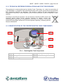
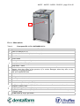
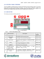
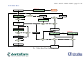
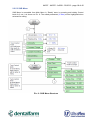
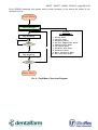
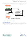
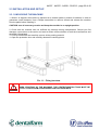
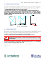
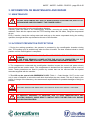
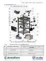
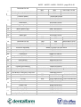
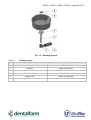
A4507 - A4507I - A4508 - 03/2013 - page 1 of 40
INDUCTION CASTING MACHINE
EC-1 / EC-1 Infrared / EC-2
USER MANUAL
A4507 - A4507I - A4508 - 03/2013 - page 2 of 40
A4507 - A4507I - A4508 - 03/2013 - page 3 of 40
TABLE OF CONTENTS
1.
GETTING STARTED GUIDE............................................................................................ 4
1.1
SAFETY INSTRUCTION ........................................................................................... 4
1.1.1
IMPORTANT NOTES ......................................................................................... 4
1.1.2
SAFETY WARNINGS......................................................................................... 5
1.2
GENERAL INFORMATION ....................................................................................... 7
1.2.1
RECOMMENDED USE ...................................................................................... 7
1.2.2
SUPPLIED ACCESSORIES............................................................................... 7
1.2.3
UNAUTHORISED USE ...................................................................................... 8
1.2.4
PERSONNEL TRAINING ................................................................................... 8
1.2.5
SAFETY DEVICES............................................................................................. 8
1.2.6
NOISE LEVEL .................................................................................................... 8
1.2.7
RESIDUAL DANGER AND EMERGENCY SITUATION..................................... 8
2. INFORMATION ON THE MACHINE OPERATION........................................................... 9
2.1
TECHNICAL DESCRIPTION OF THE MACHINE ..................................................... 9
2.1.1
TECHNICAL DATA ............................................................................................ 9
2.1.2
TECHNICAL REFERENCE REGULATIONS AND TEST PROCEDURES....... 10
2.1.3
IDENTIFICATION OF THE CENTRIFUGATION TANK COMPONENTS ......... 10
2.2
CONTROLS AND OPERATION .............................................................................. 11
2.2.1
FRONT PANEL OVERVIEW ............................................................................ 11
2.2.2
CONTROL PANEL OVERVIEW....................................................................... 13
2.2.3
INDICATORS ................................................................................................... 13
2.2.4
OUTPUT REGULATION AND STATUS MESSAGES...................................... 14
2.2.5
MENUS AND NAVIGATION............................................................................. 15
2.2.6
TUNING AND TROUBLESHOOTING .............................................................. 21
2.3
INSTALLATION AND SET-UP ................................................................................ 23
2.3.1
UNPACKING THE MACHINE .......................................................................... 23
2.3.2
POSITIONING IN THE ROOM ......................................................................... 24
2.3.3
MAIN CONNECTIONS ..................................................................................... 24
2.3.4
INBUILT COOLING CIRCUIT ......................................................................... 25
2.3.5
PRELIMINARY CONTROLS........................................................................... 26
2.4
OPERATING INSTRUCTIONS................................................................................ 27
2.4.1
CRUCIBLES..................................................................................................... 27
2.4.2
MELTING AND CENTRIFUGATION PREPARATION ..................................... 28
2.4.3
CENTRIFUGAL ARM AND CRUCIBLE PREPARATION .............................. 29
2.4.4
MELTING ......................................................................................................... 30
2.4.5
VACUUM MELTING (only for EC-2) .............................................................. 30
2.4.6
INERT GAS INTRODUCTION (only for EC-2 with argon module) ............... 30
2.4.7
CENTRIFUGATION ........................................................................................ 31
3. INFORMATION ON MAINTENANCE AND REPAIR ...................................................... 32
3.1
MAINTENANCE ...................................................................................................... 32
3.2
ACCIDENT PREVENTION PROTECTIONS ........................................................... 32
3.3
SERVICE................................................................................................................. 33
3.3.1
GENERAL ........................................................................................................ 33
3.3.2
SERVICE CONTACT INFORMATION ........................................................... 33
3.4
SPARE PARTS LIST............................................................................................... 34
A4507 - A4507I - A4508 - 03/2013 - page 4 of 40
1. GETTING STARTED GUIDE
1.1 SAFETY INSTRUCTION
1.1.1 IMPORTANT NOTES
o
This operator’s manual is addressed to the owner, for a correct installation, use and
maintenance of the machine.
o
The operator’s manual contains useful information to specify the recommended use of the
machine according to the project hypotheses and technical features, to supply instructions for
the installation, assembly, regulation and use, personnel training, to direct the maintenance
intervention and to supply information on residual risks.
o
It also supplies complete information on all models and all additional modules of the EC series
melting units; you are therefore advised to refer to all the paragraphs concerning the model(s)
in your possession.
o
For a professional use of the machine, this manual can never replace the operator’s specific
experience, however it supplies all the information required for a correct installation and is a
useful reminder of the main basic operations.
o
This manual is an integral part of the machine and should be ‘’kept for future reference’’ until
the final disassembly of the machine. Therefore, its consultation should be allowed near the
machine and it should be kept with due care (protected, in a dry place, away from sun rays or
atmospheric agents, etc.). In case of loss or damage, you can request a new copy from our
dealers, technical service centres or directly from Ultraflex Power Technologies or Dentalfarm.
o
This manual reflects the state-of-the-art at the moment of the machine commercialisation, and
cannot be considered inappropriate only because it has been subsequently amended on the
basis of new experiences.
o
In this document period “.” will be used as a decimal point delimiter.
o
The manufacturer reserves himself the right to amend or update his own production and
relative manuals, without being obliged to update previous productions, unless in exceptional
cases.
o
You can request further details or updates to this manual from our dealers, technical service
centres or directly from Ultraflex Power Technologies and Dentalfarm.
o
Any criticism or suggestion aimed at improving the machine can be sent in writing to our office.
We will be pleased to read them and send our comments to the persons concerned.
A4507 - A4507I - A4508 - 03/2013 - page 5 of 40
1.1.2 SAFETY WARNINGS
To guarantee the utmost operating reliability, Ultraflex Power Technologies and Dentalfarm have
carried out an accurate selection of materials and components to be used in the machine
manufacture. The machine has undergone regular checks before being delivered. The machine’s
productivity over the years also depends on its correct use and an appropriate preventive
maintenance according to the instructions contained in this manual.
All manufacturing elements, connecting components and controls, have been designed and made
with such a safety level that they can resist abnormal strains or strains higher than those specified in
this manual. The materials are of the best quality and their acceptance, storage and use in the
workshop are continuously controlled in order to guarantee the absence of damage, wear and tear,
faulty operation.
In any event, respect the following measures:
- Never use the machine or carry out any intervention on the machine if you have not carefully
read and wholly understood this manual in all its parts. In particular, take all the necessary
measures listed in section 1 - SAFETY INSTRUCTIONS AND INFORMATION.
- It s forbidden to use the machine in conditions or for a use other than that stated in the
manual, and Utraflex Power Technologies and Dentalfarm will not be deemed responsible for
any failure, fault or accident due to the non observance of this prohibition.
This manual is made up of three parts:
SECTION 1: deals with the SAFETY INSTRUCTIONS AND INFORMATION
SECTION 2: illustrates the MACHINE CHARACTERISTICS - OPERATION - TRANSPORT AUXILIARY EQUIPMENT ASSEMBLY – EQUIPMENT SHUTDOWN - CIRCUIT DIAGRAMS.
SECTION 3: deals with the MAINTENANCE INTERVENTIONS, LUBRICATION and includes the
SPARE PARTS LIST AND DESCRIPTION.
NOTE: IT IS FORBIDDEN TO TAMPER WITH, ALTER OR CHANGE, EVEN PARTIALLY, THE
MACHINE OR EQUIPMENT REFERRED TO IN THIS OPERATOR’S MANUAL, AND IN
PARTICULAR THE GUARDS FITTED FOR THE PERSONS’ SAFETY.
IT IS ALSO FORBIDDEN TO OPERATE IN A WAY OTHER THAN THE SPECIFIED WAY, OR TO
NEGLECT SAFETY RELATED OPERATIONS.
Operations, for which the non-observance of the instructions can lead to damages to the
machine or other parts related to the machine or to the surrounding environment, will be
indicated in the manual by this sign
Operations for which the non-observance of the instructions or the tampering with the
equipment parts can lead to injuries to people, will be indicated in the manual by this sign
A4507 - A4507I - A4508 - 03/2013 - page 6 of 40
During the machine operation, the operator is protected by the centrifugation chamber closed door.
The working cycle is only possible after the door has been closed and locked. The protection remains
locked in closed position until the cycle is over.
DURING THE WORKING CYCLE, THE PROTECTION DOOR SHOULD NOT BE
FORCED OPEN. IF, AT THE END OF THE CYCLE, THE DOOR REMAINS LOCKED,
DO NOT FORCE THE OPENING AND CONTACT OUR SERVICE DEPARTMENT.
The compartment underneath the centrifugation chamber houses the control and power electric
circuits and the arm rotation motor. This compartment is isolated from the operator by fixed bulkheads.
The bulkheads are kept in position with screws that can only be removed with special wrenches
supplied with the machine.
EMERGENCY COVER OPENING: In case of a black out, to unlock the cover, remove the left side
panel, and using the unlock tool 56.67, supplied in the accessories kit, push the locking pin back to
release the cover free.
THIS KEY SHOULD BE USED ONLY IN CASE OF POWER SUPPLY FAILURE,
DURING THE CASTING OPERATION.
1.1.3 GROUNDING
This product is a Class 1 device which utilizes protective grounding to earth to ensure operator‘s
safety.
PROTECTIVE EARTHING CONDUCTOR TERMINAL -This symbol indicates the point
on the product to which the protective grounding conductor must be attached.
EARTH (GROUND) TERMINAL -This symbol is used to indicate a point which is
connected to the PROTECTIVE EARTHING TERMINAL. The component
installer/assembler must ensure that this point is connected to the PROTECTIVE
EARTHING TERMINAL.
CHASSIS TERMINAL -This symbol indicates frame (chassis) connection, which is
supplied as a point of convenience for performance purposes. This is not to be confused
with the protective grounding point, and may not be used in place of it.
A4507 - A4507I - A4508 - 03/2013 - page 7 of 40
1.2 GENERAL INFORMATION
1.2.1 RECOMMENDED USE
EC-1, EC-1 Infrared and EC-2 are a centrifugal melting unit with medium frequency inductive heating,
designed to melt all types of metals. The safety devices fitted on the machine make it safe and
reliable in time.
1.2.2 SUPPLIED ACCESSORIES
Table 1:
Accessories EC-1, EC-1 INFRARED, EC-2
1 pair of tongs for cylinder and crucible,
Part Number: 4HVM-000-101-00 (Code 03.55.120.0001)
1 cylinder spacer 25mm,
Part Number: 2MAS-015-200-AN (Code 06.00.170.0035)
4 cylinders saddles in various sizes
•
30 mm, Part Number: 2DET-015-200-LT (Code 06.00.110.0049)
•
48 mm, Part Number: 2DET-015-200-LN (Code 06.00.110.0048)
•
65 mm, Part Number: 2DET-015-200-LU (Code 06.00.110.0047)
•
80 mm, Part Number: 2DET-015-200-LS (Code 06.00.110.0046)
1 refractory crucible,
Part Number: 2DET-015-000-KB (Code 03.40.180.0008)
1 graphite crucible,
Part Number: 2DET-015-000-KC (Code 03.40.180.0006)
4 feet for the centrifuge, (already installed)
Part Number: 4AEC-000-023-00 (Code 03.40.060.0001)
1 blue protection lens, (already installed)
Part Number: 6VMT-000-007-00 (Code 01.10.998.0001)
1 screwdriver for protection panels,
Part Number: 4HVM-000-100-00 (Code 03.55.100.0001)
1 unlock tool (Code 56.67)
A4507 - A4507I - A4508 - 03/2013 - page 8 of 40
1.2.3 UNAUTHORISED USE
The EC-1, EC-1 Infrared and EC-2 melting unit has NOT been designed for melting alloys that are not
used for odontotechnic purpose.
The crucibles from materials others than ceramics or graphite have not to used.
The metal cannot undergo centrifugation melting if the doors are opened.
1.2.4 PERSONNEL TRAINING
The EC-1, EC-1 Infrared and EC-2 melting unit has been designed and built to be used by personnel
qualified in odontotechnics; these persons are supposed to be perfect acquainted with the work
execution procedures and with the characteristics of the materials to be used.
An accurate reading of this manual and a short training under the supervision of qualified personnel is
recommended.
1.2.5 SAFETY DEVICES
The machine is supplied complete with the devices required to guarantee the operator’s safety:
1. Door locking during rotation.
2. No melting start if water is missing.
3. No melting start if the water temperature is too high.
4. No melting start if the coil does not rise.
5. No coil rises if the pressure is missing.
6. No coil rises if the position is not aligned with the crucible.
7. Red mushroom emergency stop on yellow background. It should be used:
7.1. To avoid, as soon as they arise, dangers to people;
7.2. To reduce, when they arise, damages to the machine or the on-going operation. USE
MODERATELY.
1.2.6 NOISE LEVEL
The measure has been taken with the machine in the centrifugation phase, as this is the operation
with the highest noise emission.
1. Phonometric measurement in compliance with UNI 9432.
2. Noise meter: Bruel & Kjaer 2218, with wad filter 1613 № 895445.
3. Weighting filter: Curve A.
4. Measuring system: Тhe exposures are calculated starting from noise pressure measures and
integrating for the time of exposure.
5. Estimated equivalent continuous noise level A in the working station is L Aeq1Tp = 68.7
1.2.7 RESIDUAL DANGER AND EMERGENCY SITUATION
1. Avoid direct contacts with the melting coil during the heating phase (ELECTRIC
HAZARD).
2. Avoid introducing metal objects inside the melting coil without the appropriate
crucible (ELECTRIC AND THERMAL HAZARD).
3. Avoid direct contacts with the mechanical parts situated near the crucible; use
supplied prongs and wear suitable gloves to manipulate crucibles and cylinders
(THERMAL HAZARD).
4. Avoid any type of intervention on the machine before the machine has been
disconnected from the electric supply.
Note: The above residual dangers are indicated on the machine by specific labels.
A4507 - A4507I - A4508 - 03/2013 - page 9 of 40
2. INFORMATION ON THE MACHINE OPERATION
2.1 TECHNICAL DESCRIPTION OF THE MACHINE
The EC-1 melting unit consists of a steel framework supporting the centrifugation tank, and a steel
plate panelling closing the machine. On top of the machine, a door opens in a compasses movement
to give access to the working compartment. This door is fitted with a safety lock.
The melting circuit, based on the current oscillation principle (105 kHz) in such a way as to create an
alternate magnetic field, uses the new generation IGBT Transistors technology , which guarantees a
better yield of the power circuit, lower consumption and excellent reliability in time.
This type of circuit offers two essential advantages:
Low current consumption.
The metal melting takes place from the inside toward the outside; this allows a more accurate reading
and the risk of burning the metal is highly reduced.
Due to the magnetic field, the metal undergoes a continuous mixing, which returns all the alloy
components to their position in the initial state ; in the melting point, the metal starts ‘’rising’’ and
comes off the crucible, thus giving clear evidence of the melting.
Lastly, the machine is fitted with some automatic devices, for an easier work, such as:
Centrifugation time out preset on 40 seconds.
Pneumatic coil rise.
2.1.1 TECHNICAL DATA
Table 2:
Technical Data EC-1, EC-1 Infrared and EC-2
SPECIFICATION
DESCRIPTION
EC-1
Frequency
Weight
EC-1 Infrared
EC-2
95÷110 kHz
100 kg
100 kg
110 kg
Width
485 mm
Depth (at base and max)
550 mm / 606 mm
Height
1055 mm
Electric power supply
230±10% Vac single phase - 50/60 Hz
Maximum absorbed power
3.0 kW
Air pressure for coil movement
Min. 4 bar – Max. 8 bar
Argon pressure
1.0 bar
Operating temperature
0°C - + 40°C
Crucible maximum capacity
Au = 80 g - Cr/Co = 60 g
Minimum melting capacity
Au = 10 g - Cr/Co = 10 g
Admitted flask diameter
Min. 20 mm - Max. 100 mm
whit the suitable flask available upon request
Flask length
Min. 50 mm – Max. 100 mm
whit the suitable spacer available upon request
A4507 - A4507I - A4508 - 03/2013 - page 10 of 40
2.1.2. TECHNICAL REFERENCE REGULATIONS AND TEST PROCEDURES
This equipment is mass-manifactured by Ultraflex Power Technology, Inc. under the supervision of
C.I.E. Dentalfarm, in compliance with technical and safety rules in force, as provided for by the 89/392
EEC Community Directive on machinery. The product is labeled CE and accompanied by a
Declaration of Conformity. Careful inspection and full routine testing are carried out singularly on each
machine.
According to International regulations, this unit has been classified as AEE (electric and
electronic device, whose correct operation depends on electric currents and
electromagnetic fields) and as a consequence, at the end of its lifetime, it can not be
treated as normal waste material but it must be disposed separately, complying with the
Directive 2002/96/CE.
2.1.3 IDENTIFICATION OF THE CENTRIFUGATION TANK COMPONENTS
1.2
1.1
1.4
1.3
1.5
Pic. 1 - Centrifugation Tank Components
1.1
Counterweight
1.4
Supporting saddle (4 types)
1.2
Viewing window
1.5
Crucible lid locking lever
1.3
Crucible support
A4507 - A4507I - A4508 - 03/2013 - page 11 of 40
2.2 CONTROLS AND OPERATION
2.2.1 FRONT PANEL OVERVIEW
The above drawing represents the control section of EC-1, EC-1 Infrared and EC-2. Therefore, if the
model you have bought is not complete will all the modules, some sections will be missing on your
instrument panel.
10
2
3
4
8
7
13
12
9
5
6
Pic. 2 - Front Panel EC-1, EC-1 Infrared
13
Pic. 3 - Front Panel EC-2
12
11
A4507 - A4507I - A4508 - 03/2013 - page 12 of 40
1
Pic. 4 – Main switch
Table 3:
Front panel EC-1, EC-1 INFRARED, EC-2
№
Description
1
Power On Switch (Pic. 4)
2
Green Lamp – Power On Light (electric supply)
3
Alarm Buzzer
4
Control Panel
Power generator stop, centrifugation, and coil down button
5
Lamp lights – Mode “Ready”
6
7
Lamp blinks – Alarm
Red mushroom emergency push-button, on yellow background. To be used: 1) to avoid
dangers, when they arise, to the persons; 2) to reduce damages, when they arise, to the
machine or on-going operations.
USE WITH MODERATION
Induction coil rise and down button
8
Melting start button
9
Centrifugal start (Injection) button
10
Control Knob
11
Vacuum meter (Pic.3 - only for EC-2)
for EC-1 and EC-1 Infrared (Pic.2): “Menu” button button - Shortcut to the Setup Menu when
pressed in “Ready” state
for EC-2 (Pic.3): Vacuum and Devacuum button
for EC-1 and EC-1 Infrared (Pic.2): “Service” button - Shortcut to Service Menu when pressed
in “Ready” state
for EC-2 (Pic.3): Argon gas button
12
13
A4507 - A4507I - A4508 - 03/2013 - page 13 of 40
2.2.2 CONTROL PANEL OVERVIEW
The unit is digitally controlled through a control panel located on the front panel of device. The control
panel utilizes the latest microprocessor technology. The control panel is designed to display vital
parameters and alpha-numeric messages providing intuitive and informative visual feedback. The
users can also navigate through easy to use service, diagnostics and setup menus.
2.2.3 INDICATORS
The Control panel has the following indicators:
1
2
3
4
5
6
7
Pic. 5 - Control panel
Table 4:
№
Control and indicators Table
Name/Function
1
Output Power
2
Temperature
reading
3
Output Power
4
Speed
5
6
7
Temp: LED
[AMBER]
Segment LED
indicators showing
Output Power,
Speed or Temp
Alphanumeric LCD
display
Description
BAR-GRAPH: The reading corresponds to the
percentage of the measured power.
BAR-GRAPH: The reading corresponds to the
percentage of the measured temperature.
The set point of Output Power: LED [AMBER] Illuminated when display(6) is showing the output
power
Time: LED [AMBER]- Illuminated when display(6)
is showing centrifugal speed, [RPM]
Temp: LED [AMBER]- Illuminated when display(6)
is showing current temperature
Four red 7 segment LED indicators showing
Output Power, Centrifugal Speed
or Temp
depends on items 3, 4 and 5
Alphanumeric LCD display (20 characters / 2 rows)
for displaying measured parameters, status
messages, fault messages and menu screens.
Indicator
/
Control
INDICATOR
INDICATOR
INDICATOR
INDICATOR
INDICATOR
INDICATOR
INDICATOR
A4507 - A4507I - A4508 - 03/2013 - page 14 of 40
2.2.4 OUTPUT REGULATION AND STATUS MESSAGES
The following diagram describes a typical LCD display screen with message types and locations
on the screen.
1. Possible Messages
on Ready position:
READY
COIL UP
INJECT
MELT
READY
1080
TEMPERATURE
2. - - - - Temperature
Set point
100 %
Vacuum
380rpm
POWER
SPEED
3. Heating Power
Set point
5. - - - - Vacuum
Argon
Vent.
4. Speed
Set point
Pic. 6 - LCD display functions
Table 5:
Control Modes and Messages Table
Name/Function
Description
Indicator/
Control
1
Status Messages
Shows the current status of the system when in operational
mode:
READY – When there are no faults and the power supply is
ready to be turned on;
COIL UP – After pushing button COIL. If there are no faults,
coil goes up;
MELT – After pushing button MELT. If there are no faults,
inverter starts;
INJECT – After pushing button INJECT. If there are no
faults, coil goes down and centrifugal motor starts.
INDICATOR
2
for EC-1: - - - - for EC-1 Infr., EC-2:
Temperature
set point
3
Current Output
Power
№
4
Speed
Temperature. The set point of temperature regulator can be
adjusted by rotating the Control Knob while the Amber
“Temp °C” LED is illuminated.
Temp range – The Temp value can be adjusted from 750°
to 2000° in steps of 1°C.
The Output power can be adjusted by rotating the Control
Knob while the Amber “Output, %” LED is illuminated.
Power range – The Power value can be adjusted from 10%
to 100% in steps of 1%.
The Centrifugal Speed can be adjusted by rotating the
Control Knob while the Amber “Speed rpm” LED is
illuminated. Speed range – The Speed value can be
adjusted from 10 to 500 trn/min in steps of 1 trn.
INDICATOR
INDICATOR
INDICATOR
A4507 - A4507I - A4508 - 03/2013 - page 15 of 40
5
Vacuum and Gas Argon Control:
for EC-1, EC-1 Iinfrared: Gas Argon and Vacuum Control
for EC-1, EC-1 Infr. are not provided.
for EC-2: VACUUM – After pushing button VACUUM,
-----vacuum pump starts;
DEVACUUM – After pushing and hold for 1.5 min. button
for EC-2:
VACUUM, the pressure in the chamber was recovering;
Regulating flow
ARGON – After pushing button ARGON, the chamber
Vacuum,
Devacuum or
Gas Argon
INDICATOR
starts to be filled with argon gas;
TIME OUT VACUUM – Time Out for Vacuum is 1.0 min.;
TIME OUT DEVACUUM – Time Out for Devacuum is 10 sec.
TIME OUT ARGON – Time Out for gas Argon is 40 sec.
2.2.5 MENUS AND NAVIGATION
2.2.5.1 General Navigation Rules
Rotate Control Knob Clockwise or Counterclockwise to scroll through the menus, change values or
toggles between 2 Melt Screens. Press Control Knob to select menu or accept the changes.
When scrolling through service menus:
- Pushing the Control Knob selects the parameter;
- Selecting the Exit option will return to the previous menu;
- Start and Stop buttons are disabled when in Service menus.
A4507 - A4507I - A4508 - 03/2013 - page 17 of 40
2.2.5.2 Main Menu
Initial screen
Easy Cast
EC 1-T/200
REV. 1.0
2 sec. delay
POWER ON
Main Menu
N
READY
1080
Ready Screen
----100 % 450rpm
“COIL”
Button?
Y
Coil DOWN
Coil UP
“COIL”
Button?
N
N
“INJECT”
Button?
COIL UP
1080
100 %
----450 rpm
N
Y
Coil Down
Lid Lock
Start Spin Motor
“INJECT”
Button?
Y
“MELT”
Button?
N
Y
N
INJECT
1080
100 %
Y
Inject Screen
----450rpm
Start Inverter
N
“STOP”
Button?
N
“INJECT”
Time out?
Melt Screen2
Melt Screen1
Stop Inverter
MELT
1080
100 %
----450rpm
Y
Stop Spin Motor
Start 4 sec. delay
Y
12A
1080
225Vdc
120 kHz
Y
N
Delay
Off?
Press
Control
Knob
to Toggle
Y
“INJECT”
Button?
N
“MELT”
Time out?
“STOP”
Button?
N
Y
Unlock Lid
Stop Inverter
Coil Down
Pic. 7 - Main Menu Flow Chart Diagram
Y
2,7kW
100 %
A4507 - A4507I - A4508 - 03/2013 - page 18 of 40
2.2.5.3 SUB Menu
SUB Menu is accessible from Main Menu in “Ready” state, by pressing and holding Control
knob for 2 sec. It is shown on Pic. 8. The edited parameters (in blue) will be highlighted when
selected for editing.
Pic. 8 - SUB Menu Structure
A4507 - A4507I - A4508 - 03/2013 - page 19 of 40
2.2.5.4 SUB Menu Options
1.
2.
3.
4.
5.
6.
Acceleration – defines the acceleration time of the motor from 0 to the preset speed.
Rotating Time – set rotating time for centrifuge in seconds.
Emissivity – emissivity coefficient for certain alloy.
Firmware Change – Service menu for updating the software control panel.
Coolant Flow Menu – set point and current indication of water Flow menu.
Service Menu:
6.1 Counter – accumulation of casting cycles;
6.2 Auto Tune – automatically lock the resonant frequency of tank circuit;
6.3 Temperature Menu:
6.3.1 Temperature Control – switching on and off temperature regulator, all other
parameters are valid the regulator is switched On and are not valid when it is Off;
6.3.2 Min Power – minimum permissible power that can be fed to the output;
The parameters 6.3.3, 6.3.4 and 6.3.5 are parameters of PID Control law;
6.3.3 Temp Zone – Zone for proportional part of PID control law of the regulating;
6.3.4 Integral Gain – integral gain of PID control law;
6.3.5 Derivat Gain – derivat gain of PID control law;
6.3.6 EXIT – returning to SUB Menu.
6.4 Factory Menu– Only for factory staff.
6.5 EXIT – Returning to Coolant Flow Menu.
7. EXIT – Exit – Returning to Main Menu.
A4507 - A4507I - A4508 - 03/2013 - page 20 of 40
Every ERROR messages that appear during normal operation of the device are shown in the
flowchart in Pic 9.
Fault Menu
ALARM
“Fault Message”
List of
Fault Messages
Start “STOP” Button
Lamp Blinking
N
“STOP”
Button?
Y
Y
End “STOP” Button
Lamp Blinking
1.Tuning Fault
2.Current Fault
3.Frequency Fault
4.PS Over Temperature Fault
5.Communication Fault
6.Int.Board Fault
7.PS Water Flow Fault
8.Interlock Fault
9.Motor Contactor Fault
10.Coil Position Fault
Fault
Condition?
N
Main Menu
Pic. 9 - Fault Menu Flow chart Diagram
A4507 - A4507I - A4508 - 03/2013 - page 21 of 40
Every WARNING messages that appear during normal operation of the device are shown in the
flowchart in Pic.10.
Warning Menu
Warning !
“Warning Message”
List of
Warning Messages
2 sec. delay
N
Delay
OFF?
Y
1.Wrong Arm Position
2.Top Lid opened
3.End Time Out Heating
4.End Time Out Inject
5.Low Air Pressure
6.Coil is Down
Main Menu
Pic. 10 - Warning Menu Flow chart Diagram
2.2.6 TUNING AND TROUBLESHOOTING
2.2.6.1 LOAD TUNING GUIDE
Because of fixed tank circuit and load device is factory tuned and does not need additional load
tuning.
A4507 - A4507I - A4508 - 03/2013 - page 22 of 40
2.2.6.2 ALARMS, FAULTS AND WARNINGS
Table 6:
Alarms, Warnings (W) and Fault (F) Messages
Fault
W
Condition
Cause
Description
F
You tried to move up the
Wrong Arm
Arm is not in zero
W
coil, while the arm was
Position
position
not positioned correctly
Top Lid
You tried to cast with
W Top Lid Opened
Opened
open cover
Melting has
End Time
Expired time out for melt
W reached 3
Out heating
before manual stop
minutes
Casting has
Expired time out for
End Time
W reached 40
casting before manual
Inject
seconds
stop
You tried to move the coil
Low Air
There pressure is
without enough air
W
pressure
below for 4 bars
pressure
You tried to melt
If you press MELT button
Coil Is Down W
with coil down
when the coil is down
Tuning Fault
F
Primary V & I out
of phase
Can't find resonant
frequency
Current Fault
F
I primary > I Max
Output current exceeds
the limit
Frequency
Fault
F
F < Fmin or F >
Fmax
Frequency goes out of the
pre-programmed range
during Heat On
PS Over
Temperature
F
T°heat sink >45°C
The heat sink of the
power supply exceeds the
max allowed T°
Communi
cation
Fault
F
Int. Board
Fault
F
PS Water
Flow Fault
Interlock
Fault
Motor
Contactor
(KM2) Fault
Coil Position
Fault
Communication
Error Between
Panel and Control
Board
No connection
with Interface
board
Advice
Adjust the arm in zero
position
Close the lit and try again
----Increase input air pressure
Move up the coil
Check resonant loop
connections - load coil, tank
capacitors. transformer taps
Possible FET/IGBT failure in
the Power supply. Contact
our Service department
Check resonant loop values,
tank capacitors or control
board. Check load coil for
shorted turns.
Check fans, blockages of
the vents or fan filters,
cooling water temperature
or water filters.
No acknowledgment is
received after the last
command
Check cables and RS
connectors between boards
No acknowledgment is
received after the last
command
Check cables and RS
connectors between boards
F
Water Flow < 2
l/min (0.5GPM)
Restricted or no water flow
F
The lock on the
lid is not working
Interlock does not execute
commands
Check cooling water flow
rate and water pressure.
Check hoses and external
water filter for blockages.
Check flow switch.
Check Interlock and Interlock
sensor
F
Motor Contactor
is welded
Contactor damage
Change contactor
F
Coil is not
moving as
expected
When the coil does not
execute commands
Contact our Service
department
A4507 - A4507I - A4508 - 03/2013 - page 23 of 40
2.3 INSTALLATION AND SET-UP
2.3.1 UNPACKING THE MACHINE
1. When it is shipped, the machine is fastened on a wooden pallet by means of brackets, in order to
guarantee a safe transport. Use a Phillips screwdriver to remove screws and release the machine
from the pallet before installing it.
CAUTION: use all necessary caution and keep the machine in an upright position.
2. Check that the machine has not suffered any damage during transportation. Should you find
damages, report them to the carrier and send a written communication to both the manufacturer and
the dealer immediately.
3. Pick up accessories and carefully remove all the packing material
4. Open the protection door and carefully release the centrifugal arm.
Pic. 11 – Fixing brackets
WHEN STARTING UP THE MACHINE, THE CENTRIFUGATION TANK MUST BE
TOTALLY FREE FROM ACCESSORIES AND PACKING MATE.
A4507 - A4507I - A4508 - 03/2013 - page 24 of 40
2.3.2 POSITIONING IN THE ROOM
The machine must be installed in a properly ventilated room for a correct scavenging of fumes and
steams that build up during the melting process. In order to reduce possible risks in handling hot
materials, it is recommended to install the machine near the heating furnace and the service sink.
1. PLACE THE MACHINE ON A PERFECTLY FLAT SURFACE.
2. When the machine is installed, check THAT IT IS PERFECTLY STABLE AND HORIZONTAL.
A total stability is absolutely essential during the centrifugation arm rotation. If necessary, adjust the
machine position with the feet supplied with the machine, to adapt it to the floor. DO NOT INSERT
ANY SHIM BETWEEN THE FEET AND THE FLOOR. With a level gauge, check that the upper
surface is perfectly flat.
Pic. 12 – Perfect stability
2.3.3 MAIN CONNECTIONS
Make sure the power supply voltage is the same as the voltage indicated on the identification plate on
the machine rear panel. Check that the available power is sufficient (see table: Technical data).
1. USE AN AC MAINS OUTLET, type 25 A, 250 VAC, SINGLE PHASE
Using an AC current supply other than the specified supply may damage the machine.
Remember the machine must be grounded. Check the efficiency of your electric
supply installation.
2. Connect the compressed air circuit with the appropriate connection (see Pic. 11). For a proper
operation, the pressure should be between 4 and 8 bars.
Should it be lower red light blinks (Pic.2 - 5) and the LCD-display (Pic.4 - 7) shows an error:
Air pressure fault.
A4507 - A4507I - A4508 - 03/2013 - page 25 of 40
2.3.4 INBUILT COOLING CIRCUIT
The cooling system is built in. A pressure gauge controls the water flow and locks the machine
operation in case of low pressure.
To fill in the cooling circuit, proceed as follows:
1. Unscrew the cap of the round fitting, marked with “Water In”, located on the rear panel of the
machine. - Cap fitting 1/2”.
2. Open the “overflow” fitting – Pic. 10-2.1 bellow. Put a water vessel under this fitting – if you fill the
tank too much water will start overflowing from there.
This outlet must always be open when you fill in the water tank and closed after that!
3. Start pouring water inside the tank using a funnel.
4. Fill in the tank with approximately 18 liters of demineralised water until overflow-overflow fitting.
5. Monitor water gauge, located at the bottom of the rear panel!
6. Check the water level every 12 months.
3. Funnel
Level
gauge
1. Cap Fitting ½”
2.1 Cap Fitting overflow
2.2 Water vessel
Pic. 13 – Rear Panel
ATTENTION!
DO NOT FILL THE WATER TANK WITH WATER PRESSURE!
A completely full tank allows carrying out 16 consecutive melting
operations. If the laboratory needs to carry out more melting operations,
replace the water in the tank or fit the machine with an external tank.
To empty the cooling circuit, proceed as follows:
1. Connect the L fitting, situated at the rear of the melting machine, marked with”WATER OUTLET”
with a suitable pipe.
2. Open the tap and insert other end of the pipe into sewage or a container of about 20 litters.
3. Start the machine with the main switch ON (Pic.2-1); the machine starts draining water.
A4507 - A4507I - A4508 - 03/2013 - page 26 of 40
2.3.5 PRELIMINARY CONTROLS
1. Check that the air circuit have been connected (there must be no leaks, bleeds, etc.) and the
power supply is on.
2. Check that the centrifugation chamber is free from any accessory.
3. Check that the emergency push-button (Pic.2-6) is disconnected; to unlock the emergency, rotate
the push-button in the direction of the arrow.
4. IN CASE OF FAILURE - If a malfunction is observed during the operation, or if the indicators give
wrong information, immediately disconnect the machine and contact the dealer or an authorised
service centre.
5. EMERGENCY STOP CONTROL - This mushroom type push-button is red on yellow background.
It should be used:
o to avoid, danger to operator;
o to reduce, damages to the machine or to on-going operations.
USE WITH MODERATION!
A4507 - A4507I - A4508 - 03/2013 - page 27 of 40
2.4 OPERATING INSTRUCTIONS
2.4.1 CRUCIBLES
We strongly recommend following strictly the following useful hints in order to obtain the best
results from your casting machine.
Ceramic crucibles: RT101, RT100 and RT104 (packs of 6 pcs.).
RT101: Standard crucible, standard mixture, recommended for casting non-precious and CrCo alloys.
RT100: Ceramic crucible with lining in silicon nitride providing considerably longer life of the
crucible. Especially recommened for non-precious alloys for ceramic. Top performance is
nevertheless assured when using any other non-precious alloy.
RT104: Ceramic crucible with lining in zirconia, assuring highest flowing of metal. Particularly
recommended for palladium alloys.
Note: The first two above illustrated crucibles have to be pre-heated for at least 5-10 minutes
before use, usually in the same furnace where the casting rings are heated; do not forget to
remove the slags left inside the crucible. No vitrification required.
Crucibles with graphite lining.
RT102: Plumbago crucible, suitable to cast all those precious alloys which can not be
contaminated by this material – NO PALLADIUM (pack of 6 pcs.).
RT103: (single pack) Crucible in sintered graphite suitable to cast both the palladium alloys
and any precious alloys. The casting result of precious alloys is particularly improved. During
the first use, take care to heat slowly the crucible: set the casting power rating at the lowest
value (press key 10 of ill. 2 until only one the multifunction led indicators keeps lit (A, ill. 2))
during the metal heating process so that too much difference in temperature never occurs
between the heated metal and the crucible.
Note: The introduction of pieces which, due to their shape and/or dimension get stuck
between the crucible walls, may cause the crucible to break.
During the heating process, these pieces will expand and exert a strong pressure on the
crucible walls thus causing them to crack.
A4507 - A4507I - A4508 - 03/2013 - page 28 of 40
2.4.2 MELTING AND CENTRIFUGATION PREPARATION
Before attempting to melt any type of alloy, refer to the technical data and processing data relative to
the metals used, supplied by the alloys manufacturers.
Choose the type of crucible to be used according to the alloys chemical characteristics (see attached
table for details).
Note: Always refer to the indications supplied by the alloy manufacturer.
Use a crucible in good working conditions. If necessary, replace the crucible with a
new one to prevent it from breaking, which could damage the melting unit or
produce bad melting.
1. Introduce the metal to be melted into the crucible;
2. Check that the metal reaches the bottom of the crucible and does not remain stuck at the top of the
crucible;
3. Reuse of old alloy: Check with the alloy manufacturer if previously melted metal (in vacuum, argon
or atmosphere) can be reused and if a percentage of new metal should be added. If this is possible, it
is advised to eliminate all oxide traces (for example through sandblasting), and to cut it in appropriate
portions to introduce it inside the crucible in such a way as to achieve the maximum contact between
the various metal parts;
4. Prepare the cylinder following the instructions supplied by the coating supplier, depending on the
technique used, i.e. free expansion or steel cylinder;
Choose the cylinder dimensions according to the free expansion technique or the
steel cylinder. The dimensions must be suitable for the work to be carried out and to
the melting unit cylinder saddles. Place the cylinder saddle on the corresponding
supports on the centrifugal arm, choosing the most appropriate size for the cylinder
dimensions.
5. Introduce the crucible into crucible support (1.3) and direct it toward the cylinder conical raiser.
6. Use the spacer supplied with the machine if the distance between the crucible support and the
cylinder is over 10 mm.
1.2
1.3
Pic. 14 – Balancing
7. Balance the weights: Unscrew the outer cylinder. Then, adjust the position of the counterweight,
formed by the two knurled cylinders, to find the balance point. Turn again tight against the outer
cylinder internal. The arm balancing has some tolerance; this allows storing the counterweight
position on the numbered arm for each type of cylinder, notwithstanding the metal quantity.
A4507 - A4507I - A4508 - 03/2013 - page 29 of 40
The more accurate the set-up is, the lower are the machine vibrations.
The table below shows to operator the acceleration adjustment according to the metal used:
Adjustment acceleration according to the metal used.
METAL
Gold alloys
Palladium alloys, steel
ACCELERATION
50%…75% of the maximum value
75% …90% of the maximum value
NOTE: Acceleration should be adjusted according to the weight and type of the material to
be centrifuged (specific weight). In general, low accelerations for heavy weights and higher
accelerations for lighter weights.
8. Remove the cylinder before preheating.
2.4.3 CENTRIFUGAL ARM AND CRUCIBLE PREPARATION
DURING THE MELTING OPERATION, HIGH TEMPERATURES ARE REACHED IN THE
CRUCIBLE. HANDLE WITH CARE AND USE APPROPRIATE GLOVES AND TONGS.
1. Switch on the machine (and prepare it for work) turning the main switch (Pic. 2 - 1) to the up.
The green light “ON” (Pic.2 - 2) must light up.
2. Position the centrifuge arm by aligning the crucible axis with that of the heating coil.
3. Press the coil lifting push-button (Pic.2-7). As it rises, it will wind around the crucible. When the
correct height is reached, the coil button lamp will turn on and the coil will lock in position for the
melting operation.
If the arm position is not correct, the coil does not rise.
if the correct height is not reached for the melting, you must verify the air pressure
and check for any objects inside the chamber, that may block the rising
movement of the heating coil.
4.
5.
6.
7.
Position the crucible holding plate (Pic.1-1.3) to the rotation centre (above the coil).
Introduce the material to be melted into the crucible.
Introduce the crucible into its housing (Pic.1-1.3).
Lock the crucible with the lever (Pic.1-1.5) on the crucible side.
A4507 - A4507I - A4508 - 03/2013 - page 30 of 40
2.4.4 MELTING
1. Lower the cover.
During the melting process, a light gas formation is released from the metal mass.
This can be dangerous only when the operator performs the melting process,
willingly and consciously, with the lid open and directly breathes above the crucible.
2. Press the power push-button (Pic.2 - 8). The yellow light “ON” turns on and, after 4 or 5 seconds,
the LED bar (Pic.2 - 4) shows the absorption; the absorption should be set according to the type and
quantity of metal, by rotating the control knob (2.10) to the right to increase the melting power (and
thus the melting speed).
3. While the metal is heating up, open the protection door and load the flask (which has been heated
separately according to the procedures supplied by the manufacturer).
For a direct vision of the melting process, use the anti-UV screen on the lid opening
or use appropriate safety glasses.
Once the metal is melt, the centrifugation process can be carried out (refer to section
“CENTRIFUGATION”).
2.4.5 VACUUM MELTING (only for EC-2)
In vacuum melting, it is recommended to preheat the cylinder in the furnace, at the
required temperature, for a longer period of time with respect to the traditional
melting systems.
1. Prepare the crucible in its support (Pic.1-1.3) with the metal to be melted. Introduce the preheated
cylinder and close the protection cover.
2. Press the push-button (Pic.3-3.12) to start the air suction process from the centrifugation chamber.
Once a negative pressure of – 0.8 bars is reached (see vacuummeter Pic.3-3.11), the pump can be
switched off by pressing again the push-button (Pic.3-3.12).
2.4.6 INERT GAS INTRODUCTION (only for EC-2 with argon module)
Check that the gas bottle is connected, the valve is open and it is fitted with the
appropriate pressure regulator.
When the protection cover is closed, press the push-button (Pic.3-3.12) so that the air in the
centrifugation chamber is sucked. As soon as the vacuum meter shows a negative pressure of - 0.8
bars (Pic.3-3.11), the pump can be switched off. Press the push-button (Pic.3-3.13) to start the gas
introduction process, checking the pressure inside the centrifugation chamber. When the vacuum
meter (Pic.3-3.11) shows a pressure close to -0,2, interrupt the gas introduction and press the pushbutton (Pic.2-8) to start the metal heating process.
A4507 - A4507I - A4508 - 03/2013 - page 31 of 40
2.4.7 CENTRIFUGATION
1. Make sure that the flask is perfectly positioned. Close protection door and wait until the metal is
completely melted.
2. Press push-button (Pic.2-9) to start the centrifugation process.
3. When the centrifugation is completed automatically, or if it is stopped with the push-button STOP
(Pic.2-5), wait until the safety locking system unlocks the lid. Open the lid and remove the flask with
the appropriate tongs.
For all materials, the centrifuge keeps the preset speed for about 40 seconds then it
stops. The door remains locked for 5 seconds after the centrifugal motor has been
stopped.
A4507 - A4507I - A4508 - 03/2013 - page 32 of 40
3. INFORMATION ON MAINTENANCE AND REPAIR
3.1 MAINTENANCE
BEFORE PERFORMING ANY KIND OF MAINTENANCE INTERVENTION, SWITCH OFF
THE MACHINE AND DISCONNECT THE POWER SUPPLY.
Remove all accessories from the centrifugation chamber.
Carefully clean the inside of the centrifugation chamber, removing all coating fragments or metal
residues. Clean with the upmost care the PTFE bushing where the coil slides, using the compressed
air gun.
Every 6 months, check the cooling water tank and top up the water evaporated during the melting
operation, through the filler cap situated at the rear of the machine.
3.2 ACCIDENT PREVENTION PROTECTIONS
1. During the melting operations, the operator is protected by the centrifugation chamber closing
door. The working cycle is enabled only when the door is lacked. The door remains locked in closed
position until the centrifugation is completed.
DURING THE WORKING CYCLE, DO NOT FORCE THE PROTECTION DOOR
OPENING.
IF THE DOOR REMAINS LOCKED AFTER THE CYCLE IS COMPLETED, DO NOT
FORCE IT OPEN AND CONTACT THE AUTHORISED ASSISTANCE SERVICE.
2. The compartment underneath the centrifugation chamber houses the control and power electric
circuits and the arm rotation motor. This compartment is isolated from the operator by side covers of
frame. These protections are fitted in position by screws that can be removed with the special
wrenches supplied with the machine.
3. The LID can be opened with EMERGENCY KEY (Table 1 - Code Number: 56.67): to be used
only in case of blackout to unlock the safe latch that keeps the door closed. This key is kept by the
person in charge of the laboratory, who assumes all responsibilities for possible damages to things or
persons.
THIS KEY SHOULD BE USED ONLY IN CASE OF ELECTRIC SUPPLY FAILURE.
TO PREVENT DAMAGES TO PERSONS, DUE TO HIGH TEMPERATURES AND
ELECTRIC SHOCKS, AVOID DIRECT CONTACT WITH THE MELTING COIL DURING
THE HEATING PROCESS.
A4507 - A4507I - A4508 - 03/2013 - page 33 of 40
3.3 SERVICE
3.3.1 GENERAL
If for some reason the unit fails in the field it is advisable that the unit be serviced by the manufacturer
or its authorized service representative. Should that happen, please contact us immediately (see
contact information in Section 3.3.2).
Please have the following information about your unit available upon calling:
1. Unit Model and Revision (located on the label on the back of the unit).
2. Unit’s Serial Number (located on the label on the back of the unit).
3. Line Voltage and frequency.
4. Detailed description of the problem encountered including – load, ambient temperature at the time
of the failure.
5. Detailed description of the actions taken.
6. Approximate time in service.
If our technical staff is unable to help you over the phone, then a repair authorization number (RA#)
will be issued for you. With this number enclosed in you return package you can ship the unit back for
repair or request a service engineer to repair the unit on site.
3.3.2 SERVICE CONTACT INFORMATION
For technical service questions, please call:
Italy: +39 011 4346504 – Rest of Europe and Asia: +359 2 480 1900
USA and Canada: +1 631 467 6814
You may also fax your questions or request:
Italy: +39 011 4346366 – Rest of Europe and Asia: +359 2 480 1910
USA and Canada: +1 631 980 4065
Or e-mail us at: [email protected] - [email protected]
You can also send you request through our www.ultraflexpower.com or www.dentalfarm.it
Note: Please, include your contact information so that you can be easily reached if
necessary.
A4507 - A4507I - A4508 - 03/2013 - page 34 of 40
3.4 SPARE PARTS LIST
Pic. 14 – Spare parts list EC-1, EC-1 INFRARED and EC2
Table 7:
Spare parts list EC-1, EC-1 INFRARED and EC-2
№
Description Coil Movement
1
2
3
4
5
6
Arm Assembly
Coil Movement
Chamber
Rotation System
Temperature Control Board
Cylinder d 25mm/run 50mm
EC-1
Part Number
EC-1
INFRARED
EC-2
2MAS-015-200-AG-A01-see below
see below
2DET-015-500-AA
see below
1MOD-017-710-00
9VLM-000-025-00
A4507 - A4507I - A4508 - 03/2013 - page 35 of 40
Connector for coil
7
8
9
10
11
12
13
14
15
16
17
18
19
20
21
22
23
24
25
26
27
28
29
30
31
32
33
34
N/A
N/A
N/A
N/A
N/A
N/A
9VLO-000-175-00
available
9VLM-000-007-00
Bobbin, gas argon, 24Vdc,8Vdc
Magnetventil 2/2, 24Vdc
Pressure switch
9VLM-000-024-00
Connector for coil
9VLO-000-151-00
Bobin, 24Vdc, 3.1W
9VLO-000-058-00
Noise Killer
9VLO-000-152-00
Magnetventile 5/2
9VLM-000-023-00
Water Pump
9VLM-000-018-00
Motor Water Pump
5MOT-000-003-00
Water Tank for EC
2MAS-015-500-LM
Flow sensor
9VLO-000-054-00
Water filter
9VLO-000-125-00
Vacuum Pump
9VLM-000-017-00
N/A
N/A
Bobbin, devacuum valve24Vdc, 8Vdc
available
N/A
N/A
Connector for coil
9VLO-000-175-00
N/A
N/A
Magnetventile,1/2
9VLM-000-026-00
N/A
N/A
Air filter for Vacuum pump
9VLM-000-019-00
N/A
N/A
Electronic assembly
2MAS-015-500-II-A1-see below
Inductor, Choke
5MIT-471-001-00
Feedthrough, PG 13
4KVT-000-026-00
Transformer
2MAS-015-500-GF
Fuse for 2 Fuses
3FFM-204-003-00
Decorative Frame for Fuse
3FFM-000-027-00
Optic Sensor
1MOD-015-810-00
Capacitor, Film CSP 120
3CFM-105-001-01
Auto door lock
2MAS-015-500-PP
Control panel Boards
1ASM-782-300-00
Control Panel Plate and CP Folio
1ASM-015-500-OO 1ASM-015-500-OO 2MAS-015-510-OO
Lamp Assembly, Green Indication
1ASM-725-021-00
Push Button, Emergency Stop Red
3SBM-000-026-00
Vacuum meter
9VLM-000-027-00
N/A
N/A
Rubber
6VCC-000-092-00 6VCC-000-092-00
N/A
“O”-ring
6VCC-000-081-00 6VCC-000-081-00
N/A
Ceramic Glass d=90mm
2DET-017-500-MT
Glass Holder
2DET-017-200-PB
Plastic Cap
4EAC-000-019-00
Ceramic glass
2DET-017-500-MT
Fiber Optical Tube
2DET-017-500-MP
Preamplifier Box
2DET-017-500-MC
Optic Preamplifier Board
1MOD-017-720-00
A4507 - A4507I - A4508 - 03/2013 - page 36 of 40
Pic. 15 – Rotating System
Table 8:
№
Rotating System
Description Rotate System
Part Number
1
Permanent magnets Motor
5MOT-000-004-00
2
Gearbox
5MOT-000-005-00
3
Metal Shaft
2DET-015-500-XA
4
Radial Bearing
4HBM-000-004-00
5
Holder Seal
2DET-015-200-OM
6
Radial Shaft seal d 30mm
4HVM-016-240-00
A4507 - A4507I - A4508 - 03/2013 - page 37 of 40
Pic. 16 – Centrifugal Arm 2MAS-015-200-AG-A01
Table 9:
№
1
2
3
4
5
6
7
8
9
10
11
12
13
14
15
16
17
18
Centrifugal Arm 2MAS-015-200-AG-A01
Description Arm Assembly
Balance load
Bush arm
Insulating washer
Holder crucible
Screw M4x12
Spring washer A4
Washer A4.3
Slider arm right
Slider arm left
Base arm
Insulated washer
Insulator arm 1
Nut M8
Spring washer A8
Axis long
Screw M6x20
Base balance load
Limit balance load
Part Number
2DET-015-200-NH
2DET-015-200-NJ
2DET-015-200-PI
2MAS-015-200-AH
DIN 912-A2
DIN 128-A2
DIN 125-A2
2DET-015-200-NP
2DET-015-200-NO
2DET-015-200-LK-A01
2DET-015-200-PI
2DET-015-200-PJ
ISO 4034-A2
DIN 128-A2
2DET-015-200-MR
DIN 7991-A2
2MAS-015-200-AS-A01
2DET-015-200-NE
A4507 - A4507I - A4508 - 03/2013 - page 38 of 40
Coil Movement
Table 10: Coil Movement
№
Description Coil Movement
Part Number
1
End cylinder position sensor Board
1MOD-015-810-00
2
Pneumatic Cylinder
9VLM-000-025-00
3
Holder Coil assembly
2MAS-015-200-CP
4
Inductor
2MAS-015-200-AI
5
Ceramic Base
2DET-015-500-ZC
6
“O”-Ring, 29.75x3.53
6VCC-000-082-00
7
Moving Ring Coil
2DET-015-200-NQ
8
Nut Moving Ring Coil
2DET-015-200-NR
A4507 - A4507I - A4508 - 03/2013 - page 39 of 40
Pic. 17 – Electronic Assembly 2MAS-015-500-II-A1
Table 11: Electronic Assembly
№
Description Coil Movement
Part Number
1
Single Power Supply
3PSP-000-017-01
2
Contactor 3ph, 24Vdc+NC, 7A/400V
3FEM-000-010-00
3
Contactor 3ph, 230Vac, 25A/400V
3FEM-230-001-00
4
Motor Control Board
1MOD-015-500-00
5
Inverter board
1MOD-021-200-00
6
Relay Board
1MOD-017-850-00
7
JR Power Supply inrush limiter
1MOD-751-600-00
8
Interface Board
1MOD-769-100-00
A4507 - A4507I - A4508 - 03/2013 - page 40 of 40
NORTH and SOUTH AMERICA
ULTRAFLEX POWER TECHNOLOGIES, Inc.
154-1 Remington Blvd. – RONKONKOMA, NY 11779 – U.S.A.
TECHNICAL SERVICE : (+1) 631 467 6814
FAX : (+1) 631 980 4065
E-mail [email protected] - [email protected]
Web site : www.ultraflexpower.com
EUROPE and ASIA
ULTRAFLEX POWER TECHNOLOGIES, Inc.
52 Tsvetan Lazarov Blvd. – 1582 SOFIA - BULGARIA
TECHNICAL SERVICE: (+359) 2 480 1900
FAX: (+359) 2 480 1910
E-mail [email protected] - [email protected]
Web site: www.ultraflexpower.com
ITALY
C.I.E. DENTALFARM s.r.l.
Via Susa, 9/a - 10138 TORINO - ITALY
AFTER-SALES SERVICE: (+39) 011/4346588
TECHNICAL SERVICE: (+39) 011/4346632
FAX: (+39) 011/ 4346366
E-mail [email protected]
Web site: www.dentalfarm.it
Revision Table:
№
1
Ver.
1.0
Date
03.2013
Remark
Original for EC-1, EC-1 INFRARED
and EC-2
Create/Change by:
L. Mihova – M. Bertotti


![[U4.63.11] Macro commande MACRO_PROJ_BASE](http://vs1.manualzilla.com/store/data/006354879_1-5d26e1506af84897e276154a2f5c7fec-150x150.png)