1
Minuteman Series
User's Manual
CONTENTS
PAGE
1. Introduction ………………………………………………………………………..1
2. Receiving Inspection ……………………………………………………………. 1
3. Warranty Registration …………………………………………………………….1
4. Safety Instruction ………………………………………………………………….1
5. Selection of UPS Location ……………………………………………………….2
6. Use of External Battery Packs
With Minuteman UPS Units ………………………………………………….3
7. Electrical Specifications …………………………………………………………. 4
8. Computer Back-Up Time vs. Load ………………………………………………5
9. Physical Specifications ……………………………………………………………6
10. Typical Runtime vs. Load (Minutes) ……………………………………………..6
11. Unit Description …………………………………………………………………….7
12. Installation and Test ……………………………………………………………….8
13. Operation ……………………………………………………………………………8
14. System Batteries …………………………………………………………………...9
15. UPS Monitoring Configurations …………………………………………………..9
16. UPS Direct Interface Configurations ……………………………………………..9
17. UPS DB9 Pin Out ………………………………………………………………….10
18. Service ……………………………………………………………………………...10
19. Policy and Instructions …………………………………………………………….10
20. UPS Problems Chart ……………………………………………………………….11
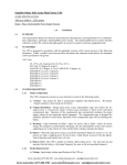
INTRODUCTION
The MINUTEMAN series Uninterruptible Power Supply (UPS) has been designed to be
maintenance-free, and to provide years of excellent service. It will provide superior power
protection for personal computers, telephone systems, and other critical equipment, against all
commercial power anomalies. Output waveform is a Synchronized Sinewave. Both lamp and
audible alarms indicate UPS and commercial power status at all times. Other features include:
External battery pack options for extended battery runtime.
Quiet operation
Excellent non-linear current capability
LAN communications port (optional)
RECEIVING INSPECTION
SAVE THE PACKING MATERIALS!
Remove and inspect the unit for shipping damage. If damage is found immediately notify the
carrier and your dealer. If no damage is found save both the shipping container and the packing
foam in case of a later need to return the unit to the factory or to ship it to another location.
WARRANTY REGISTRATION
Complete the warranty registration card provided and mail it within ten days of receipt to register
your warranty. Failure to register your warranty renders it non-valid.
IMPORTANT SAFETY INSTRUCTIONS
SAVE THESE INSTRUCTIONS
Read this manual carefully before operating the UPS. All instructions should be
followed during installation and maintenance of the UPS and batteries.
These UPS units are intended for use in a temperature-controlled, indoor area free of
conductive contaminants.
CAUTION -- UPS units use batteries for generation of AC voltages, so output receptacles
may be electrically hot even when UPS is not connected to commercial power. All repairs
should be performed by trained service personnel, since an electrical shock hazard exists.
CAUTION -- Do not remove the cover: there are no user-serviceable parts inside.
CAUTION -- To prevent electrical shock, the 3-wire plug provides earth ground for the UPS
chassis. Plug the UPS into a 3-wire grounding type commercial receptacle with grounding
conductor connected to earth ground at the service equipment. Removal of the ground pin
from the plug or use of a 3 wire-to-2 wire adapter will defeat this safety feature and may result
in a shock hazard. Additionally, if the plug is removed to simulate a power failure (not
recommended), do not touch the plug conductors or the chassis while the plug is removed.
1
CAUTION -- Do not allow water or any foreign object to enter the UPS. In case this occurs,
immediately turn the unit power switch off and unplug the MINUTEMAN from the commercial
receptacle.
Servicing of batteries should be performed or supervised by personnel knowledgeable of
batteries and the required precautions. Keep unauthorized personnel away from the
batteries.
When replacing UPS batteries, use the same number of sealed lead-calcium rechargeable
batteries with the same voltage and ampere-hour ratings as those in the UPS or battery pack.
These batteries have pressure-operated safety vents.
CAUTION -- Do not dispose of batteries in a fire. They may explode.
CAUTION -- Do not open or mutilate batteries. Released electrolyte is harmful to the skin
and eyes and may be toxic.
CAUTION -- Although battery system voltages are only 24 or 48 volts, battery systems can
still present a risk. The current capability of a battery is sufficient to burn wire or tools very
rapidly, producing molten metal. Observe these precautions when working on batteries:
1. Turn the UPS off and disconnect it from the wall outlet prior to connecting or
disconnecting battery terminals;
2. Remove watches, rings or other metal objects;
3. Use tools with insulated handles;
4. Wear protective gloves and eyewear;
5. Do not lay tools or other metal parts on top of batteries.
SELECTION OF UPS LOCATION
Select a location that will provide air circulation for the UPS at all times. Do not restrict
airflow in any way.
Avoid locations near heating devices.
Avoid locations near water or excessive humidity.
Avoid locations where the unit is exposed to direct sunlight.
Route power cords so they can not be walked on or damaged.
2
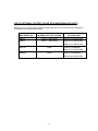
USE OF EXTERNAL BATTERY PACKS WITH MINUTEMAN UPS UNITS
Following is a table which shows the battery packs (BP) which can be used with each Minuteman
UPS without any output power derating.
MINUTEMAN UPS
INTERNAL BATTERY SYSTEM
BP TO BE USED
MM450
24VDC, 7 AMP-HOUR
BP24V10 (10 AMP-HOUR)
MM850
48VDC, 7 AMP-HOUR
BP48V10 (10 AMP-HOUR)
BP48V17 (17 AMP-HOUR)
MM1300
NONE
BP48V10 (STANDARD)
BP48V17 (17 AMP-HOUR)
MM2000
NONE
BP48V17 (STANDARD)
BP48V34 (34 AMP-HOUR)
3
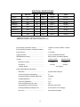
ELECTRICAL SPECIFICATIONS
MODEL #
RATED OUTPUT
(WATTS)
FREQ
(Hz)
INPUT
(VAC/A)
OUTPUT
(VAC/A)
BATTERY SYSTEM
(VDC)
MM450
315
60
120/3.9
120/2.6
24 (INT)
MM850
600
60
120/7.1
120/5.0
48 (INT)
MM1300
900
60
120/10.8
120/7.6
48 (BP)
MM2000
1400
60
120/16.6
120/11.7
48 (BP)
*MM2000
1400
60
120/12.0
120/11.7
48 (BP)
MM2000/2
1400
50
220/9.2
220/6.4
48 (BP)
✝MM2000/2U
1400
60
208/9.6
208/6.7
48 (BP)
1400
60
240/8.3
240/5.8
48 (BP)
* MM2000 Specifications if optional 5-15P plug is used.
✝ MM2000/2U available in both 208VAC and 240VAC models.
Input Voltage (AC Mode Function) ……………..
120VAC ± 15VAC; 220VAC ± 30VAC
Input Frequency Deviation for Synchronization.
± 5%
Inrush Current …………………………………….
1.5x Rated
Surge Protection ………………………………….
3-way, meets IEEE STD 587
RFI/EMI/Noise Filtering …………………………..
Both Common and Normal Modes
Transfer ……………………………………………
120VAC UNITS
220VAC UNITS
Brownout Transfer ……………………………
102VAC
190VAC
AC Return ……………………………………..
107VAC
200VAC
Transfer Speed ……………………………….
2ms Typical
Inverter Mode (Backup Operation)
Waveform ……………………………………..
Synchronized Sinewave
Crest Factor (Non-Linear Mode) ……………
3:1
Overload Capacity (50mSEC Maximum) ….
3x Rated
Voltage Regulation …………………………..
± 5%
Frequency Regulation ……………………….
DC-to-AC Efficiency (Full Load) ……………
± 1%
70%
Overload/Short Circuit Protection ………….
Electronic and Fused
Discharged Battery Recharge Time ……….
8 Hours (95% of Full Charge)
Run Time ……………………………………...
See Chart and Graphs
4
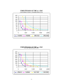
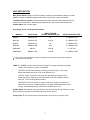
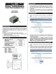
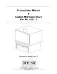
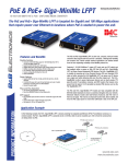
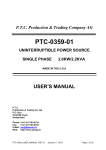
COMPUTER BACK-UP TIME vs. LOAD
Internal Battery System or Standard Battery Pack
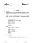
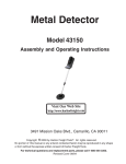
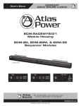
COMPUTER BACK-UP TIME vs. LOAD
UPS with Optional Battery Pack
5
PHYSICAL SPECIFICATIONS
MODEL #
NET WEIGHT
(LBS)
SHIPPING WEIGHT
(LBS)
DIMENSIONS
(L x W x H) (")
MM450
35.6
39
14 x 12.2 x 7.2
MM850
59.5
64
17.1 x 12.2 x 7.2
MM1300
46.9
52
17.1 x 12.2 x 7.2
MM2000
59.0
64
17.1 x 12.2 x 7.2
Operating Temperature ………………………………0ºC to 40ºC (32ºF to 104ºF)
Storage Temperature …………………………………-15ºC to 40ºC (5ºF to 104ºF)
Relative Humidity …………………………………….. 95% Max., Non-Condensing
Maximum Altitude Without Derate ………………….. 15,000 Ft.
Acoustic Noise ……………………………………….. Less than 60dB @ 3'
TYPICAL RUNTIME vs. LOAD (MINUTES)
COMPUTER
MM450 W/
MM850 W/
MM1300 W/
MM2000 W/
LOAD
INT BAT
BP24V10
INT BAT
BP48V10
BP48V10
BP48V17
BP48V17
BP48V34
100VA
104
346
---
---
---
---
---
---
200VA
34
112
98
319
---
---
---
---
300VA
17
58
49
158
152
259
---
---
450VA
9
30
24
78
72
122
144
351
600VA
---
---
15
48
42
71
84
206
850VA
---
---
8
26
22
37
44
108
1000VA
---
---
---
---
16
28
33
80
1300VA
---
---
---
---
10
17
20
49
1600VA
---
---
---
---
---
---
14
33
2000VA
---
---
---
---
---
---
9
22
6
UNIT DESCRIPTION
Main Power Switch: Turns on all UPS functions, except the internal battery charger on model
MM450. Charger on MM450 operates when UPS is connected to commercial power.
Test/Alarm Silencer Switch: Depressing this switch while in the AC mode causes the UPS to
switch to the Inverter mode. Depressing the switch while in the Inverter mode silences the
Audible Alarm until it is reset again.
Input Plugs, Fuses, and Output Receptacles:
INPUT PLUG
INPUT FUSE OR
CIRCUIT BREAKERS (CB)
OUTPUT RECEPTACLES
MM450
NEMA 5-15P
5A
4 -- NEMA 5-15R
MM1300
NEMA 5-15P
12A CB
4 -- NEMA 5-15R
MM850
NEMA 5-15P
8A
4 -- NEMA 5-15R
MM2000
NEMA L5-30P
20A
*4 -- NEMA 5-15R
✝Opt. Int.
10A CB
4 -- IEC 320
NEMA L6-30P
10A CB
*2 -- NEMA L6-30R
MODEL #
MM2000/2
MM2000/2U
* These units are also available with several combinations of locking and straight blade receptacles.
✝
Optional International Plugs
LEDS: AC NORMAL: Green when commercial voltage is in range and present, provided
battery circuit breaker is closed; off otherwise.
BATTERY IN USE: Red while unit is running in Inverter mode. In AC mode,
blinks when batteries are low or DC circuit breaker is off.
OUTPUT LOAD: Functions in AC mode only, providing an indication of the
actual output load. Each green LED represents 1/9 of total available output of
each unit. The red LED signifies overload.
BATTERY STATUS: Functions in Inverter mode only, providing a measure of
battery time remaining. As battery begins to run down, LEDs extinguish from left
to right. At low battery warning, only the two red LEDs are still on.
Audible Alarm: Sounds after a ten second delay every two seconds during inverter run mode.
Alarm frequency changes at low battery warning to two per second.
Cooling Fan: All units are forced air-cooled; however, fan runs only in Inverter mode.
7
INSTALLATION AND TEST
NOTE: If a Battery Pack is used with this UPS, refer first to the Battery Pack Owner's
Manual Installation Procedure.
1.
Ensure that the UPS power switch is "Off" ("
" position). Plug the UPS Power Plug into a
grounded commercial power receptacle with proper supply voltage and frequency.
2. Turn the DC Breaker Switch on.
3. Turn the UPS Power Switch "On" ("I" position). With commercial voltage present and in
range, the UPS will come on in the AC mode after a short delay.
4. Press and hold the Test/Alarm Silencer button for approximately 30 seconds: the AC
NORMAL LED will extinguish. The BATTERY IN USE LED will light, the BATTERY STATUS
LED's will light and the Audible Alarm will sound after a short delay. Release the Test/Alarm
Silencer Button and the UPS will return to the AC Normal mode after a short delay. AC
NORMAL LED will be on and all other indicators off.
5. Verify that the power requirements (VA & watts) of the equipment to be protected are within
the capacity of the UPS. Plug in and turn on the various loads. Momentarily press the Test
Button and verify proper UPS operation.
NOTE: If any condition experienced during the above test procedure was not as
described, refer to the UPS Problem Chart in the back of this manual.
OPERATION
The UPS loads may be controlled by the UPS Power Switch if desired. For Model MM450, the
battery charger functions with the Power Switch on or off. For other models, the Power Switch
must be on for battery charge; consequently, these units may need to remain on overnight if
several power outages occurred during the day.
When a brownout, power interruption, power outage or over-voltage condition occurs, the alarm
will sound and the BATTERY IN USE light indicator will glow, indicating that commercial power is
lost or unacceptable and MINUTEMAN is now supplying power to your system. With a slower
intermittent audible alarm (approximately once every two seconds) and one or more green
BATTERY STATUS indicator lights on, the unit is in the normal Inverter mode (BATTERY
OPERATION). When the alarm sounds at more rapid intervals (approximately two per second)
and all green BATTERY STATUS lights extinguish, about two minutes of battery power remain. If
you have not already downloaded you system and turned it off, you must do so at this time. Then
the MINUTEMAN Power Switch should be turned off to prevent further battery discharge.
When commercial power returns, switch the MINUTEMAN power switch to the "On" position if it
was turned off previously. The green indicator light will come on after a short delay. Return your
system to operation, and the MINUTEMAN system will automatically recharge the internal
batteries during system operation.
Since most commercial power outages are of short duration, commercial power will probably be
restored before the two-minute warning. IF COMMERCIAL POWER RETURNS BEFORE THE
WARNING SIGNAL, THERE IS NO NEED TO SHUT DOWN THE SYSTEM AT ALL. The
MINUTEMAN will switch back to normal AC operation automatically.
8
During normal AC operation, the MINUTEMAN Unit will quietly protect your system from power
surges, voltage spikes and noise interference. No alarms will sound and the green indicator light
will remain on during this operation.
SYSTEM BATTERIES
The internal batteries used in the MINUTEMAN UPS UNITS are sealed, maintenance-free, leadacid, with electrolyte totally absorbed in the plates and separator material. For maximum life,
battery temperature should be kept as cool as practical indoors, and at proper trickle charge
voltage.
Expected battery service is three to six years at 85ºF. For optimum performance, batteries
should be replaced after about three years. Replacement batteries can be purchased from Para
Systems, Inc. or from your local distributor or dealer. If the UPS is to be stored, allow the
batteries to fully charge for 24 hours; then store the unit in a cool, dry location. For extended
storage, recharge the batteries every four months. When the batteries are replaced, take the
used batteries to a recycle center for proper disposal and reclamation of the lead.
UPS MONITORING CONFIGURATIONS
All models provide an optional UPS monitoring capability (model suffix "K") which will allow direct
interface with many different computer operating systems. This capability permits an unattended,
orderly shut down of the computer system when commercial power is lost for a long period.
Some configurations also provide for a shut down of the UPS after the computer has been shut
down, thereby conserving UPS battery capability exists. Contact Para Systems sales department
for a more complete, up-to-date list.
Para Systems also offers its own software package "Network Manager," which functions with
Novell, UNIX-based, OS/2 and Macintosh operating systems. Network Manager offers many
advantages over existing UPS monitoring packages.
Finally, for systems which do not have UPS interface capabilities, user software can be written to
read UPS status and provide for system shut down. Software specialists should contact Para
Systems, Inc. for more information. The standard UPS DB9 PIN out is provided below for your
information.
UPS DIRECT INTERFACE CONFIGURATIONS
*Novell for AT compatible computers
Novell for PS/2 computers with mouse port connector
Microsoft LAN Manager or Microsoft NT
LANtastic
AS/400 Systems 9402/9404/9406
* This interface configuration functions with existing Novell UPS monitoring board, SS Keycard or
Disk Coprocessor Board. Para Systems Monitoring Board (MB1) is available for new installations
which do not already have an add-on monitoring board.
9
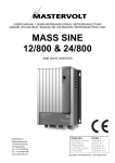
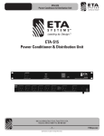
UPS DB9 PIN OUT
Pin 1 Not used
Pin 2 UPS simulates a relay closing (open collector transistor) between Pins 2 and 4 at
utility fail.
Pin 3 Not used.
Pin 4 Common ground return (for pins 2,5, and 6).
Pin 5 UPS simulates a relay closing (open collector transistor) between Pins 5 and 4 at
low battery warning.
Pin 6 User sends a RS232 high level (>+3V) to turn off the UPS (works only during
inverter operation). UPS returns to AC mode when commercial power is restored.
Pin 7 Signal ground.
Pin 8 Reserved.
Pin 9 Reserved.
SERVICE
If any problems are observed with you MINUTEMAN UPS, contact your supplier or Para Systems
customer service department. Prior to calling please write down and be prepared to discuss UPS
status indication, and if the UPS supplies power -- either in Inverter or AC mode. A chart to assist
in locating some common problems appears on the last page.
Do not remove the unit cover, or attempt any service. There are no user-serviceable components
inside. Unauthorized service will void the warranty.
POLICY AND INSTRUCTIONS
FOR RETURN OF PRODUCT TO PARA SYSTEMS, INC.
If the UPS must be returned to Para Systems, Inc. for any reason:
1. Call Para Systems at (972) 446-7363 and ask for Customer Service.
2. Describe the problem or reason for return and you will be given a Return Material
Authorization Number (RMA #). This number must be placed on the shipping carton,
preferably on the return shipping label. The RMA # on the carton will ensure prompt handling
when received at Para Systems, Inc.
3. Pack the unit for shipment in the original carton and foam as received. Other packaging
methods can result in damage to the unit. Remember to pack the power cord supplied with
the UPS in the carton.
4. Be sure to enclose the name and telephone number of the person who can authorize repair
charges. Also include the address where you want the product returned.
10
5. Send the UPS freight prepaid to Para Systems headquarters. C.O.D. shipments will no be
accepted.
6. If repair is Para Systems' responsibility, per the warranty, there will be no repair charge. The
UPS will be repaired and returned freight prepaid, provided the UPS was returned in the
original shipping carton and foam. If other packing methods result in shipping damage, repair
will be at your expense. If the packaging is not deemed usable for UPS return, there will be a
$10 charge for a new box and foam.
7. If UPS repair is not Para Systems' responsibility, you will be advised of the estimated charges
by telephone for your authorization. Should you choose not to have the UPS repaired, there
will be repair estimate charge of $20. The UPS will be returned C.O.D. for either the repair
amount or the estimated cost, plus shipping and handling.
UPS PROBLEM CHART
PROBLEM
When UPS Power Switch is
turned on, UPS stays in
Inverter mode.
POSSIBLE CAUSE
Input fuse blown or input
breaker tripped.
No commercial power at wall
receptacle or commercial
voltage too low or too high.
ACTION TO TAKE
Check fuses and replace if
blown, or reset breaker if
tripped.
Verify power is available and
voltage is in range.
UPS comes on in AC mode,
but no AC NORMAL LED
(green) and BATTERY IN USE
LED (red) blinks.
DC breaker is off or tripped.
Switch breaker off and back
on.
Backup time is considerably
less than expected; battery
charge condition is unknown.
Load is greater than
estimated.
Check and verify connected
load.
Batteries are not fully charged,
or weak.
Recharge batteries for 8 hours
and repeat backup test.
Charger has failed, or
batteries are bad.
Call Para Systems for service.
Backup time is considerably
less than expected at the end
of a battery recharge cycle (8
hours), and load is verified.
11
PARA SYSTEMS, INC.
1455 LeMay, Carrollton, TX 75006
Tel: (972) 446-7363
Fax: (972) 446-9011
LIMITED PRODUCT WARRANTY
PARA SYSTEMS, INC. (PARA SYSTEMS) warrants that this product will be free from defective material and
workmanship for a period of two years from the date of the original retail purchase by the end user provided
that the warranty registrations card is completed and returned PARA SYSTEMS within ten (10) days of
purchase. PARA SYSTEMS or its designated representative will repair, or at PARA SYSTEMS' option,
replace any product that has been returned by the purchaser and is confirmed by PARA SYSTEMS to be
defective.
This warranty shall be null and void if this product has been altered, opened without authorization, misused
or damaged by accident, misapplication, abuse, fire, flood or other disaster.
PARA SYSTEMS SHALL NOT BE LIABLE FOR DIRECT, INDIRECT, INCIDENTAL, CONSEQUENTIAL,
OR OTHER TYPES OR DAMAGES RESULTING FROM THE USE OF THIS PRODUCT OTHER THAN
THE LIABILITY STATED ABOVE. THIS WARRANTY IS IN LIEU OF ANY OTHER WARRANTIES
EXPRESSED OR IMPLIED, INCLUDING BUT NOT LIMITED TO, THE IMPLIED WARRANTIES OF
MECHANTABILITY OR FITNESS FOR A PARTICULAR PURPOSE.
MINUTEMAN PLATIMUM PROTECTION PLAN
LIMITED WARRANTY
In addition to the Product Warranty stated above, Para Systems, Inc. also warrants to the original purchaser
of the Minuteman products that all equipment connected to and powered by the UPS and registered under
the Minuteman Platinum Protection Plan shall be protected from damage caused by AC power surges,
subject to the following terms and conditions. Para Systems or its designated representative will, at Para
Systems' option, repair or replace any equipment so damaged, provided the cost of repair or replacement of
the equipment does not exceed twenty-five thousand dollars ($25,000).
TERMS AND CONDITIONS
1.
The UPS and connected equipment must be properly installed per the UPS Owner's Manual and in
compliance with all applicable electrical and safety code. Extension cords and power adapters are not
to be used.
2.
This warranty applies only to the original end user purchaser, who must register the UPS and
connected equipment within then (10) days of receipt.
3.
This warranty gives the purchaser specific legal rights, and the purchaser may also have other
unspecified rights which may vary from state to state.
4.
A finding will be issued by Para Systems within sixty (60) days or receipt of the affected Minuteman
unit/units and all documentation contained in the Minuteman Platinum Protection Plan Claims Packet.
A notice of the finding will be provided to the purchaser.
5.
This warranty does not cover: a.) any damage to any connected equipment resulting from any cause
other than AC power surge, as defined by IEEE Standard 587, which was transmitted through the UPS
to the connected equipment; b.) loss of data, software, business profits, claims by third parties and
other incidental damages even if Para Systems is advised of the possibility of such damages in
advance.
6.
This warranty shall be null and void if the Minuteman product is altered, opened without authorization,
misused or damaged by accident, misapplication, abuse, fire, flood or other disaster.
PLEASE KEEP THIS DOCUMENT FOR YOUR RECORDS
Model # _______________________ Date Purchased __________________________
12