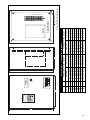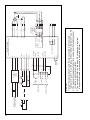
1
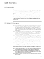
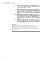
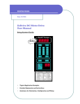
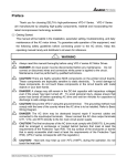
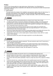
Zenith Pumps ZVD Vector Drive
®
Installation
And Operation
Manual
AC Vector Motor
Speed Controller
Table of Contents
1 ZVD Description . . . . . . . . . . . . . . . . . . . . . . . . . . . . . . . . . . . . . . . . . . . 1-1
1.1 Introduction . . . . . . . . . . . . . . . . . . . . . . . . . . . . . . . . . . . . . . . . . . . . . . . . . . . . . . . . . . . . . . . 1-1
1.2 General Information
.......................................................
1-1
Table 1-1 ZVD Standard Specifications . . . . . . . . . . . . . . . . . . . . . . . . . . . . . . . . . . . . . . . . . . 1-2
2. ZVD Installation and Wiring . . . . . . . . . . . . . . . . . . . . . . . . . . . . . . . . . 2-1
2.1 Installation . . . . . . . . . . . . . . . . . . . . . . . . . . . . . . . . . . . . . . . . . . . . . . . . . . . . . . . . . . . . . . . . 2-1
2.1.1 NEMA 1 Standalone
.................................................
2-1
2.1.2 NEMA 12 . . . . . . . . . . . . . . . . . . . . . . . . . . . . . . . . . . . . . . . . . . . . . . . . . . . . . . . . . . . . 2-1
2.2 Wiring . . . . . . . . . . . . . . . . . . . . . . . . . . . . . . . . . . . . . . . . . . . . . . . . . . . . . . . . . . . . . . . . . . . . . 2-1
2.2.1 General . . . . . . . . . . . . . . . . . . . . . . . . . . . . . . . . . . . . . . . . . . . . . . . . . . . . . . . . . . . . . 2-1
2.2.2 NEMA 12 . . . . . . . . . . . . . . . . . . . . . . . . . . . . . . . . . . . . . . . . . . . . . . . . . . . . . . . . . . . . 2-2
3. ZVD Program Requirements . . . . . . . . . . . . . . . . . . . . . . . . . . . . . . . . 3-1
3.1 General . . . . . . . . . . . . . . . . . . . . . . . . . . . . . . . . . . . . . . . . . . . . . . . . . . . . . . . . . . . . . . . . . . . 3-1
3.2 Accessing Program Codes
................................................
3.3 Standard Program Code Changes
.........................................
3-1
3-1
4. ZVD Operation . . . . . . . . . . . . . . . . . . . . . . . . . . . . . . . . . . . . . . . . . . . . . 4-4
4.1 Local Keypad Operation . . . . . . . . . . . . . . . . . . . . . . . . . . . . . . . . . . . . . . . . . . . . . . . . . . . 4-1
4.1.1 Entering Setpoint
....................................................
4-1
4.1.2 Starting the ZVD . . . . . . . . . . . . . . . . . . . . . . . . . . . . . . . . . . . . . . . . . . . . . . . . . . . . . 4-1
4.1.3 Stopping the ZVD. . . . . . . . . . . . . . . . . . . . . . . . . . . . . . . . . . . . . . . . . . . . . . . . . . . . 4-1
4.1.4 Jogging the ZVD
....................................................
4-1
4.1.5 Changing Motor Rotation . . . . . . . . . . . . . . . . . . . . . . . . . . . . . . . . . . . . . . . . . . . . . 4-1
4.1.6 Monitoring ZVD Operations
..........................................
4-1
4.1.7 Faults . . . . . . . . . . . . . . . . . . . . . . . . . . . . . . . . . . . . . . . . . . . . . . . . . . . . . . . . . . . . . . . 4-2
4.2 Remote Operation . . . . . . . . . . . . . . . . . . . . . . . . . . . . . . . . . . . . . . . . . . . . . . . . . . . . . . . . . 4-2
4.2.1 Setpoint . . . . . . . . . . . . . . . . . . . . . . . . . . . . . . . . . . . . . . . . . . . . . . . . . . . . . . . . . . . . . 4-2
4.2.2 Operation Command Control (Run/Stop). . . . . . . . . . . . . . . . . . . . . . . . . . . . . . 4-2
4.2.3 Remote Monitoring ZVD Operation. . . . . . . . . . . . . . . . . . . . . . . . . . . . . . . . . . . . 4-2
5. ZVD Troubleshooting and Fault Information
.....................
5-1
Appendix
A
ZVD Part Numbers
B
ZVD Program Code 00 – 05 Examples . . . . . . . . . . . . . . . . . . . . . . . . . . . . . . . . . . . . . . B-1
C
ZVD Program Codes
D
ZVD Summary of Default Program Codes . . . . . . . . . . . . . . . . . . . . . . . . . . . . . . . . . . . D-1
E
Drawing S - 52
........................................................
......................................................
............................................................
A-1
C-1
E-1
i
1. ZVD Description
1.1 Introduction
This manual contains easy to follow information and procedures required to complete
the initial installation, wiring, and startup operation for the ZVD AC Vector Drive. Be
sure to observe all WARNINGS, CAUTIONS, and NOTES prior to proceeding with a
particular task.
Note: The standard ZVD Vector Drive is prepackaged in a NEMA 12 control cabinet.
The controller is mounted and all internal cabinet wiring is complete. The unit is programmed according to customer specifications. All that is required of the customer
is to make field wiring connections. The customer should become familiar with this
manual, particularly with regard to input/output selections and wiring techniques to
avoid electromagnetic interference (EMI) noise pickup, damage to equipment, and
personal injury.
1.2 General Information
1.2.1 The standard ZVD AC Vector Motor Drive and Speed Control consists of an AC
vector drive, mounted in a NEMA 12 control cabinet. The drive is mounted on
the sub-panel and pre-wired to a terminal strip for customer terminations. The
keypad from the drive has been relocated to the cabinet door via a connector
cable. A Pulse Generator card has been installed in the drive to provide closed
loop feedback.
1.2.2 The standard ZVD Vector Drive is available in four 230 VAC, 3 phase models (1,
2, 3, and 5 HP) and in four 460 VAC, 3 phase models (1, 2, 3, and 5 HP). The
control cabinet size varies, depending on the horsepower rating of the drive.
See the chart on page E-1 for cabinet sizes.
1.2.3 A standalone NEMA 1 version of the ZVD Vector Drive(s) is also available with
the Pulse Generator card installed. The standalone ZVD is not supplied with a
cable for use in remotely locating the keypad. The cable must be ordered separately. Consult the factory for details.
1.2.4 For 380 VAC input voltage, use the corresponding 460 VAC drive version. If full
load at 380 VAC is required, use the next higher power drive and motor (e.g., if
operating conditions require 1 HP and the input voltage is 380 VAC, specify a 2
HP drive and motor).
1.2.5 In Vector mode, the ZVD Vector Drive provides a closed loop accuracy of 0.1%
of base speed under constant load. Closed loop feedback must be provided by
a 120 PPR (minimum) Hall Effect feedback sensor or encoder.
1.2.6 A vector (inverter) duty AC motor is required. Constant torque turndown of the
motor is 100:1.
1.2.7 The ZVD Vector Drive meets UL, CUL (CSA), and the CE low voltage directive.
With the optional EMI filter, the drive also meets the CE EMI requirements.
1.2.8 In the event the motor drive assembly has to be located in a hazardous location, an optional intrinsically safe barrier is available to install in the ZVD Vector
Drive cabinet to limit sensor current to safe levels.
1.2.9 Appendix A contains a list of ZVD Vector Drive options and auxiliary equipment
by part number.
1-1
Table 1-1. ZVD Standard Specifications
Rated Input Voltage:
230 VAC: 180 – 264 VAC, 3 Phase
HP Rating:
1 HP
2 HP
3 HP
5 HP
Rated Input Current:
5.7A
7.6A
14.0A
20.6A
Rated Output Current:
5.0A
7.0A
11.0A
17.0A
Rated Input Voltage:
460 VAC: 342 – 528 VAC, 3 Phase
HP Rating:
1 HP
2 HP
3 HP
5 HP
Rated Input Current:
3.2A
4.3A
5.9A
11.2A
Rated Output Current:
2.7A
4.2A
5.5A
8.5A
Rated Input Frequency:
47 to 63 Hz
Rated Output Voltage:
Proportional to Input Voltage
Rated Output Frequency:
0.1 to 400 Hz
Environment:
Ambient Temp: -10° C to 50° C
Storage: - 20° C to 60° C
Relative Humidity:
90 %, Non-condensing
Vibration: 1 G to 20 Hz, 0.6 G above 20 Hz
Cooling:
Natural, air cooled
NEMA Ratings:
Standalone: NEMA 1
Keypad: NEMA 4
Enclosure: NEMA 12
Classifications:
UL, CUL (CSA), CE (with optional EMI filter)
Closed Loop Accuracy:
0.1% Base Speed, Constant Load
Turndown:
100:1 Constant Torque, Vector Mode
Tuning:
PID, Auto Detection of Motor in Vector Mode
Password Protection:
Yes
Fault Detection:
Self-test, Over-voltage, Over-current, Under-voltage,
Overload, Overheating, External Fault, Electronic Thermal,Ground Fault
Analog:
Input: 0 – 10 VDC or 4 – 20 mA
Output: 0 – 10 VDC
Setpoints:
User Defined
Keypad, 0.01 Hz Resolution
Analog, 0.1 Hz Resolution
Control Inputs:
Five Standard Digital Inputs
Six Multi-function Digital Inputs
One Counter Input (250 Hz max)
Feedback Sensor (with PG card installed)
Control Outputs:
Three Open Collector Multi-function Outputs
One Form C Relay Multi-function Output
Retransmission of Feedback Frequency
PLC Function:
15 Step Function (Speed, Time, Direction)
Keypad Controls:
Fwd, Rev, Stop, Jog, Program, Monitor
Serial Communications:
RS-485, Modbus Protocol
Options:
Certified EMI filter to meet CE requirements
Intrinsically Safe Barrier
1-2
2. ZVD Installation and Wiring
2.1 Installation
The ZVD AC vector drive is sold in a NEMA 12 control cabinet and is intended to be
part of a Zenith Products Division fluid handling solution. For customers who desire to
mount the drive in their own cabinet, the ZVD is also sold as a standalone NEMA 1
drive.
2.1.1 NEMA 1 Standalone
If purchased as a NEMA 1 standalone drive, the location and installation of the ZVD
should adhere to the following constraints:
2.1.1.1 Do not mount the ZVD drive near heat-radiating elements or in
direct sunlight.
2.1.1.2 Do not install the ZVD drive in a place subjected to high tem-
perature, high humidity, excessive vibration, corrosive gasses
or liquids, or airborne dust or metallic particles.
2.1.1.3 Mount the ZVD drive vertically and do not restrict the air flow to
the heat sink fins.
2.1.1.4 Allow sufficient space around the unit for heat dissipation.
Approximately 6 inches should be allowed above and below
the drive and 2 inches on each side.
2.1.2 NEMA 12
If purchased as a drive in a NEMA 12 cabinet, the location and installation of the ZVD
should adhere to the following constraints:
2.1.2.1 Do not mount the NEMA 12 ZVD drive near heat-radiating
elements or in direct sunlight.
2.1.2.2 Do not install the NEMA 12 ZVD drive in a place subjected to
high temperature, high humidity, excessive vibration, corrosive
gasses or liquids, or water spray.
2.1.2.3 Mount the NEMA 12 ZVD drive vertically, allowing a minimum of
6 inches above and below the control panel and 2 inches
behind the panel for air flow and convection cooling.
2.2 Wiring
The ZVD drive will arrive with all internal wiring of the NEMA 12 cabinet complete, for
most customer requirements. The customer will be required to wire to the terminal strip
mounted inside the cabinet. If the customer desires to use some available functions of
the ZVD that are considered non-routine, the customer may have to wire to the ZVD,
itself. If the ZVD drive is ordered as a NEMA 1 standalone drive, the customer is
required to make all connections to the drive.
2.2.1
General
CAUTION: TO PREVENT PERSONNEL ELECTROCUTION OR DAMAGE TO THE
EQUIPMENT, MAKE SURE ALL POWER TO THE ZVD IS REMOVED BEFORE MAKING
ANY WIRING CONNECTIONS OR CHANGES.
Wiring practices must conform to applicable local electric codes and the National
Electric Code (NEC). If installed in a country outside the USA, wiring practices should
conform to the electric codes of the country the ZVD is installed in.
2.2.1.1 Input power to the control cabinet must be supplied through an
appropriately sized circuit breaker or fused disconnect that is
within easy reach of the cabinet.
2-1
2.2 Wiring (continued)
2.2.1.2 The control cabinet ground must be a single point termination
and be at a resistance of less than 1 ohm with relation to true
earth. All grounds within the control cabinet must be connected
to the single point ground termination.
2.2.1.3 High voltage wiring (> 50 V) must be run in separate conduit
from low voltage (<50 V) or signal wiring. If run parallel to each
other, high voltage wiring should be separated from low voltage
and signal wiring by 12 inches or as much as physically possible. If they must cross each other, they should cross perpendicularly.
2.2.1.4 Shielded cable should be used for signal wiring to prevent
electrical noise contamination. The shield should be terminated
at the ZVD only. (NOTE: Terminating the shield at both ends
causes ground loops and defeats the purpose of using shielded
cable).
2.2.1.5 Low voltage wiring making long runs outside a control cabinet
should use shielded cable also. Shield termination should be at
the end of the cable connected to the equipment requiring the
most noise protection. (NOTE: In some cases, this may be the
PC or PLC, rather than the ZVD).
2.2.2 NEMA 12
Wiring connections for the NEMA 12 enclosure are shown on page E-3.
NOTE: The NEMA 12 enclosure is not provided with any pre-punched conduit holes.
The customer is required to punch holes in the enclosure to facilitate field wire
entrance. The customer should ensure that the entrance holes and conduit conform to
local wiring codes.
2-2
3. ZVD Program Requirements
3.1 General
The ZVD program codes are arranged in groups. A program code is designated by
its group number, followed by a dash, and then its individual number within that
group. For example, the code 05 – 03 indicates it is the third code in the fifth group.
For a full discussion on groups and codes, consult the full code listing.
3.2 Accessing Program Codes
3.2.1
To access the program codes, press the PROG/DATA key. The display shows
a number on the left. This is the group number. To go to another group, use
the UP and DOWN arrows.
3.2.2
When the desired group is in the display, press the PROG/DATA key again. A
code number shows up on the right side of the display. Scroll to the correct
code using the UP and DOWN arrows.
3.2.3
When the desired group and code are in the display, press the PROG/DATA
key a third time. The display now shows the value in that code. To change the
value, use the UP and DOWN arrows. If the number in the display is larger
than one digit, the other digits may be accessed using the LEFT arrow.
3.2.4
Once the desired value has been entered in the code, press the PROG/DATA
key a fourth time. The display will show “End”, which means that the change
has been accepted. If it shows “Err”, the code cannot be changed at this
time. The reason may be that the drive is in a “RUN” condition and the code
cannot be changed until it is stopped. Some codes are “READ ONLY”, which
means that they cannot be changed under any conditions, such as codes 00
- 00 and 00 – 01.
3.3 Standard Program Code Changes
NOTE: The default program in the ZVD is sufficient for normal pump operation except
for a few codes, listed below. Changing the codes below should meet the needs of
most users. If other functions are desired from the ZVD, consult the full code listing.
Code 00 – 03 (Startup Display Selection) = 2 (User Defined Units, U)
Code 00 – 04 (Multi-function Display) = 11 (encoder RPM)
Code 00 – 05 (User Defined Coefficient) = ____________ (Maximum User Defined
Units/Code 01 – 00 (60.OO Hz))
NOTE: See Appendix B for examples
Code 00 – 09 (Operating Mode) = 3 (Vector with Feedback)
Choices: Volts/Hertz without Feedback (0), Volts/Hertz with Feedback (1),
Vector without Feedback (2), or Vector with Feedback (3)
Code 01 – 09 (Acceleration Rate in Seconds) = ____________ (Default is 10.0)
Code 01 – 10 (Deceleration Rate in Seconds) = ____________ (Default is 10.0)
Code 02 – 00 (Source of Frequency Command) = ____________ (Default is 0 (Keypad))
Choices: Keypad (0), Analog 0 – 10VDC (1), Analog 4 – 20 mA (2), or
RS-485 (4)
Code 02 – 01 (Source of Operation Command) = ____________ (Default is 0 (Keypad))
Choices: Keypad (0), External with keypad stop (1), or RS-485 with
keypad stop (3)
3-1
3.3 Standard Program Code Changes (continued)
Code 02 – 02 (Stop Method) = ____________ (Default is 0 (Ramp Stop))
Choices: Ramp Stop (0) or Fast Stop (1)
Code 02 – 03 (Carrier Frequency) = 12 (KHz)
NOTE: EMI and heat generation are directly affected by carrier frequency. Acoustical
noise is inversely affected by carrier frequency. If the motor is located in a
space in which acoustical noise is not bothersome, set Code 02 – 03 to 2 KHz.
Code 02 – 04 (Reverse Operation) = 1 (Disable Reverse)
Code 02 – 05 (Operation Control Modes) = ____________ (Default is 0 (Fwd/Stop))
Choices: One Contact Start/Stop (0) or Two Contacts Start and Stop (2)
Code 03 – 00 (Multi-function Output Terminal (Relay Output)) = ____________ (Default
is 8 (Fault Indication))
Choices: No function (0), AC drive operational (1), Maximum output frequency attained (2), Zero speed (3), Over-torque detection (4), Baseblock (B.B.) indication (5), Low voltage indication (6), Fault indication
(8), Desired frequency attained (9), PLC program running (10), PLC program step completed (11), PLC program completed (12), PLC program
paused (13), Terminal count value attained (14), Preliminary count value
attained (15), Heatsink overheat warning (19), AC drive ready (20), or
Emergency stop indication (21).
Code 03 – 05 (Analog Output Signal) = ____________ (Default is 0 (Analog frequency
meter))
Choices: Analog frequency meter (0), Analog current meter (1), Output
voltage (2), Output frequency (3), Motor output speed command (4), or
Output power factor (5)
Code 04 – 04 (Multifunction Input MI1) = 20 (Emergency Stop)
Code 04 – 05 (Multifunction Input MI2) = ____________ (Default is 0 (Disabled))
Choices: Disabled (0), Multi-step speed 1 (1), Multi-step speed 2 (2),
Multi-step speed 3 (3), Multi-step speed 4 (4), External reset (5),
Accel/Decel speed inhibit (6), Increase frequency (11), Decrease frequency (12), Counter reset (13), Run PLC program (14), Pause PLC program (15), Emergency stop (N.O.) (19), Emergency stop (N.C.) (20), or
External start command (23)
Code 06 – 00 (Over-Voltage Stall Prevention) = 0 (Disabled)
Code 06 – 01 (Over-Current Stall Prevention During Acceleration) = 250 (%)
Code 06 – 02 (Over-Voltage Stall Prevention During Operation) = 250 (%)
Code 06 – 06 (Thermal Overload Relay) = 1 (Constant Torque Motor)
Code 06 – 07 (Thermal Characteristic) = 120 (Seconds)
Code 07 – 00 (Motor Rated Current) = ____________ (Motor Rated Current / Drive
Rated Current (in %))
NOTE: The setting of this parameter is very important, particularly when the motor HP
is less than the maximum rating of the drive. This parameter protects the undersized motor from drawing too much current, and possibly being damaged. If
the calculated value is less than 40 %, which is the default of Code 07 – 01,
Code 07 – 01 must be set first.
Code 07 – 01 (Motor No-load Current) = ____________ (Motor No-load Current / Drive
Rated Current (in %))
3-2
3.3 Standard Program Code Changes (continued)
Code 07 – 02 (Torque Boost) = 0 (Code 00 - 09 = 2 or 3); = 8 (Code 00 – 09 = 0 or 1)
Code 07 – 04 (Number of Motor Poles) = 4 (Base Speed = 1800 RPM)
Code 07 – 05 (Motor Auto Detection) = 1, then press RUN (To Auto Detect Motor
Resistance); = 0 (Normal)
Code 07 – 06 (Motor Line-to-line Resistance) = ____________ (Auto Detect through or
Measure Using an Ohmmeter)
Code 07 – 10 (Current Limit) = 100 (Software Version 3.12 or later)
Code 10 – 08 (Feedback Signal Detection Time) = 5 (Seconds)
Code 10 – 09 (Transmission Fault Treatment) = 1 (Alarm and RAMP to stop)
Code 10 – 10 (PG Pulse Range) = ____________ (PPR of Feedback Sensor)
Code 10 – 11 (PG Input) = 1 (Single Phase Feedback)
Code 10 – 12 (Proportional Speed Control (P)) = 1.0 (Proportional Setting)
Code 10 – 13 (Integral Speed Control (I)) = .05 (Integral Setting)
Code 10 – 14 (Speed Control Output Frequency Limit) = 10.0 (Hz)
Code 10 – 15 (Feedback Display Factor (1800 rpm @ 60 Hz)) = ____________
Choices: 120 PPR sensor (125), 60 PPR sensor (250), or 30 PPR sensor
(500) (See Code 10 – 10)
NOTE: To reset all codes to factory defaults, set Code 00 – 02 = 10. Reprogram, as
above.
3-3
4. ZVD Operation
NOTE: For all references to wiring, refer to Chapter 2. For all references to programming codes, refer to Chapter 3.
4.1 Local Keypad Operation
4.1.1 Entering Setpoint
4.1.1.1 Press the MODE key until the F or U is lit on the left side of the
display.
4.1.1.2 If the F is lit, the setpoint will be entered in frequency. The
frequency range is from 0.01 Hz to the value of Code 01-00,
which for the standard setup is 60.00 Hz. A setting of 60.00 Hz
means that the motor will turn at 1800 RPM.
4.1.1.3 If the U is lit, the setpoint will be entered in user-defined units.
The unit is established by Code 00-05. The value in Code 00-05
represents 1.00 Hz, or 30 motor RPM.
4.1.2 Starting the ZVD
4.1.2.1 Press the RUN key. The motor will ramp up to set speed at the
acceleration rate entered in Code 01-09.
4.1.2.2 The LED labeled RUN will be lit.
4.1.3 Stopping the ZVD
4.1.3.1 Press the STOP/RESET key. The motor will ramp down at the
deceleration rate entered in Code 01-10.
4.1.3.2 The LED labeled RUN will flash during deceleration, and go off
when stopped.
4.1.3.3 The LED labeled STOP will be lit.
4.1.4 Jogging the ZVD
4.1.4.1 To enable JOG, the drive must be in a stopped condition.
4.1.4.2 Press the JOG key. The motor will run at the frequency entered
in Code 01–14 as long as the key is pressed. Releasing the
JOG key will cause the motor to stop.
4.1.4.3 The LED labeled JOG will be lit while the JOG key is pressed.
4.1.5 Changing Motor Rotation
4.1.5.1 Rotation direction is indicated by the LED labeled FWD or REV
being lit. NOTE: Code 02 – 04 enables or disables Reverse
(Normally disabled).
4.1.5.2 If Reverse is enabled, to change rotation, press the MODE key
until the direction is shown on the display. Using the UP or
DOWN arrow, change motor direction.
4.1.6 Monitoring ZVD Operation
4.1.6.1 Press the MODE key until the H is lit on the left side of the
display.
4.1.6.2 If the motor is running, the display will show the output to the
motor in Hz.
4.1.6.2.1 Pressing the LEFT arrow scrolls through a series of
parameters reflecting drive performance. These include
output current, output voltage, output power, DC BUS
voltage, power factor angle, torque ratio, counter value,
and PLC time.
4-1
4.1 Local Keypad Operation (continued)
4.1.6.3 Press the MODE key until no LED’s are lit on the left side of the
display. This is the multi-function display and will indicate the
parameter selected by Code 00 – 04.
4.1.6.3.1 If the action indicated in paragraph 4.1.6.2.1 has been
performed, the display will show the last parameter
viewed. Calling up Code 00 – 04 will reflect this new
parameter. NOTE: To view encoder RPM, Code 00 – 04
must be set back to 11.
4.1.7 Faults
4.1.7.1 Should a fault occur, the ZVD will stop and display the fault des-
ignation. See the Troubleshooting section for fault designations.
4.1.7.2 Once the fault has been cleared, press the STOP/RESET key to
clear the display and return to a ready condition.
4.2 Remote Operation
4.2.1 Setpoint
4.2.1.1 Select the method of supplying remote setpoint using Code 02–00.
4.2.1.2 For the method chosen above, wire according to page E-3.
4.2.1.3 Input the setpoint command.
4.2.2 Operation Command Control (Run/Stop)
4.2.2.1 Select the method of operation command control using Code 02–01.
4.2.2.2 If the method of control is using external contacts, select one
contact or two contact using Code 02 – 05.
4.2.2.3 For the method of control chosen, wire according to page E-3.
4.2.2.4 Provide the method of operation command control chosen.
4.2.3 Remote Monitoring ZVD Operation
4.2.3.1 Analog Output, 0 – 10 VDC.
4.2.3.1.1 Select the parameter to be monitored using Code 03 – 05.
4.2.3.1.2 Wire the analog output circuit according to page E-3.
4-2
5. ZVD Troubleshooting and Fault Information
The ZVD motor drive has a comprehensive fault diagnostic system that includes several
different alarms and fault messages. Once a fault is detected, the corresponding
protective functions will be activated to shut down the drive output. Below are the fault
descriptions for a fault shown on the digital keypad display. The four most recent faults
can be read on the digital keypad display (codes 06-08 through 06-11.
NOTE: After faults occur, press RESET to begin using the drive again.
Fault
Name
Fault Descriptions
The AC drive detects an abnormal
increase in current.
Corrective Actions
1. Check whether the motors horsepower
corresponds to the AC drive output power.
2. Check the wiring connections between the
AC drive and motor for possible short circuits.
3. Increase the Acceleration time.
4. Check for possible excessive loading
conditions at the motor.
IGBT protection
5. If there are any abnormal conditions when
operating the AC drive after short-circuit
being removed, it should be sent back to
manufacturer.
The AC drive detects that the
DC bus voltage has exceeded its
maximum allowable value.
1. Check whether the input voltage falls within
the rated AC drive input voltage.
2. Check for possible voltage transients.
3. Bus over-voltage may also be caused by
motor regeneration. Either increase the decel
time or add an optional braking resistor.
4. Check whether the required braking power
is within the specified limits.
The AC drive temperature sensor
detects excessive heat.
1. Ensure that the ambient temperature falls
within the specified temperature range.
2. Make sure that the ventilation holes are not
obstructed.
3. Remove any foreign objects on the heatsinks
and check for possible dirty heat sink fins.
4. Provide enough spacing for adequate
ventilation.
The AC drive detects that the DC
bus voltage has fallen below its
minimum value.
1. Check whether the input voltage falls within
the rated AC drive’s input voltage.
5-1
Fault
Name
Fault Descriptions
1. The AC drive detects excessive
drive output current.
Note: The AC drive can withstand up
to 150% of the rated current for
a maximum of 60 seconds.
Internal electronic overload trip
Corrective Actions
1. Check whether the motor is overloaded.
2. Reduce torque compensation setting as set
in Pr.7-02.
3. Increase the AC drive’s output capacity.
1. Check for possible motor overload.
2. Check electronic thermal overload setting.
3. Increase motor capacity.
4. Reduce the current level so that the drive
output current does not exceed the value set
by the Motor Rated Current Pr.7-00.
Motor overload. Check the parameter settings (Pr.6-03 to Pr.6-05)
1. Reduce the motor load.
2. Adjust the over-torque detection setting to an
appropriate setting (Pr.06-03 to Pr.06-05).
Communication Error
1. Check the connection between the AC drive
and computer for loose wires.
2. Check if the communication protocol is
properly set.
Over-current during acceleration:
1. Short-circuit at motor output.
2. Torque boost too high.
3. Acceleration time too short.
4. AC drive output capacity is too
small.
Over-current during deceleration:
1. Short-circuit at motor output.
2. Deceleration time too short.
3. AC drive output capacity is too
small.
Over-current during steady state
operation:
1. Short-circuit at motor output.
2. Sudden increase in motor loading.
3. AC drive output capacity is too
small.
5-2
1. Check for possible poor insulation at the output line.
2. Decrease the torque boost setting in Pr.7-02.
3. Increase the acceleration time.
4. Replace with the AC drive with one that has a
higher output capacity (next HP size).
1. Check for possible poor insulation at the output line.
2. Increase the deceleration time.
3. Replace with the AC drive with one that has a
higher output capacity (next HP size).
1. Check for possible poor insulation at the
output line.
2. Check for possible motor stall.
3. Replace with the AC drive with one that has
a higher output capacity (next HP size).
Fault
Name
Fault Descriptions
The external terminal EF-GND goes
from OFF to ON.
Corrective Actions
1. When external terminal EF-GND is closed,
the output will be turned off. (under N.O. E.F.)
2. Press RESET after fault has been cleared
Emergency stop.
Press RESET after fault has been cleared.
When the multifunction input terminals
(MI1 to MI6) stop, AC drive stops
any output.
Internal memory IC can not be
programmed.
1. Return to the factory.
Internal memory IC can not be read.
1. Return to the factory.
2. Check the EEPROM on the control board.
2. Reset drive to factory defaults.
Drive’s internal circuitry abnormal.
Return to the factory.
Hardware protection failure
Return to the factory.
Software protection failure
Return to the factory.
Auto accel/decel failure
1. Don’t use the function of auto
acceleration/deceleration.
Ground fault :
Ground fault :
The AC drive output is abnormal.
When the output terminal is grounded
(short circuit current is 50% more
than the AC drive rated current), the
AC drive power module may be
damaged. The short circuit protection
is provided for AC drive protection,
not user protection.
1. Check whether the IGBT power module is
damaged.
External Base Block.
1. When the external input terminal (B.B.) is
active, the AC drive output will be turned off.
AC drive output is turned off.
2. Check for possible poor insulation at the output line.
2. Disable this connection and the AC drive will
begin to work again.
AnLEr: analog feedback error
PGErr: PG feedback signal error
1. Check both parameter settings and wiring of
Analog/PC (Pr. 10-00).
2. Check for possible fault between system
reaction time and the feedback signal
detection time (Pr. 10-08).
5-3
APPENDIX A: ZVD Part Numbers
Standalone Part Numbers (NEMA 1)
Description
Part Number
1 HP, 230 VAC, 3 Phase . . . . . . . . . . . . . . . . . . . 68-16817-0108-0
NEMA 12 Part Numbers
with EMI filter installed
Description
Part Number
2 HP, 230 VAC, 3 Phase . . . . . . . . . . . . . . . . . . . 68-16817-0109-0
1 HP, 230 VAC, 3 Phase . . . . . . . . . . . . . . . . . . . 68-16814-0705-0
1 HP, 460 VAC, 3 Phase . . . . . . . . . . . . . . . . . . . 68-16817-0110-0
2 HP, 230 VAC, 3 Phase . . . . . . . . . . . . . . . . . . . 68-16814-0706-0
2 HP, 460 VAC, 3 Phase . . . . . . . . . . . . . . . . . . . 68-16817-0111-0
3 HP, 230 VAC, 3 Phase . . . . . . . . . . . . . . . . . . . 68-16814-0707-0
3 HP, 230 VAC, 3 Phase . . . . . . . . . . . . . . . . . . . 68-16817-0114-0
5 HP, 230 VAC, 3 Phase . . . . . . . . . . . . . . . . . . . 68-16814-0708-0
3 HP, 460 VAC, 3 Phase . . . . . . . . . . . . . . . . . . . 68-16817-0115-0
1 HP, 460 VAC, 3 Phase . . . . . . . . . . . . . . . . . . . 68-16814-0709-0
5 HP, 230 VAC, 3 Phase . . . . . . . . . . . . . . . . . . . 68-16817-0116-0
2 HP, 460 VAC, 3 Phase . . . . . . . . . . . . . . . . . . . 68-16814-0710-0
5 HP, 460 VAC, 3 Phase . . . . . . . . . . . . . . . . . . . 68-16817-0117-0
3 HP, 460 VAC, 3 Phase . . . . . . . . . . . . . . . . . . . 68-16814-0711-0
5 HP, 460 VAC, 3 Phase . . . . . . . . . . . . . . . . . . . 68-16814-0712-0
NEMA 12 Part Numbers
Description
Part Number
Auxiliary Part Numbers
1 HP, 230 VAC, 3 Phase . . . . . . . . . . . . . . . . . . . 64-16814-0693-1
Description
Part Number
2 HP, 230 VAC, 3 Phase . . . . . . . . . . . . . . . . . . . 64-16814-0694-1
Pulse Generator Card . . . . . . . . . . . . . . . . . . . . . 68-16818-0114-0
1 HP, 460 VAC, 3 Phase . . . . . . . . . . . . . . . . . . . 64-16814-0695-1
EMI Filter, 1 - 2 HP, 230/460 VAC . . . . . . . . . . 68-16818-0116-0
2 HP, 460 VAC, 3 Phase . . . . . . . . . . . . . . . . . . . 64-16814-0696-1
EMI Filter, 3 - 5 HP, 230 VAC
..............
68-16818-0117-0
3 HP, 230 VAC, 3 Phase . . . . . . . . . . . . . . . . . . . 64-16814-0699-1
EMI Filter, 3 - 5 HP, 460 VAC
..............
68-16818-0118-0
3 HP, 460 VAC, 3 Phase . . . . . . . . . . . . . . . . . . . 64-16814-0700-1
ZVD to Keypad Cable, 1 meter long . . . . . . . 68-17507-0049-0
5 HP, 230 VAC, 3 Phase . . . . . . . . . . . . . . . . . . . 64-16814-0702-1
ZVD to Keypad Cable, 2 meters long . . . . . . 68-17507-0052-0
5 HP, 460 VAC, 3 Phase . . . . . . . . . . . . . . . . . . . 64-16814-0703-1
ZVD to Keypad Cable, 3 meters long . . . . . . 68-17507-0053-0
ZVD to Keypad Cable, 5 meters long . . . . . . 68-17507-0054-0
Intrinsically Safe Barrier . . . . . . . . . . . . . . . . . . . 68-16509-0071-1
A-1
APPENDIX B: ZVD Program Code 00-05 Examples
Example (1): User Defined Units in Pump RPM
Given: Code 01 – 00 = 60 Hz
Motor RPM @ 60 Hz = 1800 RPM
Reducer Ratio = 21.420 : 1
Example (5): User Defined Units in Flow Rate (gm /
minute)
Given: Code 01 – 00 = 60 Hz
Motor RPM @ 60 Hz = 1800 RPM
Reducer Ratio = 22.585 : 1
Then: Pump RPM @ 60 Hz = 1800 / 21.420 = 84.03 RPM
Code 00 – 05 = Pump RPM / Code 01 – 00
Pump Capacity = 1.2 cc / revolution
Fluid Specific Gravity = 1.1 gm / cc
Code 00 – 05 = 84.03 / 60 = 1.40
Then: Pump RPM @ 60 Hz = 1800 / 22.585 = 79.699 RPM
Example (2): User Defined Units in Pump RPM
Given: Code 01 – 00 = 60 Hz
Motor RPM @ 60 Hz = 1800 RPM
Reducer Ratio = 5.091 : 1
Pump Flow Rate @ 60 Hz = 79.699 RPM x 1.2 cc/Rev
= 95.64 cc / minute
Pump Flow Rate in gm/min @ 60 Hz = 95.64 cc/m x
1.1 gm/cc = 105.2 gm/min
Code 00 – 05 = Pump Flow Rate in gm/min/Code 01 – 00
Then: Pump RPM @ 60 Hz = 1800 / 5.091 = 353.565 RPM
Code 00 – 05 = 105.2 / 60 = 1.75
Code 00 – 05 = Pump RPM / Code 01 – 00
Code 00 – 05 = 353.565 / 60 = 5.89
Example (3): User Defined Units in Flow Rate (cc /
minute)
Given: Code 01 – 00 = 60 Hz
Motor RPM @ 60 Hz = 1800 RPM
Reducer Ratio = 11.202 : 1
Example (6): User Defined Units in Flow Rate (pounds /
hour)
Given: Code 01 – 00 = 60 Hz
Motor RPM @ 60 Hz = 1800 RPM
Reducer Ratio = 5.057 : 1
Pump Capacity = 4.5 cc / revolution
Fluid Specific Gravity = 1.25 gm / cc
Pump Capacity = 2.4 cc / revolution
Then: Pump RPM @ 60 Hz = 1800 / 5.057 = 355.94 RPM
Then: Pump RPM @ 60 Hz = 1800 / 11.202 = 160.686 RPM
Pump Flow Rate @ 60 Hz = 160.686 RPM x 2.4 cc /
Rev = 385.646 cc / minute
Code 00 – 05 = Pump Flow Rate / Code 01 – 00
Code 00 – 05 = 385.646 / 60 = 6.43
Example (4): User Defined Units in Flow Rate (gal / hour)
Given: Code 01 – 00 = 60 Hz
Pump Flow Rate in gm/min @ 60 Hz = 1601.7 cc/m x
1.25 gm/cc = 2002 gm/min
Pump Flow Rate in lb/min @ 60 Hz = 2002 gm/m x
.0022 lb/gm = 4.417 lb/min
Pump Flow Rate in lb/hr @ 60 Hz = 4.417 lb/min x 60
min/hr = 265.0 lb/hr
Motor RPM @ 60 Hz = 1800 RPM
Code 00 – 05 = Pump Flow Rate in lb/hr/Code 01 – 00
Reducer Ratio = 11.238 : 1
Code 00 – 05 = 265.0 / 60 = 4.42
Pump Capacity = 15.0 cc / revolution
Then: Pump RPM @ 60 Hz = 1800 / 11.238 = 160.171 RPM
Pump Flow Rate @ 60 Hz = 160.171 RPM x 15.0 cc /
Rev = 2402.56 cc / minute
Pump Flow Rate in cc / hour @ 60 Hz = 2402.56 cc/m
x 60 m/hr = 144,154 cc/hr
Pump Flow Rate gal/hr @ 60 Hz = 144,154 cc/hr x
.0002642 gal/cc = 38.09 gal/hr
Code 00 – 05 = Pump Flow Rate / Code 01 – 00
Code 00 – 05 = 38.09 / 60 = 0.63
B-1
Pump Flow Rate @ 60 Hz = 355.94 RPM x 4.5 cc / Rev
= 1601.7 cc / minute
APPENDIX C: ZVD Program Codes
Gear Reducer: Size __________ Ratio __________
The below listed program codes have been changed from the ZVD default program codes. If the drive has been reset to factory default for any
reason, these codes must be changed to the entry listed for the drive to operate as it did when first received
Code
Code Description
00-03 . . . . . . . . . . Startup Display Selection . . . . . . . . . . . . . . . . . . . . . . . . . . . . . . . . . . . . . . . . . . . .
00-04 . . . . . . . . . . Multi-function Display . . . . . . . . . . . . . . . . . . . . . . . . . . . . . . . . . . . . . . . . . . . . . . . .
00-05 . . . . . . . . . . User Defined Coefficient . . . . . . . . . . . . . . . . . . . . . . . . . . . . . . . . . . . . . . . . . . . . .
00–09 . . . . . . . . . . Operating Mode . . . . . . . . . . . . . . . . . . . . . . . . . . . . . . . . . . . . . . . . . . . . . . . . . . . .
01–09 . . . . . . . . . . Acceleration Rate in Seconds . . . . . . . . . . . . . . . . . . . . . . . . . . . . . . . . . . . . . . . .
01–10 . . . . . . . . . . Deceleration Rate in Seconds . . . . . . . . . . . . . . . . . . . . . . . . . . . . . . . . . . . . . . . .
02–00 . . . . . . . . . . Source of Frequency Command . . . . . . . . . . . . . . . . . . . . . . . . . . . . . . . . . . . . . .
02–01 . . . . . . . . . . Source of Operation Command . . . . . . . . . . . . . . . . . . . . . . . . . . . . . . . . . . . . . .
02–02 . . . . . . . . . . Stop Method . . . . . . . . . . . . . . . . . . . . . . . . . . . . . . . . . . . . . . . . . . . . . . . . . . . . . . . .
02–03 . . . . . . . . . . Carrier Frequency . . . . . . . . . . . . . . . . . . . . . . . . . . . . . . . . . . . . . . . . . . . . . . . . . . .
02–04 . . . . . . . . . . Reverse Operation . . . . . . . . . . . . . . . . . . . . . . . . . . . . . . . . . . . . . . . . . . . . . . . . . .
02–05 . . . . . . . . . . Operation Control Modes . . . . . . . . . . . . . . . . . . . . . . . . . . . . . . . . . . . . . . . . . . . .
03–00 . . . . . . . . . . Multi-function Output Terminal (Relay Output) . . . . . . . . . . . . . . . . . . . . . . . . .
03–05 . . . . . . . . . . Analog Output Signal . . . . . . . . . . . . . . . . . . . . . . . . . . . . . . . . . . . . . . . . . . . . . . . .
04–04 . . . . . . . . . . Multifunction Input MI1 . . . . . . . . . . . . . . . . . . . . . . . . . . . . . . . . . . . . . . . . . . . . . .
04–05 . . . . . . . . . . Multifunction Input MI2 . . . . . . . . . . . . . . . . . . . . . . . . . . . . . . . . . . . . . . . . . . . . . .
06–00 . . . . . . . . . . Over-Voltage Stall Prevention . . . . . . . . . . . . . . . . . . . . . . . . . . . . . . . . . . . . . . . . .
06–01 . . . . . . . . . . Over-Current Stall Prevention During Acceleration . . . . . . . . . . . . . . . . . . . . .
06–02 . . . . . . . . . . Over-Voltage Stall Prevention During Operation . . . . . . . . . . . . . . . . . . . . . . .
06–06 . . . . . . . . . . Thermal Overload Relay . . . . . . . . . . . . . . . . . . . . . . . . . . . . . . . . . . . . . . . . . . . . .
06–07 . . . . . . . . . . Thermal Characteristic . . . . . . . . . . . . . . . . . . . . . . . . . . . . . . . . . . . . . . . . . . . . . . .
07–00 . . . . . . . . . . Motor Rated Current . . . . . . . . . . . . . . . . . . . . . . . . . . . . . . . . . . . . . . . . . . . . . . . . .
07–01 . . . . . . . . . . Motor No-load Current . . . . . . . . . . . . . . . . . . . . . . . . . . . . . . . . . . . . . . . . . . . . . . .
07–02 . . . . . . . . . . Torque Boost . . . . . . . . . . . . . . . . . . . . . . . . . . . . . . . . . . . . . . . . . . . . . . . . . . . . . . . .
07–04 . . . . . . . . . . Number of Motor Poles . . . . . . . . . . . . . . . . . . . . . . . . . . . . . . . . . . . . . . . . . . . . . .
07–06 . . . . . . . . . . Motor Line-to-line Resistance . . . . . . . . . . . . . . . . . . . . . . . . . . . . . . . . . . . . . . . .
07–10 . . . . . . . . . . Current Limit . . . . . . . . . . . . . . . . . . . . . . . . . . . . . . . . . . . . . . . . . . . . . . . . . . . . . . . .
10–08 . . . . . . . . . . Feedback Signal Detection Time . . . . . . . . . . . . . . . . . . . . . . . . . . . . . . . . . . . . .
10–09 . . . . . . . . . . Transmission Fault Treatment . . . . . . . . . . . . . . . . . . . . . . . . . . . . . . . . . . . . . . . . .
10–10 . . . . . . . . . . PG Pulse Range . . . . . . . . . . . . . . . . . . . . . . . . . . . . . . . . . . . . . . . . . . . . . . . . . . . . .
10–11 . . . . . . . . . . PG Input . . . . . . . . . . . . . . . . . . . . . . . . . . . . . . . . . . . . . . . . . . . . . . . . . . . . . . . . . . . .
10–12 . . . . . . . . . . Proportional Speed Control (P) . . . . . . . . . . . . . . . . . . . . . . . . . . . . . . . . . . . . . . .
10–13 . . . . . . . . . Integral Speed Control (I) . . . . . . . . . . . . . . . . . . . . . . . . . . . . . . . . . . . . . . . . . . . .
10–14 . . . . . . . . . . Speed Control Output Frequency Limit . . . . . . . . . . . . . . . . . . . . . . . . . . . . . . .
10–15 . . . . . . . . . Feedback Display = 1800 rpm @ 60 Hz . . . . . . . . . . . . . . . . . . . . . . . . . . . . . .
Entry
______________________
______________________
______________________
______________________
______________________
______________________
______________________
______________________
______________________
______________________
______________________
______________________
______________________
______________________
______________________
______________________
______________________
______________________
______________________
______________________
______________________
______________________
______________________
______________________
______________________
______________________
______________________
______________________
______________________
______________________
______________________
______________________
______________________
______________________
______________________
NOTE: To reset all codes to factory defaults, set Code 00 – 02 = 10.
C-1
APPENDIX D: ZVD Summary of Default Program Codes
★ Can be set during operation
Group 0: User Parameters
Parameters
Explanation
Settings
0-00
0-01
0-02
Identity Code of Drive
Rated Current Display
Parameter Reset
0-03
Start-up Display of AC
Drive ★
Read-only
Read-only
d10: reset parameter to factory setting
d0: F (setting frequency)
d1: H (actual frequency)
d2: u (user-defined unit)
d3: Multi Function Display
d4: FWD/REV
d0: Display output current (A)
d1: Display Counter Value (C)
d2: Display Process Operation (1. tt)
d3: Display DC-BUS Voltage (U)
d4: Display output voltage (E)
d5: Output power factor angle (n.)
d6: Display output power (kW)
d7: Display motor speed (r)
d8: Display estimated torque ratio (T)
d11: Display motor tachometer
0.01 to 160.00
Read-only
0 to 65535
0 to 65535
d0: V/F control
d1: V/F Control + PG
d2: Vector Control
d3: Vector Control + PG
0-04
D-1
Content of Multi Function
Display
0-05
0-06
0-07
0-08
User-Defined Coefficient K ★
Software Version
Password Input
Password Setting
0-09
Control Methods
Factory
Default
Setting
#
##.#
0
0
0
1.00
###
0
0
0
APPENDIX D: ZVD Summary of Default Program Codes
Group 1: Basic Parameters
Parameters
01-00
01-01
01-02
01-03
01-04
Explanation
Maximum Output Freq.
(Fo,max)
Maximum Voltage Frequency
(Base Freq) (Fmax)
Maximum Output Voltage
(Vmax)
Mid-Point Frequency (Fmid)
Mid-Point Voltage (Vmid)
01-07
01-08
01-09
01-10
01-11
01-12
01-13
01-14
Minimum Output
Frequency (Fmin)
Minimum Output Voltage
(Vmin)
Upper bound of freq.
Lower bound of freq.
Accel Time 1 ★
Decel Time 1 ★
Accel Time 2 ★
Decel Time 2 ★
Jog accel/decel Time ★
Jog Frequency ★
01-15
Auto Accel/Decel
01-16
01-17
01-18
01-19
01-20
01-21
S-Curve in Accel
S-Curve in Decel
Accel Time 3 ★
Decel Time 3 ★
Accel Time 4 ★
Decel Time 4 ★
01-05
01-06
Settings
Factory
Default
Setting
50.0 to 400 Hz
60.0
0.1 to 400 Hz
60.0
230V series: 0.10V to 255.0V
460V series: 0.10V to 510.0V
0.10 to 400 Hz
230V: 0.1V to 255V
460V: 0.1V to 510V
220
440
0.5
1.7
3.4
0.10 to 400.00 Hz
0.50
230V series: 0.1V to 255V
460V series: 0.1V to 510V
1 to 110%
0 to100 %
0.1 to 3600.0 Sec
0.1 to 3600.0 Sec
0.1 to 3600.0 Sec
0.1 to 3600.0 Sec
0.1 to 3600.0 Sec
0.10 Hz to 400.00 Hz
d0: Linear Accel/Decel
d1: Auto Accel, Linear Decel
d2: Linear Accel, Auto Decel
d3: Auto Accel/Decel
d4: Linear Accel/Decel Stall Prevention
during deceleration
00 to 07
00 to 07
0.1 to 3600.0 sec
0.1 to 3600.0 sec
0.1 to 3600.0 sec
0.1 to 3600.0 sec
1.7
3.4
100
00
10.0/60.0
10.0/60.0
10.0/60.0
10.0/60.0
1.0
6.00
00
00
00
10.0
10.0
10.0
10.0
D-2
APPENDIX D: ZVD Summary of Default Program Codes
Group 2: Operation Method Parameters
Parameters
02-00
02-01
02-02
02-03
02-04
02-05
D-3
Explanation
Source of Frequency
Command
Source of Operation
Command
Stop Method
PWM Carrier Frequency
Reverse Operation
2-wire/3-wire Operation
Control Mode Selection
2-06
Line Start Lockout
02-07
Loss of ACI
Settings
d0:
d1:
d2:
d3:
d4:
d0:
d1:
Digital keypad
0 to +10V from AVI
4 to 20mA from ACI
Potentiometer control (-10 to +10Vdc)
RS-485 communication Interface
Determined by digital keypad
Master Frequency determined by external
terminal, STOP key enable
d2: Master Frequency determined by external
terminal, STOP key disable
d3: Master Frequency determined by RS-485
communication interface, STOP key
enable
d4: Master Frequency determined by RS-485
communication interface, STOP key
disable
d0: Ramp Stop; E.F. COAST stop
d1: Coast Stop; E.F. COAST stop
d2: Ramp Stop; E.F. RAMP stop
d3: Coast Stop; E.F. RAMP stop
0.75kW to 3.7kW (1 to 5 HP): d1 to d15
5.5kW to 18.5kW (7.5 to 25 HP): d1 to d15
22kW to 45kW (30 to 60 HP): d1 to d9
55kW to 75kW (75 to 100 HP): d1 to d9
d0: Enable REV
d1: Disable REV
d0: 2-wire Operation Control Mode (1)
d1: 2-wire Operation Control Mode (2)
d2: 3-wire Operation Control Mode
d0: Disable
d1: Enable
d0: Decelerate to 0 Hz
d1: Stop immediately and display “EF”
d2: Continue operation by last frequency
command
Factory
Default
Setting
00
00
00
15
9
9
6
00
00
0
0
APPENDIX D: ZVD Summary of Default Program Codes
Group 3: Output Function Parameters
Parameters
Explanation
03-00
Multi-Function Output1
(Relay Output)
03-01
Multi-Function Output2
(Photocoupler Output)
03-02
Multi-Function Output3
03-03
Multi-Function Output4
03-04
Desired Freq. Attained
03-05
Analog Output Signal
03-06
03-07
03-08
03-09
03-10
Analog Output Gain ★
Digital Output Gain ★
Terminal Count Value
Preliminary Count Value
Desired Freq. attained 2
Settings
d0: Not Used
d1: AC Drive Operational
d2: Max. Output Freq. Attained
d3: Zero Speed
d4: Over Torque
d5: Base-Block (B.B.)
d6: Low Voltage Detection
d7: AC Drive Operation Mode
d8: Fault Indication
d9: Desired Freq. Attained
d10: PLC Program Running
d11: PLC Program Step Complete
d12: PLC Program Complete
d13: PLC Program Operation Pause
d14: Terminal Count Value Attained
d15: Preliminary Count Value Attained
d16: Auxiliary Motor No.1
d17: Auxiliary Motor No.2
d18: Auxiliary Motor No.3
d19: Heat Sink Overheat Warning
d20: AC Drive Ready
d21 Emergency Stop Indication
d22: Desired Frequency Attained 2
d23: Software Break Signal
d24: Zero Speed Output Signal
0.00 to 400.00 Hz
d0: Output Frequency
d1: Output Current
d2: Output Voltage
d3: Frequency command
d4: Motor output speed
d5: Output power factor
1 to 200%
1 to 20
0 to 65500
0 to 65500
0.00 to 400.00 Hz
Factory
Default
Setting
08
01
02
20
0.00
0
100
01
0
0
0.00
D-4
APPENDIX D: ZVD Summary of Default Program Codes
Group 4: Input Function Parameters
Parameters Explanation
04-00
04-01
04-02
04-03
04-04
Potentiometer Bias
Frequency ★
Potentiometer Bias
Polarity ★
Potentiometer Frequency
Gain ★
Potentiometer Reverse
Motion Enable
Multi-Function Input
Terminal 1 (MI0, MI1)
04-05
04-06
04-07
Multi-Function Input
Terminal 4 (MI4)
04-08
Multi-Function Input
Terminal 5 (MI5)
04-09
Multi-Function Input
Terminal 6 (MI6)
04-10
D-5
Multi-Function Input
Terminal 2 (MI2)
Multi-Function Input
Terminal 3 (MI3)
Digital Terminal Input Delay Time
Settings
0.0 to 350 Hz
d0: Positive Bias
d1: Negative Bias
1 to 200 %
d0:
d1:
d2:
d0:
d1:
d2:
d3:
d4:
d5:
d6:
d7:
Forward Motion Only
Reverse Motion Enabled
Forward and Reverse Motion Enable
Parameter Disable
Multi-Step Speed Command 1
Multi-Step Speed Command 2
Multi-Step Speed Command 3
Multi-Step Speed Command 4
Reset
Accel/Decel Speed Inhibit
First or Second Accel/Decel Time
Selection
d8: Third or Forth Accel/Decel Time
Selection
d9: External Base Block (N.C) Input
d10: External Base Block (N.O) Input
d11: Increase Master Frequency
d12: Decrease Master Frequency
d13: Counter Reset
d14: Run PLC Program
d15: Pause PLC
d16: Auxiliary Motor No.1 Output Failure
d17: Auxiliary Motor No.2 Output Failure
d18: Auxiliary Motor No.3 Output Failure
d19: Emergency Stop (NO)
d20: Emergency Stop (NC)
d21: Analog Output Frequency AVI/ACI
d22: Analog Output Frequency AVI/AUI
d23: Operation Command
Keypad/external Terminal
d24: Auto/Linear Accel/Decel Selection
d01 to d20m sec
Factory
Default
Setting
0.0
0
100
0
0
1
2
3
4
5
6
01
APPENDIX D: ZVD Summary of Default Program Codes
Group 5: Multi-Step Speed and PLC Parameters
Parameters
Factory
Default
Setting
Explanation
Settings
05-00
05-01
05-02
05-03
05-04
05-05
05-06
05-07
05-08
05-09
05-10
05-11
05-12
05-13
05-14
1st Step Speed Freq.
2nd Step Speed Freq.
3rd Step Speed Freq.
4th Step Speed Freq.
5th Step Speed Freq.
6th Step Speed Freq.
7th Step Speed Freq.
8th Step Speed Freq.
9th Step Speed Freq.
10th Step Speed Freq.
11th Step Speed Freq.
12th Step Speed Freq.
13th Step Speed Freq.
14th Step Speed Freq.
15th Step Speed Freq.
05-15
PLC Mode
0.00 to 400.00 Hz
0.00 to 400.00 Hz
0.00 to 400.00 Hz
0.00 to 400.00 Hz
0.00 to 400.00 Hz
0.00 to 400.00 Hz
0.00 to 400.00 Hz
0.00 to 400.00 Hz
0.00 to 400.00 Hz
0.00 to 400.00 Hz
0.00 to 400.00 Hz
0.00 to 400.00 Hz
0.00 to 400.00 Hz
0.00 to 400.00 Hz
0.00 to 400.00 Hz
d0: Disable PLC Operation
d1: Execute one program cycle
d2: Continuously execute program cycles
d3: Execute one program cycle step by step
d4: Continuously execute one program
cycle step by step
05-16
05-17
05-18
05-19
05-20
05-21
05-22
05-23
05-24
05-25
05-26
05-27
05-28
05-29
05-30
05-31
PLC Forward/ Reverse
Motion
Time Duration Step 1
Time Duration Step 2
Time Duration Step 3
Time Duration Step 4
Time Duration Step 5
Time Duration Step 6
Time Duration Step 7
Time Duration Step 8
Time Duration Step 9
Time Duration Step 10
Time Duration Step 11
Time Duration Step 12
Time Duration Step 13
Time Duration Step 14
Time Duration Step 15
0.00
0.00
0.00
0.00
0.00
0.00
0.00
0.00
0.00
0.00
0.00
0.00
0.00
0.00
0.00
00
00 to 32767 sec (0:FWD 1:REV)
00
00
00
00
00
00
00
00
00
00
00
00
00
00
00
00
00
00
00
00
00
00
00
00
00
00
00
00
00
00
00
to
to
to
to
to
to
to
to
to
to
to
to
to
to
to
65500
65500
65500
65500
65500
65500
65500
65500
65500
65500
65500
65500
65500
65500
65500
sec
Sec
Sec
Sec
Sec
Sec
Sec
Sec
Sec
Sec
Sec
Sec
Sec
Sec
Sec
D6
APPENDIX D: ZVD Summary of Default Program Codes
Group 6: Protection Parameters
Parameters
06-00
06-01
06-02
06-03
06-04
06-05
06-06
06-07
06-08
D-7
Factory
Default
Setting
Explanation
Settings
Over-Voltage Stall
Prevention
Over-Current Stall
Prevention during Accel
Over-Current Stall
Prevention during
Operation
d0: Disable
d1: Enable
01
20 to 250%
170
20 to 250%
170
Over-Torque Detection
Mode
Over-Torque Detection
Level
Continuous Output Time
Limit
Electronic Thermal
Overload Relay
Electronic Thermal
characteristic ★
Present Fault Record
06-09
Second Most Recent
06-10
Third Most Recent Fault
Record
d0: Disabled
d1: Enabled during constant speed
operation and continues until the
continuous limit (Pr.06-05) is reached.
d2: Enabled during Constant Speed
Operation and halted after detection
d3: Enabled during Accel and continues
before Continuous Output Time Limit
(Pr.6-05) is reached
d4: Enabled during Accel and halted after
Over-Torque detection
00
30 to 200%
150
0.1 to 60.0 Sec
0.1
d0: Reduce Torque Motor
d1: Constant Torque Motor
d2: Inactive
02
30 to 600 Sec
60
d0: No Fault occurred
d1: Over Current (oc)
d2: Over Voltage (ov)
d3: Over Heat (oH)
d4: Over Load (oL)
d5: Over Load (oL1)
d6: External Fault (EF)
d7: IGBT Protection (occ)
d8: CPU Fault (cF3)
d9: Hardware Protection Failure (HPF)
d10: Current exceed during Acceleration (ocA)
d11: Current exceed during Deceleration (ocd)
d12: Current exceed during Steady State (ocn)
d13: Ground Fault (GF)
00
0
APPENDIX D: ZVD Summary of Default Program Codes
Group 6: Protection Parameters (Cont.)
Parameters
06-11
06-12
Explanation
Fourth Most Recent
Fault Record
Over-voltage Stall Level
Settings
d14: Lv
d15: CF1
d16: CF2
d17: Base Block (B.B.)
d18: oL2
d19: CFA
d20: codE
d21: EF1 (External Emergency Stop)
230V serues: 330V to 410V
460V Series: 660V to 820V
Factory
Default
Setting
0
390
780
Group 7: Motor Parameters
Parameters
Factory
Default
Setting
Explanation
Settings
07-00
07-01
07-02
07-03
07-04
Motor Rated Current ★
Motor No-Load Current ★
Torque Compensation ★
Slip Compensation ★
Number of Motor Poles
100
40
00
0.00
04
07-05
Motor Auto Detection
30 to 120%
0 to 90%
0 to 10
0.00 to 3.00.
02 to 10
d0: Disable
d1: Enable
0.00 to 655.35
0.0
00 to 200%
0 to 20 Hz
0 to 250%
100
3
200
d0.0 to d2.0
1.5
07-06
07-07
07-08
07-09
07-10
Motor Line-to-Line
Resistance (R1)
Equivalent Rotor Resistance (R2)
Motor Rated Slip
Slip Compensation Limit
Vector Control Current
Compensation Limit
00
D-8
APPENDIX D: ZVD Summary of Default Program Codes
Group 8: Special Parameters
Parameters
Explanation
Settings
0.0 to 100%
08-03
DC Braking Current Level
DC Braking Time during
Start-Up
DC Braking Time during
Stopping
Start-Point for DC Braking
08-04
Momentary Power Loss
08-00
08-01
08-02
08-08
08-09
08-10
08-11
08-12
08-13
08-14
Maximum Allowable
Power Loss Time
B.B. Time for Speed Search
Maximum Speed Search
Current Level
Skip Frequency 1 Upper Bound
Skip Frequency 1 Lower Bound
Skip Frequency 2 Upper Bound
Skip Frequency 2 Lower Bound
Skip Frequency 3 Upper Bound
Skip Frequency 3 Lower Bound
Auto Restart After Fault
08-15
Auto Energy Saving
8-16
AVR Function
08-17
Dynamic Braking Voltage
08-18
Base-block Speed Trace
08-19
Speed Search
08-05
08-06
08-07
D-9
Factory
Default
Setting
0
0.0 to 60.0 Sec
0.0
0.0 to 60.0 Sec
0.0
0.00 to 400.00 Hz
d0: Stop Operation after Momentary
Power Loss
d1: Continues after Momentary Power
Loss, speed search starts with
Master Frequency
d2: Continues after Momentary Power
Loss, speed search starts with
Minimum Output Frequency
0.00
0.3 to 5.0 Sec
2.0
0.1 to 5.0 Sec
0.5
30 to 200%
150
0.00 to 400.00 Hz
0.00 to 400.00 Hz
0.00 to 400.00 Hz
0.00 to 400.00 Hz
0.00 to 400.00 Hz
0.00 to 400.00 Hz
0 to 10
d0: Disable
d1: Enable
d0: AVR Function Enable
d1: AVR Function Disable
d2: AVR Function Disable for Decel
230V: 370V to 430V
460V: 740V to 860V
d0: Speed Search Starts with Last
Frequency Command
d1: Speed Search Starts with Minimum
Output Frequency
d0: Speed Search Disable
d1: Speed Search Enable
0.0
0.0
0.0
0.0
0.0
0.0
0
0
0
0
380
760
0
0
APPENDIX D: ZVD Summary of Default Program Codes
Group 9: Communication Parameters
Parameters
Explanation
Settings
09-00
Communication Address ★
09-01
Transmission Speed ★
09-02
Transmission Fault
Treatment ★
09-03
Overtime Detection
09-04
Communication Protocol ★
1 to 254
d0: Baud Rate 4800bps
d1: Baud Rate 9600bps
d2: Baud Rate 19200bps
d3: Baud Rate 38400bps
d0: Warn and keep Operating
d1: Warn and RAMP to Stop
d2: Warn and COAST to Stop
d3: No warning and keep Operating
d0: Disable
d1: Enable
d0: 7,N,2 (Modbus, ASCII)
d1: 7,E,1 (Modbus, ASCII)
d2: 7,O,1 (Modbus, ASCII)
d3: 8,N,2 (Modbus, RTU)
d4: 8,E,1 (Modbus, RTU)
d5: 8,O,1 (Modbus, RTU)
Factory
Default
Setting
1
1
0
1
0
D-10
APPENDIX D: ZVD Summary of Default Program Codes
Group 10: PID Control Parameters
Parameters
10-00
Input terminal for Frequency
10-01
10-02
10-03
10-04
10-06
10-07
10-08
Gain over Frequency Input
Proportional Gain (P)
Integral Gain (I)
Derivative Control (D)
Upper Bound for
Integral Control
Derivative Filter time Constant
PID Output Freq Limit
Feedback Signal Detection time
10-09
Transmission Fault Treatment
10-10
PG Pulse Range
10-11
PG Input
10-12
10-13
Proportional Speed control (P)
Integral Speed Control ( I )
Speed Control Output
Frequency Limit
PG Detected Output
Renewal Time
10-05
10-14
10-15
D-11
Explanation
Settings
Factory
Default
Setting
d0: Inhibit PID operation
d1: Input negative PID feedback from
external terminal (AVI) 0 to +10V
d2: Input negative PID feedback from
external terminal (ACI) 4to 20mA
d3: Input positive PID feedback from
external terminal (AVI) 0 to +10V
d4: Input positive PID feedback from
external terminal (ACI) 4 to 20mA
d0.01 to d10.0
d0.0 to d10.0
d0.00 to d100.00 sec
d0.00 to d1.00 sec
1.00
1.0
1.00
0.00
0 to 110%
100
0.0 to 2.5 sec
0 to 110%
0.0 to 3600.0 sec
d0: Warn and keep operation
d1: Warn and RAMP to stop
d2: Warn and COAST to stop
d1 to d40000
d0: Disable PG
d1: Single phase
d2: Forward/Counterclockwise rotation
d3: Reverse/Clockwise rotation
d0 to d20.
0.0 to 100.0
0.0
100
60.0
00 to 20.00 Hz
10.00
d1 to d500
00
0
600
00
0.1
1.0
500
APPENDIX D: ZVD Summary of Default Program Codes
Group 11: Fan & Pump Control Parameters
Parameters
11-00
11-01
11-02
11-03
11-04
Explanation
Settings
V/F Curve Selection
d0: V/F Curve determined by Pr.01-00 to Pr.01-06
d1: 1.5 Power Curve
d2: 1.7 Power Curve
d3: Square Curve
d4: Cube Curve
Start Frequency of the
Auxiliary Motor
Stop Frequency of
Auxiliary Motor
Time Delay before
Starting the Auxiliary Motor
Time Delay before
Stopping the Auxiliary Motor
Factory
Default
Setting
0
0.00 to 120.00 Hz
0.00
0.00 to 120.00 Hz
0.00
0.0 to 3600 sec
0.0
0.0 to 3600 sec
0.0
D-12
E-1
H
RUN
JOG
STOP
RESET
PROG
DATA
MODE
RUN STOP JOG FWD REV
F
H
U
HP
1
2
3
5
1
2
3
5
230
230
230
230
460
460
460
460
D
64-16814-0693-1
64-16814-0694-1
64-16814-0699-1
64-16814-0702-1
64-16814-0695-1
64-16814-0696-1
64-16814-0700-1
64-16814-0703-1
16" x 12" x 8"
16" x 12" x 8"
24" x 16" x 8"
24" x 20" x 12"
16" x 12" x 8"
16" x 12" x 8"
24" x 16" x 8"
24" x 20" x 12"
68-16814-0705-0
68-16814-0706-0
68-16814-0707-0
68-16814-0708-0
68-16814-0709-0
68-16814-0710-0
68-16814-0711-0
68-16814-0712-0
20"
20"
20"
24"
20"
20"
20"
24"
x
x
x
x
x
x
x
x
20"
20"
20"
20"
20"
20"
20"
20"
x
x
x
x
x
x
x
x
1
2
3
4
5
6
7
8
9
10
11
12
13
14
15
16
17
18
19
20
21
22
23
24
25
MOUNTING HOLE (4 EA)
0.50
SUBPANEL
ZVD
12"
12"
12"
12"
12"
12"
12"
12"
ZVD NEMA 12 Standard Products
Without EMI Filter Option
With EMI Filter Option
Part No.
HxWxD
Part No.
HxWxD
ZENITH PUPMS
DATE
MODESL NO.
8.0. NO.
CUST. P.O.
ITEN NO.
SPEED RANGE
TO
RPM
DESC.
5910 Elwin Buchanan Dr. Sanford NC 27330
Phone: (919) 774-7667
Volts
W
WARNING
SHOCK HAZARD
DISCONNECT ALL POWER BEFORE
TOUCHING ANY INTERNAL COMPONENTS
E-2
RUN
17
16
15
CUSTOMER'S FUSED
230 OR 460 VAC 3
START
OPTIONAL
EMI
FILTER
0-10VDC
4-20MA
SPEEN
5KΩ
24
23
22
21
20
19
18
17
16
15
JUMPER
(NOTE 1)
CBL1
P2
P1
PGI
CARD
MULTI FUNCTION
AFM (GRN)
ACI (BRN)
ACM (BLK)
AVI (WHT)
+10V (RED)
MI2
DCM
EF
FWD
T
S
R
4
6
1
3
(BLK) DCM
RC
RB
RA
11
10
6
5
4
9
8
7
14
13
OPTIONAL
INTRINSICALLY
SAFE
BARRIER
CBL2
CBL3 12
2
5
P2
(NOTE1)
P1
T3
T2
T1
(RED) VP
(CLR) A
DCM
MI1
W
V
U
1. Motor thermostat wires P1 and P2 are connected to terminal strip
terminals 10 and 11. Do NOT connect them to ZVD terminals P1 and P2.
2. The optional intrinsically safe barrier is used when the feedback sensor
is located in a hazardous location.
3. The optional EMI filter is used when CE certification is required.
A larger control cabinet is required to add the EMI filter.
_
+
+
_
MULTI FUNCTION
STOP
NOTES:
SPEED OUTPUT
SPEED INPUT
OR
3
2
1
ZVD VECTOR DRIVE
230 OR 460VAC, 3 PHASE, TO 5 HP
TO 5
HP
PG
E-3
7
8
9
4
5
6
4
5
6
1
2
3
CUSTOMER'S
230 VAC OR 460VAC
3 PHASE
INPUT POWER
MULTI-FUNCTION
STATUS OUTPUT
NORMALLY OPEN
NORMALLY CLOSED
COMMON
GND
T4
T7
MOTOR POWER CONNECTIONS
1 - 5 HP, 460 VAC, 3 PHASE
GND
T4
T5
T6
MOTOR POWER CONNECTIONS
1 - 5 HP, 230 VAC, 3 PHASE
L1
L20
L3
GND
15
16
17
15
16
17
12
13
14
10
11
1 - 5 HP, 230 VAC
OR 460 VAC, 3 PHASE
REMOTE
START
REMOTE
STOP
REMOTE RUN CONTACT
CLOSE TO RUN
OPEN TO STOP
WHT (CLR)
RED
BLK
SHEILD
HALL EFFECT SENSOR
P1
Wiring diagram
T1
T7
T2
T8
T3
T9
T1
T2
T3
T5
T8
T6
T9
P2
21
22
23
24
20
21
22
23
20
21
22
23
19
20
21
22
23
17
18
SHIELD
WHT (CLR)
BLK
0-10 VDC ANALOG OUTPUT
BLK
WHT (CLR)
SHIELD
4-20 mA ANALOG INPUT
SHIELD
WHT (CLR)
BLK
0-10 VDC ANALOG INPUT
SHIELD
RED
WHT (CLR)
BLK
0-10 VDC SPEED POT INPUT
+
-
+
-
+
MULTI-FUNCTION
INPUT CONTACT
FAILURE, IMPROPER SELECTION OR IMPROPER USE
OF THE PRODUCTS AND/OR SYSTEMS DESCRIBED
HEREIN OR RELATED ITEMS CAN CAUSE DEATH,
PERSONAL INJURY AND PROPERTY DAMAGE.
WARNING
This document and other information from Zenith
Pumps, its subsidiaries and authorized distributors provide product
and/or system options for further investigation by users having
technical expertise. It is important that you analyze all aspects of
your application and review the information concerning the product
or system in the current product catalog. Due to the variety of
operating conditions and applications for these products or systems,
the user, through its own analysis and testing, is solely responsible
for making the final selection of the products and systems and
assuring that all performance, safety and warning requirements
of the application are met.
The products described herein, including without limitation,
product features, specifications, designs, availability and pricing,
are subject to change by Zenith Pumps and its subsidiaries at any
time without notice.
ISO 9001: 2000 Registered
Zenith® Pumps
A Colfax Buisiness Unit
1710 Airport Road
Monroe, NC 28110
Phone: 704-289-6511 • Fax: 704-289-9273
[email protected] • www.zenithpumps.com
© Copyright 1999 Zenith Pumps
ZVD-I&O 10/04