1
User's manual
V1.2
11-04-2002
CONTENTS
INTRODUCTION
1
DCF77N clock
1
DCF transmitter
Pack list
INSTALLATION
Connecting the DCF77N clock
Connection
Receiver installation
Outside mounting
Connecting
Utility software
DCFSETUP PROGRAM
DCFSetup (95, 98, NT, Millennium and 2000)
Settings tab
Serial port not available:
Timer tab
OPERATION
Connections
230V Relay output
HD15 special functions
Extra timer relay contact
Alarm contact
24V slave clock output
+5V and +24V outputs
Serial2
230V Relay activation switch
RS232 Computer connection (DB9M)
RS232 cable ( shielded)
Receiver connector (DB9F)
TERMINAL COMMANDS
1
1
2
2
2
3
3
3
4
5
5
5
5
6
7
8
8
8
8
8
8
9
9
9
9
9
9
10
Serial settings:
10
Timer programming
11
Factory settings
11
PROGRAMMING INFORMATION
12
Serial settings (asynchronic):
12
Time request
Automatical time transmission:
Clock time format:
12
12
12
CONNECTING THE RECEIVER
13
TROUBLE SHOOTING
14
Serial port not available in DCFSetup:
14
LED does not blink
14
DCFClock always starts with the wrong time
14
SPECIFICATIONS
15
DCF77N
15
DCF-Receiver
15
Atomic DCF77 Clock
INTRODUCTION
DCF77N clock
The Elproma DCF77N clock is developed to guarantee the exact time on LAN or standalone computer systems. The DCF77N clock system receives the radio signal which is
transmitted by the DCF77 Atomic clock transmitter near Frankfurt in Germany. The time
signal is based on the vibration frequency of the caesium atom. The accuracy is about 1
second in 300.000 years. The Elproma DCF77N clock receives this time signal and
checks whether the time frame is correct or not.
Inside the DCF77N clock a system of internal clocks ensure that the received time is the
correct time. This way erroneous received time signals can never disturb your computer
time and the exact time is guaranteed. Even after 3 days without power and not
receiving the DCF signal, the accurate time is guaranteed. From now on the accurate
time is always available for your operating system and application programs.
Special features include a low voltage alarm contact, a switched mains and relay
contact output controlled by a programmable 7 day timer and a 24V slave clock output.
The Elproma DCF77N clock has found its way in the market where exact time is
essential. Amongst the many applications you will find: time registration systems,
banking, stock exchange, transportation companies, airlines, research, broadcasting.
Special functions:
• Alarm contact . This contact will be opened when the time is not synchronised
and when there is no mains supply.
• 230V relay output with extra relay contact
• Timer with 8 switch times per day. For Windows a special setup program is
provided, other operating systems can work with a terminal program.
• 24V Slave clock output, each minute a 1 sec. pulse is provided in reversed
polarity.
DCF transmitter
The DCF 77 signal is transmitted from Mainflingen (near Frankfurt/Main),
Germany (N 50° 01'; E 09° 00'). It contains complete information about time, date and
season-related time changes. Full transmission of the DCF signal lasts 59 seconds. The
frequency used by the DCF transmitter is 77.5 kHz.
The DCF77N clock can be used in all countries having central European time.
Pack list
•
•
•
•
•
Quickstart document
DCF77N clock
DCF Receiver with cable
RS232 cable (9p-Dconn female- female)
Utility CD
1
Atomic DCF77 Clock
INSTALLATION
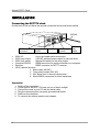
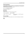
Connecting the DCF77N clock
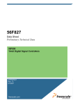
On the back of the unit there are several connectors and a push button switch:
230VAC
HD15, special
functions
•
•
•
•
•
•
Computer
RS232
Receiver
230V relay
switch
230V AC:
Use a grounded mains connection!
230V relay output:
230VAC switched mains output for use with timer
230V relay switch:
Manual ON switch for the relay output
Computer RS232:
DB9M connector for serial connection to a computer
Receiver:
DB9F connector for DCF77 receiver
HD15, special functions :
1. Alarm relay (NO,NC)
2. Timer relay contact (NO, NC)
3. 24V Slave clock 1 second minute pulse
4. Extra RS232 connection for future expansion
Connection
1. Switch off the computer
2. Find a spot for the DCF77N main unit out of direct sunlight
3. Connect the clock to your PC with the serial cable
4. Plug the mains plug into a properly grounded wall outlet
5. Switch on the computer.
6. To connect the receiver see the next chapter.
2
230V
relay
output
Atomic DCF77 Clock
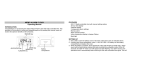
Receiver installation
The DCF receiver is housed in a small box with a 5 meter cable attached. If 5 meter is
not long enough the cable can be extended up to max. 50 meters. In the chapter
"Extending the receiver cable" is shown how to do this.
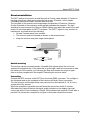
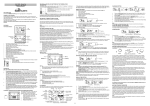
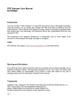
The long side of the receiver must be pointed in the direction of Frankfurt, Germany.
On the underside of the receiver a small red light indicates the reception. The light
should be on each second for 100ms or 200ms. Before you attach the receiver to a wall
check if it is the best place for DCF77 reception. The DCF77 signal is very sensitive to
interference, so please check the following:
• At least 2 meters away from monitors.
• The receiver must be mounted as shown on the picture below.
• Keep the receiver away from large metal objects
Frankfurt
Outside mounting
The receiver can be mounted outside. If possible find a place where the unit is not
exposed to sunlight all day. If the cable has to go through a wall we recommend to take
the cable out of the receiver, put it through the hole and connect the receiver again.
How to do this is explained in the chapter "Extending the receiver cable" .
Connecting
Connect the DCF-receiver to the DC77N on the lower DB9F connector. The red light in
the frontpanel and on the underside of the receiver will blink if there is reception.
Turn the receiver until the light blinks every second for a short period (0,1 or 0,2 sec.),
except at the 59th second.
When the reception is good the clock will show the correct time within 5 minutes.
After each fully received minute the signal quality indicator on the display (top-right
corner) will show 5 lines increasing in length. If the indicator has less than 5 lines after a
period of 10 minutes the reception is not good, in this case relocate the receiver.
3
Atomic DCF77 Clock
Utility software
There are several programs on the CD to set the clock and to set the time in your PC.
The programs are located in different folders for different operating systems.
Each folder contains the software and some documentation if needed.
WIN9598:
Programs for Windows 95, 98, Millennium and XP
WIN31311:
Programs for Windows 3.1 and 3.11
WINNT:
Programs for Windows NT and 2000
DOS:
Programs for MS-DOS and to synchronize to a Novell file server
NOVELL:
File server Network Loadable Module software.
LINUX:
Program for linux
SUN:
Program for Sun solaris
For MSWindows (95,98, Millennium, NT and 2000) a simple program can be used to set
all settings of the DCF77N clock. This DCFSetup program will be explained in the next
chapter.
To set the clock in other operating systems you have to use a terminal program. For
more information see chapter "Terminal commands".
4
Atomic DCF77 Clock
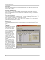
DCFSETUP PROGRAM
DCFSetup (95, 98, NT, Millennium and 2000)
With this program you can program all settings (including the timer) of the clock.
Copy the DCFSetup program from CD to a DCF folder on your local harddisk.
It is possible to run the program from CD but the COM-port choice will not be saved in
this case. First quit all running DCF programs, only one program can use the serial port.
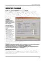
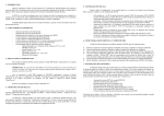
When you start the program the following screen appears:
Settings tab
Language:
This program has 5
language choices. For
English click the button
left to "English".
230V relay mode:
The 230V output can
function in 4 different
modes.
• Off, the 230V output
is switched off.
• On, the 230V output
is switched on.
• Alarm, normally the
output will be Off,
when the time is not
synchronised the
output will be On.
• Timer, it is possible to
set 8 switch moments
for each day. See
"Timer tab" for more information on the timer.
Serial port:
Choose the correct port (where the clock is connected to). Your choice will be saved to
harddisk for the next time. The unavailable ports are shown grey.
If a wrong port is chosen an error message will appear, in this case check the serial
cable and select the port where it is connected to.
Serial port not available:
If the serial port where the clock is connected to is not shown, quit the DCFSetup
program and quit any running DCF utility programs. Only one program can use the
serial port at the same time!
5
Atomic DCF77 Clock
UTC offset:
This setting determines the time zone. The value is the time difference between local
time and UTC (=GMT).
Automatic daylight saving
If this setting is "1" (On) the time will be set forward on the last Sunday morning in
March from 03:00 to 04:00 and set back on the last Sunday morning in October from
03:00 to 02:00.
Time not valid timeout
This is the time before the 'not synchronised' message will appear. Default value is 72
hours, this gives a maximum of 0.5 seconds time error.
When there is no mains supply, there is also no DCF reception. For an exact time it is
important to always leave the clock on.
Send/receive
The lower progress bar shows the progress of data communication between PC and
clock.
Timer tab
On this tab you can set 8
switch times per day for
the mains relay output.
Click on the square next
to one of the 8 times.
With On/Off you can
select the output state.
To edit the time use the
leftmost window 'Edit
selected time' and click
on the up/down arrows to
change.
When all switch times
have been set you can
press 'Send settings to
clock'. The progress bar
will now fill up to 100%.
Now all settings are valid.
The clock will remember
these settings, so unless
you want to change
something you can leave the program now.
6
Atomic DCF77 Clock
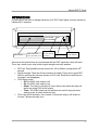
OPERATION
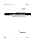
On the front of the clock a red light inside the O of 'DCF clock' lights up every second to
indicate DCF reception.
DCF CLOCK
DCF LED
03:53:56 (Ti)
20-02-2002
Relay mode:
230V relay
Off,on,Alarm
hour:min:sec.
on/off indicator
Signal
strength
Day-month-year or Timer
As soon as the internal time is synchronised with the DCF signal the clock will show
Time, day, month, year, relay mode, signal strength and relay position.
•
•
•
•
DCF led: This light blinks every second for 100 or 200ms, except at the 59th
second.
Signal strength: There are 5 bar increasing in length. Every time a good DCF
frame is received an extra bar shows, up to 5 max. Each time a bad frame is
received 1 bar disappears.
230V Relay mode:
o Off, the 230V relay output is off.
o On, the 230V relay output is on.
o Alarm, The relay is normally off, when there is an alarm the relay will
switch on giving 230V at the output
o Timer, The 230V output can be switched on and off using the timer
settings (max. 8 switch times per day).
230V relay on/off indicator, if an inverse 'o' shows the relay is off, when an
inverse 'I' shows the relay is on.
7
Atomic DCF77 Clock
Connections
230V Relay output
On the back of the clock is the
230V relay output. This output
can be programmed by the
timer. Maximum switch power
is 1000W and is fused with a 6,3A fuse.
HD15 special functions
1: Slaveclock +
2: Serial2 out
3: Serial2 in
4: NC alarm contact
5: NO alarm contact
230V relay
activate
HD15, special
functions
6: Slaveclock Common
7: NC extra contact (timer)
8: CO extra contact (timer)
9: NO extra contact (timer)
10: 0V, gnd
230V
relay
output
11: Slaveclock 12: 0V, gnd
13:+24V output (1A fuse)
14:+5V output (1A fuse)
15:CO alarm contact
Extra timer relay contact
Together with the mains relay output relay a separate relay contact switches at the
same time.
HD15, Pin 7:
HD15, Pin 8:
HD15, Pin 9:
Common (CO)
Normally closed (NO)
Normally open (NC)
Alarm contact
NO + CO: This contact is normally open or
closed and will switch when power is off or the
time is not synchronised. .
HD15, Pin 4:
HD15, Pin 15:
HD15, Pin 5:
Common (CO)
Normally closed (NO)
Normally open (NC)
24V slave clock output
The slave clock output gives every minute a 24V
signal with changing polarity and a duration of 1
second. Max. current is 500mA.
HD15, Pin 1:
HD15, Pin 6:
HD15, Pin 11:
8
Slaveclock +
Common
Slaveclock -
NC
5
NO
Common
4 3 2 1
10 9 8 7 6
15 14 13 12 11
NC NO Common
5
4 3 2 1
10 9 8 7 6
15 14 13 12 11
Slave+ Common Slave5
4 3 2 1
10 9 8 7 6
15 14 13 12 11
Atomic DCF77 Clock
+5V and +24V outputs
Both outputs can be used to power external devices with a maximum current of 500mA.
HD15, pin 12: 0V, massa
HD15, pin 13: +24V output (1A fuse)
HD15, pin 14: +5V output(1A fuse)
Serial2
For future expansion.
HD15, pin 2: RS232 output
HD15, pin 3: RS232 output
230V Relay activation switch
Next to the mains output is a small button located. This switch can be used to switch the
mains power ON, when it is OFF. This can be used in those cases where a computer is
switched on and off automatically by the clock and you want to switch the computer on
manually.
RS232 Computer connection (DB9M)
The top 9 pole connector is used to connect the computer
to the DCF77N clock.
gnd
RXD TXD
5
DB9M, pin 2: TXD
DB9M, pin 3: RXD
DB9M, pin 5: GND
4
9
2
3
8
7
1
6
RS232 cable ( shielded)
Female 9 pole (DB9F)
Pin 1
Pin 2
Pin 3
Pin 4
Pin 5
Pin 6
Pin 7
Pin 8
Pin 9
Female 9 pole (DB9F)
Pin 1
Pin 2
Pin 3
Pin 4
Pin 5
Pin 6
Pin 7
Pin 8
Pin 9
Receiver connector (DB9F)
See chapter 'Connecting the DCF receiver'.
9
Atomic DCF77 Clock
Terminal commands
All clock settings can be programmed by using a terminal program.
Serial settings:
Set the terminal program to the correct serial port and the following serial setting.
Baudrate:19200, Databits:8, Stopbits:1, Parity: Even
All clock commands start with a '$' sign and ends with a Carriage return (CR).
$N=X The 'N' is the command number and the 'X' is the value:
Setting 1 = Language
example: $1=2
Possible values:
{= English}
0=
1=
2=
3=
4=
Dutch
German
English
French
Polish
Setting 2 = UTC difference
Possible values: -12 ... 12
This is the time difference between your local time and Universal Time
Coördinated (UTC or GMT).
example: $2=1 {+1 hour difference to UTC}
Setting 3 = Automatic daylight saving Possible values: 0 or 1 {off or on}
Daylight saving On/Off: When "ON" the time will be set back 1 hour at 03:00 the
last Sunday morning in March and 1 hour forward at 02:00 the last Sunday
morning in October.
example: $3=1 { Automatic daylight saving is on}
Setting 4 = Time valid period
Possible values: 1 ... 99
This specifies the length of time before the clock will report that it has not
received a correct DCF signal. Default is 72 hours which results in less than max.
0.5 seconds time error.
example: $4=72 { Time valid period = 72 hours}
Setting 5 = Relay mode,
0 = Off
1 = On
2 = On when not synchronised
3 = Timer
This setting determines the way the 230 output is used. Off, On or as a warning for
an unsynchronised time
example: $5=3 { The mains relay output will switch on/off at times defined in the
timer settings, see next chapter}
10
Possible values:
Atomic DCF77 Clock
Timer programming
When the relay mode is set to Timer ($5=3), you can program the switch times with the
commands $21 up to $27. This timer uses weekday programming, so command $21 is
for Monday, $22 is for Tuesday, etc.
There is a maximum of 8 switch times per day.
$<21..27> =N,HH,MM,SS,<ON/OFF>
N is switch time number (0..7)
HH is the hour
MM is minutes
SS is seconds
ON/OFF to indicate on or off for the mains relay output.
To delete a switch time:
example:
$<21..27>=N,DEL
$22=1,11,10,00,ON
Every Tuesday at 11:10:00 The output is
switched On
Factory settings
To reset the clock to its factory state you have to enter the following two commands:
$99=
$100=
11
Atomic DCF77 Clock
Programming information
The next chapter describes the commands you can use to get the time from the clock to
your computer. This information can be used to write your own driver for operating
systems that are not supported by Elproma.
Serial settings (asynchronic):
Baudrate:19200, Databits:8, Stopbits:1, Parity: Even
Time request
Request send to the time.
1. 75h (= 117 dec) Time request. The answer from the DCF PC Clock is send to
the computer at the half of the second (can be the same second!).
2. 78h (= 120 dec) - Time request. The answer from the DCF PC Clock is send to
the computer at the beginning of the next second.
Automatical time transmission:
The following byte can be send to the clock: 01xxxxxx (Bin)
xxxxxx is a binairy number from 0 to 63 which is the time interval in minutes. Every time
this interval has passed the clock will send the time on the first second of the minute.
example:
40h (=64 dec) stop automatic transmission
41h (=65 dec) every minute the time will be sent
Clock time format:
The clock sends the following 10 bytes:
- START_BYTE
BAh - when the request was 75h
- OR
BBh - when the request was 78h
- HOURS
Binary
- MINUTES
Binary
- SECONDS
Binary
- YEAR
Binary
- MONTH
Binary
- DAY_OF_MONTH Binary
- WEEK_DAY
Binary,( Mon=1, Tue=2, ...,Sun=7)
- CHECK_SUM
checksum (sum modulo 256) of fields 2-8
After the calculation the result is logical ANDed with 7Fh and the result placed in this
field.
- STOP_BYTE_VAL C5h - when the time is valid
OR
- STOP_BYTE_INV D2h - when the time is invalid
12
Atomic DCF77 Clock
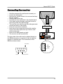
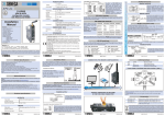
Connecting the receiver
o Hold the antenna with metal bracket towards you.
o Loosen the cable gland.
o Remove the 4 small screws in the corners that keep
the box together.
o Carefully take off the top.
o Unscrew the three connection in the terminal block.
o If the cable is going through a wall then first drill a
hole and put the new cable through.
o Then put the new cable through the cable gland and
connect as shown in the picture.
o Check the connections carefully!
o Now first put the screws back and put the sealing
rings on top. Now replace the top of the box and
close the box tight.
o Now turn the cable gland very tight.
o The receiver can be mounted now.
Unscrew
The other side of the cable can be soldered directly to
the DB9M connector or connected to the old cable by
means of a terminal block. The connections of the
DB9M are shown below.
0 (shield)
5
4
9
+ (red)
2
3
8
7
1
+
red
0 shield
white
uit
6
Output (white)
13
Atomic DCF77 Clock
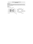
Trouble shooting
Serial port not available in DCFSetup:
If the serial port where the clock is connected to is not shown, quit the DCFSetup
program and quit any running DCF utility programs (e.g. DCFWIN).
Only one program can use the serial port at the same time!
LED does not blink
1. DCF-receiver is placed in the wrong position or wrong location. Try to turn the
receiver until the led starts to flash.
2. Remove the receiver from the wall and try to walk around for a better location.
3. DCF-Receiver is not connected to the lower DB9 connector.
DCFClock always starts with the wrong time
Inside the clock a small lithium battery supplies the internal backup clock. The battery
has an expected life of more than 10 years in normal use, but when the clock is often
switched off, the battery will be empty sooner. The minimal expected life is 5 years.
When the battery is empty, the internal clock does not run anymore. This can be
checked by switching the unit off at zero seconds, then after ten seconds back on and
check the display. If the clock starts where you switched it off, the battery is empty. In
this case please call our service department for a replacement battery.
14
Atomic DCF77 Clock
Specifications
DCF77N
Ambient temp.
Mains supply
Dimensions
Weight
230V output
Relay outputs
Accuracy
10°C to max. 40°C
230VAC 24 Watt max, 250mA fuse
200 x 190 x 80 mm.
800 g.
230VAC 1000W max, 6,3A fuse
Normally open or closed contacts, 1A fuse
When synchronised: -10ms up to +40ms max. deviation
unsynchronised: +/-7,2 ms max. per hour
DCF-Receiver
Ambient temp.
Supply
Dimensions
Mounting
•
•
•
•
-30° to max. +50° Celsius
8VDC to 12VDC
85 x 45 x 22 mm
wall bracket
Never place the main DCF77N unit in direct sunlight.
The computer and clock should be grounded properly.
Don't use any solvents to clean the unit.
Don't open the main DCF77N unit unless you are a certified repair engineer
15