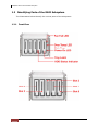
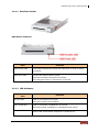
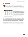
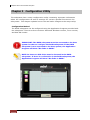
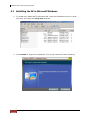
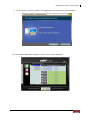
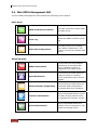
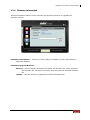
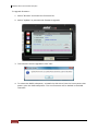
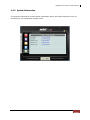
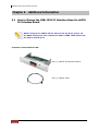
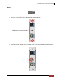
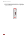
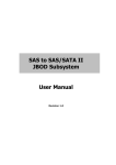
1
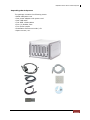
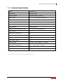
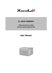
Mini-EPICa USB/IEEE 1394-to-SATA II RAID Subsystem User Manual Revision 1.0 USB/IEEE 1394-to-SATA II RAID Subsystem Contents Preface ................................................................................................................................3 Before You Begin .............................................................................................................4 Chapter 1 Introduction ...............................................................................................6 1.1 Technical Specification..........................................................................................................................................7 1.2 Identifying Parts of the RAID Subsystem......................................................................................................8 1.2.1 1.2.1.1 Disk Drive Carrier ..................................................................................................................................9 1.2.1.2 LED Indicators .........................................................................................................................................9 1.2.2 1.3 Front View .........................................................................................................................................................8 Rear View........................................................................................................................................................ 10 RAID Concepts ...................................................................................................................................................... 11 Chapter 2 2.1 Getting Started........................................................................................14 Installing Hard Drives ......................................................................................................................................... 14 2.1.1 2.2 Installing the Rubber Feet ....................................................................................................................... 16 Preparing the Subsystem and Powering On ............................................................................................ 17 Chapter 3 3.1 Configuration Utility ..............................................................................18 Installing the AP in Microsoft Windows..................................................................................................... 20 3.2 Starting the AP in Linux..................................................................................................................................... 22 3.3 Starting the AP in Mac OS ................................................................................................................................. 23 3.4 Mini-EPICa Management GUI ......................................................................................................................... 24 3.4.1 Other Buttons of the mini-EPICa Management GUI .................................................................... 25 Chapter 4 4.1 RAID Management................................................................................27 Basic Mode ............................................................................................................................................................. 27 4.1.1 RAID and Disk Information ..................................................................................................................... 27 4.1.2 Event Log........................................................................................................................................................ 30 4.1.3 Basic Raid Configuration.......................................................................................................................... 31 4.2 Advanced Mode ................................................................................................................................................... 35 4.2.1 SMART Information .................................................................................................................................... 35 4.2.2 Email Notification........................................................................................................................................ 36 4.2.3 Advanced Raid Configuration ................................................................................................................ 37 4.2.4 Firmware Information ................................................................................................................................ 41 4.2.5 System Information .................................................................................................................................... 43 Chapter 5 5.1 Additional Information.........................................................................44 How to Change the USB/1394 IO Interface Board to eSATA IO Interface Board .................... 44 2 User Manual USB/IEEE 1394-to-SATA II RAID Subsystem Preface About this manual his manual provides information regarding the quick installation and hardware features of the mini-EPICa USB/IEEE 1394-to-SATA II RAID subsystem. This document also describes how to use the storage management software. Information contained in the manual has been reviewed for accuracy, but not for product warranty because of the various environment/OS/settings. Information and specifications will be changed without further notice. This manual uses section numbering for every topic being discussed for easy and convenient way of finding information in accordance with the user’s needs. The following icons are being used for some details and information to be considered in going through with this manual: NOTES: These are notes that contain useful information and tips that the user must give attention to in going through with the subsystem operation. IMPORTANT! These are the important information that the user must remember. WARNING! These are the warnings that the user must follow to avoid unnecessary errors and bodily injury during hardware and software operation of the subsystem. CAUTION: These are the cautions that user must be aware of to prevent damage to the equipment and its components. Copyright No part of this publication may be reproduced, stored in a retrieval system, or transmitted in any form or by any means, electronic, mechanical, photocopying, recording or otherwise, without the prior written consent. Trademarks All products and trade names used in this document are trademarks or registered trademarks of their respective owners. Changes The material in this document is for information only and is subject to change without notice. User Manual 3 USB/IEEE 1394-to-SATA II RAID Subsystem Before You Begin efore going through with this manual, you should read and focus on the following safety guidelines. Notes about the subsystem’s controller configuration and the product packaging and delivery are also included. To provide reasonable protection against any harm on the part of the user and to obtain maximum performance, user is advised to be aware of the following safety guidelines particularly in handling hardware components: Upon receiving of the product: Place the product in its proper location. It should be handled with care to avoid dropping that may cause damage to the product. Always use the correct lifting procedures. Upon installing of the product: Ambient temperature is very important for the installation site. It must not exceed 30◦C. Due to seasonal climate changes; regulate the installation site temperature making it not to exceed the allowed ambient temperature. Before plugging-in any power cords, cables and connectors, make sure that the power switches are turned off. Disconnect first any power connection if the power supply module is being removed from the enclosure. Outlets must be accessible to the equipment. All external connections should be made using shielded cables and as much as possible should not be performed by bare hand. Using anti-static hand gloves is recommended. In installing each component, secure all the mounting screws and locks. Make sure that all screws are fully tightened. Follow correctly all the listed procedures in this manual for reliable performance. Controller Configurations This RAID subsystem supports single controller configuration. Packaging, Shipment and Delivery Before removing the subsystem from the shipping carton, you should visually inspect the physical condition of the shipping carton. Unpack and verify that the contents of the shipping carton are complete and in good condition. Exterior damage to the shipping carton may indicate that the contents of the carton are damaged. If any damage is found, do not remove the components; contact the dealer where you purchased the subsystem for further instructions. 4 User Manual USB/IEEE 1394-to-SATA II RAID Subsystem Unpacking the Subsystem The package contains the following items: • RAID subsystem unit • One power adapter with power cord • One USB cable • Two IEEE 1394b cables • Four (4) Rubber Feet • Two screw handle • Installation Reference Guide / CD • Spare screws, etc. User Manual 5 USB/IEEE 1394-to-SATA II RAID Subsystem Chapter 1 Introduction The RAID Subsystem Unsurpassed Value - Most cost-effective SATA II RAID subsystem. - Compact Desktop size with stylish design. Application Flexibility - Extends useful life by adapting to future IT/SOHO requirements. Easy Installation & Maintenance - Provide a fast and easy way to install and manage the storage. Low Power Consumption - Cable-less backplane with integrated RAID processor. No more unnecessary components inside. Features - USB 2.0/IEEE 1394b host interface - Supports RAID over 2TB - Supports hot spare and automatic hot rebuild - Local event notification - Easy management via In-Band data bus - Transparent data protection for all popular operating systems RAID Management - Real time drive activity and status indicators - Graphical User Interface (GUI) management utility 6 User Manual USB/IEEE 1394-to-SATA II RAID Subsystem 1.1 Technical Specification Model EP-m501-CA Form Factor Compact Tower RAID Processor Integrated Micro-processor RAID Levels 0, 1, 3, 5, 10, LARGE and CLONE Host Interface USB 2.0 or IEEE 1394b Number of Host Channel 1 Data Transfer Rate Up to 480Mbit/s (USB 2.0)/800Mbit/s (1394b) Disk Interface SATAII (3Gb/s) Number of Hot-swap Disk Trays Five (5) 2.5-inch SFF Disk trays Cooling Fans 1 Failed Drive Indicators Yes Failed Drive Auto Rebuild Yes Environment Monitor Yes Auto Spare Support Yes Power Supply 60W Ext. Power Adapter (full range) Environmental Relative Humidity: Operating Temperature: 10% ~ 85% Non-condensing 10°C ~ 40°C (50°F ~ 104°F) Dimension 147(H) x 116(W) x 190(D)mm Weight 3.3Kg (without disks) Specification is subject to change without notice. User Manual 7 USB/IEEE 1394-to-SATA II RAID Subsystem 1.2 Identifying Parts of the RAID Subsystem The illustrations below identify the various parts of the subsystem. 1.2.1 Front View 8 User Manual USB/IEEE 1394-to-SATA II RAID Subsystem 1.2.1.1 Disk Drive Carrier HDD Status Indicator Function Part HDD Access LED This LED will blink blue when the hard drive is busy or being accessed. HDD Fault LED Green LED means HDD is good. Red LED indicates hard drive has failed. No LED light means no hard drive in the slot. 1.2.1.2 LED Indicators Part Function Fan Fail LED LED is off means Fan is good. Red LED means Fan has failed. Over Temp LED LED is off means Temperature is normal. Red LED means Temperature exceeded normal range. Power On LED White LED means RAID subsystem is powered on. User Manual 9 USB/IEEE 1394-to-SATA II RAID Subsystem 1.2.2 Rear View USB 2.0 Port The subsystem has one USB port for connecting to Host/Server. IEEE 1394b Port The subsystem has one IEEE 1394b port for connecting to Host/Server. Fan The fan provides proper ventilation for the RAID subsystem. Power On/Off Switch Use the Power On/Off Switch to turn on or off the RAID subsystem. Power Input Socket Use the Power Input Socket for connecting the power adapter. NOTE: USB and IEEE 1394 ports use same channel. Only one host connection will work at a time. You cannot use both USB and IEEE 1394 ports at the same time. 10 User Manual USB/IEEE 1394-to-SATA II RAID Subsystem 1.3 RAID Concepts he basic idea of RAID (Redundant Array of Independent Disks) is to combine multiple inexpensive disk drives into an array of disk drives to obtain performance, capacity and reliability that exceeds that of a single large drive. The array of drives appears to the host computer as a single logical drive. Five types of array architectures, RAID 1 through RAID 5, were originally defined; each provides disk fault-tolerance with different compromises in features and performance. In addition to these five redundant array architectures, it has become popular to refer to a non-redundant array of disk drives as a RAID 0 arrays. Disk Striping Fundamental to RAID technology is striping. This is a method of combining multiple drives into one logical storage unit. Striping partitions the storage space of each drive into stripes, which can be as small as one sector (512 bytes) or as large as several megabytes. These stripes are then interleaved in a rotating sequence, so that the combined space is composed alternately of stripes from each drive. The specific type of operating environment determines whether large or small stripes should be used. Most operating systems today support concurrent disk I/O operations across multiple drives. However, in order to maximize throughput for the disk subsystem, the I/O load must be balanced across all the drives so that each drive can be kept busy as much as possible. In a multiple drive system without striping, the disk I/O load is never perfectly balanced. Some drives will contain data files that are frequently accessed and some drives will rarely be accessed. By striping the drives in the array with stripes large enough so that each record falls entirely within one stripe, most records can be evenly distributed across all drives. This keeps all drives in the array busy during heavy load situations. This situation allows all drives to work concurrently on different I/O operations, and thus maximize the number of simultaneous I/O operations that can be performed by the array. User Manual 11 USB/IEEE 1394-to-SATA II RAID Subsystem Definition of RAID Levels RAID 0 is typically defined as a group of striped disk drives without parity or data redundancy. RAID 0 arrays can be configured with large stripes for multi-user environments or small stripes for single-user systems that access long sequential records. RAID 0 arrays deliver the best data storage efficiency and performance of any array type. The disadvantage is that if one drive in a RAID 0 array fails, the entire array fails. RAID 1, also known as disk mirroring, is simply a pair of disk drives that store duplicate data but appear to the computer as a single drive. Although striping is not used within a single mirrored drive pair, multiple RAID 1 arrays can be striped together to create a single large array consisting of pairs of mirrored drives. All writes must go to both drives of a mirrored pair so that the information on the drives is kept identical. However, each individual drive can perform simultaneous, independent read operations. Mirroring thus doubles the read performance of a single non-mirrored drive and while the write performance is unchanged. RAID 1 delivers the best performance of any redundant array type. In addition, there is less performance degradation during drive failure than in RAID 5 arrays. Dual-level RAID achieves a balance between the increased data availability inherent in RAID 1 and the increased read performance inherent in disk striping (RAID 0). These arrays are sometimes referred to as RAID 10. RAID 3 sector-stripes data across groups of drives, but one drive in the group is dedicated to storing parity information. RAID 3 relies on the embedded ECC in each sector for error detection. In the case of drive failure, data recovery is accomplished by calculating the exclusive OR (XOR) of the information recorded on the remaining drives. Records typically span all drives, which optimizes the disk transfer rate. Because each I/O request accesses every drive in the array, RAID 3 arrays can satisfy only one I/O request at a time. RAID 3 delivers the best performance for single-user, single-tasking environments 12 User Manual USB/IEEE 1394-to-SATA II RAID Subsystem with long records. Synchronized-spindle drives are required for RAID 3 arrays in order to avoid performance degradation with short records. RAID 5 arrays with small stripes can yield similar performance to RAID 3 arrays. Under RAID 5 parity information is distributed across all the drives. Since there is no dedicated parity drive, all drives contain data and read operations can be overlapped on every drive in the array. Write operations will typically access one data drive and one parity drive. However, because different records store their parity on different drives, write operations can usually be overlapped. RAID Management The subsystem can implement several different levels of RAID technology. RAID levels supported by the subsystem are shown below. RAID Level Description Min. # of Drives 0 Block striping is provided and yields higher performance than with individual drives. There is no redundancy. 2 1 Drives are paired and mirrored. All data is 100% duplicated on an equivalent drive. Fully redundant. 2 LARGE Large is similar to RAID 0 in that it combines the capacity of all member drives. The data is written linearly starting with the first disk drive. When first disk drive becomes full, the next disk drive is used. Large can have 2 or more disk drives. There is no data redundancy. 2 CLONE Clone provides multiple copies of data in a disk drive. Clone can have 2 or more disk drives. 2 3 Data is striped across several physical drives. Parity protection is used for data redundancy. 3 5 Data is striped across several physical drives. Parity protection is used for data redundancy. 3 Combination of RAID levels 1 and 0. This level provides striping and redundancy through mirroring. 4 10 User Manual 13 USB/IEEE 1394-to-SATA II RAID Subsystem Chapter 2 Getting Started This section describes the physical locations of the hard drives supported by the subsystem and give instructions on installing a hard drive. The subsystem supports hot-swapping allowing you to install or replace a hard drive while the subsystem is running. This also discusses on how to power-on the subsystem in preparation for operation. 2.1 Installing Hard Drives a. Push the tray latch to release a disk tray. b. Then pull out the (empty) disk tray. 14 User Manual USB/IEEE 1394-to-SATA II RAID Subsystem c. Place the hard drive in the disk tray. Make sure the holes of the disk tray align with the holes of the hard drive. d. Install the mounting screws on the bottom part to secure the drive in the disk tray. e. Slide the tray into a slot until it reaches a full stop. f. Press the lever in until you hear the latch click into place. User Manual 15 USB/IEEE 1394-to-SATA II RAID Subsystem 2.1.1 Installing the Rubber Feet Four (4) rubber feet can be attached to the base of the unit to provide stable stand. The following are the steps in installing the rubber feet: 1. Prepare the four (4) rubber feet. 2. Remove the rubber feet by pulling it outward. 3. Attach the rubber feet on the base of the unit. The rubber feet can also be pasted on the unit anywhere the user prefers, but must be evenly spaced so that the unit will stand firm and stable. 16 User Manual USB/IEEE 1394-to-SATA II RAID Subsystem 2.2 Preparing the Subsystem and Powering On Here are the steps to prepare the RAID subsystem for use. 1. Connect the USB cable or IEEE 1394 cable from RAID subsystem to the USB port or IEEE 1394 port on Host/Server. NOTE: Only one host connection will work at a time. You cannot use both USB and IEEE 1394 ports at the same time. 2. Connect the power adapter to the power input socket. Plug the other end of power cord to the power source. 3. Turn on the Power On/Off Switch. User Manual 17 USB/IEEE 1394-to-SATA II RAID Subsystem Chapter 3 Configuration Utility The subsystem has a setup configuration utility containing important information about the configuration as well as settings for various optional functions in the subsystem. This chapter explains how to use and make changes to the setup utility. Configuration Method The RAID subsystem can be configured using the Application Program provided with the subsystem. There are three versions: Microsoft Windows version, Linux version, and Mac OS version. IMPORTANT: The RAID subsystem must be connected to the Host system in order to configure the RAID subsystem. If the RAID subsystem is not connected to the Host system, the Application Program will show “No disks or RAID!” NOTE: At least one disk drive must be inserted in the RAID subsystem. If there is no disk drive in the RAID subsystem, the Application Program will show “No disks or RAID!” 18 User Manual USB/IEEE 1394-to-SATA II RAID Subsystem IMPORTANT: When hard disks are inserted in the disk slots, the first inserted hard disk is assigned “Port 0”. Port 0 is the (in-band) channel that will be used by mini-EPICa AP to manage the RAID controller. Other hard disks will be assigned Port1, Port 2, etc. If the first hard disk assigned as Port 0 is removed, the AP cannot access and manage the RAID controller. When a RAID Set is already created, the first hard disk that was inserted and assigned Port 0 (whether or not it is part of the RAID Set) can then be removed and the AP can still manage the RAID controller. User Manual 19 USB/IEEE 1394-to-SATA II RAID Subsystem 3.1 Installing the AP in Microsoft Windows 1. To install mini-EPICa AP for Windows OS, copy the installation files to a local directory and open the setup.exe program. 2. Click Install to begin the installation. The setup wizard will start installing. 20 User Manual USB/IEEE 1394-to-SATA II RAID Subsystem 3. Click Finish to exit the wizard. The application will be launched immediately. The mini-EPICa Application Program main screen will be displayed. User Manual 21 USB/IEEE 1394-to-SATA II RAID Subsystem 3.2 Starting the AP in Linux To configure the RAID subsystem when connected to Linux system, go to the directory where the Application Program is saved and open the Application Program. This example is from Fedora Core 9. Another way is to open terminal window, then at the command prompt type “./miniEPICaRaidSetup”. After running the Application Program, the mini-EPICa main screen will be displayed. 22 User Manual USB/IEEE 1394-to-SATA II RAID Subsystem 3.3 Starting the AP in Mac OS To configure the RAID subsystem when connected to Mac OS X Server, go to the directory where the Application Program is saved and open the Application Program. This example is from Mac OS X Server version 10.5.4. After running the Application Program, the mini-EPICa main screen will be displayed. User Manual 23 USB/IEEE 1394-to-SATA II RAID Subsystem 3.4 Mini-EPICa Management GUI The mini-EPICa management GUI contains the following menu options: Basic Mode: RAID and Disk Information Provides information about RAID and disk drives. Event Log Shows the RAID controller event log. Basic Raid Configuration Provides function for creating basic RAID configuration. This function will use all available disk drives. SMART Information This function will show SMART information of the SATA disk drives if SMART function is supported by the disk drives. Email Notification This function provides option to configure email for sending event notifications when events happen. Advanced Raid Configuration This function provides option to customize RAID configuration and select disk drive members. Firmware Information Shows information about current firmware and provides function to upgrade the firmware version. System Information Shows information about the system such as temperature, fan speed and voltage levels. Advanced Mode: 24 User Manual USB/IEEE 1394-to-SATA II RAID Subsystem 3.4.1 Other Buttons of the mini-EPICa Management GUI Minimize Window button – Used to minimize the mini-EPICa GUI into taskbar. Close Windows button – Used to close the mini-EPICa GUI. Note that the AP is still running in the background. To exit the AP, right-click the mini-EPICa icon in the task bar then select Quit from the pop-up menu. User Manual 25 USB/IEEE 1394-to-SATA II RAID Subsystem About button – Used to display the current mini-EPICa AP version. Turn Off the Buzzer – Use this to silence the alarm buzzer. 26 User Manual USB/IEEE 1394-to-SATA II RAID Subsystem Chapter 4 RAID Management This chapter provides details about configurations and options available in the RAID subsystem. There are two modes of operation: Basic Mode and Advanced Mode. 4.1 Basic Mode Under Basic Mode, there are three menu options that can be selected: RAID and Disk Information, Event Log, and Basic Raid Configuration. 4.1.1 RAID and Disk Information RAID and Disk Information provides information about RAID and disk drives. RAID and Disk Information: No existing RAID configuration User Manual 27 USB/IEEE 1394-to-SATA II RAID Subsystem Disk Information: Disk drive is “Unused” or not a RAID member. RAID Information: Disk Drives are RAID 5 member. RAID Information: RAID Level – Shows the RAID Level of the RAID Status – Shows the current status of the RAID. Status can be: Normal – No failed disk drive. Degrade – One or more disk drives failed in a RAID Level with data redundancy. The data is still accessible. Broken – One or more disk drives failed in a RAID Level. The number of allowable failed disk drives in the RAID Level has been exceeded and data is not accessible. Rebuilding (%) – The RAID is in rebuilding state. The completed rebuilding percentage is shown. Capacity – Shows the capacity of the RAID Plugged Member(s) – Shows the disk drive slots which are member of the RAID 28 User Manual USB/IEEE 1394-to-SATA II RAID Subsystem Disk Information: Disk drive is a RAID member. Disk Information: Model Name – Shows the disk drive model Serial Number – Shows the disk drive serial number Firmware Version – Shows the disk drive’s firmware version Capacity – Shows the capacity of the disk drive Unused Capacity – Shows the amount of unused capacity in the disk drive User Manual 29 USB/IEEE 1394-to-SATA II RAID Subsystem 4.1.2 Event Log The RAID controller event log can be viewed from this menu. It will show the Number of Events, the Issued Module, Date, Type, and Message. Event Log Buttons: Save To File – This option allows the event logs to be saved as a log text file (.log). Enter the filename you want for the log file and click “Save”. Clear – Selecting this option will clear the event log. When the dialog box shown below is displayed, select “Yes” to delete all event logs. 30 User Manual USB/IEEE 1394-to-SATA II RAID Subsystem 4.1.3 Basic Raid Configuration This menu provides function for creating basic RAID configuration. This function will use all available disk drives in the RAID subsystem. Basic Raid Configuration Options: Configure RAID – Select the RAID Level from the list of options. The RAID Levels that can be selected for the number of available disk drives are enabled. When there is an existing RAID, the “DELETE ALL RAID(s)” option is enabled. Support Password – This option provides RAID security. When this option is enabled and a password is entered in the corresponding box, deleting the RAID will require the password to be entered. Using a wrong password will not allow the RAID to be deleted. The password can be up to 8 characters. Basic Raid Configuration Buttons: Apply – Save the configuration and create the RAID. Cancel – Undo the current operation. NOTE: The RAID subsystem supports up to two RAIDs. User Manual 31 USB/IEEE 1394-to-SATA II RAID Subsystem To create a RAID using Basic Raid Configuration: 1. In the Configure RAID option, select the RAID Level you want for the RAID. Click “Apply” to save the RAID configuration. 2. When a dialog box is displayed, select “Yes” to confirm creating RAID. 3. A progress bar will be shown. 32 User Manual USB/IEEE 1394-to-SATA II RAID Subsystem 4. An information message will be displayed. Click “OK”. 5. The RAID is created successfully. The RAID will be available to the Host/Server immediately and a new disk device will be detected. User Manual 33 USB/IEEE 1394-to-SATA II RAID Subsystem 6. Check the new disk drive in your Host/Server. Example: Connection via USB In Microsoft Windows under Device Manager, the new disk drive (Proware H/W RAID5 USB Device) is displayed. Example: Connection via IEEE 1394 In Microsoft Windows under Device Manager, the new disk drive (Proware H/W RAID IEEE 1394 SBP2 Device) is displayed. 34 User Manual USB/IEEE 1394-to-SATA II RAID Subsystem 4.2 Advanced Mode 4.2.1 SMART Information This function will show SMART information of the disk drives if SMART function is supported by the disk drives. NOTE: The SMART information will be shown only if a RAID is already created. Click on a disk drive in the left pane; the SMART information will be displayed on the right pane. User Manual 35 USB/IEEE 1394-to-SATA II RAID Subsystem 4.2.2 Email Notification This function provides option to configure email for sending event notifications when events happen. Email Notification Options: SMTP Server Name – Enter the SMTP Server name or IP address SMTP Server Port – Enter the SMTP Server port number; normally it is ‘25’. Sender E-mail – Enter the sender’s email address Sender Username – Enter the sender’s username Sender Password – Enter the sender’s password which is authenticated by the specified mail server. Recipient E-mail(s) – Enter one or more recipient email addresses. Multiple email addresses are separated by ‘;’. Select event(s) for notification – Tick the events which you want to be included in the list of events for email notification. When selected events happen, the email recipient(s) will receive the event notification. Email Notification Buttons: Send Mail Test – Use this send a mail to the specified recipient(s) for testing. Load From Profile – Use this button to load mail settings from a profile. Save To Profile – Use this button to save the mail settings to a profile. Apply – Use this button to apply changes to the configuration. Cancel – Undo any changes made. 9 Check Mark – Select all events 8 Cross Mark – Clear all events 36 User Manual USB/IEEE 1394-to-SATA II RAID Subsystem 4.2.3 Advanced Raid Configuration This function provides option to customize RAID configuration and select disk drive members. Advanced Raid Configuration Options: Configure RAID – Select option whether to Create RAID or to Delete RAID. When Create RAID is selected, the RAID Level options are displayed. When Delete RAID is selected, the list of available RAIDs that can be deleted is displayed. Create RAID - Select the RAID Level from the list of options, and select the disk drives in the right pane. When the minimum number of disk drives for the RAID Level has been selected, the Apply and Cancel buttons will become active and can be used. Delete RAID - Select the RAID from the list of RAIDs displayed, and click Apply to delete the selected RAID. Support Password – This option provides RAID security. When this option is enabled and a password is entered in the corresponding box, deleting the RAID will require the password to be entered. Using a wrong password will not allow the RAID to be deleted. The password can be up to 8 characters. Advanced Raid Configuration Buttons: Apply – Save the configuration and create the RAID. Cancel – Undo the current operation. NOTE: The RAID subsystem supports up to two RAIDs. User Manual 37 USB/IEEE 1394-to-SATA II RAID Subsystem To create a RAID using Advanced Raid Configuration: 1. In the Configure RAID option, select Create RAID. 2. Select the RAID Level you want for the RAID. 3. Select the disk drives you want to become member of the RAID. 4. If you want security for the RAID, enable Support Password and enter a password. 5. Click “Apply” to save the RAID configuration. A dialog box will be displayed. Select “Yes” to proceed. 6. A progress box will be displayed. 38 User Manual USB/IEEE 1394-to-SATA II RAID Subsystem 7. An information message will be displayed. Click “OK”. 8. The RAID is created successfully. The RAID will be available to the Host/Server immediately and a new disk device will be detected. User Manual 39 USB/IEEE 1394-to-SATA II RAID Subsystem 9. Check the new disk drive in your Host/Server. Example: Connection via USB In Microsoft Windows under Device Manager, the new disk drive (Proware H/W RAID5 USB Device) is displayed. Example: Connection via IEEE 1394 In Microsoft Windows under Device Manager, the new disk drive (Proware H/W RAID IEEE 1394 SBP2 Device) is displayed. 40 User Manual USB/IEEE 1394-to-SATA II RAID Subsystem 4.2.4 Firmware Information Shows information about current firmware and provides function to upgrade the firmware version. Firmware Information – shows the Product Name, Firmware version, Manufacturer, and Flash Number. Firmware Upgrade Buttons: Browse – Use this button to browse and select the firmware file. After selecting the firmware file, the Select Firmware box will show the selected firmware file. Update – Use this button to upgrade the selected firmware file. User Manual 41 USB/IEEE 1394-to-SATA II RAID Subsystem To upgrade firmware: 1. Select “Browse” and locate the firmware file. 2. Select “Update” to proceed with firmware upgrade. 3. The firmware will be upgraded. Click “OK”. 4. To reboot the RAID subsystem, uninstall the disk drive from the host system then power cycle the RAID subsystem. The new firmware will be loaded in the RAID controller. 42 User Manual USB/IEEE 1394-to-SATA II RAID Subsystem 4.2.5 System Information The System Information screen shows information about the RAID subsystem such as temperature, fan speed and voltage levels. User Manual 43 USB/IEEE 1394-to-SATA II RAID Subsystem Chapter 5 Additional Information 5.1 How to Change the USB/1394 IO Interface Board to eSATA IO Interface Board NOTE: Prepare the eSATA IO Kit. Disconnect the host, power off the RAID subsystem, and remove the USB or IEEE 1394 cable from the USB or 1394b port. Contents of the eSATA IO Kit: One (1) eSATA IO Interface Board One (1) eSATA cable 44 User Manual USB/IEEE 1394-to-SATA II RAID Subsystem Steps: 1. Prepare the screw handle that is shipped with the RAID subsystem. 2. Remove 2 screws from the USB/1394 IO interface board. Middle Hole for Screw Handle 3. Insert the screw handle into the middle hole of the USB/1394 IO interface board and tighten the screw handle. User Manual 45 USB/IEEE 1394-to-SATA II RAID Subsystem 4. Carefully pull the screw handle to remove the USB/1394 IO interface board. 5. Insert the eSATA IO interface board into the IO interface slot. Take note of the proper position of the IO interface board. If inserted in the wrong position, it will not attach to the IO interface. 6. Tighten the two screws that were removed before. 46 User Manual