1
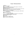
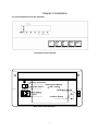
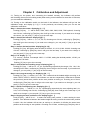
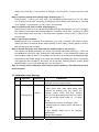
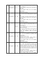
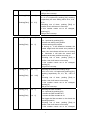
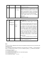
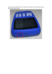
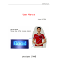
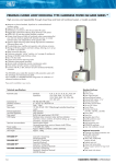
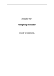
XK3190- A7
Weighing indicator
USER MANUAL
Directory
Chapter 1. Main Specification................................................. ............................,,..................2
Chapter 2 Installation…………………………………………………......……………,….………..3
Front and Back View of Indicator…………………………………......………………,……………..3
Connecting Loadcell to Indicator………………………………......………………,……….………..4
Keyboard Functions………………………………………………......……………,………….………4
Chapter 3 Calibration & Adjustment…………………………......…………….…,……………….5
Chapter 4 Operation……………………………………………......…………….…,..……………..10
.
Chapter 5 Errors & Information………………………………......…………………….….……...11
Chapter 6 Chargable battery………………………………......………………….…….…….……11
Chapter 7 Maintenance………………………………………......………………….…….….……..12
1
Chapter 1 Main Specification
◆Model: A7
◆Accuracy Grade: Ⅲ Class
◆A/D converting theory and sampling rate: double integration, 10-15 times/time
◆Maximum inner codes: 500000 codes/time
◆Non-linearity: ≤0.01% F.S.
◆Stimulating voltage for the loadcell: DC +8V, the maximum input signal is about 16 mV
◆Loadcell quantity: 1 load cell, 4 pins, (no long distance compensation)
◆Temperature coefficient on F.S: ≤8 PPM/C
◆Display: 6-bit LED, 0.56 inches in height, 6 status indicating lights, 3 battery charges
indicating lights
◆Keyboard: 5 slight-touch keys
◆Power supply: (1) AC 187-242 V, 50 HZ
(2) Built-in chargable battery 6V, 2.8 AH (2 pcs in serial connection)
◆Operating temperature and humidity: 0-40C, ≤90% RH
◆Storage temperature: -20--+50C
◆Fuse: 500mA
◆External dimension: 265× 190× 170mm
◆weight: 1.53kg (not including the battery)
2
Chapter 2 Installation
2.1 Front and back view of the indicator
Front View of the Indicator
Battery start button
Repair-proof Battery
Ship-like Switch
( 12V / 2.2AH)
Calibration Switch
Power Socket
Fuse
Loadcell Socket
Back View of the Ibdicator
3
2.2 Connecting loadcell to indicator
Please connects the line as following graphs
-E
c
h
Shield
d
e
i j k
f
End of Display
h +E
k +IN
+E
-IN
+IN
Excitation Power Supply +
Excitation Power Supply -
c-E
g
End of Load-cell
Signal Input+
j -IN
g Shield
Signal Output-
Connection of the load cell
◆You must cut off the power when connecting the loadcell, and the connection must be reliable.
◆After connecting the loadcell, you should fasten the plug with screw-driver.
◆Loadcell and indicator are static sensitive devices, you must adopt anti-static measures during
operation. You must mount the lightening rod in thunderstormm frequently happening area.
2.3. Keyboard Functions:
[Zero]:
Pushing this key, you can perform zero-setting, and the “Zero” light is on, otherwise it does not
work.
[Tare]:
Pushing this key, you can take the currently displayed weight as tare, “Tare” light is on.
[+] :
Pushing this key will add the presently loaded weight into accumulation memory, ‘+’ light is on, it will
display the total accumulated weight for 2 seconds, then displays total accumulated times for 2
seconds. ‘+’ light is off, it returns to weighing mode.
[CH]:
This key is used during calibration.
[ C ]:
Pushing this key, the indicator will display [C-Add] for 2 seconds, and will delete the accumulated
weights, then returns to Weighing Mode.
[ C ] [ + ]:
Pushing both keys at the same time, the indicator will display the inner codes, the maximum inner
code is 20 times of the selected division counts. Pushing both keys once more, the indicator will
return to Weighing Mode.
4
Chapter 3
Calibration and Adjustment
3.1 Turning on the power, and connecting the loadcell correctly, the indicator will perform
self-checking, then turns into working mode (After turning on the indicator for more than 10 minutes,
you can make the calibration).
3.2 Turning on the calibration switch on the back of the indicator, the indicator will go into the
calibration mode, and display [n,****](**** is the previously set number), then you can set the
calibration coefficients.
Step 1: choose the counts: displaying [n, ****]
Pushing [CH] key, **** will be 2000, 2500, 3000, 4000, 5000, 6000, 7500 optional, choosing
one of them, confirming by [Tare] key, then it will go to the next step. If you need not to change
the counts, you can push [ C ] key to go to the next step.
Step 2: choose the intervals: displaying [E, *]
Pushing [CH] key, * will be 1, 2, 5, 10, 20, 50, choosing one of them, confirming by [Tare] key,
then it will go to the next step. If you need not to change it, you can push [ C ] key to go to the
next step.
Step 3: choose decimal position: displaying [d, 0.0]
Pushing [CH ] key, the display after the letter d will be 0, 0.0, 0.00, 0.000. 0.0000, choosing one
of them, confirming by [Tare] key, then it will go to the next step. If you need not to change it,
you can push [ C ] key to go to the next step.
Step 4: F.S. display: [***.**]
F.S. =counts × interval, for example: 3000 × 5 =15000, setting the decimal position, 150.00: you
will get the Full Scale.
Pushing [ C ] key to go to the next step.
Step 5: confirm the zero-tracking range: displaying [02 *.*]
Pushing [CH ] key, *.* will be 0.5, 1.0, 2.0: representing respectively the range: 0.5e, 1.0e, 2.0e,
choosing one of them, confirming by [Tare] key, then it will go to the next step. If you need not to
change it, you can push [ C ] key to go to the next step.
Step 6: zero range at turning on: displaying [02, ***]
Pushing [CH ] key, *** will be 0.10, 0.20, 1.00. It means that the loaded weight at turning on is
within 10%FS, 20%FS, 100%FS, the indicator can set zero respectively. Otherwise it will take
the previously stored zero position as the zero position at turning on. choosing one of them,
confirming by [Tare] key, then it will go to the next step. If you need not to change it, you can
push [ C ] key to go to the next step.
Step 7: Select zero adjusting rate: displaying [03 *.*]
Push [CH] key, *.* will be 0.1, 0.2, 0.3: representing respectively the zero adjusting rate 0.1e,
0.2e, 0.3e. Choosing one of them, confirming by [Tare] key, then it will go to the next step. If you
need not to change it, you can push [ C ] key to go to the next step.
Step 8: Keeping the zero position or not: displaying [04 *]
Push [CH] key, * will be 0 or 1: 0 means not storing zero position, 1 means storing the zero
position. If the difference between the loaded weight at turning on and the stored zero position
is within 10e, the indicator will set zero at turning on, otherwise it will take the stored zero
position as the turning on zero position. Choosing one of them, confirming by [Tare] key, then it
5
will go to the next step. If you need not to change it, you can push [ C ] key to go to the next
step.
Step 9: Selecting manual zero-setting range: displaying [05 .**]
Push [CH] key, .** will be 0.02, 0.04, 0.08, 1.00: representing respectively 2%, 4%, 8%, 100%
F.S. Choosing one of them, confirming by [Tare] key, then it will go to the next step. If you need
not to change it, you can push [ C ] key to go to the next step.
Step 10: Selecting the filter constant, displaying [Lb *]
Push [CH] key, * will be 1 or 2, representing respectively the filter constant is 8 or 16. The bigger
this number is, the slower the renewing speed is. Choosing one of them, confirming by [Tare]
key, then it will go to the next step. If you need not to change it, you can push [ C ] key to go to
the next step.
Step 11: Set the zero position
Displaying [CAL] for 2 seconds, then displaying [ no Load], checking if the scale is empty,
waiting for about 10 seconds till the scale returning to zero stably, pushing [Tare] to confirm,
then you can go to the next step.
Step 12: Set the Full Scale (It is better that the loaded weight is near the F.S.):
The indicator will display [000.000], the first bit from the left will twinkle, pushing [ + ] will move
the twinkled bit from left to right, pushing [CH] will increase 1 on the twinkled bit, inputing the
actual loaded weight by hand. It is important to wait for 10-20 seconds till the displayed digits
are stable ( If the loaded weight is too small, the indicator will display [Err 08] for 3 seconds).
The bigger the filter constant is, the longer you should wait. Pushing [Tare] to confirm, [END]
appears finally. If you do not need this step, you can push [ C ].
Step 13: Turning off the calibration switch (move to down position), the calibration process
will be finished.
3.3 Calibration steps (listing):
Step
Operation
Displaying
1
2
Turning on the calibration switch at the back of
indicator (move to upper position)
Pushing [CH]
[n ****]
[n 3000]
Pushing[Tare]
3
Explanation
Pushing [CH]
[E
**]
Selecting counts:
2000, 2500, 3000, 4000, 5000, 6000, 7500
optional by pushing [CH] key. (When you
choose counts =7500, and E=2, pushing
[CH] ,the CH light below the window is on at this
time, you will get 15000 counts, ie, n’=15000,
E’=1)
Choosing one of them, for example: 3000
pushing [Tare] to confirm, then it will return to
next step.
If this number needs not to be changed,
pushing [C ]
Will get into next step.
Selecting the interval:
6
4
5
1, 2, 5, 10, 20, 50 optional by pushing [CH].
For example: 5
pushing [Tare] to confirm, then it will return to
next step.
If this number needs not to be changed,
pushing [C ]
Will get into next step.
Pushing[Tare]
[E
5]
Pushing [CH]
[d
0.0]
Pushing[Tare]
[dc
Pushing [ C ]
[***.**]
0.00]
[150.00]
6
7
Pushing [CH]
[01
**]
Pushing[Tare]
[01
0.5]
Pushing [CH]
[02
*.**]
Pushing[Tare]
[02
0.20]
Selecting the decimal position:
0, 0.0, 0.00, 0.000, 0.0000 optional by pushing
[C].
For example: 2 bits after decimal position (0.00)
pushing [Tare] to confirm, then it will return to
next step.
If this number needs not to be changed,
pushing [C ]
Will get into next step.
Full Scale display:
After you select n, E, and decimal position, you
can get the F.S.
If you confirm the F.S. you can go to the next
step by pushing [C].
If you do not confirm the F.S, you can turn off
the calibration switch and turn on it again, and
make the calibration again as above
mentioned.
Selecting the zero tracking range:
0.5, 1.0, 2.0 optional by pushing [CH],
representing
respectively 0.5e, 1e, 2e.
Choosing one of them, pushing [Tare] to
confirm, then it will return to next step.
If this number needs not to be changed,
pushing [C ]
Will get into next step.
Zero setting range at turning on:
0.10, 0.20, 1.00 optional by pushing [CH]:
meaning repectively that when the loaded
weight at turning on is within 10%, 20%, 100%
F.S, the indicator will set zero. Otherwise it will
take the previously stored zero position as the
zero position at turning on.
Choosing one of them, pushing [Tare] to
confirm, then it will return to next step.
If this number needs not to be changed,
7
pushing [C ]
Will get into next step.
8
9
10
11
Pushing [CH]
[03
*.*]
Pushing[Tare]
[03
0.3]
Pushing [CH]
[04
*]
Pushing[Tare]
[04
0]
Pushing [CH]
[05
*.**]
Pushing[Tare]
[05
0.04]
Pushing [CH]
[Lb
*]
Pushing[Tare]
[Lb
2]
Choosing zero setting rate:
0.1, 0.2, 0.3 optional by pushing [CH]: meaning
respectively the zero setting rate is 0.1e, 0.2e,
0.3e.
Choosing one of them, pushing [Tare] to
confirm, then it will return to next step.
If this number needs not to be changed,
pushing [C ]
Will get into next step.
Storing zero position:
0 or 1 optional by pushing [CH].
0 means not storing zero position.
1 means storing zero position.
At turning on, if the difference between the
loaded weight and the stored zero position is
within 10e, the indicator will set zero at turning
on. Otherwise it will take the stored zero
position as the zero position at turning on.
Choosing one of them, pushing [Tare] to
confirm, then it will return to next step.
If this number needs not to be changed,
pushing [C ]
will get into next step.
Selecting the manual zero setting range:
0.02, 0.04, 0.08, 1.00 optional by pushing [CH];
meaning respectively 2%, 4%, 8%, 100% of
F.S.
Choosing one of them, pushing [Tare] to
confirm, then it will return to next step.
If this number needs not to be changed,
pushing [C ]
Will get into next step.
Selecting the filter constant:
1 or 2 optional by pushing [CH].
1: means the filter constant is 8.
2: means the filter constant is 16.
The bigger the filter constant is, the slower the
renewing speed is.
Choosing one of them, pushing [Tare] to
confirm, then it will return to next step.
If this number needs not to be changed,
8
pushing [C ]
Will get into next step.
12
Pushing[Tare]
[CAL ]
[no Load]
13
14
Pushing [ + ]
T
Pushing [CH]
[000.000]
Pushing[Tare]
[***.**]
[END]
Deciding the zero position:
Displaying [CAL] for 2 seconds, then it will
display [no load] automatically, checking if the
scale is empty,waiting for about 10 seconds till
the scale returning to zero stably, pushing [Tare]
to confirm, then you can go to the next step.
If this number needs not to be changed,
pushing [C ]
will get into next step.
Setting the F.S:
It is better that the loaded weight is near the
F.S.
The indicator will display [000.000], the first bit
from the left will twinkle, pushing [ + ] will move
the twinkled bit from left to right, pushing [CH]
will increase 1 on the twinkled bit, inputing the
actual loaded weight by hand. It is important to
wait for 10-20 seconds till the displayed digits
are stable ( If the loaded weight is too small, the
indicator will display [Err 08] for 3 seconds).
The bigger the filter constant is, the longer you
should wait. Pushing [Tare] to confirm, [END]
appears finally.
If you do not need this step, you can push
[ C ].
Turning off the calibration switch (move to low
position), the calibration is over.
Note:
You can turn off the calibration switch and quit the paramater setting process at any time during the
calibration process.
In the calibration process above mentioned, for the step1-step 10, pushing [ + ] will go directly to
step 11, ie setting the zero position. If you do not calibrate, pushing [ + ] will finish the calibration.
3.4 Selecting the loadcell:
3.4.1 Loadcell sensitivity: 2mV/V.
3.4.2 Actual load should be 60%-80% of the rated load capacity.
3.4.3 Loadcell resistance: 350 Ω
3.4.4 Loadcell zero position: ±1% F.S.
9
3.4.5 For example: platform scale 60 kgs: loadcell 100Kgf
platform scale 100 kgs: loadcell 150Kgf
platform scale 150 kgs: loadcell 250Kgf
platform scale 300 kgs: loadcell 500Kgf
TGT-500kg mechanical-electrical platform scale: loadcell 60 Kgf
TGT-1000kg mechanical-electrical platform scale: loadcell 120 Kgf
Chapter 4
Operation
4.1 Turning on
4.1.1 Turning on the AC power, the indicator will check its strokes automatically, then it enters into
the weighing mode. If using the chargable battery, you should push the start button first, then the
indicator will check its strokes automatically.
◆f the battery has not been used before, you should charge the battery fully before you use the
battery.
4.1.2 At starting, if the indicator deviates from zero point, but still within the zero setting range, the
indicator will set zero automatically, zero light is on; If it is out of the zero setting range, you should
adjust the zero position again, or calibrate it again.
4.2 Manual zero setting:
4.2.1 Pushing [Zero], the indicator will go to zero, and the zero light is on.
4.2.2 If displayed weight deviates from zero point, but within the zero range, you can use [Zero] to
set zero, otherwise [Zero] will not work.
4.2.3 You are allowed to set zero only when the stable light is on.
4.3 Tare:
In the weighing mode , if the displayed weight is positive and stable, you can push [Tare] to reduce
the displayed weight as tare, the Tare light is on.
4.4 Accumulating and deleting:
In the weighing mode , pushing [ + ] , the indicator will display the total accumulated weight
(including the decimal position).
4.5 Insufficient voltage indication:
When the battery voltage is low, the low battery light is on, the display at the window will twinkle. In
this case you should turn the ship-like switch to ‘o’ to protect the battery. Continual using will result
in the further decrease in battery voltage, the indicator will cut off the battery.
4.6 Turning off
You should cut off the AC power line after you turn off the indicator.
In battery working mode, you can turn off the ship-like switch if you want to stop working.
10
Chapter 5
----------------
Error Indication
loaded weight is over F.S.
Err 03
inputing A/D number exceeds maximum number.Checking the loadcell
capacity and connection.
Err 05
inputing A/D number is too small, checking the loadcell connection.
Err 08
loaded weight at calibration process is too small ( not near the F.S).
Err 11
accumulated weight > 999999, or accumulated time > 99. reserving
the last unexceeded value.
Chapter 6
Chargable Battery
6.1 Turning on the AC power, the indicator will charge the battery automatically. So if you do not use
the battery frequently, you should take the battery out. If you think the automatic charging time from
AC power is too slow, you can buy from our company the specially designed charger, which can
charge the battery from outside indicator. Note: red end is +, black end is -. Wrong connection will
destroy the indicator.
Note: the built- in battery should be fully charged before it is used for the first time.
6.2 Only when you turn off the AC power, and push start key, the battery works, and the 3 battery
lights will be on. The indicator will cut off the battery when only one battery is on., at this time you
should charge the battery at once.
6.3 When you use the battery first time, you should charge the battery for 20 hours in order to
prevent the low voltage resulted from the self leakage of the battery.
6.4 If you do not use the battery for a long time, you should charge the battery for 10-12 hours for
each 2 month to prolong the using life of the battery.
6.5 The battery is the easily exhausted products, and is not granted the free guarantee.
11
Chapter 7
Maintenance
7.1 To guarantee indicator clarity and using life, the indicator shouldn’t be placed directly under
sunshine and should be set in the plain space.
7.2 The indicator can’t be placed into the place where the dust pollution and vibration are
serious.
7.3 Load cell should connect with indicator reliably, and the system should be well connected into
ground. The indicator must be protected from high electrical field and high magnetic field.
◆In order to protect the operator ,indicator and relevant device, you should mount lightning rod in
thunderstorm frequently happening area.
◆Load cell and indicator are static sensitive device, you must adopt anti static measures.
7.4 It is strictly forbidden to clean the case of indicator with intensive solvents (for example:
benzene and nitro oils)
7.5 Liquid and conducting particle should not be poured into the indicator, otherwise the electronic
components will be damaged and electric shock is likely to happen.
7.6 You should cut off power supply of indicator and relevant device before you pull-in and out the
connecting line of indicator and external device.
◆You must cut off power supply of the indicator , before you pull out connecting line of the load cell.
7.7 During operation, if trouble occurs, operator must pull off the power supply plug immediately,
and user should return this indicator to our company for repair. Non-weighing manufacturer should
not repair it, or by yourself, otherwise further destruction may happen.
7.8 The storage is not granted the free repair guarantee, because it is easily exhausted products.
◆In order to prolong using life , please charge the cell fully before using it.
If you don’t use the indicator for a long time, you must charge the cell every two month and for
eight hours/each charging time.
◆Moving or installation must be carefully taken and must avoid strong vibration, impact and bump
in order to protect the storage cell from being damaged.
7.9 From invoice date, the indicator has a one-year free repair period. If any non-artificially obstacle
about the indicator happens under correct using conditions within this period, the user is allowed
to send the product with its guarantee card (of the correct number) back to our corporation for free
repair. The indicator shouldn’t be taken apart, otherwise free guarantee will be cancelled.
12