1
Work Order 2 Final Report
A Human Factors Study of Information Dissemination and Display for
the Flight Standards Service
prepared by
Galaxy Scientific Corporation
Atlanta, GA 30345
prepared for
William T. Shepherd
Ms. Jean Watson
Federal Aviation Administration
Office of Aviation Medicine
Washington, DC 20591
(unpublished report, 1995)
Acknowledgments
This program was sponsored by the Federal Aviation Administration. Technical program
management was provided by Dr. William T. Shepherd, Program Manager, Office of Aviation
Medicine. This program was conducted under contract DTFA01-94-C-01013, Work Order #2.
The authors of this report (Michael Merriken, Richard McIntosh, Sameer Bhagwat, and Keith
Noll) would like to thank AFS personnel Danny O'Harrow, John Fodermaier, Mel Shuck, John
Bent, Beotis Wright and David Harper for their insights and comments during this program. The
authors would also like to thank Jean Watson of the Office of Aviation Medicine for her
assistance and support.
Chapter One
Review of Current Information
Sources and Displays
1.1 Summary
The Flight Standards Service (AFS) is interested in the efficient collection, analysis, and
dissemination of data among operators, manufacturers, and the government in its effort to
maintain aviation safety. New research and development efforts like the Performance
Enhancement System (PENS) have demonstrated that the use of new technologies with refined
software can improve the manner in which the AFS manages safety related data.
The following is a description of a detailed study of several AFS database systems to determine
the state of the existing information systems. The study consisted of several meetings with
information managers and Aviation Safety Inspectors (ASIs) from various Flight Standards
District Offices (FSDOs) across the country. These meetings focused on the usage, strengths
and weaknesses of the AFS database systems.
The study resulted in a number of significant findings:
•
An initial survey identified the Flight Standard Automation System (FSAS) as the
most heavily used system by the ASIs and their managers; therefore, this study
focused primarily on FSAS because of its wide use.
•
Many of the other database systems are rarely used.
•
During the discussions with the ASIs, the only strength that was identified was
that the database systems contained a wealth of data. This was quickly followed
by a complaint about how difficult it was to access this data and some concerns
about the integrity of the data.
•
While there are many weaknesses in these systems, there are some common
weaknesses across the systems.
1.2 Purpose
This document identifies and briefly explains the functionality of the systems that are most
frequently used by ASIs. The report details the weaknesses of these systems and highlights the
new systems' enhancements identified during the study.
There are three major systems being used by AFS personnel. These systems are the Flight
Standards Information System (FSIS), the Logistics and Inventory System (LIS) and the
Integrated Personnel and Payroll System (IPPS). Each of these major systems contains a number
of subsystems. The focus of this study was on the subsystems in FSIS, since these subsystems
are widely used by the ASIs. The LIS and IPPS systems were beyond the scope of this study.
1.3 Systems Description and Weaknesses
FSIS was formerly known as the Aviation Safety Analysis System (ASAS). However, the ASAS
subsystems were reorganized under the current title in 1991.
FSIS is a nationally distributed information network designed to collect, store, and organize
aviation safety data under a single system. It consists of a number of separate subsystems
designed to improve the AFS' ability to gather and analyze aviation safety data within all AFS
offices nationwide. Through improved computer operations, information management and
administration, FSIS provides data support to identify present and potential safety issues,
supplies management with the information necessary to use its resources more effectively, and
gives each office the ability to respond to internal and external requests for information.
The majority of the FSIS subsystems reside on an IBM mainframe computer, while a smaller
number of these subsystems reside on Data General computers and on personal computers (PC)
running on local area networks (LAN). Each FSDO has PCs running on a LAN. Each Regional
Office has PC and a Data General computer. The main computing center in Plano, Texas has an
IBM mainframe, PCs, and a Data General computer.
The systems on the Data General computers are currently being moved to the client/server
environment. In this environment a powerful PC functions as a database server which services
the requests of applications running on client PC workstations.
The following is a brief description and a list of weaknesses of the subsystems that constitutes
FSIS. FSAS and its related subsystems are covered first, because they are the largest
component. All other systems are covered in alphabetical order after FSAS.
1.3.1 Flight Standards Automation Subsystem (FSAS)
FSAS is a set of subsystems used in Flight Standards field offices to store and organize
inspection and safety data, ranging from certifications to routine inspections. It consists of the
following subsystems:
•
Program Tracking and Reporting Subsystem (PTRS)
•
Operations Specification Subsystem (OPSS)
•
Vital Information Subsystem (VIS)
•
Job Aids Subsystem
•
Key Manager Subsystem
•
Planning Subsystem
•
Operational Training Needs Assessment (OPNA)
FSAS is a PC-based system that operates locally on a Novell Netware 3.11 local area network.
It uses the Paradox database system. Data entered locally into the system at a Flight Standard
District Office (FSDO) are uploaded daily to the mainframe in Plano, Texas. The data are then
verified and redistributed to the appropriate field offices on the following day. Data residing on
the mainframe are stored in the national database. Therefore, field offices can exchange
information through the national database. Data transfer between the mainframe and the LAN is
semi-automated. The network administrator has to initiate this process on a daily basis.
Program Tracking and Reporting Subsystem (PTRS)
PTRS was designed to enable the FSDOs to compile and track information gathered by PTRS
datasheets. These datasheets are data entry forms used by ASIs to document their work before
they enter it into PTRS. PTRS allows AFS personnel to efficiently forecast, plan, monitor
inspector activities, monitor work program accomplishments, and monitor trends affecting
aviation safety. It is the most frequently used system in FSAS.
Operations Specification Subsystem (OPSS)
OPSS was designed to automate the process of Operations Specifications document preparation
for commercial air carriers and other air operators. It standardizes the document format across
AFS regions and FSDOs and it provides inspectors with up-to-date documents for more accurate
inspections for Federal Aviation Regulations (FAR) Part 121 and Part 135 Air Operators. The
OPSS system works in conjunction with the VIS system.
Vital Information Subsystem (VIS)
VIS was designed to enable FSDOs to maintain and analyze information about air operators, air
agencies, designated airmen, check airman, facilities, and organizations engaged in
non-certificated activities. This system interacts with the OPSS system by way of providing an
air operator record. OPSS then attaches an Operations Specification document to the air
operator record.
Job Aids Subsystem
The Job Aids Subsystem was designed to enable FSDOs to print job aids (similar to checklists)
for the PTRS, OPSS and VIS Subsystems. These job aids help the inspector in gathering
information and performing inspection activities.
Key Manager Subsystem
The Key Manager Subsystem was designed to enable FSDOs to generate a list of key personnel
associated with air operators who lost their certification as a result of an emergency revocation.
Planning Subsystem
The Planning Subsystem was designed to enable FSDOs to develop a surveillance work plan for
the fiscal year. The Planning Subsystem builds a unique surveillance work plan for each FSDO
based on the data stored locally in VIS. The Planning Subsystem examines the contents of VIS,
and assembles a set of records that identifies the activities that a FSDO will perform over the
course of the next fiscal year. The surveillance work plan identifies the number of air operator,
air agency, and airman inspections that a FSDO expects to conduct over the course of the fiscal
year. The Planning Subsystem allows FSDOs to maintain both required surveillance activities
and planned activities. Required surveillance activities are assigned by each regional office and
represent the minimum number of inspections that a FSDO must do under the National Program
Guidelines (NPG). Planned activities represent the number of inspections that FSDOs can do
over and above the inspections required by national guidelines. The Planning Subsystem
generates a work program for inspectors. This system then updates the PTRS system with these
work programs.
Operational Training Needs Assessment (OPNA)
OPNA was designed to allow district offices to use data in the FSAS databases to determine the
training needs of its ASIs. The subsystem is accessed on a yearly basis. It uses the information
in the PTRS and the VIS files to determine if additional ASI training is required over the course
of the next fiscal year.
1.4 FSAS Weaknesses
The following is a list of weaknesses that were identified by ASIs and information managers
during the analysis of FSAS. In general, most users feel that the subsystem is outdated and that
it is often difficult to use.
•
Poor Data Quality: The quality of the data in the FSAS database is very poor. It
is often difficult to produce reports on a particular topic because the required data
for the report is often not a required entry. This is directly related to the data
entry constraints of the subsystem. FSAS needs to provide more data entry
guidance to its users. To alleviate this problem some FSDOs create customized
data entry forms that guide the local ASIs in terms of required data entry fields.
For example, the Harrisburg FSDO has generated several of these customized
data entry forms. Examples of these forms are shown in Appendix A. The form
illustrating data entry into PTRS for a complaint requires the fields Activity
Number, Call Up Date, Designator and Investigation Number. PTRS does not
require the fields Call Up Date and Investigation Number. Without these fields,
reports generated from the PTRS database on how quickly complaints are being
addressed by a FSDO are useless because the date of the complaint (Call Up Date
field) is unknown. Similarly, the data entry form for an incident (shown in
Appendix A) requires the fields Activity Number, Call Up Date, Designator,
LOC/Departure Point and Investigation Number. PTRS does not require Call Up
Date, LOC/Departure Point or Investigation Number. Again, generating an
incident report on the date and location of an incident without data in these fields
is of little value. In order to support their reporting needs, FSDOs sometimes use
certain data entry fields for purposes that were not intended. Hence, the data from
one FSDO to another could be very different which defeats the AFS primary goal
of having homogeneous data across FSDOs.
•
Lack of Integration of Subsystems: FSAS in general needs to be more tightly
integrated. An area in the system where this problem is evident is in the VIS and
OPSS Subsystems. If a user removes an air operator from VIS, the user must also
perform a second task to remove the related operational specification document
from OPSS. Another example is, if a user adds a new aircraft to OPSS, the user
must also add the information for that aircraft to VIS. Because FSAS is not well
integrated users occasionally forget to add or delete the data in all the required
areas of the system. This problem leads to data integrity problems which add to
the poor state of the FSAS data.
Even within a subsystem database duplicate data entry is a prevalent problem. An
example of duplicate data entry is in VIS, where identical inspector related data are
required both in the Air Operator and Environment files. Again, this often leads to data
integrity problems, because users sometimes forget to enter this data in all the appropriate
places.
The ASIs and other AFS users often use Windows software packages such as Microsoft
Word and Excel along with FSAS on a daily basis. In order to access FSAS while the
Windows software is running, the user must exit Windows, then start FSAS. Both
systems cannot run simultaneously. A clear need exists to have all AFS systems running
under a single integrated environment; this will cut down on the time and effort it takes to
access important safety related systems.
•
Poor User Interface: The data entry screens for comments are too difficult to
access. In order to access these screens, a user is required to step through several
intermediate screens. This is often inconvenient because frequently data entry is
required only on the first screens and on the comment screens.
A spell checker would be a tremendous benefit for all comment sections in FSAS. This
will eliminate the chance of ASIs inadvertently saving unreadable comments to the
system. This functionality will aid in improving the quality of data in the FSAS
databases.
The Ad-hoc reporting function within the FSAS System is too difficult to use. In order to
use the Ad-hoc function, knowledge of the Paradox Database System is required. Due to
its complexity, many ASIs do not use this feature. If an ad-hoc report is needed, the
network administrator typically is asked to generate this report. Because of the delay and
inconvenience involved, many ASIs do not request these reports. Several ASI's indicated
that if this feature were easier to use, they would use it.
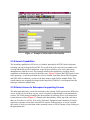
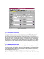
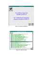
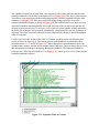
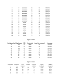
An example of the existing FSAS Query system is shown in Figures 1 through 3 (these
figures use simplified representations of the actual screens to facilitate paper
reproduction). Figure 1.1 illustrates the first screen that a user sees when the Query
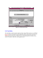
function is selected from the main FSAS menu. Figure 1.2 shows the Ad-Hoc Report
Maintenance screen. On this screen, if a new report is to be created, the user would first
select the change function, select an existing report then modify that report to create the
new report. The user would then design a query that meets the criteria for the report.
Screen 3, which is represented by Figure 1.3 would then be accessed. On screen 3, the
user would select the fields of interest to be printed on the report and the position in
relation to other fields. As the diagrams illustrate, the ad-hoc reporting system is time
consuming and extremely difficult to use. To use the system, an in-depth knowledge of
the Paradox Database System and the structure of the FSAS databases are required.
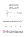
Figure 1.1 Ad-hoc Report Screen #1
Figure 1.3 Ad-hoc Report Screen #3
Figure 1.2 Ad-hoc Report Screen #2
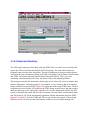
•
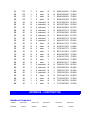
Limited Search Capabilities: The searching capabilities in FSAS are very
limited. For example, searching can only be done by Record ID in PTRS. If a
record needs to be retrieved for update and the Record ID is not known, it will be
very difficult for an ASI to find the appropriate record. In this situation a special
query will have to be run against the database to identify the record. An example
of the current search capabilities is shown in Figure 1.4. This example illustrates
the search function in the PTRS system. Future upgrades to FSAS should include
a generic search function that will allow a search on any field within the
subsystem.
Figure 1.4 PTRS Search Screen
•
•
•
Poor Communication Facility: A FSDO does not have an efficient method of
responding to another FSDO's comments in FSAS. For example, suppose a
FSDO does an inspection on an aircraft that has its Certificated Holding District
Office (CHDO) elsewhere. If the FSDO that did the inspection indicates in the
PTRS Subsystem that a problem exists with the aircraft, there is no direct way for
the CHDO to communicate back to the FSDO that the particular problem was
corrected. To add to the problem, the CHDO does not readily know that a
response is required. Many FSDOs generate a report that lists all the records that
need responses. However, this list usually consists of several records. A great
deal of time is required to go through this report. Many ASIs currently handle
this problem by placing a telephone call to the CHDO to inform the responsible
party of the problem. Some form of automated two-way communication system
between FSDOs is needed.
More Help Facility: Although FSAS provides help in relation to valid entries
for some fields, it needs to provide more field related help.
Job Aids Subsystem: The Job Aids subsystem needs to be updated. In addition
to needing more job aids, existing job aids need to be updated. An example of
this would be adding fax numbers on forms generated by the Job Aids Subsystem.
Although the Job Aids Subsystem is not being used much by experienced ASIs, it
is often used by new ASIs in order to guide them through entering data in FSAS.
•
OPSS Issues: OPSS is too rigid. Adding or updating operating specifications
cannot be done by a user. The software itself has to be modified in order to add or
update additional specifications. An example of this problem would be adding
de-icing specifications to the operations specification document for an air carrier.
There is no way for a user to add this additional specification to OPSS. FSDOs
currently handle this problem by manually typing the additional specification and
appending it to the printed document. This is an obvious inconvenience because
each time the same specification is needed it will have to be retyped.
The Text Editor, used for entering comments in the subsystem, is extremely difficult to
use. One obvious inconvenience with this editor is that it splits lines within words
instead of between words.
When entering data into the system, the cursor (focus) does not automatically move to the
next field if the current field is fully populated. The user has to use the "enter" key to get
to the next field.
•
OPNA Functional Issue: The entire FSAS system is inhibited when the
Operational Training Needs Assessment (OPNA) runs. Before OPNA runs all
users are required to exit the FSAS system. OPNA requires exclusive use of the
FSAS databases to generate its reports.
•
Key Manager Subsystem: is not used by most FSDOs, if at all.
1.5 Summary of Remaining FSIS Subsystems
A formal and complete review of the following subsystems would be beyond the level of support
provided for this subtask. Therefore, a brief review of each available subsystem is provided with
a few comments given to us by the ASIs who had exposure to these subsystems.
1.5.1 National Flight Standard Automation Subsystem (NFSAS)
NFSAS is a read only mainframe subsystem which retains the FSAS data uploaded from all
FSDOs. It is functionally equivalent to FSAS. However, NFSAS contains data from all the
national field offices. National users can access this subsystem to view this information and
produce reports. On-line manipulation of data at the national level (on the mainframe) is not
allowed. NFSAS consists of the following subsystems:
•
National Program Tracking and Reporting Subsystem (NPTRS)
•
National Vital Information Subsystem (NVIS)
•
National Operations Specifications Subsystem (NOPSS)
•
Regional Automated Mainframe Planning System (RAMPS)
National Program Tracking and Reporting Subsystem (NPTRS)
NPTRS contains the latest available PTRS data from all Flight Standards offices. This
subsystem allows users to view or print all reports that show inspection and surveillance
activities. In addition, reports concerning total work program accomplishments and National
Program Guideline data can be easily accessed.
National Vital Information Subsystem (NVIS)
NVIS contains the latest available VIS data from all Flight Standards offices. This subsystem
allows users to view or print all records and reports concerning reference data on air operators,
air agencies, airmen, aircraft, and facilities.
National Operations Specifications Subsystem (NOPSS)
NOPSS contains the latest available OPSS data from all local Flight Standards offices. This
subsystem allows users to view or print all records and reports concerning operations
specifications.
Regional Automated Planning System (RAMPS)
RAMPS is a mainframe system which uses NVIS and NOPSS to create a required surveillance
plan for each FSDO. This surveillance plan represents the minimum number of inspections that
a FSDO must do under the NPG. RAMPS examines NVIS and NOPSS files, generates the
required items and sends this information to each FSDO. This occurs at a date late in the fiscal
year to ensure that all FSDOs have the opportunity to review the information they store on the
local level.
1.5.2 Automated Federal Aviation Regulations Subsystem (AFARS)
AFARS is a mainframe subsystem which provides users with the capability to access the latest
available full text of all Federal Aviation Regulations (FARs) as well as all FARs which were in
effect during the past two years. The system also allows users to view or print a particular
section of a FAR, search for all FAR references on a particular topic or word, and find citations
and cross references within the regulations. AFARS is a read only system, therefore, users do
not have the capability to add, update, or delete data. This system resides on the IBM mainframe.
1.5.3 Airworthiness Directives Subsystem (ADS)
ADS is a mainframe system which contains the full text of all the current and the historical
Airworthiness Directives (AD). An AD is a document issued by the Federal Aviation
Administration that specifies a required safety-related maintenance procedure or set of
procedures for a specific aircraft or aircraft component. An inspector can expediently research
the Airworthiness Directives applicable to the particular aircraft that is about to be examined and
have that information presented on-line. The inspector can then view or print the researched
information. This system resides on the IBM mainframe and replaces the slower microfiche and
hard copy filing methods.
1.5.4 Automated Exemption Subsystem (AES)
AES is a mainframe system which provides users with access to information about completed
exemption projects required by District, Regional, and Headquarters offices. This system makes
it possible for users to centrally record and maintain current, expired, and denied exemptions. It
also allows them to query and correlate information about petitions and exemptions. The system
is mainly used by aviation safety inspectors and regulators to obtain access to exemption
information relating to a specific FAR. The system is used by regulators to study trends. The
regulators use it to identify cases where an exceedingly large number of exemptions are
requested for a particular regulation, which would suggest that the regulation needs to be
modified. The AES system resides on the IBM mainframe.
1.5.5 Accident/Incident Data Subsystem (AIDS)
AIDS is a mainframe system which provides automated support for the collection and analysis of
data related to aircraft accident and incident occurrences. The information supports FAA
certification and rule making activities. AIDS contains specific information relevant to each
accident or incident including data on the aircraft, the crew, the type of flying, the weather
conditions, the location of the accident or incident, facilities, injuries and causal factors. The
system allows users to produce reports on specific aircraft accidents and incidents as well as
summary reports. This system resides mainly on the national Data General computer in Plano,
Texas. AFS personnel access AIDS by dialing up the Data General computer in their regional
office, which in turn will automatically connect them to the system on the national Data General
computer. AIDS summary information is also available on the IBM mainframe. This summary
information is copied twice per week from the national Data General computer to the IBM
mainframe.
1.5.6 Enforcement Information Subsystem (EIS)
EIS is a mainframe system which allows field and regional offices to monitor pilots and air
operators violations. The subsystem provides automated support for violation and enforcement
actions. EIS allows users to add, update, or change enforcement data, to access data regarding
the violator or the violation, and to track events and people involved in an investigation. The
subsystem resides on all nine regional Data General computers. It also resides on the national
Data General and IBM computers in the form of summary files. The subsystem at the national
level does not contain the full data for each region.
1.5.7 Integrated Safety Information Subsystem (ISIS)
ISIS is a mainframe interactive querying system which provides fast and easy access to much of
the information in other FSIS subsystems regarding air operators, aircraft, and airmen. ISIS can
be reached from most screens by pressing the F6 function key. The subsystem accesses live data
from 12 AFS systems. Some common systems accessed by ISIS are Airworthiness Directives,
Comprehensive Airmen Information, Accident/Incident Data, and Enforcement Information. In
fact, EIS summary information is accessed through ISIS. This subsystem resides on the IBM
mainframe.
1.5.8 Master Minimum Equipment List Subsystem (MMELS)
MMELS is a mainframe system which automates the process of creating, revising, approving,
and distributing the text of aircraft Master Minimum Equipment Lists. MMELS are documents
that specify under what conditions a given make and model of aircraft may be permitted to
operate temporarily with specified items of equipment inoperative. These MMELs serve as the
basis for approving related operator-specific minimum equipment lists. This subsystem resides
on the IBM mainframe.
1.5.9 National Aircraft Registration Information Subsystem (NARIS)
NARIS is a read only mainframe subsystem which allows users to access aircraft registration
information and related historical data at the National Aircraft Registry and to then display or
print the information. This subsystem also provides users with the capability to review aircraft
registration data, request copies of microfiche aircraft records, and query the subsystem to
identify aircraft for which complete identification is not available.
1.5.10 Policy Subsystem (PS)
The Policy Subsystem is a mainframe subsystem which provides users with rapid access to the
full text of Orders and Notices, Handbooks, Handbook Bulletins, Flight Standards Information
Bulletins, Advisory Circulars, Policy Memoranda, Preambles, Legal Interpretations, Air Carrier
Operations, Bulletins, and Medical Guidelines. It allows documents to be selected, viewed or
printed by document number or according to user-specified criteria. PS also allows the text of
rules associated with a document to be viewed by directly accessing the Automated Federal
Aviation Regulations Subsystem. This subsystem resides on the IBM mainframe.
1.6 Subsystems Weaknesses
When MMELS are updated for a particular aircraft, the FSDOs often do not get the
documentation specifying what section of the document was updated. An ASI can spend hours
comparing the newly acquired MMEL with the local MEL to find the discrepancy
Each subsystem, including FSAS, requires a different User Id and password for access. Some
inspectors and managers have up to six different User Ids and passwords. They often write these
User Ids and passwords down on paper for reference. This defeats the purpose of having system
security.
Although these mainframe subsystems contain a tremendous amount of data, many users of these
system do not know how to access the data and they often do not know that the information
exists.
Access to the mainframe subsystems needs to be more reliable and efficient. Access is currently
made via modem and often the connection to the mainframe is denied because all of the
available ports are busy. Under the current configuration, only a certain amount of concurrent
connections are allowed on the mainframe. Therefore, if all connections are busy, access is
denied until a connection is released.
1.7 Miscellaneous Systems
The following is a list of systems that are commonly used by FSDOs. Each FSDO is unique in
the way it uses these systems and in the number of systems it uses.
1.7.1 Automated Correspondence Express (ACE)
ACE Documentation is a Windows based program which provides AFS personnel with the
capability to use a standardize letterhead for correspondence. It works in conjunction with
Microsoft Word. This program is a customized package which was specifically designed for use
at the FSDOs.
1.7.2 CUFF
CUFF is a Windows-based budgeting program which allows AFS personnel to efficiently
manage their yearly budget.
1.7.3 Travel Manager Plus
Travel Manager Plus is a commercial Windows-based product which combines travel regulation
automation, electronic document processing and government forms generation into one
easy-to-use software package. It allows AFS employees who travel to accurately fill out their
travel paperwork on their PCs in a fraction of the time it takes to do it manually. This enables
them to get their reimbursements in a more timely fashion.
1.7.4 South West Regional Data Tracking System (SWRDTS)
SWRDTS is a Windows-based product which allows AFS personnel to use a standardized
letterhead for correspondence. Like the ACE product, this system works in conjunction with
Microsoft Word and it was designed for use at the FSDOs. Several FSDOs use SWRDTS
instead of ACE.
1.8 Known Systems Enhancements
During this evaluation several efforts to improve the AFS database systems were identified. The
following items were at different stages of completion. These items could have an impact on any
future system enhancements plans. Recommendations were added to these efforts based on the
information pointed out to us by the ASIs and their managers.
•
Client/Server Environment: CACI is presently building a database
infrastructure for AFS. This infrastructure will allow all AFS systems to
eventually migrate to the client/server environment with the consent of the
owners of these systems. Great care will have to be taken to make sure that all
related systems are migrated together and that all essential AFS hardware and
software contractors are well briefed on any migration efforts.
This migration effort will place the AFS data into three separate database systems
(Mainframe, Paradox and Oracle). The migration effort will most likely be handled by
multiple contractors. Therefore, some design standards need to be established to ensure
that the user interface from one application to another will have a similar look and feel.
•
Two-Way Communication: The two-way communication system between
FSDOs that was mentioned earlier in this document is currently being worked on.
Therefore, any effort to enhance FSAS will have to take this work into
consideration.
•
Redesign of EIS: The EIS system is presently being redesigned. The subsystem
is being moved from the Data General computers to the client/server
environment.
•
Redesign of AIDS: AIDS is presently being redesigned. It is being down-sized
to the client/server environment. It will run on Microsoft SQL Server using the
Windows NT operating system. AIDS will then be referred to as the Improved
Accident/Incident Database System (IAIDS).
•
FSAS Subsystems: Two FSAS subsystems have been moved to the Microsoft
Windows and client/server environments. VIS and OPSS have been converted to
run on the Microsoft SQL Server platform. The subsystems are written in
Microsoft Access. They are still being beta tested and they have not yet been
released. The SQL-based VIS and OPSS are functionally equivalent to the
existing DOS-based systems. They do not address the weaknesses identified by
this study.
1.9 Conclusion
While the AFS systems contain a vast amount of data, many systems, especially FSAS, have
become just a large repository of data. The data in these systems are difficult to access because
the tools to access them are not user friendly and the quality of the data is poor. Therefore, ASIs
very rarely use these data for analysis purposes. One ASI summarizes the problems with FSAS
with the following statement: "We are currently working for FSAS; we need to get FSAS to
work for us." FSAS was designed over 10 years ago and it no longer accurately reflects the
functions of the AFS. Data entry fields that were not required years ago, are now required.
Ready-made reports that were useful some time ago are no longer used. In addition, the
subsystems in FSAS do not function as one integrated unit. Therefore, maintaining data integrity
across subsystems has become a massive effort. Many FSDOs have come up with a temporary
solution to help improve the quality of the data at the local level, while other FSDOs do not have
the time or the resources to address this problem.
This study, while keeping the overall informational goals of the AFS in mind, focused heavily on
the user's perspective. A wide cross section of AFS users were interviewed and were observed
as they used the systems. The majority of the identified weaknesses are unique to FSAS since it
is the most frequently used system. These weaknesses negatively impact the way AFS personnel
perform their work. Therefore, by enhancing FSAS and by accurately addressing these
weaknesses, a number of important benefits will be realized:
1.
Users will be required to spend less time interacting with the system and will have
more time to address other safety related issues,
2.
Data stored in FSAS will be easily accessed to assist the ASIs in conducting
inspections or planning efforts,
3.
ASIs will take more initiative in using the system because they were directly
involved in the analysis and will be directly involved in the design,
4.
And the quality of the data in the FSAS databases will be vastly improved by
having standardized data entry requirements.
Chapter Two
Development and Evaluation of Improved Display
Prototypes
2.1 Summary
The purpose of this task was to develop prototype displays to demonstrate how existing Flight
Standards Service (AFS) reference documents and databases would benefit from the application
of a user-centered design approach to display design. Two prototyping efforts were completed
under this subtask. The first effort was to develop a user interface that would address the
problem issues with the Flight Standards Automation System (FSAS) that were identified in a
related subtask. The second effort was to develop a multimedia prototype of an Inspectors
Handbook. These prototypes capitalized on graphical user interface (GUI) technologies and
Human Factors research on information presentation (color, formatting, direct manipulation,
etc.). These prototypes emphasized ease of use and information utilization. The research team
evaluated these prototypes in cooperation with aviation safety inspectors (ASIs).
2.2 Database User Interface Prototypes
The detailed study of the Flight Standards Service (AFS) database systems, as documented in the
previous chapter (Chapter 1), outlined the manner in which the ASIs interact with the numerous
database systems provided for their use. As a result of this study, several inherent weaknesses
that are unique to the Flight Standards Automation System (FSAS) were identified. Please refer
to Chapter 1 for a detailed description of these weaknesses.
A prototype user interface display was developed to demonstrate how the FSAS user interface
could be improved. During development, several trips were made to the Atlanta Flight Standard
District Office (FSDO) to demonstrate the prototype and to gather feedback on our efforts. The
responses received from the ASIs and managers were positive. They felt that the functionality
which the prototype provided would be very helpful in allowing them to perform their daily
tasks.
During the detailed study of the AFS existing database systems, we were informed that the AFS
is planning to upgrade the existing Paradox database system to a client/server environment in the
near future. In this environment, processing is split between powerful servers and desktop
machines. A powerful computer usually functions as the database server, which services the
clients' requests. A less powerful desktop computer running a Windows-based system functions
as a client and makes request to the database server. The prototype demonstrates some of the
benefits that the AFS will realize when it makes the conversion to the client/server database
environment.
The prototype is not a fully functional FSAS system. It merely demonstrates how some of the
FSAS weaknesses can be addressed. The prototype only emphasizes enhancements to the
Program Tracking and Reporting Subsystem (PTRS) and Vital Information System (VIS).
However, the issues addressed in these two subsystems are applicable to the other FSAS
subsystems as well. The following is a detailed description of the prototype, the weaknesses it
addresses, and how these enhancements will benefit the AFS.
2.2.1 FSAS Weaknesses Addressed
To address all of the weaknesses identified in Chapter 1 would be beyond the level of support
provided for this activity. The prototype demonstrates enhancements to a subset of the FSAS
weaknesses identified. The following is a list of the items that the prototype covers.
1.
Demonstrate FSAS improved functionality in the Windows environment.
2.
Provide data entry guidance to users within the Windows-based FSAS.
3.
Demonstrate a more efficient search function within the Windows-based FSAS.
4.
Demonstrate an easier way to access supporting subsequent screens (e.g.,
comment screens) within the Windows-based FSAS.
5.
Demonstrate a more efficient text editor for entering comments within the
Windows-based FSAS.
6.
Demonstrate how selected Windows-based FSAS subsystems interact if the
subsystems were more tightly integrated.
7.
Demonstrate how selected Windows-based FSAS subsystems function if the
database was normalized resulting in the elimination of duplicated data between
the subsystems.
8.
Demonstrate an improved ad-hoc reporting function. This new reporting function
was not demonstrated by the prototype, however, various ad-hoc reporting tools
that work within the Windows and client/server environments were investigated
and are documented in this report. These issues are explained in detail in the
following sections.
2.2.2 FSAS in the Windows Environment
The current implementation of FSAS is a DOS-based, Paradox-driven application that is not
compatible with the Windows operating environment. The ASIs and other AFS users often use
several Windows-based software packages along with FSAS on a daily basis. Both FSAS and the
Windows Operating System cannot operate simultaneously on the ASI's desktop computer.
Therefore, if a user is in FSAS and he/she needs access to a Windows-based software package,
the user will be required to exit FSAS and then start the Windows Operating System.
This prototype demonstrates how a Windows-based FSAS system would operate in a
client/server environment and how it would benefit the AFS. Because this FSAS prototype
adheres to standard Windows design, users who are already familiar with Windows will also be
familiar with the functionality of the prototype. Each subsystem is designed using the MS
Windows standards for a common look and feel thus ensuring similar functionality. Hence, very
little time will be spent retraining users to use this system.
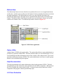
The prototype attempts to guide the users through the system. Emphasis is placed on ease of use
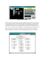
and on presenting the users with valuable information when appropriate. Figure 2.1 shows the
main FSAS screen. From this screen all FSAS subsystems (PTRS, VIS, OPSS, KEYMGR,
JOBAIDS, and PLANNING) are accessible. The user-id and user information displayed is
acquired from the Flight Standard Electronic Office system (FSEO). The FSEO system provides
a single point of user login. Please refer to Chapter 4 for a detailed description of the FSEO
software. The prototype demonstrates how the user can be aided by presenting the most
frequently used choices. Figure 2.2 represents the VIS main entry screen which contains the
most often used functions. The screen allows the user to select the appropriate form from the
form type section and then to select whether to create a new form or open an existing one. The
description on the bottom of the screen describes the form type that is selected. The options
presented on the main screen (Open, New) can also be accessed from the Activity menu option.
Figure 2.3 is a representation of the activity menu. The Edit menu offers the standard edit
options available in the windows environment such as Cut, Copy, Paste, and Clear.
Figure 2.1 Main FSAS screen
Figure 2.2 VIS main entry screen
Figure 2.3 VIS activity menu
These options under the Edit menu allow data to be copied within or between applications. The
Reports menu option will provide access to pre-defined reports and to the ad-hoc reporting
system. The Tools menu provides quick access to PTRS and VIS. The Tool Bar located at the
top of the screen provides the same functionality as the menu items, but it presents the choices in
a graphical form. A balloon help function was integrated into the prototype so that whenever the
cursor is moved over an item on the Tool Bar, a brief description of the item is displayed. Figure
2.4 illustrates this functionality. The Tool Bar can also be customized by the user. It can be used
to gain quick access to frequently used applications. Therefore, some items on the Tool Bar, such
as the one depicted in Figure 2.5, are optional.
Figure 2.4 Balloon help function
The AFS intends to convert all of the major safety-related database systems to run within
Windows. When this takes place, the ASIs and other AFS users will no longer be required to exit
one subsystem in order to start another. This will reduce the time and effort it takes to access
these subsystems. In addition, by having all major systems running under the Windows
environment, data can be easily transferred within and across subsystems. For example, if an ASI
needs to write a memo in MS Word and he/she needs to reference information in FSAS, the ASI
can transfer this information from the appropriate subsystem to the memo directly by using the
standard cut and paste functionality in Windows. Another advantage of having all major
database systems running in the Windows environment is that several safety-related subsystems
can be run simultaneously. Therefore, a user can potentially have PTRS, VIS, and OPSS running
at the same time, which is important if the user needs to copy information across subsystems.
The only limit to the amount of subsystems that can be up and running simultaneously is the
amount of memory that is installed on the user's desktop computer.
Figure 2.5 Optional tool bar
The AFS will eventually migrate its major applications to the Windows environment, but this
will take time. This will result in some systems continuing to reside on the mainframe computers
before the transition is complete. However, access to the mainframe via Windows will not be a
problem because there are several software packages on the market that effectively address this
issue. Procomm for Windows and IBM Personal Communication System are two such packages
that will allow users working in the Windows environment to access the mainframe. This will
allow a user to cut and paste information from mainframe applications to Windows-base PC
applications.
2.2.3 Data Entry Guidance
Although the existing FSAS provides some help in relation to valid entries for some fields, it is
not enough and it is often too generic. The Windows-based FSAS prototype demonstrates how
data entry guidance can be provided to the users. The prototype emphasizes two ways of
providing guidance to the users.
1. Easy Access to User Manual Data
First, it moves frequently used data from user manuals to on-line computer files and provides
users with an easy and efficient method of accessing the data in these files. For example, Figure
2.6 illustrates the activity numbers selection screen in the PTRS prototype. If the activity number
is known, it can be entered directly. If it is not known, a search can be performed on a particular
topic and then the appropriate activity number can be selected. This can be easily accomplished
by entering the topic in the Find Next field, click on the Find Next button or by using the ALT F
key combination. The subsystem will find the first occurrence of the topic and display a symbol
representing a book. Clicking on the book will display the appropriate activity numbers relating
to the specified topic. At this point the appropriate activity number can be selected by
highlighting it and clicking on the OK button.
Figure 2.6 Activity Numbers Selection Screen in PTRS Prototype
2. Field Sensitive Information
Second, as the user moves to a field, a message is displayed on the bottom of the screen detailing
the valid entries for that particular field. Figure 2.7 illustrates this functionality. Each field has
an associated help text, so the user will always have an idea of what to do next.
Figure 2.7 Example of Field Sensitive Functionality
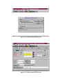
2.2.4 Search Capabilities
The searching capabilities in FSAS are very limited, particularly in PTRS. In this subsystem,
searching can only be done by Record ID. If a record needs to be retrieved for an update or for
viewing and the Record ID is not known, a special query will have to be run by the system
administrator to find the record. The prototype addresses this problem by providing search
capabilities on fields that are more useful to the users. Figure 2.8 shows the PTRS search screen
in the prototype. A search can be done by Activity Number, Start Date, Record ID, Designator
and NPG fields. In addition, a search can be done using a single field or multiple fields. This
search function was originally developed in the Inspector's Field Kit. It was integrated into the
prototype with minor modification.
2.2.5 Easier Access to Subsequent supporting Screens
The subsequent data entry screens for comments in the existing FSAS system are too difficult to
access. In order to access these screens, a user is required to step through several intermediate
screens. The FSAS prototype handles this inconvenience by allowing access to all subsequent
screens from any screen. Figure 2.7 illustrates this functionality. On the top of the each screen
there are five tabs (1a Activity, 1b Activity, Personnel, Equipment, and Comments). Each tab
represents a separate screen in the current FSAS system. In the prototype, if access is needed
only on the 1a Activity screen then on the comment screen, it will be a matter of just clicking on
the appropriate tabs.
Figure 2.8 PTRS Search Screen
2.2.6 Text Editor
The Text Editor is used for entering comments. In the existing FSAS systems it is very difficult
to use. One obvious inconvenience is that it splits lines within words instead of between words.
Figure 2.9 depicts a text editor resident in the FSAS prototype which provides most of the
functionality of a word processor. It allows users to cut, copy and paste text within or across
systems. In addition, it splits lines in the appropriate place.
Figure 2.9 Duplicte Data Entry
2.2.6.1 Duplicate Data Entry
The ASIs log the majority of their daily tasks into PTRS. However, there are several tasks that
require the ASIs to enter data into multiple FSAS subsystems. The same data elements are
frequently entered across these subsystems. The task of adding an air operator requires that an
ASI enters the same information relating to the FAR, Designator Code and Name, and Personnel
into PTRS, VIS and the Operation Specifications Subsystem (OPSS). This is very time
consuming, often frustrating to the users, and it also leads to data integrity problems.
The prototype remedies this situation by allowing the user to selectively choose to transfer data
between subsystems, if the task requires it. For example, if a user wants to add an air operator,
he/she would first access the PTRS. Figure 2.10 shows the main startup PTRS screen. The user
would then select the 'Initiate VIS' option on the PTRS startup screen because this task requires
duplicate data entry across subsystems. After the user saves the information in PTRS, the VIS
system is automatically started and the FAR, Designator Code and Name, and Personnel Name
and Title fields in VIS will be automatically populated with the information entered in PTRS.
Figures 2.11 and 2.12 show the PTRS and VIS screens with the data entered. If the user had
chosen to access VIS first, the same functionality would have been available through VIS.
Figure 2.10 Main Startup PTRS Screen
x
Figure 2.10 Main Startup PTRS Screen
Figure 2.12 VIS Screen
2.2.7 Subsystems Integration
The prototype demonstrates how the FSAS subsystems can be more tightly integrated when
running in a client/server environment with normalized databases. This allows data to be
migrated from subsystem to subsystem because all subsystems will have a common source of
data. The prototype also allows any subsystems to be started from within another subsystem. For
example, while a user is in PTRS, he/she can access VIS or OPSS by accessing the Tools menu
and then select the appropriate system. At this point the user will have multiple systems running
at the same time. The user will not be required to exit the current subsystem he/she is in before
accessing another subsystem.
2.2.8 Ad-hoc Reporting tools
The ad-hoc reporting function resident in the existing FSAS is extremely difficult to use. In order
to effectively use the ad-hoc function, a user needs an adept knowledge of the Paradox Database
system. Many ASIs like the idea of an ad-hoc function, and they indicated that they would use
this feature more if it was easier to use.
As was mentioned earlier, the AFS has decided to move to a client/server environment.
Therefore, we looked at several ad-hoc reporting tools that could benefit the AFS and that could
be easily integrated into any Windows-based database system. These tools all run in the
client/server environment. Because access to a client/server environment was not available
during the investigation period, the evaluation of these tools was based on documentation
retained from the various software vendors and trade journals. The following is a brief
description of three reporting tools investigated as well as their relative merits to the AFS.
Crystal Reports Professional 4.0
Crystal Reports from Seagate Software Company includes a report wizard that will walk a user
through the process of creating various types of reports, such as standard columnar, cross-tab,
and summary reports. In many cases a user can create a report in three simple steps. First, the
user chooses the type of report he/she wants. Second, the user selects the fields and drags and
drops them to the appropriate place on the report formatter. Finally, the user generates the report.
Crystal Reports can benefit both the developers and the end-users alike. Developers' data
dictionaries can be created, which store pointers to the databases and connection types that are
used most frequently. The dictionaries could be passed on to the users, and let the users run
ad-hoc reports without having to understand complicated table relationships and data types.
Crystal Reports also has an excellent charting tool that provides users with the capability to view
data in a graphical form.
ReportSmith for Windows 2.5
ReportSmith by Borland International Inc. is very similar in terms of functionality to Crystal
Reports. However, ReportSmith is the fastest reporting tool of the three. It also provides a more
extensive and flexible field criteria selection box. Therefore, very complex reports can be
generated without any programming effort. Like Crystal Reports, fields can be placed on the
report formatter by dragging and dropping them to the proper location. However, ReportSmith
automatically calculates the best fit for the report and lays out the data on the screen accordingly.
The users' ability to manipulate the report design is far better than any of the other two products.
It also contains an integrated charting tool, which allows a user to view data graphically.
R&R Report Writer 6.0
R&R Report Writer by Concentric Data Systems Inc. was the most difficult to use of the three
products. It was a bit difficult to select the fields a user wanted on a report in R&R. Unlike the
other packages, there was no way to select all the fields at once to place them on the report
formatter. The report formatter in R&R is the weakest of the three, providing only the traditional
banded-style-report design tool. This formatter is very similar to the one in the current FSAS
ad-hoc reporting system. R&R Report Writer does not provide an integrated charting tool. To
create a graph, a user would have to export the data into a software package that supports
graphics, such as Microsoft Excel.
Crystal Report and ReportSmith are two reporting tools that can definitely benefit the AFS users.
These tools run in the Windows-based client/server environment and will allow users to generate
ad-hoc reports by simply selecting the type of report, the necessary fields, and then generating
the report. Prior knowledge of a programming language or database structures is not required.
These reporting tools can effectively hide the complexity of table relationships and data types
from users. Users are able to extract data from the database in the form of a report or graph
without being concerned about where and how the data is stored.
2.3 Inspector's Handbook Multi-Media Prototype
There is a tremendous amount of information contained in the Inspector's Handbooks utilized by
the ASIs. The ASIs currently use a paper version of these documents to assist them in
performing their duties. Recently, versions of these handbooks have been produced in digitized
form and distributed on CD-ROM. These digitized handbooks have several time-saving features
such as word/phrase search, linking, and database navigation functions.
Flight Standards Service (AFS) aviation safety inspectors (ASIs) can increase their productivity
by being provided with a tool to quickly and comprehensively access information contained in
the Inspectors Handbooks. Such information serves as reference material and basic guidelines to
the ASIs. A prototype of the Inspectors Handbook software was developed to address this need.
This prototype incorporated several time-saving features such as word/phrase search, document
linking, and efficient navigation. Multimedia technology was integrated into the software to
provide the inspectors with a subjective evaluation in situations where traditional methods of
instruction fail.
This task challenged the research team to determine if the ASIs could benefit from the intelligent
integration of multimedia technology (primarily video and audio) in the handbooks, and if so,
how it would best be implemented.
2.3.1 Requirements Definition
There are many factors to be considered in creating a multimedia-inspectors handbook. First, the
system must be fully useable and understandable to the aviation safety inspector. This will be
insured with a user-centered design approach: capitalizing on rapid prototyping and interactive
development driven by user evaluation and feedback. Second, the system must be developed on
computer technology that is compatible with FAA's current and evolving systems. This will be
ensured by working closely with the Training and Automation Committee, and with other FAA
research projects like PENS. Third, the multimedia information system should be easily
modified to incorporate updates and document evolution. This will be insured by the use of
commercial off-the-shelf software development tools.
Presently the ASIs have a choice of either carrying the handbooks with them in the field or
leaving them behind. If the ASIs carry the handbooks with them, they find the handbooks are
bulky and cumbersome to carry. The ASIs must then sift through large amounts of information.
It is a mammoth task to search for something unless the location is specifically known.
Cross-referencing documents also becomes a major problem. Another option is to leave the
handbooks behind and just look up the information needed before leaving the office. This is not
always possible. In such situations, the ASIs could jot down the information required and return
to the office to look it up. This approach leads to inefficiency and delays as the information is
not available on hand to look up. This could present a problem in certain situations where time is
of the essence, for example in a ramp inspection situation. The ASIs would then rely on their
past knowledge or experience which may not be up to date with the most recent revision of the
handbooks.
Current multimedia technology can be used to deliver the Inspectors Handbook on-line,
complete with an efficient searching function and hyperlinks between relevant documents. This
will reduce the ASIs physical and mental workload. The integration of multimedia features also
has the potential to provide refresher training and/or initial training based on an individual
inspector's need. The entire software could be put onto a portable notebook computer equipped
with a CD-ROM which the ASIs could carry with them on the field. This way the ASIs would
have instant access to the most current handbook information. This would enable them to
perform their tasks more efficiently.
Through a series of meetings and discussions with ASIs, it was determined that the most
promising application of multimedia information technology would be in support of tasks where
the ASIs are required to make qualitative judgments based upon visual observations. Less
experienced ASIs and all ASIs who perform some type of visual assessment could benefit from
an on-line video or graphic to aid them in their decision-making process. Another promising
application of this technology is to provide background or tutorial information concerning a
complex or detailed issue.
2.3.2 Methodology
The Inspectors Handbook software prototype was developed using the principles of
human-centered design. The tasks of the ASIs were first analyzed. During interviews with the
ASIs, several observations were made as to how the handbooks were actually used by the
inspectors. The following is a list of ASIs' activities observed and how handbooks were used:
•
Looking for a specific reference by either using the Table of Contents to look up a
specific chapter and/or browsing throughout the document looking for related
information.
•
Placing bookmarks at useful or frequently referenced sections in the document.
•
Annotating a specific paragraph or section.
•
Referencing another document related to the topic of interest.
•
Physically inserting related reference documents in the handbook at appropriate
locations.
•
Comparing change notices with the old version of the document to determine
what has changed and how it effects their activities.
The above observations revealed the need for developing a computer based software which
would aid the ASIs in their day to day tasks. This entailed putting the Inspectors Handbooks
on-line with various features such as search, hyperlinks, and multimedia which would help the
ASIs navigate through the handbooks. For the initial prototype, it was decided to include a
subset of the Inspectors Handbooks which would serve to demonstrate the capabilities of the
software. The PC platform was chosen for developmental work as it was compatible with the
FAA's current and evolving systems. The necessary digital documents, figures, and videos were
created and integrated to ensure a comprehensive prototype. The initial prototype was developed
and shown to the ASIs to get their feedback. The prototype was then cycled through several
iterations based on their suggestions. Emphasis was placed on interactive development driven by
user evaluation and feedback. Different scenarios were developed and evaluated for inclusion in
the prototype. The prototype was also shown to different people internally to test for usability
and to debug it.
The software prototype is PC compatible. The software prototype development environment was
Windows for WorkGroups 3.11 running under MS DOS 6.2. The programming was done in
Visual Basic 3.0 and Borland C++ 4.0 with support from Windows SDK 3.1. Database support
was provided by MS Access 2.0 and Hypermedia Information System (an internally developed
database.)
2.3.3 Description
2.3.3.1 General
When the Inspectors Handbook software is started up, a screen similar to the one shown in
Figure 2.13 is displayed. Handbooks 8300-10 and 8400-10 can be accessed in the prototype. By
directly placing the cursor on one of the titles and selecting it will bring up the table of contents.
The table of contents uses an outline type of index. For example, when the user first enters the
screen, only the volumes contained within that handbook are displayed. Selecting a particular
volume by moving the mouse over it and clicking on it brings up the list of chapters contained
within that volume as showed in Figure 2.14.
Figure 2.13 Inspectors Handbook
Figure 2.14 Table of Contents
The expanded volume has an 'open book' icon associated with it which indicates that the items
contained within the volume have been displayed ('b' in Figure 2.15). The other volumes have a
'closed book' icon associated with them indicating that they could be expanded to display their
contents ('a' in Figure 2.15). Selecting a particular chapter brings up the list of sections
contained within that chapter as shown in Figure 2.15. The section items have a 'book leaf' icon
associated with them indicating that the user could select any of the section items and directly
navigate to the associated text ('c' in Figure 2.15). If the user selects another volume at this time,
the earlier list of chapters and sections is automatically collapsed and the new list of chapters is
displayed. The icons associated with each list entry automatically change to denote the updated
status of each item.
Clicking on a particular section of the Table of Contents will bring up the text related to that
section as shown in Figure 2.15. The current position in the handbook is indicated by three
information bars ('a', 'c', and 'd' in Figure 2.17, which display the current handbook name, the
current volume number, and the current chapter number and name. The user always has access to
this information which helps in navigating through the handbook. The Inspectors Handbook
prototype has a fully functional toolbar ('b' in Figure 2.17,) which gives access to all the features
contained within the software.
Figure 2.15 Expanded Table of Contents
Figure 2.17 Handbook Information Screen
The expanded figure of the toolbar shows all the buttons contained in the toolbar (Figure 2.16)
The 'Inspectors Handbook Bookshelf' button can be used to access a different handbook. The
'Table of Contents' button displays the complete break up of the current handbook. The 'Find'
button is used to display the search dialog box. The 'Find Again' button is used to find a
particular search term again. The 'History' button can be used to return to a previously navigated
document. The 'Annotations' button brings up a list of the annotations for the current chapter.
The 'Bookmark' button allows insertion/deletion of bookmarks. The 'Video Player' button brings
up the video player along with a list of available videos. The 'Figure Viewer' button brings up the
figure viewer along with a list of available figures. The 'Table Viewer' button is similar to the
'Figure Viewer' button. The 'Help' button brings up the help topics for the Inspectors Handbook
prototype (not yet developed.) The 'Exits' button closes the application.
Figure 2.16 Toolbar Functions
2.3.3.2 Multimedia Information
Many of the tasks performed by the Airworthiness ASIs are visual in nature, such as looking for
signs of corrosion, physical damage, and incomplete or improperly performed maintenance
actions. Supplemental multimedia information would assist in such activities if they are new to
an inspector or performed infrequently. Another use of multimedia information would be in
providing training/refresher courses.
For example, the Inspectors Handbook prototype has video clips on corrosion which explain the
corrosion process and describe the common areas where corrosion occurs. These clips could help
a new ASI in learning more about corrosion. An ASI inspecting the landing gear of a particular
aircraft may need more information about the procedures involved. The video clips related to
landing gear information could be brought up on screen and the video clip related to the aircraft
being examined could be played. These video clips would assist the ASIs in their inspection task.
Video Player: The video player (Figure 2.18) allows playback of video clips related to a
particular section in the document. The list of video clips is automatically selected based on the
current document context. For example, if the user selected a video hyperlink describing
corrosion, only the videos related to corrosion would be displayed in the list box. The time
counter shows the elapsed time.
Figure 2.18 Video Player
Similarly, graphics or pictures may provide more information than words alone. For example,
the severity of tire tread wear could be easily determined by comparing the acceptable tire tread
wear photographs with the actual wear. This acceptable tire tread wear photographs could be
easily accessed from the Inspectors Handbook software using the 'Figure Viewer' (Figure 2.19).
Figure Viewer: The figure viewer control (Figure 2.19) has the capability to display 'bmp', 'gif',
and 'pcx' format pictures. The picture control has a zoom range of 1% to 999%. Selecting a
figure hyperlink starts up the picture viewer and automatically loads up the relevant picture.
Figure 2.19 Figure Viewer
2.3.3.3 Software Specific Features
Hyperlinks: Three different types of hyperlinks have been implemented in this software. They
are text hyperlinks, figure hyperlinks and video hyperlinks. The software automatically
determines the type of hyperlink and executes the corresponding actions. Text hyperlinks allow
navigation between relevant documents. Figure and video hyperlinks bring up related figures and
videos.
Search function: The search function (Figure 2.20) has the option of searching through the
current section or through the entire book. Boolean searches are allowed in the search function.
Once the list of occurrences is brought up, it is possible to directly navigate to a particular
occurrence. The ASIs can again return to this window to pursue other hits from the search.
Figure 2.20 Search Function Dialog Box
History function: The history function (Figure 2.21) keeps track of user navigation through the
chapter. Each section that the ASI views is recorded by this function. This facilitates an ASI in
returning to a previously viewed section or switching back and forth between two or more
sections.
Figure 2.21 History Dialogue Box
Annotation function: The annotation function (Figure 2.22) allows users to annotate a particular
section or paragraph. A small annotation icon comes up wherever the annotation is made ('e' in
Figure 2.16). The table of contents is also updated to show that annotations exist for a particular
chapter by putting a small icon next to the chapter title (Figure 2.23,).
Figure 2.22 Annotations Dialog Box
Figure 2.23 Annotation Icon in Table of Contents
Bookmark function: The bookmark function allows users to define their own bookmarks at
useful or frequently referenced sections in the document. The users can access these bookmarks
by selecting them from the bookmark menu item (Figure 2.24,).
Figure 2.24 Bookmark Dialog Box
2.3.3.4 User Centered Features
To aid the ASI in using this application, a series of features were added based upon MS
Windows standards and related user-centered design research.
•
A toolbar complements all menu item entries for easy access to software
functionality ('b' in Figure 2.16). The complete functionality of the Inspectors
Handbook prototype can be accessed from the toolbar.
•
A status bar displays help information for the control over which the mouse
currently rests ('g' in Figure 2.16).
•
Another status bar displays the status of the application, whether it is ready for
user input or whether it is working on something such as a global text search ('f' in
Figure 2.16).
•
The cursor automatically changes to a 'hand' cursor over hot spots or hyperlinks.
•
To minimize user error, all the function buttons and menu items are grayed out
(disabled) if they cannot be used for a particular operation.
•
If the user is about to perform an irreversible action such as deleting an annotation
or exiting out of the system, the software always prompts for user confirmation.
•
If an error occurs anywhere, the software always displays a message as to the
nature of the error and corrective actions if any.
2.3.4 Conclusion
The Inspectors Handbook prototype would increase the productivity of the ASIs by allowing
them instant access to all the necessary documents. It would cut down on the delays associated
with accessing information and would make routine searches more efficient. It would further
serve as a refresher/training medium by showing relevant video footage to the ASIs if so desired.
Future enhancements to the software would include combining prototype with the Inspectors
Field Kit which would allow users to fill out requisite forms and look up information at the same
time. Another addition would be to link the FARs to the Inspectors Handbook prototype for
enhanced information retrieval. Finally, all of the information could be accessed remotely from a
central server which would help reduce the equipment carried around by the ASIs.
Future concerns include maintaining the digital handbook information current and updating the
various hyperlinks within the handbooks. A suitable method needs to be developed which would
automate the process of creating and updating hyperlinks from digitized data. By doing this, the
ASIs would have access to the most current information at any given time.
Chapter Three
Advanced Technologies for Display and Database
Automation
3.1 Summary
The objective of this activity was to investigate advanced technology tools for transferring data
into the Flight Standards Service (AFS) databases. A detailed study of the AFS database
systems and the manner in which the Aviation Safety Inspectors (ASI) interacted with these
database systems was completed in Chapter One. Based upon the results of this study, several
advanced technology tools were identified and investigated. These technology tools included
optical character recognition, personal digital assistants, and speech recognition. Each will be
explained in detail in this report.
3.2 Optical Character Recognition
The data an ASI collects follows a circuitous path before it is entered into the appropriate AFS
national database. Most ASIs today collect data during an inspection or investigation using brief
notes written down on a notepad. When they return to the office they fill out the appropriate
form(s) referring to the written notes from their note pads and their memory. The data from
these forms is then entered into a local database at the office, often by a data entry clerk. This is
a time consuming process that is prone to data entry errors of omission and commission. Time
and money would be saved and data integrity would be improved if the number of times the data
were handled was minimized. At some time in the future it is planned that the handling of the
data would occur once using a single point entry job aid like the Inspectors Field Kit (IFK).
Unfortunately this will not occur in the near future for all AFS offices. In the mean time, an
optical character recognition application would provide the means to reduce the number of times
the data were handled. With the help of it, data can be input into the computer by scanning the
raw data directly from the initial form. This study was undertaken to find out how accurate this
technology can be and what configuration(s) of software and hardware should be used to obtain
the best results. The process and the results of the study are discussed below.
Various Optical Character Recognition software products were investigated for this activity. We
identified 36 different OCR packages that were currently available. Features such as handwriting
recognition, form removal, image enhancement options, and de-skew capability were identified
as minimal OCR capabilities. In order to be compatible with the IFK we also looked for the
ability to support industry standard programming languages (Visual Basic and C) within the
Microsoft Windows operating environment. This would allow an OCR application to be tightly
integrated into existing, as well as future, AFS systems. These requirements reduced the number
of potential products to 12. Many of these had features that were not applicable to the proposed
AFS office environment such as form creation utilities, stand alone receive and send FAX
capability, batch scanning and classification algorithms, and graphic editing capabilities. The
cost of these additional features was not deemed necessary just to get the basic required OCR
capabilities. After reviewing product information and trade journal reviews, OMNItools by
Nestor Products was purchased and evaluated.
As with all technology assessment activities, this review of products is current as of March,
1995. The introduction of new technologies is continuous and a better product may be available
in the near future. We will continue to remain cognizant of these new systems as they are
introduced.
OmniTools
OmniTools, developed by Nestor Incorporated, accurately recognizes hand-written and
machine-printed characters from scanned or faxed images. In addition to character recognition,
the system identifies documents, resizes and straightens incoming faxes, removes preprinted
forms, automatically detects hand-printed and machine-printed words, reads optical mark (check
box) entries, and provides several output options including alternate choice characters. It
provides an Application Program Interface (API) for industry standard programming languages,
such as Visual Basic, and also allows handwriting recognition solutions to be developed from
Access, Excel, Foxpro, Lotus 123, and Paradox.
3.2.1 Recognition Process
The process of handwriting recognition using this product includes five steps: (1) preparing an
image file, (2) defining a zone definition form, (3) performing the actual recognition, (4)
displaying the results and (5) verifying the results. Except for the last, all of the steps can be
done with the OMNItools software.
3.2.1.1 Preparation of Image Files
Since OMNItools cannot prepare image files, a basic scanning product was used to create the
image file. This file contains the image of the hand-writing and form that will be recognized.
An image can be captured by a camera, a scanner, or some other devices. All the image files
used in this study were created using the Hewlett-Packard ScanJet IIc scanner and the Deskscan
II software1. Using this hardware and software combination, three attributes of the resulting
image could be modified: image file format, brightness, and resolution. These attributes are
commonly available to most scanners, and are discussed in detail below.
Image file format
OMNItools accepts either Paintbrush or Bitmap format files. Preliminary testing indicated that
there was no difference in recognition accuracy between these two file types. Since the size of a
Paintbrush file is usually four to five times smaller than the size of a Bitmap file, the image files
were stored in a PaintBrush file format. The number of colors used in a PaintBrush file can also
be set. Two color (black and white) PaintBrush files were used for all the tests in this study.
The reason for this decision is that OMNItools has difficulty interpreting PaintBrush files that
contain more than two colors.
Brightness
The Brightness attribute controls the contrast of an image. It is similar to the brightness control
used in a photocopier. The darker you set the brightness attribute, the more details you can see.
The range of the brightness scale for a ScanJet IIc scanner is from 0 (darkest) to 255 (lightest).
By trial and error, two values, 80 and 150, were chosen to be used in this study. When the
brightness is set to a value of 80, the scanned image is clear and sharp for both dark and light
color lines. When the brightness value is set to 150, dark color lines appear clearly, while light
color lines are not visible.
Resolution
The resolution is determined by the number of dots per inch (dpi) used to represent an image. In
DeskScan II, the dpi setting can be set as low as 12 dpi or as high as 1200 dpi. A setting of 100
dpi resolution was used in the beginning. It was quickly determined that this value was too low
because the image quality was very poor. A setting of 300 dpi was found to be the lowest setting
that produced a high quality image for character recognition in the image file.
The density of data on the original form is also very important. The data density cannot contain
too much data when the image is processed. How much is too much was determined
empirically. When the form's data density was too high, an error message "Image is too large
and complex" would be displayed. This phenomena was discovered during the initial
familiarization period. This situation did not occur during the actual evaluation.
It warrants repeating that the brightness and the resolution attributes discussed above are specific
to the scanner. They are not part of the OMNItools. Readers must keep this point in mind when
these scanner settings are discussed in context of the OMNItools attributes.
3.2.1.2 Form Definition
A zone definition form (ZDF) file contains information of how OMNItools should recognize the
image. The specific area or zone on the form that will contain data must be identified. You can
also specify more information about each zone and about the whole form so that the software can
carry out a more accurate recognition. There are three kinds of zones which can be defined in a
ZDF file: registration zone, data zone, and optical mark recognition (OMR) zone.
Registration zone
This zone defines static information that can be deleted from the scanned image using a feature
called Form Removal. Using a common tax form as an example, OMNItools would be able to
remove those printed boxes, lines, and characters from the tax form as the scanned image was
being processed. It would read the tax form as if it only contained the hand-writing of the
author. To use Form Removal, registration zones have to be defined and two forms must be
supplied: one blank form (called Master Form) and one form filled with data (Data Form). The
registration marks are used as anchors between the Master Form and the Data Form so that the
static data can be removed accurately.
Also, through trial and error it was found that 1)Form Removal worked best if the registration
marks were some simple shapes like small, filled-in squares and 2)Locating the registration
marks close together at the top third of the page provided the most accurate combination for the
Form Removal feature to function properly. Locating these marks was not an easy task. It was
discovered that characters or complex graphics cannot be used as registration marks. This would
result in an error saying "Can't find the registration mark".
Define data zones
Data zones are areas which contain the hand writing that needs to be recognized. A single form
can contain multiple data zones. Several attributes can be defined for each data zone, each of
them intended to specify the number/type of characteristics within a data zone which would
result in a higher rate of recognition accuracy. The attribute options available are:
I)
Hand print / Machine print.
Specifies whether the zone contains hand-writing, machine-print characters, or both.
II)
Characters Per Inch (CPI)
A data string typically has a constant letter spacing. If the number of characters per inch
is known in advance, it can be specified so that the software will locate each character
more accurately.
III)
Punctuation Marks
Some data strings may or may not contain punctuation marks. Setting attribute
"Containing Punctuation" to "none" will reduce the possibility of recognizing some
characters as punctuation marks if no punctuation exists.
IV)
Single Word, Single/Multiple Lines
The data format may be in one word, one line, or multiple lines. This option may help to
eliminate recognizing extra spaces and recognizing one character as two.
V)
Checking Context
If this is set, OMNItools uses an expert system for grammar in an attempt to guess the
next character based on the context of the words if there is any uncertainty about that
specific character. For instance, if the software is not sure whether the character is a 'v'
or 'u' following a 'q', it would identify the character to be a 'u' because of higher
grammatical probability.
VI)
Define Dictionary.
A Dictionary can be used (or defined) to restrict the word for a specific zone. For
instance, suppose a data zone is restricted to a dictionary that is defined as containing
only two words ("MALE" and "FEMALE"). If, for example, a word "MALA" (or
anything similar) was recognized, the word will be changed to "MALE" because of the
dictionary constraint.
VII)
Character constraint
It is usually known in advance what type of characters will appear in a data zone. For
example, A-Z, and/or 0-9, or some unique combination are valid ranges.
Optical Mark Recognition (OMR) zones
These zones are areas on the form designated for check boxes. It can be chosen to be either a
single radio box or a multiple choice group.
Form level information
There are some attributes which would affect the whole form. These options are:
I)
Form Removal - ON/OFF
If this option is set, the static data will be removed from the image.
II)
Remove long lines - ON/OFF
If this options is set, all the long lines will be removed.
III)
Restore/de-skew image - ON/ OFF
If this option is set, OMNItools will try to restore image by de-skewing some lines that
may have been skewed during the process of capturing the image from the source.
IV)
Drop-out ink - ON/OF
This option tells OMNItools whether the image to be recognized contains drop-out ink or
not.
V)
Result file format - ON/OFF
Result file format can be text, text with quotes, or ZRF (file format defined by
OMNItools). If the results are going to be verified using the OMNItools, the result file
format has to be in Zone Recognition File (ZRF) format.
3.2.1.3 Recognition
The actual recognition can be done by specifying the image file and the ZDF file. It usually
takes less than 10 seconds to finish one recognition with about 100 characters using a
Pentium-90 machine.
3.2.1.4 Results Display
OMNItools provides a tool to view the ZRF file. It can display the results of all the data and
OMR zones in a scrollable window. It can be chosen to show how accurate the recognition was
for each character. Threshold confidence levels can be set such that it will only show the
recognized character if the confidence level is higher than the specified value. Using this tool,
results can also be stored in a plain text file or copied to other Windows' application.
3.2.1.5 Verification
The verification tool allows users to see the recognition and the original data at the same time.
This allows the users to compare the results visually and correct any mistakes made by the
software. As mentioned before, the results have to be stored in ZRF file in order to use this tool.
The modified results can also be stored in the same ZRF file.
3.2.2 Methodology
3.2.2.1 Data Preparation
A modified version of the standard AFS form, Program Tracking and Reporting System (PTRS),
was used for all the tests. This form was created using a software application called VISIO.
There are a number of modifications made to the basic form in order to be suitable to be tested.
Four registration zones were defined. Data fields were enlarged to have a density of 6 CPI.
Letters within any check box were removed to avoid any confusion between these letters and the
actual hand-writing. The gray scale of boxes that surrounded the data fields were set to be the
lightest shade available in the VISIO application. This was done to minimize the interference
with the recognition process. The modified PTRS form is shown in the Appendix.
3.2.2.2 Data Collection
Ten Galaxy Scientific Corporation employees participated in this study. A sample form and a
blank form were given to each participant. They were instructed to copy the information from
the sample form to the blank for in their own handwriting. The sample form contains five class
of data that included every recognizable character:
1) Uppercase
: three sets of upper case alphabets (A-Z)
2) Lowercase
: three sets of lower case alphabets (a-z)
3) Digits
: five sets of digits (0-9)
4) Special
: three sets of special characters ("$( )+-/")
5) Checkmark
: thirty-six check mark zones
There are a number of attributes can be changed in the ZDF file that were discussed in previous
section. Some of these attributes remained fixed for the study while others were varied. The
following section lists the fixed and variable attributers.
Fixed attributes:
I)
Hand print / Machine print.
Handprint was used throughout the entire study.
II)
Punctuation
No data will contain any punctuation.
III)
Single line
All data was regarded as single line data.
IV)
No context checking
The sample characters were listed alphabetically, therefore context was not used.
V)
No dictionary defined
For the same reason as above, no dictionary was defined.
VI)
No drop-out ink
No drop-out ink was used.
VII)
Result file format
Text file format was used.
Variable attributes:
I)
Form Removal
The options tested were On or Off. The static data was removed from the image if "On"
was selected.
II)
Remove long lines
The options tested were On or Off. If " On" was selected then all the long lines were
removed.
III)
Restore/de-skew image
The options tested were On or Off. This attribute can only be used when Form Removal
is "Off", otherwise the error message "Can't find the registration mark" would occur.
VI)
Character constraint
This attribute only applies for the data zone. There are two kinds of constraints used in
the tests: restricted constraint and relax constraint. For the restricted constraint option,
the data zone was restricted to one of three settings:
•
alphabetic characters defined to be from A and Z;
•
digits defined to be from 0 and 9;
•
special characters defined to be anything (A-Z,0-9,$()+-/).
For relax constraint option, every data zone was defined to recognize all characters.
V)
Characters per inch (CPI)
This attribute only applies to the data zone. It can be set to any positive value. The data
form was originally designed for a character spacing of 6 CPI. Therefore this option was
set to either 6 CPI or 0 CPI for these tests. The 0 CPI option means that the characters
per inch attribute is undefined. In other words, the software has to locate the characters
by itself.
VI)
Brightness of the image
The options tested were 80 or 150.
There are a total of 48 possible combinations for above attributes. Table 3.1 illustrates the
options more clearly:
Table 3.1 Options
Attributes
Characters per inch
Options
0 (Undefined)
Form Removal
Remove Long Lines
6
Yes
Yes
Restore/de-skew image
No
No
Yes
No
Character Constraint
Restricted
(A-Z or 0-9)
Relaxed
(all characters)
Scanner Brightness
80
150
Ten sets of hand writing were collected. Each set of data was recognized using all 48
configurations mentioned above. The results were stored in text file format and printed out. The
printout were counted manually to determine the number of correctly recognized characters per
set of data.
3.2.3 Results & Analysis
For each configuration that represented the 48 unique combinations of variables, an average
percentage of accuracy was calculated across the ten participants. The data for each variable
attribute was divided into two groups (since each attribute has two options). A line graph was
plotted using these two groups. The difference between these two lines indicates how much the
specific attribute affects the recognition accuracy.
Since data zones and OMR zones have different attributes, their results were analyzed
separately. The results were illustrated with the graphs. It needs to be emphasized for the reader
that each graph represents a different set of configurations of variables to illustrate the effects of
each attribute. For example, Configuration 1 in Figure 3.1 may not be the same as the
Configuration 1 in Figure 3.2. Detailed information for each graph indicating configurations and
actual values can be found in the Appendix.
3.2.3.1 Data Zones Average results
Figure 3.1 shows the average results for each configuration. The table shows the corresponding
statistical values. Descriptions for each configuration are in the Appendix. There are several
rises and falls on the graph. They are caused by different variable attributes. The effects of each
attribute will be discussed individually.
Figure 3.1 Average results for each configuration
Character constraints
Figure 3.2 shows how the attribute Character Constraint affects the recognition accuracy. The
first eight configurations have a restricted constraint while the last eight configurations have a
relax constraint. There is a drop in accuracy (7.06%) when the constraint is changed from
restricted to relax. This is quite reasonable because there are a number of letters which are easily
recognized as digits and vice versa (e.g., 5 & S, 1 & l, 9 and q, etc.). It is also found that the
trend appears to be the same for the brightness variable and the form removal attribute.
Figure 3.2 Configurations with brightness = 150 and no form removal applied
Brightness
Figure 3.3 shows the results of restricted constraint without form removal. It again shows that
there is a decrease (5.54%) in accuracy in the middle of the graph. That is the result of a change
of the brightness attribute from 150 to 80. Similar trends were found using different
combinations of character constraint and form removal attributes.
Figure 3.3 Configurations with restricted constraint and no form removal applied
Form removal
Figure 3.4 shows the results of configurations with restricted constraint. Two series of data are
shown on the graph. One uses Brightness = 150 and the other uses Brightness = 80. Both are
showing the same distribution. The respective decreases (5.33% and 6.31%) in the middle of
the graph are caused by the form removal feature. It was believed that the removal of the form
would improve the recognition accuracy. The results were opposite from what was expected and
there is no obvious explanations for this.
Figure 3.4 Configurations with restricted constraint
Character constraints, brightness and form removal were found to be the only attributes that
affect the recognition accuracy. It is also found that defining the characters per inch attribute
would help improving the recognition accuracy a little (as shown in Table 3.2 below). The
de-skew and long line removal attributes do not affect the recognition accuracy at all.
Table 3.2 Average and Standard Deviation
CPI
6
Average
Std. Dev.
0
75.11%
5.92%
Difference
73.45%
1.66%
5.79% -
Digits with different character constraint
Figure 3.5 shows the results for digits class only. It uses brightness = 150 without form
removal. The accuracy drops dramatically (20.95%) when the constraint is changed from
restricted to relax. The change is so big because there are only 10 possibilities (0-9) for
restricted constraint and there are 36 possibilities (0-9,A-Z) for relax constraint. The other
attributes do not affect the accuracy of digits class at all.
Figure 3.5 Digits class with brightness = 150 and no form removal applied
Special characters with different brightness
The only attribute that affected the accuracy for special characters class was Brightness. Figure
3.6 shows the results of special character recognition without form removal and de-skew. The
recognition accuracy falls (25%) when the brightness is changed from 150 to 80. This behavior
is difficult to explain.
Figure 3.6 Special character class without form removal and deskew
Upper and lower cases characters
Figure 3.7 shows the recognition accuracy results of upper cases and lower cases. It can be
observed that the accuracy of upper case characters was much better than that of lower cases.
One of the reasons may be that some of the lower case hand writing characters are very similar
in shape to each other. For example, e & a, g & q, r & v, n & h, etc.
Figure 3.7 Comparison of upper cases and lower cases performance
OMR zones
Figure 3.8 shows the results for OMR zones. The results are quite bad. The reason is that
OMNItools was not able to discern if an OMR zone is completely empty. Considering this
observation, it assumed that all the uncertain results are actually unmarked. With this
assumption, the results improved significantly. The modified results are shown on the same
figure. The drop in the middle is caused by enabling the form removal attribute. Again this
decrease in recognition accuracy when Form Removal is activated was not expected.
Figure 3.8 Results for OMR Zones
Optical Character Recognition Suggestions
OMNItools is an acceptable hand writing recognition program that achieved approximately 85%
recognition accuracy during our evaluations. However, careful design of source data and proper
choice of attributes are very important to obtain the best possible results. The following design
recommendations and usage for (1) source form design, (2) source form filling, (3) scanner
settings, and (4) OMNItools settings are suggestions to maximize the recognition accuracy based
upon the results of this study.
Design Recommendation:
1.
Source form design
2.
Source form tilling
3.
Scanner setting
4.
Omni tools setting
Source Form Design
1. The source form has to be designed carefully. Borders should be used to surround each
character of the input text field. This will control the size and the density of characters (CPI)
when data is entered on the form. Either rectangle boxes or comb fields would be a good choice.
These boxes or comb fields should also be printed in some lightest shade possible. This will
allow the boxes or comb fields to be dropped out easily during the image process.
Source Form Tilling
2. The form should be filled out using black ink pen. It is also suggested to use all capital
letters. The form should be designed to carefully organize the density of data otherwise
OMNItools may not be able to carry out the recognition.
Scanner Setting
3. The image of the source form should be in black and white only. The resolution of the
scanner should be at least 300 dpi. The brightness should be chosen such that the boxes or comb
fields (drawn in the lightest shade possible) are not recognized during the image process.
Different scanners will require some experimenting in order to find the best value of these (or
other) available attributes.
Omni Tools Setting
4. When defining the zone definition form, form removal is not suggested to use. Effort should
be put on arranging the zones such that each area contains only either alphabets, or digits, or a
small range of characters. It is also helpful to define the characters per inch for each zone. The
results of the OMR zone should be modified by replacing the uncertain results as unchecked.
3.3 Personal Digital Assistants
The Personal Digital Assistant (PDA) industry is in a state of transition. The first generation of
these devices were greeted with great expectations. They were to provide personal
electronic-based tools designed to improve the productivity of its owner in a pocket-sized
package. Unfortunately these expectations greatly outpaced reality. The root of the problem
was this product was developed in a vacuum then its manufacturers went is search of a consumer
market. These first generation devices attempted to be all things to all users. As it turned out,
very few consumers purchased these products and those that did were disappointed with there
performance.
This lack luster performance by PDA sales has caused concern among the manufactures and the
software providers for these products. New processors and operating systems that were planned
for release this year have been delayed indefinitely. Some in the industry have gone so far as to
declare the PDA concept as dead. Based upon our research we feel this is too extreme. There is
a market for these devices but they must take a user-centered approach when developing the new
generation of these systems.
The two key features that would make a PDA a useful tool for an AFS ASI are a PDA operating
system that is compatible with their desktop computers (e.g., Windows compatible) and
communications connectivity. Unfortunately both of these capabilities are either not available
on today's PDAs or are very limited. Because of these reasons we did not pursue further
investigation of PDA for ASI use at this time. Table 3.3 contains the specification of several
PDAs that we investigated.
These units are roughly seven inches by five inches, less than an inch thick, and weigh about one
pound. They utilize a low power processor, up to 4 MB RAM, one Type II PCMCIA slot and a
three inch by four inch monochrome LCD display. The PDAs use either a pen-based DOS or a
proprietary pen-based operating system. Handwriting recognition is only one element of a
pen-based operating system. The specific user interface metaphors are different but overall, they
all utilize the pointing ability of the pen for navigating through the operating system or
interacting with an application. They also capture graphic images by storing "electronic ink
As this research effort came to a close in March 1995, a second generation of PDAs have started
to emerge. The early press releases describing these new PDAs claim to have addressed the two
features that would make these units useful for an ASI. We will be continuing to keep abreast of
these products through Task Order 03.
Table 3.3 PDA Specifications
PDA #1
PDA #2
PDA #3
PDA #4
PDA #5
Feature
Processor Casio Custom
ARM 610/20 MHz
Motorola Dragon
68349/16 MHz
Motorola Dragon
68349/16 Mhz
NEC VG230/16
MHz
(x86 compatible)
HDD
Storage
PCMCIA
PCMCIA
PCMCIA
PCMCIA
PCMCIA
memory card
memory card
memory card
memory card
memory card
RAM
1MB
(4 MB ROM)
1MB
(4 MB ROM)
1MB
(4 MB ROM)
512 KB
(4 MB ROM)
3 MB
6 MB Mask
Desktop
Connect
PC (option)
Mac & Windows
PC (option)
Mac & Windows
Serial LapLink
Display
3.1" x 4"
320 x 256 pixels
3" x 4"
336 x 240 pixels
3.0" x 4.5"
480 x 320 pixels
3.0" x 4.5"
480 x 320 pixels
7.4"
diag
640x400 pix
Battery
Three AA bat.,
AC/DC
NiCad,
Four AA bat.
AC/DC
NiCad,
AC/DC
Six AAA bat.,
AC/DC
Six AA
bat.,
AC/DC
Newton Intelligence
Magic Cap
Magic Cap
GEOS
Connectivity (opt)
Operating GEOS, PenRight!
Connectivity pack
Env.
Size,
Weight
6.8"x4.2"x1.0"
8.0"x4.0"x1.25"
7.5"x5.75"x1.2"
7.5"x5.2"x1.0"
9.2"x6.4"x
0.95 lbs
1.28 lbs
1.7 lbs
1.2 lbs
1.4" 2.4 lbs
Options
Message card,
fax modem,
Message card,
fax modem,
Message card,
printer connection,
Pager
card,
LapLink,
Li-Ion Bat.
printer
printer
flash storage.
keyboard,
connection,
connection,
head set,
flash storage.
flash storage.
memory card.
Voice recognition is being investigated as a viable means of allowing ASIs to interact with the
AFS database systems. Interaction could be in the form of allowing ASIs to use voice not only
to enter data into the system but to also control other applications on their desktop computers.
Speech recognition systems can be either speaker-dependent or speaker-independent and either
continuous-speech or discrete-speech. Most voice recognition systems today use the
speaker-dependent, discrete-speech recognition technology. The effort by most manufactures of
voice recognition systems is directed to developing a speaker-independent, continuous speech
product. In theory, speaker-independent systems would recognize speech equally well for all
users and allow for users to speak in natural, continuous speech. In reality, recognition accuracy
of current systems is less than perfect and typically deemed unacceptable for most uses. This
less than optimal recognition accuracy is due primarily to the difficulty in accounting for the
many variations of the American English dialect. On the other hand, speaker-dependent,
discrete-speech systems can achieve optimal recognition accuracy for one user at a time. This is
due to the fact that discrete-speech systems requires that users speak with a pause between words
and perform a series of exercises to develop a voice template for that specific user. The current
effort has concentrated on the latest products that have a quasi-speaker-independent capability
which provides the option to increase the recognition accuracy with a brief enrollment exercise
performed by the user.
Two important factors were being used as the criteria for evaluating these software packages.
First, the appropriate package had to be Personal Computing Manufacturing Community
International Association (PCMCIA) compatible. This feature will allow Voice Recognition
Software to run on a Notebook Computer, thus enabling an ASI to use the software while he/she
is out in the field. Second, the appropriate package must support industry standard programming
languages (Visual Basic and C), which will allow voice recognition to be tightly integrated into
existing as well as future AFS systems.
The following is a brief summary of several voice recognition software packages that were
investigated.
3.4.1 DragonDictate from Dragon Systems
DragonDictate uses the speaker-independent, discrete speech recognition technology and
features a large active vocabulary which users can totally customize with their own words. A
unique 110,000-word pronunciation dictionary with acoustic models makes adding words easy
and ensures immediate recognition. DragonDictate's special vocabulary optimizer automatically
personalizes your vocabulary while its dynamic adaptation capability adjusts to your voice and
work environment. In addition, it allows you to control various applications by voice.
The major drawback to the DragonDictate voice recognition software is that it is not PCMCIA
compatible. However, it does have a C language Application Programming Interface (API).
3.4.2 Kurzweil Voice for Windows from Kurzweil Applied Intelligence,
Inc.
Kurzweil Voice enables users to create, test, and enter data simply by speaking. It also allows
navigation, which drives the Windows Operating System and Windows-based applications on a
command and control basis. Kurzweil Voice incorporates a new version of Kurzweil Artificial
Intelligence's (AI) large vocabulary, speaker-independent, discrete speech recognition
technology. It also has on-line knowledge, including acoustic recognition models and spellings,
for at total of 200,000 words.
Although Kurzweil Voice is impressive, it does not have a PCMCIA interface. It neither has a C
language nor a Visual Basic API.
3.4.3 Custom Voice/ICSS from A&G Graphics Interface
Custom Voice/ICCS uses a speaker-independent, continuous speech system. It provides a
simple high-level interface to speech recognition via standard Visual Basic programming tools.
Custom voice is geared towards the developer. It allows a developer to create customized
applications quickly, using industry standard development tools.
Although the system has a Visual Basic API, it only has a 1,000 word vocabulary and it is not
PCMCIA compatible.
3.4.4 IBM VoiceType Dictation for Windows from IBM:
This is a discrete, speaker-dependent voice recognition system. It allows users to create text
quickly and efficiently simply by talking to a desktop personal computer, notebook or
subnotebook PC. The software gives users a basic 30,000 word vocabulary, as well as
specialized language models for specific professions ( including radiology, surgery, and law ) to
speed the accurate conversion of words to text. VoiceType Dictation creates a model based on
each user's voice, which allows the system to accurately convert speech to text as quickly as 70
to 100 words a minute.
The IBM VoiceType Dictation system was purchased for evaluation because it is PCMCIA
compatible and it has a Visual Basic and C language API. The system was evaluated and the
results of the evaluation are as follows.
The first effort with this system was to perform the enrollment procedures. This generates a
voice template for each individual user that the application uses to aid in recognizing speech
from a particular individual. This also provides an opportunuity for the user to become familiar
with the capabilities of this system. Once this was completed, testing began on the recognition
accuracy and speed. Finally, the Speech Software Development Kit (SDK) was investigated to
figure out how to incorporate this technology into existing application in the most unobtrusive
fashion.
3.4.4.1 Enrollment Process
The enrollment process for the dictation system is long and thorough. Enrollment is a two part
process: your dictation and the computer's processing of your voice information. During
enrollment, VoiceType gives you a set of sentences to dictate. The system already knows these
sentences, so the pronunciation of each word assists the system to learn how these words sound
in the user's voice. It does not appear to be too burdensome to request that a user go through this
process in order to achieve the highest level of voice recognition. In general, recognition is
reasonably quick and highly accurate. In Paced/Command mode, the recognition engine is
usually in the 97% - 99% accuracy range and is very quick. This is due mainly to the use of a
smaller vocabulary and the simple sound matching processing that is done to recognize words.
In Dictation mode, the recognition engine is considerably slower. This engine uses a language
model to narrow down the possible word options and better interpret what is being said; not only
on the actual word sound, but on the context of the sentence. This helps reach higher levels of
recognition accuracy than can be achieved through sound matching alone.
However, the recognition is not flawless. The recognition engine had the most trouble with
words containing multiple syllables. Occasionally, the recognition engine would recognize a
single, multiple syllable word as multiple words. This would cause the recognition can get way
off-track using Dictation mode. Since the engine attempts to use the context of what is being
said, a stray word or severely mis-recognized word can totally change the meaning of a sentence.
Thus, the context is incorrect and recognition engine will briefly cascade off into the wrong
direction. Fortunately, this was not a frequent problem.
Background noise was not a serious problem. Extraneous noises will affect recognition, but
there are solutions to minimize its effect. One option is for the user to create several training
sessions. One training session could be in the quiet environment of an office and another for a
noisy outdoor setting. It was noted that one item that would really help in speaking to the
recognition engine is an on/off switch. A hardware push button could be used to activate the
microphone only when this button is depressed. This will help in eliminating extraneous noise
and vocabulary that might be accidentally spoken by the user.
When the there is an error in recognition while dictating, it can be somewhat tedious to correct
the engine. Fortunately, there are programming aids that can be created to assist the user in the
correction process. The effort put forth in enrollment and error correction does pay off in the
long run in recognition accuracy.
Due to complicated modeling that is being done internally, the speech recognition engine uses a
large amount of memory (16MB of RAM) and disk space. The larger the recognition
vocabulary, the larger the storage requirements. In addition, recognition is fairly hard disk drive
intensive. This may come into play in application designed for mobile computers where battery
life is a factor.
One final point should be noted. From discussions with IBM technical support, it was
discovered that the system does have a speaker independent model that can be used for simple
commands and minor dictation. This type of speaker independent model is used in the sample
programs that came with the system. Sample games provided called States and Weather were
used to evaluate this feature. The independent models used in these programs were crude but
functional. They worked, but their accuracy percentage is very low; around 60-70 percent. It
does not appear that there is any way to use a speaker independent model, even on a small scale,
and bypass the user having to go through the long enrollment process. Anyway, it appears that
IBM does not want developers to use this independent model. They will not give any
information on how to access the independent model through the SDK.
3.4.4.2 Speech Software Development Kit (SDK)
The SDK is very thorough and very complex. We were only able to scratch the surface of all the
functions and capabilities that are accessible through it. There are several good demonstration
programs included in the package. We relied heavily on these to get an initial demonstration
program operating. One feature that was not known earlier was that the SDK will only work in a
32-bit environment. That means Windows NT or the WIN32S add-on to Windows 3.1 is
required. We had trouble creating a dynamic linked library (DLL) with the speech API that
Visual Basic could handle. It was discovered that VB cannot handle the 32-bit interface required
for DLLs using the speech API. Instead an executable file called TALK was created that was
run once the target application was started. This program recognized all words and passed
messages concerning recognition to the target application.
When defining command vocabularies for the user to specify fields to input data, the engine does
not allow for multiple words in a command. In general, any word in the 'Text' vocabulary can be
recognized as a command. The developer must then manually keep track of words said by the
user and interpret a given series of words as needed. There are procedures to add words to the
vocabulary along with proper pronunciation. However, this process is fairly complicated thus
was not deeply pursued.
The engine has the capability to replay, any recognized word, in an audio format. In a sense, the
user can speak a particular command and the engine can replay what it recognized. This can be
used as a verification mechanism for the user to know that his words were processed properly.
3.4.4.3 PENS Integration
The task of integrating the engine into the PENS software was a complex one. Due the nature on
the engine, it will not be as simple as dropping a special control into the project in order to
integrate speech. There will some intruding code that will be necessary to process and interpret
commands and actions received from the speech engine. Because of this, there will be an
additional level of complexity added to the software. This may cause some difficulties with
programs that are already very complex.
In order to accommodate the existing PENS software, a command structure must be developed
that will allow the user to easily and intuitively set the software's focus on a specific field for
input. In addition, the structure must allow the user to easily and quickly input numbers, letters,
or dictated text.
The overlying software structure consisted of a series of message levels such that recognized
words are passed through different levels of functionality within the PENS software. The first
level is the upper level tab navigation. Each form is made up of several tabbed folders. All
command words are first passed to the main tab folder for the current data entry form in use. If a
command word for tab control is recognized, then that causes a change in the currently active tab
folder. Otherwise, if the command word is recognized as a valid data entry section for the
currently active tab folder, then that data section is then given the focus. Code for this data
section would then check the command words to see if it was attempting to recognize a
particular field within this section. Once a data entry field is recognized through a command
word , it is then given the focus. At this point, all commands or dictated text are passed to this
control for data input.
All messages are thus passed down this chain until it is recognized as a command or field name,
or until it is used as input into the active field. This cascading message loop was implemented in
a sample PENS application that was developed during this evaluation of the speech software.
On this small scale, it appears that this approach will work and is fairly foolproof. It appears
that speech recognition would be fully integrated into PENS. However, it will require additional
work considering the complexity and shear volume of forms and controls in the PENS software.
3.4.4.4 Conclusions on IBM VoiceType Dictation System
The IBM VoiceType Dictation system is at the cutting edge of recognition based upon the initial
requirements for this type of system. It can provide fast, accurate speech recognition for an data
entry and system control application. However, much work still remains to be done. This
system will add a considerable amount of computational overhead to a given application. It also
requires a large amount of memory and disk space. On the other hand, it can really speed user
input; particularly for users that must input large amounts of information or have difficulties with
current 'standard' input devices or with typing. Recognition of dictated text by the engine is
probably faster and more accurate that what 90% of people can type. If this software is to be
used in an application, the primary reason should be to take advantage of its dictation
capabilities. One needs to seriously weigh the benefits of this package with the need for this
product and the effort that is willing to be given to incorporate it into an application. The
demands that this product would put on some mobile computing application might be too great at
this time. We do think though that this product is currently capable of adding a substantial level
of usability to several applications presently being developed by the Performance Enhancement
System program.
3.5 Conclusions and Recommendation
The three technology areas that were investigated all demonstrated that they each have a strong
potential to enhance the Performance Enhancement Program. In a follow-on program we are
planning to take each of these technologies and integrate them into the Performance
Enhancement System program software and perform a series of preliminary evaluations.
Chapter Four
Coordinated Development and Evaluation of Database
Design for Future Systems
4.1 Summary
The research team considered an improved database management system that is tailored to the
needs and responsibilities of the Flight Standards Service (AFS) Aviation Safety Inspectors
(ASI). The result of this effort was a prototype interface design that provides an easy means for
interacting with the various AFS database systems. The research team designed the prototype
interfaces using the same user-centered design methods and criteria described in previous
sections. A series of prototype and evaluation phases have culminated into a recommendation
for an improved database management system.
4.2 Requirements Definition
After consultations with various ASIs and other information system contractors, a general set of
guidelines were developed for this concept. First the new database interface had to be
reconfigurable. The local system manager needed to be given some latitude to decide which
applications and database systems will be presented for that Flight Standards District Office
(FSDO) and how they will be grouped. Second, the interface was to be a relatively small
window that could normally stay on top of all other windows on the display. Third, the interface
was to be able to remember its last position on the display and the last application or database
system that was used. Fourth, the interface was to use many of the Microsoft Windows
user-interface conventions for ease of use and minimal training. Finally, the interface was to be
standardized at all AFS offices so that any ASI could use any computer at any location and
interact with a similarly configured interface.
4.2.1 Design Concepts
There were several options considered in meeting these guidelines:
Utilizing Program Manager
The first concept considered was just to use the existing Program Manager from the Windows
operating system. One advantage was that all Windows users are familiar with this application.
Other advantages were a shortened development time (since this is a simple modification of an
existing program), and the need for little or no system maintenance. The disadvantages were
that Program Manager must be shared with all other Windows applications, and the interface
configuration could be easily modified by any user (though some safeguards could be put in
place to minimize this problem.)
Developing a Program Manager-like Interface
The second concept was to create a new Program Manager-like interface that would be
customized to the AFS needs and yet resemble Program Manager in look and functionality. The
advantages were that this interface would act similarly to the existing Program Manager and be
fully customizable with the ability to access new bitmaps, icons, colors, etc. Also, advanced
features not available in Program Manager such as nested folders would be supported. The
primary disadvantage with this approach was that it would require a much longer development
time than the other concepts to capture not only all the existing Program Manager functions but
all the unique AFS functions as well.
Toolbar Approach
The third concept evaluated was a dedicated small graphical application used to launch specific
applications or databases. A tool bar approach could be called up quickly via a hot key to
display the available applications and databases on one side of the display. The advantages were
that this would be a small unobtrusive window that could ride on top of other windows and give
quick access to all other available resources. The disadvantages would be lengthy development
time, depending on the number of functions that are contained in the final product (though not
nearly as long as the previous concept), and limited room for additional functionality due to
restricted window size.
4.2.2 FSEO Prototype
The selected approach for the Flight Standards Electronic Office (FSEO) prototype was the
toolbar approach due to its flexibility and moderate development requirements. With this
approach, the FSEO prototype was divided into two basic components; the login screen and the
base application.
Login Screen
The first component is the login screen which is designed to handle user identification and
password access to all national AFS databases. An example of the login screen is shown in
Figure 1. Upon activation of the login screen, a video clip of various FAA logos is displayed in
the upper right corner. If desired, the video can be stopped by clicking once on the video with
the mouse. The user accesses FSEO by entering his or her initials along with a password. When
ID recognition occurs, the text fields in the lower left corner show the stored information about
the user ID. After a user enters a correct ID and password, the option to change the password for
that ID is enabled. The same identification can be used by all national databases and other
applications launched with FSEO. This would eliminate the need for a separate user ID and
password for each national database that the ASI was authorized to use. Also, with a user
identification, the records stored by each inspector can be easily distinguished.
Figure 4.1 FSEO Login Screen
Base Application
The second component is the base application and is designed to activate desktop software and
utilities. The base application is further divided into a main window and a group window. The
main window contains a series of buttons each associated with a group window. The main
window contains additional buttons connecting the user with features such as options and help.
When a user selects a group button, the appropriate group window is displayed and becomes
active. This window presents a series of application buttons. Each application button consists of
an icon with a caption below the icon that identifies a particular database system or software
application. Along with the caption, a balloon help feature provides a more descriptive
statement about the application. The user then selects an application button to launch that
application. Figure 4.1 shows the main window along with an associated group window.
An "always on top" feature is provided with FSEO. The "always on top" state keeps FSEO
visible and accessible to the user while running other applications. The only time the FSEO
window is minimized is by the direct action of the user. The user then can expand the FSEO
window back to full size with the FSEO hot key.
Balloon Help
The balloon help feature activates when the user positions the cursor over an application button.
At this time, a window appears adjacent to the button of interest containing descriptive text about
the application button. The balloon help text can be any type of desired description, but
generally the balloon help is designed to be an expansion of the abbreviation or acronym in the
caption. The balloon help is time delayed in order to prevent interference when a user quickly
searches for a button to select. The balloon help feature is shown in Figure 4.2.
Figure 4.2 FSEO Base Application
Option Utility
Another feature of FSEO is the option utility. The option utility allows a system administrator to
perform two operations within FSEO. The first operation adds a new user identification. A new
user identification includes information such as name, initials, office and password. The second
operation modifies the structure of FSEO. The system administrator can create or modify groups,
buttons, icons and balloon help descriptions.
Help Documentation
The help documentation will contain information related to the operation of FSEO. The help
documentation provides instructions and explanations for the FSEO components. When pressed,
the F1 key launches the context sensitive help. A context sensitive help connects the current
component of the program with an equivalent help topic.
4.2.3 User Evaluation
This prototype concepts was presented to six ASIs for comment and review. All agreed that this
concept would be a better approach to their interactions with the many applications and
databases that they use on a daily basis. Several commented that their own FSDO has
implemented a similar type of common user interface application for their specific FSDO. Each
agreed though that it would be advantageous if AFS adopted a agency-wide interface standard.
The major disadvantage that was cited was how FSDO would interact with the database security
procedures that are currently in place. Each database systems currently requires that each ASI
have a unique user ID and password. A single point entry system such as FSEO would be a
significant departure from current procedures.
4.2.4 Summary
Overall, the purpose of FSEO is to provide a front end for FAA applications utilizing a standard
toolbar approach in a Windows environment. FSEO also aids the user by incorporating
application identification and documentation for help. The goal for the FSEO project was to
produce a fully developed software package that interacts with the national AFS databases and
launches applications from an organized set of groups and buttons. As AFS continues to modify
and incorporate new technologies and improved data handling procedures, a concept such as
FSEO should receive more support from the AFS community.
Chapter Five
Hardware /Software Studies for Database Storage
and Retrieval for Future Systems
5.1 Summary
The objective of this subtask was to investigate advanced technology platforms and software for
data display and information management. Based on several years of working with Aviation
Safety Inspectors (ASI), a general list of automation assets has been identified and their relative
merit to the needs of different ASIs has been compiled. Numerous notebook computer systems
were researched and compared to the various needs of the ASIs. Several operating systems were
also researched for their potential to support ASI activities. The ultimate objective of these
investigations is to allow the Flight Standards Service (AFS) to optimize the performance of
their ASI staff versus investment tradeoff for the life of the next investment period
(approximately five years).
5.2 Advanced Technology Platforms
5.2.1 Aviation Safety Inspector Requirements
The Performance Enhancement System analysis conducted in the Fall of 1993 provided a better
understanding of the computer hardware requirements of ASIs. The analysis of these results,
and numerous follow-on discussions and on-site visits, resulted in the identification of three
general classifications of ASI users, each with differing computational needs.
The first type of ASI is an intense user of automation tools and wants, (1) the ability to record
new data on forms in the field or office and (2) to access all AFS information anywhere,
anytime. Many of these ASIs travel to outlying areas within their district several times each
month. The purpose of these extended trips is to perform inspections and investigations on
remote operators and airline support companies. To support them on these trips they wanted the
computational resources of their desktop computer with them. But they did not want to maintain
two different primary storage devices (e.g., a hard disk drive [HDD] on a portable computer and
a separate HDD on the office desktop computer). Weight of the laptop computer was not a
primary concern when compared to the volume of material that is carried today with the current
use of paper references.
The second type of inspector was a moderate user of automation tools and wanted to access only
the data that was routinely used during an inspection. They also identified an occasional need to
record new data on forms while in the field. A majority of these ASIs return to their offices and
desktop computers to perform the research and paperwork to complete an inspection or
investigation. There was a mix of inspectors in this category; some who travelled frequently
from the office and some that typically remained close to the office. Weight of the computer was
an important concern. The issue of maintaining two separate HDDs was also a concern.
The third type of inspector was a minimal user of automation and expressed little desire for
computational tools in the field but did feel that some occasional access to data and some ability
to record brief notes and comments was desirable. These inspectors typically only travelled to
local inspections sites. All of these ASIs conduct their work on a desktop computer at the office.
Weight and size of the computer and the number of peripheral components were primary issues.
5.2.2 Computer Hardware Summary
To support these three different needs a review of available computer equipment was performed.
One factor that could not be held constant during this evaluation of computer hardware was the
introduction of new technology. New hardware and improved equipment are being released
continuously. Significant changes in the computer industry are being made roughly every 12
months (e.g., more sophisticated processors, larger/faster storage devices, intelligent peripherals,
etc.) and have a profound effect on the application of computer hardware to a specific set of
requirements. Therefore, it must be noted that the results of this review are as of December,
1994.
Based upon these analyses of ASI needs and available technologies, a general computer solution
was developed for each ASI type. The distinction between these types of computer systems is
not exact but it gives the reader an idea of the capabilities the hardware provides to the ASIs.
Table 5.1 presents a matrix showing the relative value of computational requirements to the
different types of ASIs.
Table 5.1 Computational Requirements Matrix
Relative Value
Computational Requirements
Intense User
Moderate User
Minimal User
Data Collection
High
Medium
Low
Reference Materials
High
High
Medium
Number of Applications
High
Low
Low
Resources Requirements
High
Medium
Low
Environmental
High
High
High
Data Security
High
High
High
Cost
Low
Low
Low
The ASI who is an intense user of automation tools may best be suited with a full-featured
notebook computer that has the same functionality as a desktop computer. This would give an
ASI the ability to take his/her office applications and files anywhere. These types of notebook
computers are designed primarily to be carried from place to place, plugged in, and used.
Though these units have batteries, the battery life is limited (roughly 2-3 hours of steady use)
thus only allowing for occasional unplugged use. These computers weigh approximately seven
pounds and are tightly packed with supporting devices. They have large color displays (10 inch
diagonal), fast processors, full-size alpha-numeric keyboard (and reduced-size function keys),
large hard disk drives, 8 MB or more Random Access Memory (RAM), two Type II (or one
Type III) Personal Computer Memory Card International Association (PCMCIA) card slots, a
floppy drive, integrated pointing device, and occasionally a Compact Disc - Read Only Memory
(CD-ROM) drive. Appendix A contains detailed computer specifications of the computers under
consideration. To supplement these notebook computers at the office, a docking station option is
typically available. A docking station converts a notebook computer to a desktop computer.
The docking station does not have its own processor nor RAM but relies on the notebook
computer to supply these. The docking station gives the user the option to use a full size color
monitor, full size keyboard, additional internal peripheral bays (for a CD-ROM drive, tape drive,
HDD, etc.), and expansion slots (for a Local Area Network [LAN] card, SCSI controller card,
etc.). The most attractive feature of the docking station concept is that it allows the user to
maintain only one HDD. One of the problems with a notebook computer and a docking station
is the incompatibility of peripheral components for the system. Several peripheral components
evaluated were incongruous with the docking stations due to allocation of computer resources
and/or interface configuration differences. Docking station systems are also more difficult to
integrate into a complex networking and software development environment. Finally, the depth
of these docking station units is also a minor issue. Most of these units exceed the depth of
standard computer tables and use up the entire depth of a standard office desk. Figure 5.1
illustrates a docking station concept.
Figure 5.1 Notebook Computer/Docking Station
We believe that the moderate user of automation tools would be best suited by a sub-notebook
computer. These computers are lighter in weight (less than 4 pounds) and have a longer battery
life. The trade-off for these two features is that these units have a slower processor and
decreased storage capability when compared to the full-size notebook computers. These units
typically have a smaller color display, moderately fast processors, moderate HDD storage, a
single PCMCIA Type II card slot, smaller keyboard, integrated cursor-control device, and an
external floppy drive. These systems typically have an option of a port replicator. The port
replicator provides some of the capabilities of a docking station (e.g., connection to a full size
monitor and keyboard) but are an awkward solution for a desktop system due to the many cables
and external peripheral devices that surround the computer and port replicator. Therefore, a
full-featured desktop computer may be required at the office as the primary computer. This
brings up the issue of maintaining two HDDs. There are currently available several hardware
products to move data (wirelessly or with a cable connection) between the sub-notebook
computer and their separate desktop computer. These systems are fairly easy to use but require
planning to keep both HDDs up to date. It must be noted that the distinctions between the
sub-notebook computers and the full-size notebooks are rapidly diminishing as technology
advances.
The ASI who desires minimal use of automation tools could best be served with a compact pen
tablet computer or a Personal Digital Assistant (PDA). The current pen tablet computers are a
little smaller than the size of a 8.5 inch by 11 inch piece of paper, are less than 1.5 inches thick,
and weigh roughly three to four pounds. The pen computers typically use less powerful
processors to maximize battery life (though again this may change with the recent introduction
of faster processors with low power consumption). These units typically have a surprising
amount of RAM for there size (up to 20 MB), two Type II PCMCIA slots, up to 105 MB of
storage (PCMCIA storage or HDD storage), and a six to eight inch diagonal monochrome LCD
display (some are currently introducing color LCD displays). The pen computers typically
operate with the Microsoft Windows operating environment. During the first Performance
Enhancement Systems field study several "convertible" pen computers were used. Very few of
these types of computers are in production today because these designs tried to be all things to
all users. Instead, too many compromises were made with these computers and they did not
perform well in any task.
The PDAs are roughly seven inches by five inches, less than an inch thick, and weigh about one
pound. They utilize a low power processor, up to 4 MB RAM, one Type II PCMCIA slot and a
three inch by four inch monochrome LCD display. The PDAs use either a pen-based DOS or a
proprietary pen-based operating system. Handwriting recognition is only one element of a
pen-based operating system. The specific user interface metaphors are different but overall, they
all utilize the pointing ability of the pen for navigating through the operating system or
interacting with an application. They also capture graphic images by storing "electronic ink."
To date, PDAs do not have the processing or storage capabilities to be the primary computer for
the ASIs but they could perform well in a limited role.
As stated previously, the distinctions between these systems and the differences between the
computational requirements of the ASIs are not exact. Ideally, a single system that could meet
all of the specified needs would be desirable. Realistically, the solution will be either one
computer system that is the best compromise to meet a majority of the ASI requirements or
several different computers that better satisfies nearly all the requirements. Continued work with
the ASIs in the field will help drive the final decision. Emerging technologies such as continued
miniaturization, faster processors, and new peripherals will also continue to impact the final
selection. The notebook and sub-notebook computers listed in Appendix A are units that we
have evaluated. Some of the pen computers and the PDAs have been evaluated in-house while
others were reviewed from published reports.
5.3 Review of Client/Server Technology
Client/server is a very efficient computing model because it handles processing where it makes
the most sense. Processing is split between powerful servers and desktop machines. The
client/server front-end located on the desktop computers is traditionally either a pre-packaged or
customized application that is able to present and manipulate data in a graphical, easy-to-use,
understandable fashion. The desktop is networked to a back-end server application that is
responsible for storing, retrieving and protecting data.
Client/server computing provides the framework needed to support key business application,
including exploiting the full computing power of both desktop and server machines, and
integrates heterogeneous systems and applications. These features produce a range of user
benefits:
1.
Users gain immediate access to up-to-date corporate data when they need it,
without compromising security. They also can use familiar tools, such as
spreadsheets and database systems, to access it.
2.
A consistent, easy-to-use graphical user interface (GUI) reduces training, learning
time, and costs.
3.
By integrating client/server applications with personal productivity applications,
users can quickly build customized solutions to meet changing needs.
4.
Client/server systems are less expensive and quicker to deploy than traditional
mainframes and minicomputers. These systems are easily scaleable (e.g., can add
new processors, servers, and clients as needs increase) and very flexible.
5.
A rich set of tools and application programming interfaces (APIs) are available
thus allowing client/server systems to be easily developed.
The client/server model can provide AFS with many benefits. These benefits include increased
productivity, lower operating costs, the enabling of new applications, efficient management, and
enhanced network performance. Client/server computing will allow AFS to achieve better
price/performance ratios by using smaller, less-expensive, networked personal computers to take
over tasks traditionally performed by larger, more costly minicomputers and mainframes.
5.4 Operating Systems and Environments
5.4.1 Microsoft Windows
The Microsoft Windows operating environment provides a GUI that makes using an IBM
compatible personal computer easier. This non-preemptive multi-tasking system provides a
common and consistent user interface, applications base, and programming model. Having a
consistent product family means:
1.
MIS managers and support personnel benefit in reduced training and
administration costs.
2.
End-users can use an application on one platform (e.g., their desktop), and know
it will operate the same way on another (e.g., a pen-based notebook). Training is
reduced because all applications work according to a consistent set of principles.
3.
Hardware and software developers protect their existing investments in product
development and gain access to vast market of windows based products.
Microsoft Windows 3.1 is presently being used as a standard in AFS offices but not all
applications operate within the Windows environment. Current use of non-Windows
applications (e.g., FSAS) requires the user perform the tedious task of unloading Windows to
start a DOS application or vice versa. As more AFS applications move to the Windows
environment, AFS users can enjoy the benefit of working in one integrated environment. Users
have the capability to easily move from one application to another without memory concerns.
If an application running in the Windows environment fails, it can potentially cause the
Windows environment to crash. The possibility of the system crashing becomes greater as more
applications are run simultaneously. In addition, a minimal amount of RAM for certain tasks,
such as printing and intense computational tasks, will severely slow the Windows system until
these tasks are completed.
5.4.2 Microsoft Windows for Workgroups
The Microsoft Windows for Workgroups operating environment is very similar in terms of
functionally to the Windows operating environment. However, it is very different when it comes
to networking capabilities. It comes equipped with a 32-bit network software that enhances
performance and conserves memory so that more is available for MS-DOS based applications.
Windows for Workgroups provides enhanced networking features which allows users to
communicate and share information with other users.
The Windows for Workgroups File Manager and Print Manager allow users to share resources,
such as directories and printers. Users can also monitor how shared resources are being used.
File Manager includes the ability to share directories on computers so that other users can access
those files. Through Print Manager, a user can designate a printer to be shared so that other
users can connect and print to it.
The system provides Electronic Mail functionality, built-in fax software, and a Scheduler.
Electronic Mail allows users to exchange files and electronic messages with other users on the
network. The built-in fax software allows users to send and receive faxes. The Scheduler allows
users to keep track of appointments and tasks and record notes to themselves.
Windows for Workgroups offers advanced resource sharing capabilities. It allows multiple users
to access word processing and spreadsheet documents simultaneously. The Windows for
Workgroups package offers AFS personnel one tightly integrated package to perform tasks that
is presently being done with multiple software packages.
5.4.3 Microsoft Windows NT and Windows NT Advanced Server
At the high end of the Microsoft Windows family of solutions is the Microsoft Windows NT
operating system which was designed to be a powerful operating system platform for
client/server computing. This 32 bit, preemptive, multi-tasking operating system is an excellent
front-end system for client/server computing, as well as for a powerful high-end stand-alone
personal computer.
Windows NT Advanced Server, the server version of Windows NT, provides a platform for full
implementation of client/server solutions, as well as the network services necessary to build
LANs that scale from small, single-server sites to the largest multi-server, multi-site systems.
Windows NT allows virtually unlimited memory and storage capacity. The system can access
up to 2 GB of virtual memory per application (4 GB RAM) and more than 408 million terabits
storage. Windows NT can take full advantage of the most hardware because it is
platform-independent. It allows users to add additional processors (up to 32) as the system and
applications demand it.
Windows NT includes built-in features to provide high reliability for client/server computing.
The system is robust and is quick to recover in case of failure. Several key features were
implemented to ensure the system is always available, even if an isolated application fails,
including protected application subsystems, protected virtual memory, and hardware isolation.
This is a major advantage over Windows and Windows for Workgroups.
The Windows NT operating system is ideal for the client/server environment. It is a reliable and
a powerful operating system. The Windows NT advanced server functions well as a database
server and Windows NT functions well as a true multitasking operating system on the desktop.
The Windows NT system is easily installed and maintained. This system can easily be
maintained by AFS network administrators will minor training. The price that must be paid for
this type of system are the large computer resources. As a network server, Windows NT requires
a minimum of 16 MB of RAM, with 32 MB being adequate, and 64 MB preferred. The
minimum RAM for the Windows NT Workstation is 8 MB
5.4.4 Unix Operating System
The Unix operating system is a powerful 32-bit preemptive multitasking, multi-user operating
system. The system consists of two major components, the kernel and the shell. The kernel is
the core of the operating system. It is the part of the system software that is responsible for
managing the computer's hardware and software resources and for processing commands. The
work that the kernel performs is hidden from most users by the shell. The shell is the part of the
system that the user interacts with.
The Unix system is a powerful operating system that provides database servers with the
processing power they need. Use of the Unix operating system provides users with a tremendous
choise of utilities, powerful scripting facilities, and a stable, robust operating environment.
However, the system is more difficult and costly to maintain, and it requires top-of-the-line
hardware to run efficiently. Additional training is required in order to efficiently maintain this
system. The user interface is a command line format that is more complex and requires the user
to understand many details of the underlying operations of the kernel. The use of X-Windows, a
graphical user interface for Unix, enhances the users proficiency with the system but is still more
complex that the Microsoft Windows interface.
5.4.5 IBM OS/2
The IBM OS/2 Version 3.0 operating environment is a another GUI system that provides the
desktop user a intuitive, graphical Workplace Shell. The workplace shell uses drag-and-drop
capabilities with 3-D and animated icons. It also provides an easy- to-learn approach for the
management of printers, drives, files, and programs. The OS/2 system is true 32-bit preemptive,
multi-tasking operating environment. It allows the users to run OS/2, Microsoft Window 3.1,
and traditional DOS applications within the OS/2 environment . It is expected to require a
minimal amount of time to re-train AFS personnel currently familiar with the Windows
operating environment to efficiently use the OS/2 environment.
The basic hardware requirement for OS/2 is the same as Microsoft Window Version 3.1.
Therefore, no additional hardware needs to be purchased to use this operating environement.
Because of the preemptive multi-tasking capacity, OS/2 system can process multiple DOS,
Windows, and OS/2 applications concurrently.
The latest release of OS/2 system includes a group of the OS/2 utilities called BonusPak.
BonusPak offers numerous functions, such as a fax utility, information services, and an Internet
connection utility. The OS/2 system also offers support for multimedia functions such as sound
and video capture and playback.
5.4.6 Operating Systems and Environments Summary
As was discussed in the review of hardware systems in section 5.2.2, one factor that could not be
held constant during this evaluation was the introduction of new operating systems. New and/or
improved operating systems are being released continuously. These changes will most likely
have a profound effect on the application of computer operating environments to a specific set of
requirements. Therefore, it must be noted that the results of this review are as of December,
1994.
Current AFS System Architecture
AFS presently uses Microsoft Windows 3.1 and cc:Mail for Windows by Lotus Development
Corporation on a Novell Netware network.
Network Server
System
Novell 3.x
Desktop Operating
Environment
Windows 3.1
Mail
System
cc:Mail
Mobile Operating
Environment
None
Based upon information collected during this project, it was confirmed that AFS is planning to
migrate to a client/server environment To transition a FSDO office to a client/server-based
system will require a change in software and a possible change in hardware depending on the
approach used. There are three basic options that have been identified, each with several
additional options that need to be considered prior to making a final decision.
Option 1: Extend the Current System Architecture
This option begins by upgrading the current Novell Network file server software from 3.x to
4.10. This upgrade will add improved network security features, allow for a more integrated
networking environment, provide faster network services, and make the network manager's task
easier due to a Windows-driven interface. This upgrade alone will keep the network users
interface, from the ASI's perspective, exactly as it is today while providing a noticable increase
in speed for network functions (e.g., file and print services).
Network Server
System
Desktop Operating
Environment
Mail
System
Mobile Operating
Environment
Novell 4.x
Windows 3.1
cc:Mail
Windows 3.1
Windows for Workgroups
3.11
cc:Mail
Windows for Workgroups
3.11
Windows NT Workstation
cc:Mail
Windows NT Workstation
or
Windows 3.1
OS/2
cc:Mail
OS/2
for OS/2
To improve performance on the desktop and mobile computers, the Windows for Workgroups
operating environment should be considered. The enhanced 32-bit functionality will speed
access to the network (100% faster that Windows 3.1) and to the hard disk drive (up to 50%
faster on disk-intensive tasks). Other improvements over Windows 3.1 are a new File and Print
Manager toolbars and Microsoft At Work fax capabilities. In some instances these features may
not be enough to justify the cost of upgrading existing computers currently using Microsoft 3.1,
but this operating environment should definitly be considered when purchasing new computers.
To better operate in the client/server environment, a more capable version of this option
continues with upgrading the desktop and/or mobile operating system to the Windows NT
Workstation software. This upgrade coupled with the Novell upgrade provides the user with a
powerful front-end operating system that is more operationally robust than the existing FSDO
systems and better able to function in a client/server environment. To gain this performance
advantage though requires the desktop and/or mobile computer to have a minimum of 12 MB of
RAM, a CD ROM, and 90 MB of HDD space available.
A final version of this option is to use IBM's OS/2 Version 3 operating environment. This
desktop operating environment can run on a 386 or better computer with a minimum of 4 MB
RAM within the Novell network. It will also run all Windows, DOS, and OS/2 applications
although Windows applications will run considerably slower compared to a Windows operating
system. The 32-bit operating system would be capable of running several applications
effectively, like the Windows NT Workstation system, but is not optimized to run in a
client/server setting. A cc:Mail program tailored to operate in the OS/2 environment would need
to be purchased for this option. Some additional training for all non-OS/2 trained personnel
would be required.
Option 2: Windows NT System Architecture
This option begins with upgrading the FSDO servers to the Microsoft Windows NT Advanced
Server 3.5 and upgrading the desktop and mobile computers to Windows for Workgroups 3.11.
This networking system was designed to support a client/server environment as well as
providing a fast, robust network server that is easily scaleable from a small number to a large
number of users. The main advantages of this system over a Novell system is that it is optimized
to operate in a client/server environment and is designed to support remote access for mobile
users. The disadvantages are that it runs a little slower and has more demanding hardware
requirements. As discussed in the previous section, in order for a server to effectively utilize this
system, 64 MB of RAM should be installed for best performance.
Network Server
System
WindowsNT
Advanced Server
Desktop Operating
Environment
Mail
System
Mobile Operating
Environment
Windows for Workgroups
3.11
cc:Mail
Windows for Workgroups
3.11
Windows NT Workstation
cc:Mail
Windows NT Workstation
or
Windows for
Workgroups 3.11
OS/2
cc:Mail
OS/2
for OS/2
To compliment the Window NT server it is recommended that Windows for Workgroups be
installed on the client systems. Windows for Workgroups is designed to support the use of
32-bit protect mode networking components to communicate with the Windows NT server.
Windows for Workgroups also supports the use of client-side cache as part of the 32-bit File
Access feature. This greatly increases processing speed for many activities.
The remaining variations of this second option are identical to that of Option #1
Option 3: UNIX System Architecture
The third option is a major departure from the existing hardware and software resident at each
FSDO. This begins with the requirement for a UNIX based computer and the UNIX operating
system. UNIX is a powerful 32-bit, multi-tasking operating system that would meet many of the
AFS requirements such as supporting multiple users, shells to support other application types
(e.g., DOS, Windows, OS/2), file sharing, system security, and operational robustness. On the
negative side, this option requires the greatest expenditures of capital for upgrading both the
hardware and software for the server. It also has the greatest requirement for retraining for both
the users and the system operators. The use of the GUI-based operating environment for UNIX,
called X-Windows, would be an improvement over the command line interface of plain UNIX
but is still more difficult to use than Windows or OS/2 interfaces.
Considering that AFS has standardized on the Windows operating system and that AFS users are
already familiar with DOS and Windows environments on a Novell network, a switch to a UNIX
operating system would be a costly and time consuming operation.
The three main system upgrade options that have been reviewed are all capable of supporting the
current and future needs of the ASIs at each FSDO. Each option has distinct advantages and
disadvantages that need to be considered by AFS prior to making a decision as to which upgrade
path is preferred. The research team will continue to support this decision-making process and is
available for further consultation at your convenience.
Network Server
System
UNIX
Desktop Operating
Environment
Mail
System
Mobile Operating
Environment
Windows for
Workgroups 3.11
cc:Mail for UNIX
Windows for
Workgroups 3.11
Windows NT
Workstation
cc:Mail for UNIX
Windows NT
Workstation
or
Windows for
Workgroups 3.11
OS/2
cc:Mail for UNIX
APPENDIX - CHAPTER THREE
Acronyms and Abbreviations
Abbreviations
CPI
OMNItools
OMR
PTRS Form
VISIO
ZDF
ZRF
Explanations
Characters Per Inch
A hand writing recognition software
Optical Mark Recognition
Program Tracking and Reporting System data sheet
Software which is used to create the PTRS form
Zone Definition Form
Zone Recognition File
Modified PTRS form
The modified PTRS form is shown below.
OS/2
Program Tracking and Reporting System
Data Sheet
Inspector ID:
Record ID:
General Information
Operator/Agency Designator
Work Activity
enter all necessary
Name
Activity 1
Activity 2
Activity 3
Activity
Activity
Activity
FAR
FAR
FAR
NPG?
NPG?
NPG?
Date & Status
Call-Up
Planned
Start
Open
Complete
Closed
Inspection
General Info
Investigation No.
Loc/Dep
Reg.
Arrival
M-M-S
-
-
Aircraft Access No. (8430-13)
Flt No.
National
Local
Regional
Primary/Secondary
Primary
Airmen
Name
Cert. No.
Base
Position
Base
Position
Base
Position
Base
Position
Base
Position
Secondary
Name
Cert. No.
Name
Cert. No.
Primary/Secondary
Equipment
Name
Cert. No.
Name
Cert. No.
Evaluation
All Activities Evaluated Meet All Applicable Standards.
If Not, Complete Findings Below
Evaluation 1
Primary Area - (check one)
Keyword
Air Carrier Operations
Air Carrier Airworthiness
GA Operations
GA Airworthiness
ATC/Airspace
Aircraft
Airports
Crew Members or
Other Personnel
Air Agencies
Evaluation
with Activity Code
and
Extent of
Evaluation
Largely
Acceptable
Resolution
Barely
Acceptable
Borderline
Barely
Largely
Unacceptable Unacceptable
Follow-Up
Enforcement Required
Resolution
Trigger Activity
Corrected on Site
Principal Involvement Req
Further Action Required
Revisit site
Telephone site
None Required
Evaluation 2
Primary Area - (check one)
Keyword
Air Carrier Operations
Air Carrier Airworthiness
GA Operations
GA Airworthiness
ATC/Airspace
Aircraft
Airports
Crew Members or
Other Personnel
Air Agencies
Resolution
Resolution
Corrected on Site
Further Action Required
Evaluation
with Activity Code
and
Extent of
Evaluation
Largely
Acceptable
Barely
Acceptable
Borderline
Barely
Largely
Unacceptable Unacceptable
Follow-Up
Enforcement Required
Trigger Activity
Principal Involvement Req
Revisit site
Telephone site
None Required
more Findings on back
Information for each figure
Figure 3.1 data
Configuration Brightness Form Removal CPI Constraint De-skewLong line removalAverage
1
2
3
4
5
6
7
8
9
10
11
12
13
14
15
16
17
18
19
20
21
22
23
24
25
26
27
28
29
30
31
150
150
150
150
150
150
150
150
150
150
150
150
150
150
150
150
150
150
150
150
150
150
150
150
80
80
80
80
80
80
80
N
N
N
N
N
N
N
N
N
N
N
N
N
N
N
N
Y
Y
Y
Y
Y
Y
Y
Y
N
N
N
N
N
N
N
0
6
0
6
0
6
0
6
0
6
0
6
0
6
0
6
0
6
0
6
0
6
0
6
0
6
0
6
0
6
0
restricted
restricted
restricted
restricted
restricted
restricted
restricted
restricted
relax
relax
relax
relax
relax
relax
relax
relax
restricted
restricted
restricted
restricted
relax
relax
relax
relax
restricted
restricted
restricted
restricted
restricted
restricted
restricted
N
N
Y
Y
N
N
Y
Y
N
N
Y
Y
N
N
Y
Y
N
N
N
N
N
N
N
N
N
N
Y
Y
N
N
Y
N
N
N
N
Y
Y
Y
Y
N
N
N
N
Y
Y
Y
Y
N
N
Y
Y
N
N
Y
Y
N
N
N
N
Y
Y
Y
82.01%
83.84%
82.32%
82.59%
81.47%
84.33%
81.70%
84.51%
75.31%
76.96%
75.45%
75.58%
74.46%
77.14%
74.42%
77.14%
76.07%
78.48%
76.07%
78.48%
68.44%
70.49%
68.44%
70.49%
76.74%
77.90%
76.61%
77.72%
76.83%
78.04%
76.74%
32
33
34
35
36
37
38
39
40
41
42
43
44
45
46
47
48
80
80
80
80
80
80
80
80
80
80
80
80
80
80
80
80
80
N
N
N
N
N
N
N
N
N
Y
Y
Y
Y
Y
Y
Y
Y
6
0
6
0
6
0
6
0
6
0
6
0
6
0
6
0
6
restricted
relax
relax
relax
relax
relax
relax
relax
relax
restricted
restricted
restricted
restricted
relax
relax
relax
relax
Y
N
N
Y
Y
N
N
Y
Y
N
N
N
N
N
N
N
N
Figure 3.2 data
Configuration
CPI
Constraint
De-skew
Long line removal
Average
1
2
3
4
5
6
7
8
9
10
11
12
13
14
15
16
0
6
0
6
0
6
0
6
0
6
0
6
0
6
0
6
restricted
restricted
restricted
restricted
restricted
restricted
restricted
restricted
relax
relax
relax
relax
relax
relax
relax
relax
N
N
Y
Y
N
N
Y
Y
N
N
Y
Y
N
N
Y
Y
N
N
N
N
Y
Y
Y
Y
N
N
N
N
Y
Y
Y
Y
82.01%
83.84%
82.32%
82.59%
81.47%
84.33%
81.70%
84.51%
75.27%
76.96%
75.40%
75.58%
74.42%
77.14%
74.38%
77.14%
Y
N
N
N
N
Y
Y
Y
Y
N
N
Y
Y
N
N
Y
Y
77.90%
69.11%
70.22%
68.71%
69.82%
69.06%
70.45%
68.71%
70.09%
70.36%
71.70%
70.36%
71.70%
61.88%
63.53%
61.88%
63.53%
Figure 3.3 data
Configuration
Brightness
CPI
1
2
3
4
5
6
7
8
9
10
11
12
13
14
15
16
150
150
150
150
150
150
150
150
80
80
80
80
80
80
80
80
0
6
0
6
0
6
0
6
0
6
0
6
0
6
0
6
De-skew Long line removal
N
N
Y
Y
N
N
Y
Y
N
N
Y
Y
N
N
Y
Y
N
N
N
N
Y
Y
Y
Y
N
N
N
N
Y
Y
Y
Y
Average
82.01%
83.84%
82.32%
82.59%
81.47%
84.33%
81.70%
84.51%
76.74%
77.95%
76.61%
77.77%
76.79%
78.04%
76.70%
77.90%
Figure 3.4 data
Configuration
CPI
Form
Removal
De-skew
Long line
removal
1
2
3
4
5
6
7
8
0
6
0
6
0
6
0
6
N
N
N
N
Y
Y
Y
Y
N
N
N
N
N
N
N
N
N
N
Y
Y
N
N
Y
Y
Brightness =150Brightness = 80
82.01%
83.84%
81.47%
84.33%
76.07%
78.48%
76.07%
78.48%
76.74%
77.95%
76.79%
78.04%
70.40%
71.74%
70.40%
71.74%
Figure 3.5 data
Configuration
CPI
Constraint
De-skew
Long line removal
Average
1
2
3
4
5
6
7
8
9
10
11
12
13
14
15
16
0
6
0
6
0
6
0
6
0
6
0
6
0
6
0
6
restricted
restricted
restricted
restricted
restricted
restricted
restricted
restricted
relax
relax
relax
relax
relax
relax
relax
relax
N
N
Y
Y
N
N
Y
Y
N
N
Y
Y
N
N
Y
Y
N
N
N
N
Y
Y
Y
Y
N
N
N
N
Y
Y
Y
Y
90.20%
93.00%
90.20%
93.00%
91.00%
94.40%
91.00%
94.40%
70.20%
72.00%
70.20%
72.20%
70.00%
72.40%
70.00%
72.60%
Figure 3.6 data
Configuration Brightness
1
150
2
150
3
150
4
150
5
80
6
80
7
80
8
80
CPI
0
6
0
6
0
6
0
6
Constraint Long line removal
relax
N
relax
N
relax
Y
relax
Y
relax
N
relax
N
relax
Y
relax
Y
Average
75.00%
78.89%
75.00%
78.89%
50.00%
54.44%
49.44%
53.89%
Figure 3.7 data
Configuration
Brightness
Form
Removal
De-skew
Long Line
Removal
Original
Correctness
Modified
Correctness
1
2
3
4
150
150
150
150
N
N
N
N
N
N
Y
Y
N
Y
N
Y
31%
31%
31%
31%
97%
97%
98%
98%
5
6
7
8
9
10
11
12
13
14
15
16
150
150
150
150
80
80
80
80
80
80
80
80
Y
Y
Y
Y
N
N
N
N
Y
Y
Y
Y
N
N
Y
Y
N
N
Y
Y
N
N
Y
Y
N
Y
N
Y
N
Y
N
Y
N
Y
N
Y
31%
31%
32%
32%
32%
32%
33%
33%
32%
32%
32%
32%
97%
97%
97%
97%
78%
78%
74%
75%
78%
78%
79%
79%
Figure 3.8 data
Configuration
Brightness
Form
Removal
CPI
Constraint
1
2
3
4
5
6
7
8
9
10
11
12
13
14
15
16
17
18
19
20
150
150
150
150
150
150
150
150
150
150
150
150
150
150
150
150
150
150
150
150
N
N
N
N
N
N
N
N
N
N
N
N
N
N
N
N
Y
Y
Y
Y
0
6
0
6
0
6
0
6
0
6
0
6
0
6
0
6
0
6
0
6
restricted
restricted
restricted
restricted
restricted
restricted
restricted
restricted
relax
relax
relax
relax
relax
relax
relax
relax
restricted
restricted
restricted
restricted
De-skew Long line
removal
N
N
Y
Y
N
N
Y
Y
N
N
Y
Y
N
N
Y
Y
N
N
N
N
N
N
N
N
Y
Y
Y
Y
N
N
N
N
Y
Y
Y
Y
N
N
Y
Y
Upper
Lower
Overall excluding
Lower
89.49%70.90%
89.87%73.08%
89.74%71.54%
85.77%73.59%
88.59%69.74%
90.26%73.21%
88.59%70.26%
90.26%73.59%
87.95%65.90%
88.33%68.33%
88.21%66.03%
84.23%68.33%
86.92%64.62%
88.59%68.33%
86.54%64.74%
88.33%68.33%
84.23%59.36%
84.36%64.36%
84.23%59.36%
84.36%64.36%
87.95%
89.59%
88.08%
87.40%
87.74%
90.27%
87.81%
90.34%
80.27%
81.58%
80.41%
79.45%
79.66%
81.85%
79.52%
81.85%
85.00%
86.03%
85.00%
86.03%
21
22
23
24
25
26
27
28
29
30
31
32
33
34
35
36
37
38
39
40
41
42
43
44
45
46
47
48
150
150
150
150
80
80
80
80
80
80
80
80
80
80
80
80
80
80
80
80
80
80
80
80
80
80
80
80
Y
Y
Y
Y
N
N
N
N
N
N
N
N
N
N
N
N
N
N
N
N
Y
Y
Y
Y
Y
Y
Y
Y
0
6
0
6
0
6
0
6
0
6
0
6
0
6
0
6
0
6
0
6
0
6
0
6
0
6
0
6
relax
relax
relax
relax
restricted
restricted
restricted
restricted
restricted
restricted
restricted
restricted
relax
relax
relax
relax
relax
relax
relax
relax
restricted
restricted
restricted
restricted
relax
relax
relax
relax
N
N
N
N
N
N
Y
Y
N
N
Y
Y
N
N
Y
Y
N
N
Y
Y
N
N
N
N
N
N
N
N
N
N
Y
Y
N
N
N
N
Y
Y
Y
Y
N
N
N
N
Y
Y
Y
Y
N
N
Y
Y
N
N
Y
Y
82.44%54.62%
82.82%58.59%
82.44%54.62%
82.82%58.59%
83.72%66.03%
84.74%67.44%
83.46%65.90%
84.62%67.31%
83.59%66.28%
84.62%67.44%
83.33%66.15%
84.49%67.31%
80.64%61.15%
81.54%61.92%
79.74%60.77%
80.77%61.54%
80.64%60.90%
81.54%61.79%
79.36%60.64%
80.90%61.41%
78.46%51.79%
78.59%55.38%
78.46%51.79%
78.59%55.38%
76.67%46.79%
77.18%50.38%
76.67%46.79%
77.18%50.38%
75.82%
76.85%
75.82%
76.85%
82.47%
83.56%
82.33%
83.36%
82.40%
83.70%
82.33%
83.56%
73.36%
74.66%
72.95%
74.25%
73.29%
75.00%
72.88%
74.66%
80.34%
80.48%
80.34%
80.48%
69.93%
70.55%
69.93%
70.55%
APPENDIX - CHAPTER FIVE
Notebook Computers
Feature
Notebook #1
Processor
486 DX4/
Notebook #2
486 DX4/
Notebook #3
486 DX4/
Notebook #4
486 DX4/
Notebook #5
486 DX2/
75 MHz
75 MHz
75 MHz
75 MHz
50 MHz
HDD
Capacity
540 MB
340 MB
510 MB
340 MB
540 MB
RAM
4/36 MB
4/20 MB
4/24 MB
8/24 MB
4/20 MB
PCMCIA
Slots
One Type III or
Two Type II
One Type III or
Two Type II
One Type III or
Two Type II
One Type III or
Two Type II
One Type III
or
Two Type II
Floppy
Drive
3.5" 1.44 Internal
Display
3.5" 1.44 Internal
3.5" 1.44 Internal
3.5" 1.44 Internal
3.5" 1.44
Internal
10.4" active matrix 8.4" active matrix
TFT
TFT
10.4 " active matrix
TFT
9.5" active matrix
TFT
9.5" active
matrix TFT
Battery
NiMH
rechargeable
NiMH
rechargeable
NiMH
rechargeable
NiMH
rechargeable
NiMH
rechargeable
Operating
Environmt
DOS/Windows
DOS/Windows
DOS/Windows
DOS/Windows
DOS/
Windows
Size,
2.0"x11.7"x9.6"
Weight
2.0"x 11.7"x8.3"
1.9"x11.0"x8.5"
1.8"x11.5"x8.5"
2.0"x11.8"x8.9"3
6.4lbs
6.4lbs.
6.6 lbs.
6.9lbs.
6.9 lbs.
Options
Docking station,
Docking station,
Docking station,
Docking station,
Docking
PCMCIA
fax/modem.
PCMCIA
fax/modem.
PCMCIA
fax/modem.
PCMCIA
fax/modem.
station,
PCMCIA
fax/modem.
Sub-notebook Computers
Feature Sub-Notebook #1
Sub-Notebook #2
Sub-Notebook #3
Sub-Notebook #4
Sub-Notebook #5
Processor
486BL2/
50 MHz
486 DX2/
50 MHz
486 DX4/
75 MHz
486SL/
33 MHz
486 DX4/
75 MHz
HDD
Storage
200 MB
250 MB
260 MB PCMCIA
250 MB
350 MB
RAM
4/20 MB
8/24 MB
8/16 MB
4/8 MB
8/24 MB
PCMCIA
Slots
One Type II
One Type II
One Type III or
Two Type II
One Type II
One Type III
or
Two Type II
Floppy
Drive
External
External
External
External
External
Display
7.7" diag,passivematrix color LCD
8.4" active matrix
TFT
8.5" DSTN color
8.0" diag,
passive-matrix
color LCD
9.5" active
matrix TFT
Battery
NiMH
Rechargeable
LiIon
Rechargeable
NiMH
Rechargeable
NiMH
Rechargeable
LiIon
Rechargeable
Operating
Environmt
DOS/Windows
DOS/Windows
DOS/Windows
Windows
DOS/Windows
DOS/
Size,
Weight
1.8"x10.5"x 7.75"
4.0lbs.
1.8"x9.9"x7.9"
4.4. lbs
1.57"x11.28"x 7.28" 1.7"x10.25"x7.5
3.8 lbs.
4.2 lbs.
1.2"x11.0"x8.5"
4.0 lbs.
Options
Port replicator,
PCMCIA
fax/modem.
Port replicator,
PCMCIA
fax/modem.
Port replicator,
PCMCIA
fax/modem.
Port replicator,
PCMCIA
fax/modem.
Port replicator,
PCMCIA
fax/modem.
Pen Computers
Feature
Pen Computer #1
Pen Computer #2
Pen Computer #3
Pen Computer #4
Pen Computer #5
Processor
486DX2/
50 MHz
386SXLV/
25 MHz
486SX/
33 MHz
482DX2/40 MHz
(3.3volt)
386SL/
25 MHz
HDD
Storage
105 MB(Type III
PCMCIA)
85 MB
105 MB (Type III
PCMCIA)
80 MB
80/170 MB
RAM
4/20 MB
8/16 MB
4/20 MB
4/20 MB
4/8 MB
Floppy
External
External
External
External
External
Display
9.4" diag
640 x 480 pixels
6" x 4.5"
640 x 480 pixels
9.5" Diag
640 x 480 pixels
9.5" Diag
640 x 480 pixels
10" Diag
640 x 480 pixels
Battery
Li-Ion,
(camcorder-type)
Rechargeable
NiCad,
Rechargeable
NiCad,
(Dual battery)
Rechargeable
Li-Ion,
Rechargeable
NiCad,
Rechargeable
Operating
WinPen,
WinPen
WinPen, OS/2,
WinPen,
WinPen,
Environmt
PenRight!
PenRight!, PenDos PenRight!, PenDos PenRight!
Drive
PenDos
PenRight!,
PenDos
PenPoint
Size,
Weight
7.2"x10.7"x1.5"
2.6 lbs.
9.7"x 6.4"x 1.8"
3.5 lbs
10.6"x8.3"x1.4"
3.5 lbs
10.6"x8.2"x 1.6"
4.4lbs
11.0"x11.0"x1.3"
4.5 lbs
Options
floppy drive,
keyboard,
memory/fax/data
cards.
K100 docking
station,
keyboard.
floppy drive,
keyboard,
memory/fax/data/
LAN cards.
floppy drive,
keyboard,
memory cards
GPS, camera,
CD-ROM,
barcode,
cellular phone,
keyboard.
Personal Digital Assistants
Feature
Processor
PDA #1
Casio Custom
(x86 compatible)
PDA #2
ARM 610/20 MHz
PDA #3
PDA #4
Motorola Dragon
68349/16 MHz
PDA #5
Motorola Dragon
68349/16 Mhz
NEC VG230/16
MHz
HDD
Storage
PCMCIA memory
card
PCMCIA memory
card
PCMCIA memory
card
PCMCIA memory
card
PCMCIA
memory card
RAM
1MB
(4 MB ROM)
1MB
(4 MB ROM)
1MB
(4 MB ROM)
512 KB
(4 MB ROM)
3 MB
6 MB Mask
Desktop
Connect
PC (option)
Mac & Windows
Connectivity (opt)
PC (option)
Mac & Windows
Connectivity pack
Serial LapLink
Display
3.1" x 4"
320 x 256 pixels
3" x 4"
336 x 240 pixels
3.0" x 4.5"
480 x 320 pixels
3.0" x 4.5"
480 x 320 pixels
640x400 pix
Battery
Three AA bat.,
AC/DC
NiCad,
Four AA bat.
AC/DC
NiCad,
AC/DC
Six AAA bat.,
AC/DC
Six AA bat.,
AC/DC
Operating
Environmt
GEOS,
PenRight!
Newton
Intelligence
Magic Cap
Magic Cap
GEOS
Size,
Weight
6.8"x4.2"x1.0"
0.95 lbs.
8.0"x4.0"x1.25"
1.28 lbs
7.5"x5.75"x1.2"
1.7 lbs
7.5"x5.2"x1.0"
1.2 lbs
9.2"x6.4"x1.4"
2.4 lbs
Options
Message card,
fax modem,
printer connection,
flash storage.
Message card,
Message card,
fax modem,
printer connection,
printer connection, flash storage.
flash storage.
Pager card,
keyboard,
head set,
memory card.
LapLink,
Li-Ion Bat.
7.4" d
Docking Stations
Feature
Docking
Station #1
Docking
Station #2
Docking
Station #3
Docking
Station #4
Docking
Station #5
Connect
Manual
Motorized
Manual
Manual
Manual
Expansion
One
Two
Two
Two
Two
External
Bays
One
Two
Two
Two
One
Interfaces
Parallel, Serial,
VGA,PS/2 mouse
and keyboard,
headphone
Parallel, Serial
VGA,PS/2 mouse
and keyboard,
Parallel, Serial,
VGA,PS/2 mouse
and keyboard,
microphone,
headphone
Parallel, Serial,
VGA,PS/2 mouse
and keyboard,
Parallel,
VGA, PS/2
mouse and
keyboard
Dimension
16"W x 10"D x 5"H
Integral
Display Stand
Slots
Yes
14"W x 17"D x 5.4"H
13.6W x
15.9"Dx 4.4"H
Yes
Display Stand
Yes
Display
optional
optional
Stand
Additional
Features
Integral speakers,
SCSI,multi-media
Network ready
Ethernet. SCSI
video and audio
intefaces, spare
connections,
battery charging
security lock.
station.
One internal bay
Security lock