1
ACCES I/O PRODUCTS, INC.
10623 Roselle St. San Diego, CA 92121-1506
Tel: (858) 550-9559 FAX: (858) 550-7322
REMOTE DAS POD
Model RA1216
USER MANUAL
File: MRA1216.Cf
REMOTE DAS POD
MODEL RA1216
USER MANUAL
NOTICES
The information in this document is provided for reference only. ACCES I/O Products Inc
does not assume any liability arising out of the application or use of the information or
products described herein. This document may contain or reference information and
products protected by copyrights or patents and does not convey any license under the
patent rights of ACCES, nor the rights of others.
Printed in USA. Copyright 1999 by ACCES I/O Products Inc, 10623 Roselle Street, San
Diego, CA 92121. All rights reserved.
i
REMOTE DAS POD
MODEL RA1216
USER MANUAL
TABLE OF CONTENTS
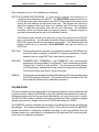
INSTALLATION . . . . . . . . . . . . . . . . . . . . . . . . . . . . . . . . . . . . . . . . . . . . . . . . . . . . . . . . . . . . . . . . . . . .
CD INSTALLATION . . . . . . . . . . . . . . . . . . . . . . . . . . . . . . . . . . . . . . . . . . . . . . . . . . . . . . . . . . .
3.5-INCH DISKETTE INSTALLATION . . . . . . . . . . . . . . . . . . . . . . . . . . . . . . . . . . . . . . . . . . . .
DIRECTORIES CREATED O N THE HARD DISK . . . . . . . . . . . . . . . . . . . . . . . . . . . . . . . . . . .
CALIBRATION . . . . . . . . . . . . . . . . . . . . . . . . . . . . . . . . . . . . . . . . . . . . . . . . . . . . . . . . . . . . . .
HARDWARE INSTALLATION . . . . . . . . . . . . . . . . . . . . . . . . . . . . . . . . . . . . . . . . . . . . . . . . . . .
INPUT/OUTPUT CONNECTIONS . . . . . . . . . . . . . . . . . . . . . . . . . . . . . . . . . . . . . . . . . . . . . . .
50-Pin Connector . . . . . . . . . . . . . . . . . . . . . . . . . . . . . . . . . . . . . . . . . . . . . . . . . . . . . .
GETTING ST ARTED . . . . . . . . . . . . . . . . . . . . . . . . . . . . . . . . . . . . . . . . . . . . . . . . . . . . . . . . .
1-1
1-1
1-1
1-2
1-4
1-5
1-6
1-6
1-8
FUNCTIONAL DESCRIPTION . . . . .
ANALOG INPUTS . . . . . . . .
PROGR AMMABLE OFFSET
ANALOG OUTPUTS . . . . . .
DIG ITA L I/O . . . . . . . . . . . . .
W ATCHDO G TIMER . . . . .
BLOCK DIAGRAM . . . . . . .
2-1
2-2
2-2
2-2
2-2
2-3
2-3
........
........
.......
........
........
........
........
.
.
.
.
.
.
.
.
.
.
.
.
.
.
..........
..........
..........
..........
..........
..........
..........
.
.
.
.
.
.
.
.
.
.
.
.
.
.
..........
..........
..........
..........
..........
..........
..........
.
.
.
.
.
.
.
.
.
.
.
.
.
.
..........
..........
..........
..........
..........
..........
..........
.
.
.
.
.
.
.
.
.
.
.
.
.
.
......
......
......
......
......
......
......
SOFTW ARE . . . . . . . . . . . . . . . . . . . . . . . . . . . . . . . . . . . . . . . . . . . . . . . . . . . . . . . . . . . . . . . . . . . . . . . 3-1
GENERAL . . . . . . . . . . . . . . . . . . . . . . . . . . . . . . . . . . . . . . . . . . . . . . . . . . . . . . . . . . . . . . . . . . 3-1
COMMAND STRUCTURE . . . . . . . . . . . . . . . . . . . . . . . . . . . . . . . . . . . . . . . . . . . . . . . . . . . . . 3-1
Addressed Mode . . . . . . . . . . . . . . . . . . . . . . . . . . . . . . . . . . . . . . . . . . . . . . . . . . . . . . 3-1
Co nce pts: O nbo ard D igital I/O . . . . . . . . . . . . . . . . . . . . . . . . . . . . . . . . . . . . . . . . . . . . 3-1
Concepts: The Point List Buffer . . . . . . . . . . . . . . . . . . . . . . . . . . . . . . . . . . . . . . . . . . . 3-2
RA1216 COMMAND LIST . . . . . . . . . . . . . . . . . . . . . . . . . . . . . . . . . . . . . . . . . . . . . . . . . . . . . . 3-3
COMMAND FUNCTIONS . . . . . . . . . . . . . . . . . . . . . . . . . . . . . . . . . . . . . . . . . . . . . . . . . . . . . . 3-5
Configure Point List . . . . . . . . . . . . . . . . . . . . . . . . . . . . . . . . . . . . . . . . . . . . . . . . . . . . 3-5
Read Point List . . . . . . . . . . . . . . . . . . . . . . . . . . . . . . . . . . . . . . . . . . . . . . . . . . . . . . . . 3-5
W rite Point List to EEPROM . . . . . . . . . . . . . . . . . . . . . . . . . . . . . . . . . . . . . . . . . . . . . 3-5
Restore Point List . . . . . . . . . . . . . . . . . . . . . . . . . . . . . . . . . . . . . . . . . . . . . . . . . . . . . . 3-5
W rite Calibration Param eters . . . . . . . . . . . . . . . . . . . . . . . . . . . . . . . . . . . . . . . . . . . . . 3-5
Return C alibration Param eters . . . . . . . . . . . . . . . . . . . . . . . . . . . . . . . . . . . . . . . . . . . . 3-6
Set Sam ple R ate . . . . . . . . . . . . . . . . . . . . . . . . . . . . . . . . . . . . . . . . . . . . . . . . . . . . . . 3-6
Re ad S am ple R ate . . . . . . . . . . . . . . . . . . . . . . . . . . . . . . . . . . . . . . . . . . . . . . . . . . . . . 3-7
Configure Bits as Input or Output . . . . . . . . . . . . . . . . . . . . . . . . . . . . . . . . . . . . . . . . . . 3-7
Re ad D igital Inputs . . . . . . . . . . . . . . . . . . . . . . . . . . . . . . . . . . . . . . . . . . . . . . . . . . . . . 3-8
W rite Digital Outputs . . . . . . . . . . . . . . . . . . . . . . . . . . . . . . . . . . . . . . . . . . . . . . . . . . . 3-8
Read Firmware Revision Number . . . . . . . . . . . . . . . . . . . . . . . . . . . . . . . . . . . . . . . . . 3-9
Resend Last Response . . . . . . . . . . . . . . . . . . . . . . . . . . . . . . . . . . . . . . . . . . . . . . . . . 3-9
Co nfigure Baud Rate . . . . . . . . . . . . . . . . . . . . . . . . . . . . . . . . . . . . . . . . . . . . . . . . . . 3-10
Configure Pod Address . . . . . . . . . . . . . . . . . . . . . . . . . . . . . . . . . . . . . . . . . . . . . . . . 3-11
Address Select . . . . . . . . . . . . . . . . . . . . . . . . . . . . . . . . . . . . . . . . . . . . . . . . . . . . . . . 3-11
Enter a New Program . . . . . . . . . . . . . . . . . . . . . . . . . . . . . . . . . . . . . . . . . . . . . . . . . . 3-11
SPECIFICATIONS . . . . . . . . . . . . . . . . . . . . . . . . . .
SERIAL COMMUNICATIONS INTERFACE
ANALOG INPUTS . . . . . . . . . . . . . . . . . . . .
DIG ITA L I/O . . . . . . . . . . . . . . . . . . . . . . . . .
POW ER REQUIRED . . . . . . . . . . . . . . . . . .
.
.
.
.
.
.
.
.
.
.
.
.
.
.
.
....
....
....
....
....
.
.
.
.
.
.
.
.
.
.
....
....
....
....
....
.
.
.
.
.
.
.
.
.
.
....
....
....
....
....
.
.
.
.
.
.
.
.
.
.
....
....
....
....
....
.
.
.
.
.
.
.
.
.
.
....
....
....
....
....
.
.
.
.
.
.
.
.
.
.
....
....
....
....
....
.
.
.
.
.
.
.
.
.
.
.
.
.
.
.
4-1
4-1
4-1
4-2
4-2
W ARRANTY . . . . . . . . . . . . . . . . . . . . . . . . . . . . . . . . . . . . . . . . . . . . . . . . . . . . . . . . . . . . . . . . . . . . . . . 5-1
APPLICATION CONSIDERATIONS . . . . . . . . . . . . . . . . . . . . . . . . . . . . . . . . . . . . . . . . . . . . . . . . . . . A-1
ii
REMOTE DAS POD
MODEL RA1216
USER MANUAL
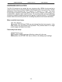
Files contained on the 3.5 inch diskette are as follows:
SETUP & CALIBRATION PROGRAM: A menu-driven program that assists you in
configuring and calibrating your RA1216. The SETUP.EXE program instructs you
on the use of the serial opto-isolation and DAC Offset jumpers and allows you to
specify the Pod Address and the serial baud rate. This program can also autodetect the address and/or baud rate of an attached card in the host computer.
Finally, a calibration procedure tests the unit and determines the calibration
correction values and stores them into internal memory. A sample program is
provided to demonstrate the use of the calibration feature.
The Setup program should be run with only a single Pod attached to the RS-485
port in your computer. You will need to know the setup information (base address,
IRQ) of the port so that the Setup program can access it. The Setup program will
create a batch file in its directory, called RISC.BAT, that can be used to run
RISCTerm.
RISCTerm: This program provides a simple, non-automated interface to RS-485 devices
and can be used to configure or test RA1216 setup and operations. Context
sensitive help on using RISCTerm is provided by pressing .
DRIVERS:
COMMDRV.PAS, COMMDRV.H, and COMMDRV.C are communication
shortcuts or drivers provided in C and Pascal. Three functions are provided:
“initComCard”, “writePod”, and “readPod”. The functions are polling based,
no IRQ necessary, and deal with strings rather than character-by-character.
Consult the source code files for more information.
SAMPLE:
This program demonstrates reading and displaying A/D channels and polling
the Pod for general information. The sample also demonstrates use of the
driver and the software driven calibration procedure.
CALIBRATION
The setup software provided with the RA1216 supports the ability to check calibration and
to write correction values into EEPROM so they are available automatically on power-up.
Calibration checks need only be performed periodically, not every time power is cycled.
The SETUP.EXE software calibration procedure requires the ability to ground an analog
channel and provide a voltage source set at 5.000V and another for 0.250V.
The SAMPLE1 program illustrates the procedure of recalling these values and adjusting
the readings. The command descriptions of CALn? CALn=xxxx,xxxx and CAL=BACKUP
provide instructions on adding the calibration functions to your own software. See the
Software section for a description on calibrating the A/D input and DAC output using the
values from the calibration procedure.
1-1
REMOTE DAS POD
MODEL RA1216
USER MANUAL
HARDWARE INSTALLATION
The RA1216 enclosure is a sealed, die-cast, aluminum-alloy, NEMA-4 enclosure that is
easily mounted using two diagonal holes accessible when the cover is removed. Outside
dimensions of the enclosure are: 8.74" long by 5.75" wide by 2.17" high. The cover
incorporates a recessed neoprene gasket and the cover is secured to the body by six
recessed M-4, stainless steel, captive screws. The mounting holes and cover-attaching
screws are outside the sealed area to prevent ingress of moisture and dust. Four threaded
bosses inside the enclosure provide for mounting the printed circuit board assemblies.
Micro-controller board setup:
JP2, JP3, and JP4:
ISL position TXD, RXD and TXEN are opto-isolated from the host computer. In the
/ISL position the opto-isolators are by-passed. This position allows for a single
power supply and higher baud rates.
Personality board setup:
OFFSET DAC jumper:
OFST position, analog inputs are offset by a value set by the user.
GND position, the OFFSET DAC has no effect on the analog input readings.
1-2
REMOTE DAS POD
MODEL RA1216
USER MANUAL
INPUT/OUTPUT CONNECTIONS
Electrical connections to the RA1216 are through watertight glands that seal the wires
terminated inside to a Euro-style, screw-terminal block that plugs into a 50-pin connector.
To ensure that there is minimum susceptibility to EMI and minimum radiation, it is
important that there be a positive chassis ground. Also, proper EMI cabling techniques
(cable connected to chassis ground, twisted pair wiring, and, in extreme cases, ferrite-level
of EMI protection) may be needed for input/output wiring.
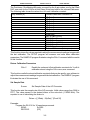
50-Pin Connector
Connector pin assignments for the 50-pin connector are listed below.
Pin
Signal
Pin
Signal
1
3
5
7
9
11
13
15
17
19
21
23
25
27
29
31
RS485 Comm Line (+)
DIO1 Digital I/O Bit 1
DIO3 Digital I/O Bit 3
DIO5 Digital I/O Bit 5
APPLV+ Ext. Dig. Out Power
/PBRST Ext. Reset for µCtrlr
ISOGND Isol. Pwr. Ground
VCC10 10V Pwr. (Ext.Sens.)
PWR+ Local Pwr (+)
AOGND Analog Output Ground
AOUT0 Analog Output 0 (Volt)
AOUT1 Analog Output 1 (Volt)
AOUT2 Analog Output 2 (Volt)
AGND Analog Input Ground
CH00(+) Analog Input Chl 0 (+)
CH00(-) Diff. Analog Input Chl 0(-)
Or S.E. Analog Input Chl 8
AGND Analog Input Ground
CH01(+) Analog Input Chl 1 (+)
CH01(-) Diff. Analog Input Chl 1(-)
Or S.E. Analog Input Chl 9
AGND Analog Input Ground
CH02(+) Analog Input Chl 2 (+)
CH02(-) Diff. Analog Input Chl 2(-)
Or S.E. Analog Input Chl 10
AGND Analog Input Ground
CH03(+) Analog Input Chl 3 (+)
CH03(-) Diff. Analog Input Chl 3(-)
Or S.E. Analog Input Chl 11
2
4
6
8
10
12
14
16
18
20
22
24
26
28
30
32
/RS485 Comm Line (-)
DIO0 Digital I/O Bit 0
DIO2 Digital I/O Bit 2
DIO4 Digital I/O Bit 4
DIO6 Digital I/O Bit 6
ISOV+ Isol. Pwr +
PT0 Input to Counter 0
PINT1 Interrupt 1
GND Digital Pwr Ground
GND Local Pwr. Ground
IOUT0 Analog Output 0 (Current)
IOUT1 Analog Output 1 (Current)
IOUT2 Analog Output 2 (Current)
AGND Analog Output Ground
CH04(+) Analog Input Chl 4 (+)
CH04(-) Diff.Analog Input Chl 4(-)
Or S.E. Analog Input Chl 12
AGND Analog Input Ground
CH05(+) Analog Input Chl 5 (+)
CH05(-) Diff. Analog Input Chl 5(-)
Or S.E. Analog Input Chl 13
AGND Analog Input Ground
CH06(+) Analog Input Chl 6 (+)
CH06(-) Diff. Analog Input Chl 6(-)
Or S.E. Analog Input Chl 14
AGND Analog Input Ground
CH07(+) Analog Input Chl 7 (+)
CH07(-) Diff. Analog Input Chl 7(-)
Or S.E. Analog Input Chl 15
33
35
37
39
41
43
45
47
49
1-3
34
36
38
40
42
44
46
48
50
REMOTE DAS POD
MODEL RA1216
USER MANUAL
Pin Description:
PWR+ and PWR GND:
These terminals are used to apply power to the pod from a
local power supply. The voltage can be anywhere in the range
of 12 VDC to 16 VDC. Higher voltage can be used, 24 VDC
for example, if an external Zener diode is used to reduce the
voltage applied to the RA1216. (See the Specification section
of this manual to determine the Zener diode power rating
required.)
ISOV+ and ISOGND:
This is the power connection for the isolator section that may
be supplied from the computer's +12VDC supply via a pair of
wires on the RS-485 network or from a central power supply.
This power is independent of “local power”. The voltage level
can be from 7.5 VDC to 35 VDC. (An on-board voltage
regulator regulates the power to +5 VDC.) The RA1216
requires only 5mA of current when idling and ~33mA current
when data is being transmitted so any loading effects on the
computer power will be minimal.
.
Note: If separate power is not available, ISOV+ and ISOGND must be
jumpered to the “local power” terminals, which defeats the optical isolation.
RS485+ and RS485-:
These are the terminals for RS-485 serial communications.
CH0-7(+/-) and AGND:
Analog voltage input terminals.
AOUT0-2 and AOGND:
Analog voltage output terminals.
IOUT0-2:
4 to 20mA current output terminals.
DIO0-6:
Digital input or output terminals.
APPLV+:
This terminal is for the “application power” or the user- provided voltage level
to which digital outputs are connected through the loads. Open-collector
Darlington amplifiers are used at the outputs. Inductive suppression diodes
are included in the APPLV circuit. If inductive loads are being driven, this
must be connected. The application power level (APPLV) can be as high as
50 VDC.
1-4
REMOTE DAS POD
MODEL RA1216
USER MANUAL
FUNCTIONAL DESCRIPTION
FEATURES
!
!
!
!
!
!
!
!
Remote Intelligent Analog and Digital I/O Unit with Opto-Isolated RS-485
Serial Interface to Host Computer.
Eight Differential or Sixteen Single-ended Analog Inputs, Programmable
Gain and Offset on a Channel-by-Channel Basis, 12-Bit Resolution A/D
Converter.
Optional Signal Conditioning for Use with Thermocouples, RTDs, 4-20 mA
Current Inputs, and Resistors for Strain Gage Bridge Completion.
Three 12-Bit D/A Converters with Both Voltage and Current Outputs.
Seven Bits of Digital I/O Configured on a Bit-by-Bit Basis as Either Inputs or
High-Current Outputs.
Onboard 16-Bit, 8031 Compatible, Microcontroller with 32K x 8 bits RAM and
32K x 8 bits EEPROM.
All Programming and Calibration in Software, No Switches to Set. Jumpers
available to By-Pass Opto-Isolators if Desired and for Calibration Purposes.
Protective NEMA-4 Enclosure for Harsh Atmospheric and Marine
Environments.
COMPUTER COMMUNICATIONS
A type DS80C310 microcontroller (with 32K x 8 bits SRAM, 32K x 8 bits non-volatile
EEPROM, and a watchdog timer circuit) gives RA1216 the capability and versatility
expected from a modern distributed control system. RA1216 contains CMOS low-power
circuitry, an optically-isolated receiver/transmitter, and power conditioners for local and
external isolated power. The pod can operate at baud rates up to 57.6 K baud and
distances up to 4000 feet with low-attenuation twisted-pair cabling, such as Belden #9841
or equivalent. Data collected by the pod can be stored in local SRAM and accessed later
through the computer's serial port. This facilitates a stand-alone mode of operation.
All programming of RA1216 is in ASCII-based software. ASCII-based programming is
flexible because it permits you to write applications in any high-level language that supports
ASCII string functions. You can use REMOTE ACCES Series pods with virtually any
computer that has an RS-485 port.
The module, or pod, address is programmable from 00 to FF hex. Whatever address is
assigned is stored in EEPROM and used as the default address at the next Power-ON.
Similarly, the baud rate is programmable, is stored in EEPROM, and is used as the default
at the next Power-ON.
2-1
REMOTE DAS POD
MODEL RA1216
USER MANUAL
ANALOG INPUTS
RA1216 uses a 12-bit successive approximation analog-to-digital converter (A/D) capable
of up to 50,000 conversions per second. A/D conversions may be initiated either by
software command or by an external input.
The RA1216 accepts up to sixteen single-ended analog inputs (or eight differential). Solidstate multiplexers are used and, to prevent crosstalk and increase stability between
channels, the input of the multiplexer is shorted to ground before each channel selection
for a time period sufficient to discharge the multiplexer’s output capacitance.
The RA1216 can be configured to accept inputs from a variety of sensor types. The
standard configuration is for voltage inputs. For thermocouple inputs, an on-board
temperature sensor is used to provide input for cold junction compensation, and break
detect resistors are available (specify RA1216T/C). The pod can accept inputs from three
wire RTDs or 4-20 mA transmitter circuits (RA1216R, or RA1216I respectively). It can also
be configured to provide bridge completion in quarter bridge Strain Gage applications
(RA1216B/C).
Eight analog voltage spans and a 4-20 mA current input range are available. All inputs are
internally protected up to 200 VDC. The Programmable Gain Amplifier consists of a
programmable gain instrumentation amplifier and a programmable gain operational
amplifier. This increases the signal conditioning flexibility of the pod.
PROGRAMMABLE OFFSET
Each input can be programmed with an offset of ±2.5Vgenerated by a digital-to-analog
converter. This allows easy scaling and shifting of an input signal to take advantage of the
pod’s full input ranges.
ANALOG OUTPUTS
Three 12-bit digital-to-analog converters provide simultaneous voltage and current outputs.
Voltage outputs are independently programmable in two ranges: 0-5V, and 0-10V.
Simultaneously, each D/A can provide 4-20 mA outputs. These current outputs are derived
for user-supplied compliance voltages from 5.5V to 30V.
DIGITAL I/O
Seven bits of digital I/O are provided. These can be software configured on a bit-by-bit
basis as either inputs or outputs. Digital inputs are sensed at TTL levels. There is one
interrupt input.
Each digital output provides compliance with user-supplied voltages up to 50 VDC and the
maximum sink current per output bit is 350 mA. The maximum total sink current is limited
to 650 mA on all seven bits.
All bits have a factory installed 10K pull up resistor to 5Volts.
2-2
REMOTE DAS POD
MODEL RA1216
USER MANUAL
WATCHDOG TIMER
The built-in watchdog timer resets the pod if the microcontroller “hangs up” or the power
supply voltage drops below 7.5 VDC. The microcontroller can also be reset by an external
manual pushbutton input available at the interface connector.
POWER SUPPLIES
RA1216 requires two power sources to maintain opto-isolation. A small amount of +7.5V
to +24V power (50 mA) is required by the opto-isolated RS485 circuitry, this can be
supplied by the host computer through the cable carrying the RS485 serial data.
Alternatively, you can use an external power supply. The remainder of the RA1216
circuitry is powered by an external power supply of +12V to +16V (500mA).
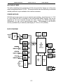
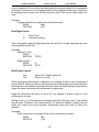
BLOCK DIAGRAM
2-3
REMOTE DAS POD
MODEL RA1216
USER MANUAL
SOFTWARE
GENERAL
The RA1216 comes with ASCII-based software provided on CD or diskette. ASCII
programming permits you to write applications in any high-level language that supports
ASCII text string functions. This allows REMOTE ACCES series modules to be used with
virtually any computer that has an RS-485 port.
The communication protocol has two forms: addressed and non-addressed. Nonaddressed protocol is used when there is only one REMOTE ACCES pod. Addressed
protocol must be used when there is more than one REMOTE ACCES pod. The difference
is that an address command is sent to enable the specific pod. The address command is
only sent once during communication between the specific pod and the host computer. It
enables communication with that specific pod and disables all other REMOTE ACCES
devices from communicating on the network.
COMMAND STRUCTURE
All communication must be 7 data bits, even parity, 1 stop bit. All numbers sent to and
received from the pod are in hexadecimal form. The factory default baud rate is 9600
Baud. The pod is considered to be in addressed mode any time its pod address is not 00.
The factory default pod address is 00 (non-addressed mode).
Addressed Mode
The address select command must be issued before any other command to the addressed
pod. The address command is as follows:
“!xx[CR]”
where xx is the pod address from 01 to FF hex, and [CR] is Carriage
Return, ASCII character 13.
The pod responds with “[CR]”. Once the address select command has been issued, all
further commands (other than a new address select) will be executed by the selected pod.
The addressed mode is required when using more than one pod. When there’s only one
pod connected, no address select command is needed.
Pod commands are listed in the following table. Terminology used is as follows:
a.
b.
c.
d.
e.
The single lower case letter ‘x’ designates any valid hex digit (0-F).
The symbol ‘±’ designates either a ‘+’ or a ‘-’.
All commands are terminated with [CR], the ASCII character 13.
All commands are not case-sensitive, i.e., upper or lower case may be used.
The symbol ‘*’ means zero or more valid characters (total msg length < 255
decimal)
Concepts: Onboard Digital I/O
3-1
REMOTE DAS POD
MODEL RA1216
USER MANUAL
The RA1216 has 7 digital inputs/outputs. The outputs are on the same pins as the
inputs.They comprise the DI/O port.
Concepts: The Point
unused
use 0s
D0
D1
D2
D3
D4
D5
D6
D7
D8
D9
D10
D11
D12
D13
D17
D18
D19
CHANNEL
D16
Diff/SE D15
D14
GAIN
D20
D21
D22
CAL D23
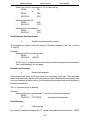
A Point, as used in the RA1216, is a channel number and its associated gain,
Diff/SE, and offset settings. The Point defines the A/D channel number, what gain
should be applied, whether it is single-ended or differential, and what setting is
desired on the Offset DAC. The format of the 3-byte Point is as follows:
Offset DAC count value
A typical Point might be 308800, which would translate to gain code 3, channel 0,
single ended, with zero volts on the Offset DAC (see the Offset DAC section for
more info).
GAIN
CODE
0
1
2
3
4
5
6
7
GAIN BASE A/D RANGE
Volts
1
0-5
2
0 - 2.5
5
0 - 1.0
10
0 - 0.5
20
0 - 0.25
40
0 - 0.125
100
0 - 0.05
200
0 - 0.025
The “BASE A/D RANGE” column indicates the input range associated with each
gain code, assuming the offset DAC voltage is zero. The offset DAC will shift this
base range by the amount of voltage supplied.
Concepts: The Point List Buffer
Because each channel can be acquired at a different gain and Offset DAC setting,
some setup is necessary to improve usability. The setup consists of telling the Pod
the input range and Diff/SE for each channel and the order in which to acquire the
channels. This is done using the Point List (PL) series of commands. The Point List
is a list of the channels to be acquired, along with all of the configuration information
for each channel. All of the commands to set PL entries take a point number (or the
keyphrase “ALL”), and a 3-byte (6 hex digit) value describing the configuration for
that point (or the keyphrase “DEFAULT”).
ALL numbers passed to and from the Pod are in hexadecimal.
3-2
REMOTE DAS POD
MODEL RA1216
USER MANUAL
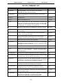
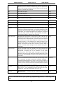
RA1216 COMMAND LIST
Com mand
Description
Returns
PROGRAM=
Use with caution. Loads new firm ware into the Pod's
EEPR OM . Use ES C (A SC II 27) to abo rt.
n/a
| (Vertical Bar)
Sa m e as P ROGRAM =, except us ed only after a re set to g ain
access to Pod.
n/a
BAUD=nnn
Sets Ba ud ra te
=:Baud:0n
POD=xx
Sets the Pod address to xx
=:Pod#xx
S=xxxx
Sets the Sample Rate of the A/D. Valid ranges are 00A2 through
FFFF. Value passed is the desired divisor of the rate clock. 00A2
is 666 6H z, or 150us /sam ple. 039A is 1000Hz, or 1ms/sample.
(11,059,200Hz / 12 / timebase = Hz sam ple rate.
[CR]
S?
Returns the Clock Divisor from EEPRO M on the Pod, as above.
xxxx[CR]
!xx
Address Select Comm and, Selects the Pod at address 'xx' for
comm unication.
[CR]
H*
“Hello” comm and. H followed by anything returns Pod name,
revision, and copyright message.
See Desc.
N
Resend last message. Causes the Pod to re-transmit last
message. Should be used upon parity-error, for example.
See Desc.
V
Reads the version number from the firmware.
x.xx[CR]
PLnn=xxxxxx
Set Point List Entry fo r point num ber n n to xxxxxx. See Concepts:
The Point for more information on the point configuration setup
required to use the PL comm ands.
[CR]
PLnn?
Reads the Point List entry for point number nn.
XXXXXX[CR]
PLALL?
Reads the Point Configuratio n fo r all p oints (0-40 hex). Data is
returned as XXXXX X XXX XXX ... XXXXX X XXX XXX [CR] with a
total of 64 entries.
See Desc.
PLnn=DEFAULT
Sets point nn to default configuration (5V span, no o ffset, S.E.)
[CR]
PLALL=DEFAU LT
Sets all points to default con figura tion (5V spa n, entries 0-F=A/D
channel 0-F S.E., all other entries= AD channel 0)
[CR]
BACKUP=PL
Stores the point list into the onbo ard EEP RO M, for powe r-off
safekeeping. The point list is restored autom atically every time the
Pod is reset, or using the PLALL=BACKUP com mand.
[CR]
PLALL=BACKUP
Restores the EE PR OM point list into the current point list. This
com m and is exe cute d au tom atically upo n Po d res et.
[CR]
CALn=xxxx,xxxx
W rites offset and scale calibration constants #n used for
Y=MX+B calibration. Used by setup/calibration procedures.
[CR]
CALn?
Returns stored calibration constant # n. See sample program on
disk for example usage.
xxxx,xxxx
[CR]
CAL=BACKUP
Use this comm and to restore the factory calibration, overwriting
the current user calibration. The factory cal is stored
permanently in EEPROM during the initial calibration.
[CR]
3-3
REMOTE DAS POD
MODEL RA1216
USER MANUAL
Mxx
Set bits as Inputs or Outputs. Each bit of xx controls a single bit of
the DIO port. One’s set the corresponding port as output, zeroes
set the port as input. W riting to a port m arke d as input will fail.
Power-on default is ALL INPUTS.
[CR]
Mx+
Tu rns bit x to ou tput.
[CR]
Mx-
Tu rns bit x to input.
[CR]
Oxx
W rites xx to the DI/O port.
[CR]
Ox+
Sets output bit x (0-6) to ONE.
[CR]
Ox-
Sets output bit x to ZERO.
[CR]
I
Th is com m and read s the seven d igital inputs
xx[CR]
In
Single-bit read from bit 0-6.
0[CR] or
1[CR]
Axxxxxx
Acquires a single channel and returns the data imm ediately via the
serial port, bypassing the point list. This comm and takes as its sole
argument the same 3-byte parameter passed to the PL series of
comm ands. The channel specified in the param eter is acquired
using the ran ge, polarity, an d M UX gain specified. The data is
returned imm ediately, unlike the AC com mand.
XXXX[CR]
ACnn 1-nn 2,xxxx
Acquires point list entries nn 1 through nn2, with a total of xxxx
conversions performed. xxxx m ust be equal to or less than
2710hex (which is 10000 decimal--all numbers must be presented
to the Pod in hex). 10000 data samples is the maximum internal
storage capacity of the standard Pod. (Optional firmw are can
increase this capacity. Contact the factory for further inform ation.)
Please note th at th is fu nction does not return any data . Data is
stored in internal SR AM sto rage for later retrieval using the R
comm and.
[CR]
Ann 1-nn 2,xxxx
The A com m and wo rks very sim ilarly to the AC com m and. A ll
param eters are the same. However, the A comm and runs in the
foreground, occupying all of the attentio n of the Pod’s
m icrocontroller. This yields higher throughput, but sacrifices
flexibility. The Pod acq uires data at its fas test poss ible rate. Data
is sto red in internal SRA M stora ge for later retrieval using the R
comm and.
[CR]
R*
This comm and reads the last buffer of data acquired using the AC
or A co m m and . The da ta is retu rned in CC XX XX CC XX XX ...
CCXXXX CC XX XX [CR] form at, where CC is the point number that
was acquired, and XXXX is the analog conversion data. The total
number of return values is identical to the XXXX parameter passed
to the most recently issued AC com mand.
see desc.
An=mxxx
Set analog output n to xxxx, with 0-5V range if m is 0, or 0-10V
range if m is 1. xx x is hexadecim al counts ; 000 is 0V, FF F is full
scale(5V or 10V), 800 is half scale(2.5V or 5V), etc.
[CR]
AA=m xxx
Sim ilar to the A n= c om m and , but sets all three analog ou tputs to
the same value.
[CR]
NOTE: Pod reset occurs upon power-up, programming process, or watchdog timeout.
3-4
REMOTE DAS POD
MODEL RA1216
USER MANUAL
COMMAND FUNCTIONS
The following paragraphs give details of the command functions, describe what the
commands cause, and give examples. Please note that all commands have an
acknowledgment response. You must wait for a response from a command before sending
another command.
Configure Point List
PLnn=xxxxxx
Sets point list entry for point number nn to xxxxxx.
PLnn=DEFAULT Sets point nn to default configuration.
PLALL=DEFAULT Sets all points to default configuration.
NOTE: Default configuration is 0-5V Single Ended.
Read Point List
PLnn?
PLALL?
Reads the point configuration for point number nn.
Reads the point configuration for all points (0-127).
NOTE: Data is returned as xxxxxx xxxxxx... xxxxxx[CR] with a total of 64 entries.
Write Point List to EEPROM
BACKUP=PL
Stores the point list configuration in the onboard
EEPROM, for power-off safekeeping.
NOTE: The point list configuration is automatically restored every time the Pod is
reset, or when PLALL=BACKUP command is issued.
Restore Point List
PLALL=BACKUP
Restores point list configuration in EEPROM to the
current point list.
NOTE: This command is executed automatically upon Pod reset.
Write Calibration Parameters
CALn= bbbb,aaaa Write offset and scale calibration values for Y=mX+b
calibration in two’s-complement hex as two four-digit
numbers. The full equation for calibrated input to the
A/D is Y=(4095/(4095-a-b))X-b. The equation for
calibrated DAC output is Y=((4095-a-b)/4095)X+b. In
both equations, b is the number of counts below zero
and a is the number of counts over full scale. CAL
entries 0-7 use the A/D equation. Entries 9-14 use the
DAC equation.
3-5
REMOTE DAS POD
MODEL RA1216
USER MANUAL
The Pod stores 16 calibration M/b pairs, one each for the 8 gain codes, one for the Offset
DAC, one each for the 3 DACs at both Gains (6 total) and one for the onboard Reference.
The following table shows the values for n for each calibration constant:
Entry number (n)
0
1
2
3
4
5
6
7
8
9
10
11
12
13
14
15
Contains calibration constants for:
AD Gain 0
AD Gain 1
AD Gain 2
AD Gain 3
AD Gain 4
AD Gain 5
AD Gain 6
AD Gain 7
Offset DAC
DAC 0 Gain 0 (0-5V)
DAC 1 Gain 0
DAC 2 Gain 0
DAC 0 Gain 1 (0-10V)
DAC 1 Gain 1
DAC 2 Gain 1
Onboard Reference (factory use)
This function stores the values required to adjust the measurement readings to agree with
the last calibration. The SETUP program will measure and write these calibration
parameters. The SAMPLE1 program illustrates using the CALn? command with the results
of this function.
Return Calibration Parameters
CALn?
Recalls the scale and offset calibration constants for Y=mX+b
calibration stored using the CALn=xxxx,xxxx command.
This function recalls the stored calibration constants that may be used by your software to
adjust the measurement readings to agree with the last calibration. The SAMPLE1 program
illustrates the use of this command.
Set Sample Rate
S=xxxx
Set Sample Rate of the A/D Converter
This function sets the sample rate of the A/D converter. Valid values range from 00A2 to
FFFF. The value passed is the desired divisor of the rate clock (11.0592 MHz). The
equation to use in calculating the divisor is:
Divisor = [(1/Rate) - 22µSec] * [Clock/12]
Examples:
Program the RA1216 for 1K samples per second.
SEND:
S=0385
RECEIVE:
[CR]
3-6
REMOTE DAS POD
MODEL RA1216
USER MANUAL
NOTE: The sample rate configured is stored in EEPROM on the Pod and will be
used as the default (power-on) sample rate. The factory default sample rate
(100Hz) can be restored by sending "S0000" to the Pod.
Read Sample Rate
S?
Returns the clock Divisor from EEPROM on the Pod.
Special Acquisition Commands
ACnn1-nn2,xxxx:
Acquires Point List entries nn1 through nn2, with a total
of xxxx conversions performed.
xxxx must be equal to or less than 2710hex (which is 10000 decimal--all numbers must be
presented to the Pod in hex). 10000 data samples is the maximum internal storage
capacity of the standard Pod. (Optional firmware can increase this capacity. Contact the
factory for further information.) Please note that this function does not return any data.
Data is stored in the internal SRAM storage for later retrieval using the R command.
R:
This command reads the last buffer of data acquired using the AC
command.
The data is returned in CCXXXX CCXXXX ... CCXXXX CCXXXX[CR] format, where CC
is the point number that was acquired, and XXXX is the analog conversion data. The total
number of return values is identical to the XXXX parameter passed to the most recently
issued AC command.
Axxxxxx:
Acquires a single channel and returns the data immediately via
the serial port, bypassing the point list.
This command takes as its sole argument the same 3-byte parameter passed to the PL
series of commands. The channel specified in the parameter is acquired using the range,
polarity, and MUX gain specified. The data is returned immediately, unlike the AC
command.
Ann1-nn2,xxxx
The A command works very similarly to the AC
command. All parameters are the same. However, the
A command runs in the foreground, occupying all of the
attention of the Pod’s microcontroller. This yields higher
throughput, but sacrifices flexibility. The Pod acquires
data at its fastest possible rate. Issue an R command to
retrieve the data.
Configure Bits as Input or Output
Mxx
Mx+
Mx-
Configures digital bits as inputs or outputs.
Configures digital bit 'x' as output.
Configures digital bit 'x' as input.
These commands program the digital bits, on a bit-by-bit basis, as input or output. A “zero”
3-7
REMOTE DAS POD
MODEL RA1216
USER MANUAL
in any bit position of the xx control byte designates the corresponding bit to be configured
as an input. Conversely, a “one” designates a bit to be configured as an output. (Note: Any
bit configured as an output can still be read as an input if the current value output is a
“one”.
Example:
Program even bits as outputs, and odd bits as inputs.
SEND:
MAA
RECEIVE:
[CR]
Read Digital Inputs
I
In
Read 7 bits.
Read bit number n.
These commands read the digital input bits from the Pod. All byte responses are sent
most-significant nybble first.
Examples:
Read ALL 7 bits.
SEND:
RECEIVE:
Read only bit 2.
SEND:
RECEIVE:
I
FF[CR]
I2
1[CR]
Write Digital Outputs
Oxx
Ox±
Write to all 7 digital output bits.
Set bit x hi or low.
These commands write outputs to digital bits. Any attempt to write to a bit configured as
an input will fail. Writing to a byte or word wherein some bits are input and some are output
will cause the output latches to change to the new value, but the bits that are inputs will not
output the value until/unless they are placed in output mode.
Single bit commands will return an error (4) if an attempt is made to write to a bit
configured as an input.
Writing a “one” (+) to a bit asserts the pull-down for that bit. Writing a “zero” (-) de-asserts
the pull-down. Therefore, if the factory default +5V pull-up is installed, writing a one will
cause zero volts to be at the connector, and writing a zero will cause +5 volts to be
asserted.
Examples:
Write a one to bit 6 (set output to zero volts, assert the pull-down).
SEND:
O6+
RECEIVE:
[CR]
3-8
REMOTE DAS POD
MODEL RA1216
USER MANUAL
Write a zero to bit 2 (set output to +5V or user pull-up).
SEND:
O2or
SEND:
O02RECEIVE:
[CR]
Write zeros to bits 0-6.
SEND:
RECEIVE:
O00
[CR]
Write zeros to every odd bit.
SEND:
OAA
RECEIVE:
[CR]
Read Firmware Revision Number
V
Read the firmware revision number.
This command is used to read the version of firmware installed in the Pod. It returns
“X.XX[CR]”.
Example:
Read the RA1216 version number.
SEND:
V
RECEIVE: 1.00[CR]
NOTE: The “H” command returns the version number along with other information.
See “Hello Message” on next page.
Resend Last Response
n
Resend last response
This command will cause the Pod to return the same thing it just sent. This command
works for all responses less than 255 characters in length. Normally this command is used
if the host detected a parity or other line fault while receiving data and needs the data to
be sent a second time.
The “n” command may be repeated.
Example:
Assuming the last command was “I”, ask Pod to resend last response.
SEND:
n
RECEIVE: FFFFFF[CR]
;or whatever the data was
Hello Message
H*
Hello message
Any string of characters starting with “H” will be interpreted as this command. (“H[CR]”
3-9
REMOTE DAS POD
MODEL RA1216
USER MANUAL
alone is also acceptable.) The return from this command takes the form (without the
quotes):
“=Pod aa, RA1216 Rev rr Firmware Ver:x.xx ACCES I/O Products, Inc.”
aa is the Pod address
rr is the hardware revision, such as “B1"
x.xx is the software revision, such as “1.00"
Example:
Read the greeting message.
SEND:
Hello?
RECEIVE: =
Pod 00, RA1216 Rev B1 Firmware Ver:1.00 ACCES I/O
Products, Inc.[CR]
Configure Baud Rate (When initially shipped, the baud rate is set at 9600.)
BAUD=nnn Program the Pod with a new baud rate
This command sets the Pod to communicate at a new baud rate. The parameter passed,
nnn, is slightly unusual. Each n is the same digit from the following table:
CODE
0
1
2
3
4
5
6
7
BAUD RATE
1200
2400
4800
9600
14400
19200
28800
57600
Therefore, valid values for the command’s “nnn” are 000, 111, 222, 333, 444, 555, 666,
or 777.The pod returns a message indicating it will comply. The message is sent in the old
baud rate, not the new one. Once the message is transmitted, the Pod changes to the new
baud rate. The new baud rate is stored in EEPROM and will be used even after powerreset, until the next “BAUD=nnn” command is issued.
Examples:
Set the Pod to 19200 baud.
SEND:
BAUD=555
RECEIVE:
=:Baud:05[CR]
Set the Pod to 9600 baud.
SEND:
BAUD=333
RECEIVE:
=:Baud:03[CR]
3-10
REMOTE DAS POD
MODEL RA1216
USER MANUAL
Configure Pod Address
POD=xx
Program the currently selected Pod to respond at address xx.
This command changes the Pod’s address to xx. If the new address is 00, the Pod will be
placed into non-addressed mode. If the new address is not 00, the Pod will not respond
to further communications until a valid address command is issued. Hex numbers 00-FF
are considered valid addresses. The RS-485 specification allows only 32 drops on the line,
so some addresses may be unused.
The new Pod address is saved in EEPROM and will be used even after power-down until
the next “Pod=xx” command is issued. Note that, if the new address is not 00 (i.e., the Pod
is configured to be in addressed mode), it is necessary to issue an address command to
the Pod at the new address before it will respond.
The Pod returns a message containing the Pod number as confirmation.
Examples:
Set the Pod address to 01.
SEND:
A=01
RECEIVE:
=:Pod#01[CR]
Set the Pod address to F3.
SEND:
A=F3
RECEIVE:
=:Pod#F3[CR]
Take the Pod out of addressed mode.
SEND:
A=00
RECEIVE:
=:Pod#00[CR]
Address Select
!xx
Selects the Pod addressed 'xx'
NOTE: When using more than one Pod in a system, each Pod is configured with a unique
address. This command must be issued prior to any other commands to that particular
Pod. This command needs to be issued only once prior to executing any other commands.
Once the address select command has been issued, that Pod will respond to all other
commands until a new address select command is issued.
Enter a New Program
PROGRAM= This command initiates transfer of a new program to the RA1216.
This command should be used carefully. If you accidentally issue a “PROGRAM=”
command, ESC (ASCII 27) will restart the Pod as if power had been reset. This feature is
designed to allow ACCES to provide field-upgrades to the RA1216 firmware, and, for
advanced users, the opportunity to customize the firmware in the Pod. Documentation on
using this command is provided with the upgrade diskette, or is available separately for a
small fee.
3-11
REMOTE DAS POD
MODEL RA1216
USER MANUAL
| (Vertical Bar)= Same as PROGRAM= except it is used only after a reset has
occurred. Allows access to Pod to download new firmware.
ERROR CODES
The following error codes can be returned from the Pod:
1:
3:
4:
9:
Invalid channel number (too large, or not a number. All channel numbers
must be between 00 and 0F, in hex).
Improper Syntax. (Not enough parameters is the usual culprit).
Channel number is invalid for this task (For example if you try to output to a
bit that is set as an input bit, that will cause this error).
Parity error. (This occurs when some part of the received data contains a
parity or framing error).
Additionally, several full-text error codes are returned. All begin with “Error, ” and are useful
when using a terminal to program the Pod.
Error, Unrecognized Command: {command received}[CR]
This occurs if the command is not recognized.
Error, Command not fully recognized: {Command received}[CR]
This occurs if the first letter of the command is valid, but the remaining letters
are not.
Error, Address command must be CR terminated[CR]
This occurs if the address command (!xx[CR]) has extra characters between
the Pod number and the [CR].
3-12
REMOTE DAS POD
MODEL RA1216
USER MANUAL
SPECIFICATIONS
SERIAL COMMUNICATIONS INTERFACE
Serial Port:
Opto-isolated Matlabs type LTC485 Transmitter/Receiver. Compatible with
RS-485 specification. Up to 32 drivers and receivers allowed on the line. I/O
bus programmable from 00 to FF hex (0 to 255 decimal). Whatever address
is assigned is stored in EEPROM and used as default at next Power-On.
Asynchronous Data Format: 7 data bits, even parity, one stop bit
Input Common Mode Voltage: 300V minimum (opto-isolated). If opto-isolators are bypassed: -7V to +12V.
Receiver Input Sensitivity: ±200 mV, differential input.
Receiver Input Impedance: 12KW minimum
Transmitter Output Drive: 60 mA, 100 mA short circuit current capability.
Serial Data Rates: Programmable for 1200, 2400, 4800, 9600, 14400, 19200, 28800, and
57600 baud. Crystal oscillator provided.
ANALOG INPUTS
Channels: Sixteen single-ended with common ground or eight differential.
Voltage Ranges: Software controllable.
Unipolar: 0-5V, 0-2.5V, 0-1V, 0-500 mV, 0-250 mV, 0-125 mV,
0-50 mV, and 0-25 mV.
Bipolar: ±2.5V, ±1.25V, ±500 mV, ±250 mV, ±62.5 mV, ±25 mV,
and ±12.5 mV.
Current Range: 4-20 mA across 200S (0.8 - 4V).
Input Protection: 200 VDC.
Input Filter: Low-pass (10KS/0.1µF).
Input Impedance: 10 Megohms.
Resolution: 12 binary bits.
Accuracy: 0.025% ±1 LSB.
Gain Drift: ±5 PPM/ºC
Coding:True binary for unipolar inputs and offset binary for bipolar inputs.
Throughput: 50,000 conversions per second in foreground mode, 6.67K conversions per
second in background mode.
A/D Type: Successive Approximation
Trigger Source: Software command or on-board programmable timer.
ANALOG OUTPUTS
Channels:
Type:
Non-Linearity:
Monotonicity:
Output Range:
Current Output:
Output Drive:
Output Resistance:
Settling Time:
Three independent.
12-bit, double-buffered
±0.9 LSB maximum.
±½ bit.
0-5V, 0-10V.
4-20 mA (User supplied excitation of 5.5V-30V).
5 mA.
0.5 S.
15 µsec to ±½ LSB.
4-1
REMOTE DAS POD
MODEL RA1216
USER MANUAL
DIGITAL I/O
Seven bits configured as input or output
Digital Inputs
Digital Outputs
Logic High: +2.0V to +50V at 20µA max. (5mA max at 50V in)
Protected to 200 VDC
Logic Low: -30V to +0.8V at -0.4 mA max. Protected to -140
VDC.
Logic-Low Sink Current: 350 mA maximum. (See note below.)
Inductive kick suppression diode included in the each circuit.
NOTE
Maximum allowable current per output bit is 350 mA. When all
seven bits are used, there is a maximum total current of 650 mA.
High-Level Output Voltage: Open Collector, compliance with up to
50VDC user-supplied voltage. If no user supplied voltage exists,
outputs pulled up to +5VDC via 10 kS resistors.
INTERRUPT INPUT (For use with development kit)
Input Low: -0.3V to +0.8V.
Input Low Current at 0.45V: -55 µA.
Input High: 2.0V to 5.0V
POWER REQUIRED
Power can be applied from the computer's +12VDC power supply for the opto-isolated
section via the serial communication cable and from a local power supply for the rest of the
unit. If you do not wish to use power from the computer, a central power supply may be
used for the opto-isolated section.
Local Power: 12 to 16 VDC @ 500 mA. (See box that follows.)
Opto-Isolated Section:7.5 to 24 VDC @ 50 mA. (Note: Due to the small amount of current
required, voltage drop in long cables is not significant.)
If the local power supply has an output voltage greater than
16VDC, you can install a Zener diode in series with the supply
voltage. The voltage rating of the Zener diode (V Z) should be
equal to VI - 16 where VI is the power supply voltage. The power
rating of the Zener diode should be $ VZ x 0.35 (watts). Thus, for
example, a 24VDC power supply would require using an 8.2V
Zener diode with a power rating of 8.2 x 0.35 . 3 watt.
4-2
REMOTE DAS POD
MODEL RA1216
USER MANUAL
WARRANTY
Prior to shipment, ACCES products are thoroughly inspected and tested to applicable
specifications. However, should equipment failure occur, ACCES assures its customers
that prompt service and support will be available. All equipment originally manufactured by
ACCES which is found to be defective will be repaired or replaced subject to the following
considerations.
TERMS AND CONDITIONS
If a unit is suspected of failure, contact ACCES' Customer Service department. Be
prepared to give the model number, serial number, and a description of the failure
symptom(s). We may suggest some simple tests to confirm the failure. We will assign a
Return Material Authorization (RMA) number which must appear on the outer label of the
return package. All units/components should be properly packed for handling and returned,
freight prepaid, to the ACCES designated Service Center, and will be returned to the
customer's/user's site freight prepaid and invoiced.
COVERAGE
First Three Years: Returned unit/part will be repaired and/or replaced at ACCES option
with no charge for labor or parts not excluded by warranty. Warranty commences with
equipment shipment.
Following Years: Throughout your equipment's lifetime, ACCES stands ready to provide
on-site or in-plant service at reasonable rates similar to those of other manufacturers in the
industry.
EQUIPMENT NOT MANUFACTURED BY ACCES
Equipment provided but not manufactured by ACCES is warranted and will be repaired
according to the terms and conditions of the respective equipment manufacturer's
warranty.
GENERAL
Under this Warranty, liability of ACCES is limited to replacing, repairing or issuing credit
(at ACCES discretion) for any products which are proved to be defective during the
warranty period. In no case is ACCES liable for consequential or special damage arising
from use or misuse of our product. The customer is responsible for all charges caused by
modifications or additions to ACCES equipment not approved in writing by ACCES or, if
in ACCES opinion the equipment has been subjected to abnormal use. "Abnormal use" for
purposes of this warranty is defined as any use to which the equipment is exposed other
than that use specified or intended as evidenced by purchase or sales representation.
Other than the above, no other warranty, expressed or implied, shall apply to any and all
such equipment sold or furnished by ACCES.
5-1
REMOTE DAS POD
MODEL RA1216
USER MANUAL
APPENDIX A
APPLICATION CONSIDERATIONS
INTRODUCTION
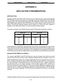
Working with RS-422 and RS-485 devices is not much different from working with standard
RS-232 serial devices and these two standards overcome deficiencies in the RS-232
standard. First, the cable length between two RS-232 devices must be short; less than 50
feet at 9600 baud. Second, many RS-232 errors are the result of noise induced on the
cables. The RS-422 standard permits cable lengths up to 4000 feet and, because it
operates in the differential mode, it is more immune to induced noise.
Connections between two RS-422 devices (with CTS ignored) should be as follows:
Device #1
Device #2
Signal
Pin No.
Signal
Pin No.
Gnd
TX+
TXRX+
RX-
5
2
3
9
1
Gnd
RX+
RXTX+
TX-
5
9
1
2
3
A third deficiency of RS-232 is that more than two devices cannot share the same cable.
This is also true for RS-422 but RS-485 offers all the benefits of RS-422 plus allows up to
32 devices to share the same twisted pairs. An exception to the foregoing is that multiple
RS-422 devices can share a single cable if only one will talk and the others will all receive.
BALANCED DIFFERENTIAL SIGNALS
The reason that RS-422 and RS-485 devices can drive longer lines with more noise
immunity than RS-232 devices is that a balanced differential drive method is used. In a
balanced differential system, the voltage produced by the driver appears across a pair of
wires. A balanced line driver will produce a differential voltage from ±2 to ±6 volts across
its output terminals. A balanced line driver can also have an input “enable” signal that
connects the driver to its output terminals. If the “enable signal is OFF, the driver is
disconnected from the transmission line. This disconnected or disabled condition is usually
referred to as the “tristate” condition and represents a high impedance. RS-485 drivers
must have this control capability. RS-422 drivers may have this control but it is not always
required.
A balanced differential line receiver senses the voltage state of the transmission line across
A-1
REMOTE DAS POD
MODEL RA1216
USER MANUAL
the two signal input lines. If the differential input voltage is greater than +200 mV, the
receiver will provide a specific logic state on its output. If the differential voltage input is
less than -200 mV, the receiver will provide the opposite logic state on its output. A
maximum operating voltage range is from +6V to -6V allows for voltage attenuation that
can occur on long transmission cables.
A maximum common mode voltage rating of ±7V provides good noise immunity from
voltages induced on the twisted pair lines. The signal ground line connection is necessary
in order to keep the common mode voltage within that range. The circuit may operate
without the ground connection but may not be reliable.
RS-422 SPECIFICATION SUMMARY
Parameter
Conditions
Driver Output Voltage
(unloaded)
Driver Output Voltage (loaded)
LD and LDGND
jumpers in
Min.
Max.
4V
-4V
6V
-6V
2V
-2V
Driver Output Resistance
50W
Driver Output Short-Circuit
Current
±150 mA
Driver Output Rise Time
10% unit interval
Receiver Sensitivity
±200 mV
Receiver Common Mode
Voltage Range
±7V
Receiver Input Resistance
4KW
To prevent signal reflections in the cable and to improve noise rejection in both the RS-422
and RS-485 mode, the receiver end of the cable should be terminated with a resistance
equal to the characteristic impedance of the cable. (An exception to this is the case where
the line is driven by an RS-422 driver that is never “tri-stated” or disconnected from the line.
In this case, the driver provides a low internal impedance that terminates the line at that
end.)
A-2
REMOTE DAS POD
MODEL RA1216
USER MANUAL
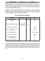
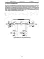
RS-485 DATA TRANSMISSION
The RS-485 Standard allows a balanced transmission line to be shared in a party-line
mode. As many as 32 driver/receiver pairs can share a two-wire party line network. Many
characteristics of the drivers and receivers are the same as in the RS-422 Standard. One
difference is that the common mode voltage limit is extended and is +12V to -7V. Since any
driver can be disconnected (or tri-stated) from the line, it must withstand this common
mode voltage range while in the tristate condition.
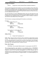
The following illustration shows a typical multidrop or party line network. Note that the
transmission line is terminated on both ends of the line but not at drop points in the middle
of the line.
Typical RS-485 Two-Wire Multidrop Network
A-3