1
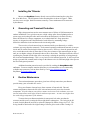
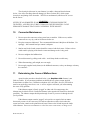
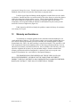
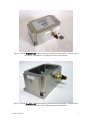
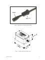
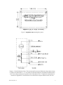
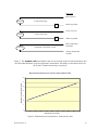
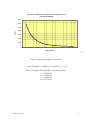
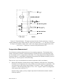
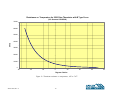
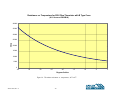
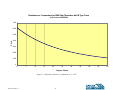
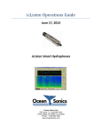
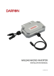
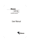
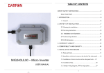
User’s Manual DeepWater 420 Submersible Tiltmeters With 4-20 mA Output Serial No.________________ Standard (±3° range), uniaxial, transverse configuration Standard (±3° range), uniaxial, longitudinal configuration Standard (±3° range), biaxial Wide-angle (±50° range), uniaxial, transverse configuration Wide-angle (±50° range), uniaxial, longitudinal configuration Wide-angle (±50° range), biaxial 140 Chestnut Street San Francisco, CA 94111 Phone: 415–364–3200 Fax: 415–861–1448 www.geomechanics.com Tel (831) 462-2801, Fax (831) 462-4418 e-mail: [email protected] www.geomechanics.com WARNING! NEVER USE AN OHMMETER TO MEASURE THE TILT SENSORS INSIDE THE TILTMETER. APPLYING DC CURRENT THROUGH THE SENSORS WILL CAUSE PERMANENT DAMAGE THAT IS NOT COVERED BY THE WARRANTY. Copyright ©2006 by Applied Geomechanics Inc. All rights reserved. Manual No. B-06-1004, Rev. A. Printed in USA. TABLE OF CONTENTS 1 Introduction .............................................................................................................................................. 1 2 Technical Highlights ................................................................................................................................ 1 3 Specifications ........................................................................................................................................... 2 4 Dimensions and Tilt Polarity .................................................................................................................. 2 5 Measuring Tilt (Rotation)......................................................................................................................... 3 6 Measuring Temperature .......................................................................................................................... 3 7 Installing the Tiltmeter............................................................................................................................. 4 8 Grounding and Transient Protection ..................................................................................................... 4 9 Routine Maintenance ............................................................................................................................... 4 10 Connector Maintenance .......................................................................................................................... 5 11 Determining the Cause of Malfunctions ................................................................................................ 5 12 Warranty and Assistance ........................................................................................................................ 6 Appendix A Connectors, Wiring, Angle Conversion Chart ................................................................... 13 Appendix B Measuring Temperature with 4-20 mA Tiltmeters and Clinometers ................................ 15 Appendix C Calibration Certificates ........................................................................................................ 22 1 Introduction The DeepWater 420 is a precision tiltmeter (inclinometer) designed for underwater measurements and other applications involving high external pressures (Figure 1). It offers durability, unrivaled sensitivity and long-term stability under these demanding conditions. DeepWater tiltmeters are an excellent choice for monitoring the behavior of underwater structures, such as dams, oil platforms and pipelines; measuring the rotational movement of dredges and other underwater machinery; and tracking the pitch and roll of ships and other vessels. 2 Technical Highlights Your DeepWater 420 tiltmeter senses angular movement (rotation) with respect to the vertical gravity vector. The internal transducer is an electrolytic tilt sensor, similar to a spirit level. As the sensor tilts, internal electrodes are covered or uncovered by a conductive fluid, producing changes in electrical resistance when an AC excitation passes through the sensor. The changes are measured using an AC voltage divider network. The resulting signals are amplified, actively rectified, filtered and then converted to form a 4-20 mA current that is proportional to the measured angular rotation, or tilt. The uniaxial version of the tiltmeter contains one tilt sensor and one electronics module. The biaxial version contains two of each. Your tiltmeter also contains a 2500 Ohm (at room temperature) thermistor for optional temperature measurement. The tiltmeter’s 316 stainless steel housing is strong and corrosion resistant. It is rated for operation to 3500 psi (240 bars) and has been tested to failure at 7000 psi (480 bars). DeepWater 420 tiltmeters are made in uniaxial and biaxial versions. Both types can be ordered with standard range (±3°) or wide range (±50°). The uniaxial tiltmeters are available in longitudinal and transverse tilt configuration to better meet your installation requirements (Figures 1 and 2). Your DeepWater 420 is equipped with a 6-pin male, underwater mateable, neoprene connector for power and signal connections (Figures 1 and 2). This connector has a depth rating of 10,000 psi (700 bars). The tiltmeter comes with a mating female connector and cable whip (Figure 3). The required cable length is specified when ordering. All Applied Geomechanics tiltmeters are assembled, calibrated and tested at our plant under strict quality standards. AGI maintains complete calibration and test records of every tiltmeter built. B-06-1004, Rev. A 1 3 Specifications Standard Version ANGULAR RANGE SCALE FACTOR RESOLUTION REPEATABILITY LINEARITY NATURAL FREQUENCY TEMPERATURE COEF. TILT OUTPUT TIME CONSTANT, T TEMPERATURE OUTPUT POWER REQUIREMENTS, VS ENVIRONMENTAL ENCLOSURE & MOUNTING CABLE & CONNECTOR SIZE & WEIGHT Wide-Angle Version ±3 degrees (6 degrees span) ±50 degrees* (100 deg. span) 0.375°/ mA typical 6.25°/ mA typical 0.0006 degree (2 arc seconds) 0.01 degree 0.001 degree 0.02 degree <2% of full span 0.5% of full span 3 Hz 7 Hz (critically damped) o KS < 0.1%/oC typ. Scale factor: KS < 0.04%/ C typ. o Zero shift: KZ = ±0.0002 degree/ C typ. KZ = ±0.002 degree/oC typ. One or two 4-20 mA two-wire current loops (for uniaxial or biaxial measurement) 150 msec; output is proportional to 1 - e -t/T where t = time in seconds Temperature is measured with a 2500 Ohm thermistor, −50 to +150°C range (0.02 Ampere x R + 10 VDC) < Vs < 29 VDC where R is the resistance of the shunt resistor and loop wiring in Ohms −40° to +85°C operating and storage, 240 bars (3500 psi) pressure rating 316 stainless steel, O-ring in lid, 6-conductor male bulkhead connector with O-ring seal; shipped with mating 45cm (18-inch) neoprene cable whip (longer cables available); cable has 20 AWG conductors and no shield 152 x 102 x 89 mm (6 x 4 x 3.5 inches), 5 kg (11 lb) * greater range available DeepWater 420 Order Numbers Uniaxial, Transverse Uniaxial, Longitudinal Biaxial 4 Standard Range 98043-01 98043-03 98043-05 Wide Angle 98043-02 98043-04 98043-06 Spare Parts & Accessories Part No. Additional cable, specify length Additional mating female connector Delrin locking sleeve SO-20/6 00358 00359 Dimensions and Tilt Polarity Figure 1 shows the directions of positive and negative tilt for uniaxial tiltmeters with a “longitudinal” tilt configuration. Longitudinal tilt is the same as Y tilt in biaxial tiltmeters. Figure 2 shows the directions of positive and negative tilt for uniaxial tiltmeters with a “transverse” tilt configuration. Transverse tilt is the same a X tilt in biaxial tiltmeters. Dimensions of the DeepWater 420 tiltmeter are shown in Figures 4 and 5. B-06-1004, Rev. A 2 5 Measuring Tilt (Rotation) Wiring of the current loop circuit(s) is shown in Figure 6 for uniaxial tiltmeters and in Figure 7 for biaxial tiltmeters. Typically, a shunt resistor is used to create a voltage drop in the current loop. The difference in the voltages on opposite sides of the shunt resistor is then measured and used to compute the current using Ohm’s Law (Figure 6). Ohm’s Law states that I = ΔV/R, where I is current, ΔV the voltage drop (difference) and R the resistance of the shunt resistor. The tilt angle is linearly proportional to the current. The approximate scale factors for standard and wide-angle tiltmeters are listed in the specification table above. The precise scale factor(s) for your tiltmeter are shown on its calibration certificate, which is contained in Appendix C or has been provided as a separate document. When the tiltmeter is level, the current output is approximately 12 mA. Your tiltmeter requires a minimum of 10 Volts DC power input (VSUPPLY) to generate 20 mA of current when it is rotated to the positive end of its range. However, the shunt resistor raises the ground potential for the tiltmeter circuit, so that the minimum power supply voltage depends on the resistance of the shunt resistor. The equation for this voltage is in the specification table on the “Power Requirements” line and is graphed in Figure 8. The maximum power supply voltage should never exceed 29 Volts DC. A simple operational check that you should perform after receiving your tiltmeter is to connect it to power and then tilt it manually in first the positive, and then the negative direction. While doing so, verify that the output swings through the full range of 4 mA (negative tilt) to 20 mA (positive tilt). 6 Measuring Temperature There are two ways to measure temperature in uniaxial tiltmeters (see Appendix B for details): 1. Measure the resistance of the thermistor between the “Temperature Excitation” and “Temperature Out” wires. Then convert that resistance to temperature using the information in Figure 9. 2. Use the thermistor as a voltage divider: Apply a known voltage to the “Temperature Excitation” wire and connect the “Temperature Return” wire to ground. Then measure the voltage on the “Temperature Out” wire with reference to ground. Follow instructions in Appendix B to convert that voltage to temperature. This method is only available in uniaxial tiltmeters. To prevent self-heating and inaccurate temperature readings, apply power to the thermistor for less than one second when making temperature measurements. B-06-1004, Rev. A 3 7 Installing the Tiltmeter Mount your DeepWater tiltmeter directly onto a solid horizontal surface using four No. 10 or M4 screws. The drill pattern for the mounting holes is shown in Figure 5. Make sure the screws are tight. Small movements caused by a loose attachment will be measured by the tiltmeter. 8 Grounding and Transient Protection High-voltage transients are the most common cause of failure of field instruments in outdoor installations. In a typical occurrence, a high-voltage spike from a lightning strike or power surge travels along the cable until it encounters the instrument’s electronic circuitry, where the delicate low-voltage components are overloaded and fail. Surge protection circuitry is designed to reduce the likelihood of such failures by attenuating voltage differences within the circuit and between the circuit and ground. The two wires of each current loop are connected inside your tiltmeter by a variableresistance type surge absorber (tranzorb). Under normal operating conditions the tranzorb is an open circuit and no current flows through it between the two wires. However, when the potential on one wire exceeds that on the other by more than 30 Volts, the resistance of the tranzorb begins to drop until, at even higher voltages, the tranzorb behaves like a direct short. This behavior has the effect of equalizing the potential on both sides of the current loop, reducing the possibility of arcing through the circuit and attendant damage. This is a very basic level of transient protection. It will not prevent arcing to ground if the common mode voltage in the tiltmeter wires is sufficiently high with respect to the local earth ground potential. Additional transient protection may be provided by earthing the DeepWater 420 enclosure. For more complete transient protection we recommend the use of commercially available surge protectors, such as those made by Citel (www.citelprotection.com) or PolyPhaser (www.polyphaser.com). 9 Routine Maintenance The routine maintenance procedures given here will help ensure that your tiltmeter provides many years of trouble-free service. Keep your tiltmeter clean and away from extremes of heat and cold. Dirt and extreme temperatures shorten the life of the seals and unnecessarily stress the electronic components. Keep the tiltmeter out of direct summer sun because solar radiation can create internal temperatures much higher than the ambient temperature – in some cases higher than the rated storage temperature of the tiltmeter. To ensure that your tiltmeter maintains its waterproof seal, make sure that the connector and the screws securing the lid are tight before submergence. The O-ring in the lid is made of nitrile (Buna-N) and can be replaced if damaged by Parker O-ring size 2-247. The O-ring should be lubricated with a light coating of silicone grease such as Dow Corning 112. B-06-1004, Rev. A 4 The electrolytic tilt sensor in your tiltmeter is a stable, robust and shock tolerant device. One of the few things that can damage it is Direct Current (DC), which causes electrolysis and plating of the electrodes. NEVER use an ohmmeter (which uses DC) to test the tilt sensor! WARNING! NEVER USE AN OHMMETER TO MEASURE THE TILT SENSORS INSIDE THE TILTMETER. APPLYING DC CURRENT THROUGH THE SENSORS WILL CAUSE PERMANENT DAMAGE THAT IS NOT COVERED BY THE WARRANTY. 10 Connector Maintenance 1. Do not expose the connectors to long-term heat or sunshine. If this occurs, and the connectors are very dry, soak in fresh water before use. 2. Keep the connectors lubricated. The recommended lubricant is Molykote 44 Medium. Use sparingly – half a match head per contact is adequate. 3. Sand or mud in the female contact should be removed with fresh water. Failure to do so could result in splaying of the female contact and damage to the O-ring seals. 4. Do not overtighten the bulkhead nut. 5. Do not disconnect by pulling on the cable. Avoid sharp bends at cable entry. 6. When disconnecting, pull straight, not at an angle. 7. Do not apply angular loads (shears) to the bulkhead connector, as they can damage or destroy the connector. 11 Determining the Cause of Malfunctions Apart from the procedures described below, your DeepWater 420 tiltmeter is not field serviceable. If you encounter problems not described here, please contact Applied Geomechanics in Santa Cruz, California at telephone (831) 462-2801, fax (831) 462-4418 or email us at [email protected]. A service engineer will assist you in determining the cause of any problem. If the tiltmeter output is firmly “pegged” at either end of its output range, the tiltmeter may be tilted off scale. Rotate the tiltmeter in the opposite tilt direction to check this possibility. The tiltmeter output should pass through 12 mA as you move it through its null (level) position. If the tiltmeter output remains “pegged” at its positive or negative limit no matter how much you move it, the cause may be a broken connection or short circuit where the sensor lead wires connect to the printed circuit board. Remove the lid and inspect the inside of the tiltmeter. Do not use an ohmmeter to check the sensor connections, as doing so will B-06-1004, Rev. A 5 permanently damage the sensor. Visually inspect the sensor wires and the wires from the bulkhead connector and verify that the connections are properly made. Look for signs of physical damage which might have resulted from excessive shock or vibration. Internal fasteners were treated with LocTite in the factory to reduce the chances of their becoming loose during ordinary service. When informed that the tiltmeter will be used under conditions of high shock or vibration, we typically apply silicone rubber compound to selected points within the tiltmeter to hold fasteners in place and to provide strain relief in areas of high stress (Figure 10). If this inspection still fails to identify the problem, contact the factory for assistance or to arrange for a repair. 12 Warranty and Assistance Your tiltmeter is warranted against defects in materials and workmanship for one year from the date of delivery. We will repair or replace (at our option) products that prove to be defective during the warranty period provided they are returned prepaid to Applied Geomechanics Inc. (AGI). No other warranty is expressed or implied. The warranty is void if the equipment is subjected to lightning strikes or other large potential gradients, or if it is otherwise used contrary to the directions herein. After expiration of the warranty, AGI will repair the equipment at its factory for parts and labor charges. Products returned after warranty expiration should be accompanied by a purchase order to cover repair costs. Applied Geomechanics Inc. is not liable for consequential damages. THE REMEDIES PROVIDED HEREIN ARE THE BUYER’S SOLE AND EXCLUSIVE REMEDIES. AGI SHALL NOT BE LIABLE FOR ANY DIRECT, INDIRECT, SPECIAL, INCIDENTAL OR CONSEQUENTIAL DAMAGES, WHETHER BASED ON CONTRACT, TORT OR ANY OTHER LEGAL THEORY. B-06-1004, Rev. A 6 Figure 1. Biaxial DeepWater 420 tiltmeter showing Y tilt direction and polarities. This direction is the same as “longitudinal” tilt in uniaxial versions of the tiltmeter. Figure 2. Biaxial DeepWater 420 tiltmeter showing X tilt direction and polarities. This direction is the same as “transverse” tilt in uniaxial versions of the tiltmeter. B-06-1004, Rev. A 7 Neoprene connector Delrin locking sleeve Figure 3. High-Pressure Connector and Cable Whip Figure 4. Tiltmeter dimensions in inches (mm) B-06-1004, Rev. A 8 Figure 5. DeepWater 420 mounting hole pattern Figure 6. Uniaxial tiltmeter wiring. The current signal is measured indirectly using a shunt resistor, R. Ohm’s Law states that V1 – V2 = IR, where I is current in Amperes, R resistance in Ohms, and V1 and V2 the voltages measured on opposite sides of the shunt resistor. Temperature measurement is described in Appendix B. Note that there is no shield in the neoprene tiltmeter cable, SO-20/6. B-06-1004, Rev. A 9 Wire Color Red (X power) X Tilt Current Loop Circuit Black (X ground) Rx Green (Y power) Y Tilt Current Loop Circuit Ry White (Y ground) Blue (Temperature Excitation) Temperature (Thermistor) Circuit Thermistor Orange (Temperature Ground) Figure 7. The DeepWater 420 biaxial tiltmeter has two current loop circuits for tilt measurements and one 2500 Ohm thermistor circuit for temperature measurement. Rx and Ry are the shunt resistors for the X and Y channel current loops, respectively. Minimum Power Requirement as a Function of Shunt Resistor Value 35 Minimum Power Requirement (Volts) 30 25 20 15 10 5 0 0 100 200 300 400 500 600 700 800 900 1000 Shunt Resistor Value (Ohms) Figure 8. Minimum power requirement vs. shunt resistor value B-06-1004, Rev. A 10 Resistance vs. Temperature for 2500 Ohm Thermistor with B Type Curve (U.S. Sensors LR252B1K) 70000 60000 Ohms 50000 40000 30000 20000 10000 0 -60 -40 -20 0 20 40 60 80 Degrees Celsius Figure 9. Thermistor resistance vs. temperature T = 1/[A + B Ln(RT3) + C Ln(RT3)^3 + D Ln(RT3)^5] – 273.15 where T is in degrees Celsius and RT3 = thermistor resistance. A = 7.34862E-04 B = 3.38205E-04 C = -1.30862E-07 D = 1.21751E-09 B-06-1004, Rev. A 11 Figure 10. Interior of biaxial DeepWater 420 showing gold sensor assemblies, circuitry and silicone rubber strain relief on fasteners. B-06-1004, Rev. A 12 Appendix A Connectors, Wiring, Angle Conversion Chart Your DeepWater 420 tiltmeter uses the following connectors: Bulkhead Connector (male) In-Line Connector (female) on Cable Whip Delrin Locking Sleeve (female) Industry Part No. AGI Part No. MCBH6M 00357 MCIL6F 00358 MCDLSF 00359 Two kinds of cable are available on the cable whip: 1) Neoprene SO cable with 20 AWG conductors or 2) PVC-jacketed, polypropylene-insulated cable with 24 AWG conductors. When the PVCjacketed cable is used it is joined to the neoprene cable with a waterproof splice. The tables below give wire color coding and connector pin assignments. A drawing of the connector pin configuration follows the table (Figure 11). Connector Pin 1 2 3 4 5 6 Connector Pin 1 2 3 4 5 6 Uniaxial Tiltmeters Wire Color in Cable Black White Red Green Yellow (Orange) Blue Biaxial Tiltmeters Wire Color in Cable Black White Red Green Yellow (Orange) Blue Function Ground Temperature Return VSUPPLY (loop power) Not used Temperature Out Temperature Excitation Function Ground (X tilt) Ground (Y tilt) VSUPPLY (X loop power) VSUPPLY (Y loop power) Ground (Temperature) Temperature Excitation Figure 11. Face view of male connector on tiltmeter B-06-1004, Rev. A 13 Angle Conversion Chart arc minutes arc seconds μradians mm/meter 1 60 3600 17453 17.453 0.2094 0.01667 1 60 290.9 0.2909 3.49x10 0.01667 1 4.848 4.85x10 0.2063 1 0.001 degrees 1 degree = 1 arc minute = 1 arc second = 2.78x10 1 μradian = 5.73x10 -4 -5 3.44x10 -3 -3 inches/ft 5.82x10 1.20x10 -3 -5 -5 1 mm/meter = 0.0573 3.436 206.3 1000 1 0.0120 1 inch/ft = 4.775 286.5 17189 83333 83.33 1 B-06-1004, Rev. A 14 Appendix B Measuring Temperature with 4-20 mA Tiltmeters and Clinometers 140 Chestnut Street San Francisco, CA 94111 Phone: 415–364–3200 Fax: 415–861–1448 www.geomechanics.com e-mail: [email protected] www.geomechanics.com Introduction Applied Geomechanics offers five tilt measurement products with 4-20 mA output: • • • • • TULIP - A board level clinometer similar to voltage output Models 901 and 902 Clinometer Pak 420 - The 4-20 mA equivalent of the Model 904-T Clinometer Pak. This product houses the TULIP clinometer in a rugged weatherproof enclosure. Tuff Tilt 420 - The 4-20 mA version of the Model 801 Tuff Tilt. The Tuff Tilt 420 is a high-precision tiltmeter with 4-20 mA output. DeepWater 420 - The 4-20 mA version of the fully submersible Model 802 DeepWater tiltmeter, housed in a 316 stainless steel enclosure. Tulip SC - A 4-20 mA signal conditioning card for use with all of our Miniature Tilt Sensors. Each of these products also measures temperature using a thermistor mounted on the circuit board. The thermistor resistance is nonlinearly proportional to temperature. In other words, while the tilt output is measured using a 4-20 mA current loop, the temperature is indicated by the resistance of the thermistor. The wiring diagram for measurements is shown below in Figure 12. B-06-1004, Rev. A 15 Figure 12. Uniaxial tiltmeters. Tilt angle is measured by the 4-20 mA current loop. Current is measured indirectly using a shunt resistor, R. Ohm’s Law states that V1 – V2 = IR, where I is current in Amperes, R resistance in Ohms, and V1 and V2 the voltages measured on opposite sides of the sense resistor. Temperature is measured using the thermistor, RT3. Temperature Measurement Your clinometer contains an internal thermistor for measuring temperature. This thermistor has a negative temperature coefficient, which means that its resistance decreases as the temperature goes up. Its resistance at 25oC is approximately 2500 Ohms. The wiring diagram for the thermistor, RT3, is shown in Figure 12. When making a temperature measurement, the thermistor should be powered only briefly (<1 second is good) to avoid self-heating. There are two ways to use the thermistor to measure temperature inside your tiltmeter: 1) Measure the thermistor resistance directly using an ohmmeter connected to the “Temperature Excitation” and “Temperature Out” wires, and then convert this resistance to temperature. This conversion may be done with the help of Figures 13, 14 and 15. Figure 13 graphs thermistor resistance vs. the full temperature range of –50o to +70oC. Figures 14 and 15 are enlargements of the regions below and above 0oC. Instead of using a graph, you may compute temperature from thermistor resistance with the following equation: B-06-1004, Rev. A 16 T = 1/[A + B Ln(RT3) + C Ln(RT3)^3 + D Ln(RT3)^5] – 273.15 (eq. 1) where T is in degrees Celsius and RT3 = thermistor resistance A = 7.34862E-04 B = 3.38205E-04 C = -1.30862E-07 D = 1.21751E-09 2) The second method of determining temperature is to use the thermistor RT3 and fixed resistor R25 as a voltage divider (see Figure 12). By applying a known voltage Vin at the end of the “Temperature Excitation” wire and measuring the voltage Vout on the “Temperature Out” wire, the thermistor resistance is obtained indirectly, as shown below. Both Vin and Vout are referenced to ground at the end of the “Temperature Return” wire. The equation for Vout is: Vout = Vin R25/(RT3 + R25) (eq. 2) Rearranging gives: RT3 = R25(Vin/Vout – 1) (eq. 3) As shown by equation 3, the input voltage can vary during your measurements. What is important, however, is that the ratio of the input voltage to the output voltage, Vin/Vout, be accurately known. Once your have obtained the value of RT3 from equation 3, use Figures 13, 14 and 15 or equation 1 to obtain the internal tiltmeter temperature. If your tiltmeter has a long cable, you will improve the accuracy of your thermistor resistance measurements by subtracting cable resistance from your readings. Applied Geomechanics tiltmeter cables contain stranded copper conductor wires with a gauge of 24 AWG. Each wire has a resistance of approximately 26 Ohms per 1000 ft (85 Ohms/km) at 25oC. In the case of a 1000 ft cable and direct resistance measurement using an Ohmmeter, you would subtract 2 x 26 Ohms from your reading to get the true resistance of RT3. Thus, a total of 52 Ohms would be subtracted, accounting for the resistance of the two wires through which the measurement was made. If you plan to use the voltage divider circuit to determine temperature, equation 2 must be rewritten to account for the resistance R* of the “Temperature Excitation” and “Temperature Return” wires: Vout = Vin (R25 + R*)/(RT3 + R25 + 2R*) (eq. 4) Rearranging gives this equation for thermistor resistance RT3: RT3 = (R25 + R*)(Vin/Vout – 1) – R* (eq. 5) You must decide whether lead wire resistance is important enough to take it into consideration in your measurements. For temperatures around 25oC and a 500 ft (152m) cable, wire resistance is about 1% of the thermistor resistance. The temperature error caused by not taking wire resistance into consideration is <<1oC. In geotechnical and earth science applications temperature trends and relative changes are normally more important than highly accurate absolute temperature readings. In some of these applications lead wire resistance may not be important. B-06-1004, Rev. A 17 For further information on the properties and use of thermistors for temperature measurement, visit the U.S. Sensor Corp. website, www.ussensor.com. The thermistor used in your tiltmeter has a B type curve and is U.S. Sensor part no. LR252B1K. WARNING ! NEVER USE AN OHMMETER TO MEASURE THE ELECTROLYTIC TILT SENSOR INSIDE THE TILTMETER. APPLYING DC CURRENT THROUGH THE SENSORS WILL CAUSE PERMANENT DAMMAGE THAT IS NOT COVERED BY THE WARRANTY! B-06-1004, Rev. A 18 Resistance vs. Temperature for 2500 Ohm Thermistor with B Type Curve (U.S. Sensors LR252B1K) 70000 60000 50000 Ohms 40000 30000 20000 10000 0 -60 -40 -20 0 20 Degrees Celsius Figure 13. Thermistor resistance vs. temperature, -60o to +70oC B-06-1004, Rev. A 19 40 60 80 Resistance vs. Temperature for 2500 Ohm Thermistor with B Type Curve (U.S. Sensors LR252B1K) 40000 35000 30000 Ohms 25000 20000 15000 10000 5000 0 -40 -35 -30 -25 -20 -15 Degrees Celsius Figure 14. Thermistor resistance vs. temperature, -40o to 0oC B-06-1004, Rev. A 20 -10 -5 0 Resistance vs. Temperature for 2500 Ohm Thermistor with B Type Curve (U.S. Sensors LR252B1K) 7000 6000 Ohms 5000 4000 3000 2000 1000 0 0 5 10 15 20 25 30 Degrees Celsius Figure 15. Thermistor resistance vs. temperature, 0o to +50oC B-06-1004, Rev. A 21 35 40 45 50 Appendix C B-06-1004, Rev. A Calibration Certificates 22