1
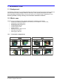
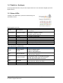
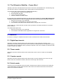
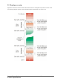
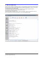
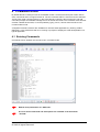
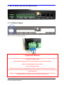
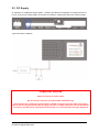
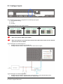
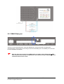
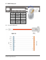
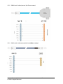
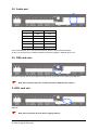
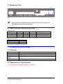
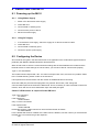
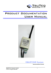
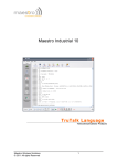
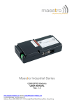
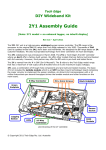
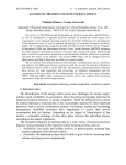
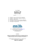
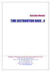
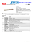
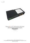
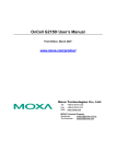
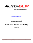
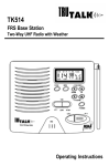
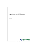
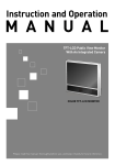
Product Documentation
User Manual
Maestro Industrial 10
Industrial M2M Gateway
Maestro Wireless Solutions
© 2010 All rights Reserved
1
TABLE OF CONTENTS
1 INTRODUCTION ..................................................................................................................4
1.1 Background ..................................................................................................... 4
1.2 What’s new ...................................................................................................... 4
1.2.1 Connection comparisons..........................................................................................4
1.3 System Description ......................................................................................... 5
1.4 Digital vs. Analogue......................................................................................... 6
1.5 Status LEDs .................................................................................................... 6
1.6 The Ultimate in Stability – Comm Alive! ......................................................... 7
2 EVENTS ...............................................................................................................................7
2.1 Digital Input events .......................................................................................... 7
2.2 Timer events.................................................................................................... 7
2.3 Counter events ................................................................................................ 7
2.4 Serial events.................................................................................................... 7
2.5 Analogue events.............................................................................................. 8
3 MI-10 START-UP..................................................................................................................9
4 COMMAND MODE .............................................................................................................10
4.1 Entering Commands...................................................................................... 10
5 MI-10 ELECTRICAL INTERFACES....................................................................................11
5.1 AC Mains Supply ........................................................................................... 11
5.2 DC Supply ..................................................................................................... 12
5.3 Digital Outputs ............................................................................................... 13
5.4 Digital Inputs.................................................................................................. 14
5.5 Analogue Inputs ............................................................................................ 15
5.6 RS485 Data port............................................................................................ 16
5.7 RS232 Data port............................................................................................ 17
5.7.1 PC serial cable pin-out ...........................................................................................17
5.7.2 DB25 serial cable pin-out (for Elster meters) ........................................................18
5.7.3 RJ12 serial cable pin-out (for Landis&Gyr meters) ................................................18
5.8 Audio port ...................................................................................................... 19
5.9 SIM card slots................................................................................................ 19
5.10 SD card slot ................................................................................................. 19
5.11 Expansion Port ............................................................................................ 20
6 ELECTRICAL SPECIFICATIONS.......................................................................................20
7 OTHER SPECIFICATIONS ................................................................................................20
8 SERVICING THE MI-10......................................................................................................21
9 DISCLAIMER ......................................................................................................................24
10 GLOSSARY ......................................................................................................................24
11 REVISION INFORMATION ..............................................................................................24
12 WARNINGS ......................................................................................................................25
13 CONTACTING MAESTRO WIRELESS SOLUTIONS ......................................................25
14 NOTICES & TRADEMARKS ............................................................................................25
Maestro Wireless Solutions
© 2010 All rights Reserved
2
1 INTRODUCTION
1.1 Background
The Maestro Industrial 10 is a versatile industrial RTU (Remote Terminal Unit) with integral modem for
communications to IEDs (Intelligent Electronic Devices). It was primarily developed as an AMR
(Automated Meter Reading) modem, but has since then found a whole range of applications in the
telemetry, SCADA, security, farming, home and office automation industries.
1.2 What’s new
The MI-10 is an upgrade from the previous model with the following new features:
•
Standard IO, RS232 and RS485 on all models (no more Options - but all in one)
•
Casing with more status LEDs
•
External DC input connections
•
2 added Digital outputs
•
2 added Analog inputs
•
Audio interface
•
Expansion port to add more I/O
•
Dual SIM card feature
•
Data logging card slot
1.2.1
Connection comparisons
Maestro Wireless Solutions
© 2010 All rights Reserved
3
1.3 System Description
The MI-10 is a GSM/GPRS terminal intended to be used in industrial telemetry applications. Even
though the MI-10 can act like a GSM modem, it offers much more in terms of communications, inputs,
and event-based programming.
By using simple commands, the MI-10 can switch between using CSD (circuit switched data) calls, or
GPRS to communicate with a device on the serial port. Four fully programmable inputs, timers,
counters and other events provide a very powerful and future-proof solution for industrial
communications.
More input/output expansion units can be added (if required) to increase the total number of digital
inputs and outputs and/or analogue inputs and outputs, to a maximum of seven units.
The following expansion units are available:
•
4X4 I/O – 4X Isolated inputs (digital or analog) and 4X 5A 250Vac relay contact outputs
•
8X smart Input – These 8 inputs can be configured either as pulse counter inputs or normal
digital inputs
•
8X smart Outputs – These 8 outputs can either be 8 internal 5A 250V relays or 8X 100A
external relays
The following expansion units will be available in near future:
•
4X Camera – 4X Camera inputs for capturing photos and video clips per request
•
3 Phase Energy meter – An expansion to connect 3 phase electricity to measure volts,
current, power factor and line quality parameters
The MI-10 executes the scripted Commands that are linked to all the triggered events, as well as
scripted Commands received via SMS / CSD call or GPRS connection.
A triggered event can be, for instance, an input going from high to low or the timer that runs out.
Commands can, for instance, send SMS, report status to a server, toggle an output or clear a timer.
Events
Event A
Event B
Command Lists
Script linked to event A
<Command> <Command> <Command>
<Command>;
Script linked to event B
<Command> <Command> <Command>
<Command> <Command>;
Event C
Script linked to event C
Script contained in SMS
<Command>;
<Command> <Command>;
SMS messages sent to the MI-10 are executed as a script.
Maestro Wireless Solutions
© 2010 All rights Reserved
4
1.4 Digital vs. Analogue
Unless specified otherwise, all inputs and outputs referred to in this manual are Digital inputs and
Digital Outputs
1.5 Status LEDs
A display of 20 LEDs offers a powerful troubleshooting and
verification function:
Modem specific (top line):
LED
Meaning
Power
Power present
GSM Network
GSM Network state
TX
RX
DTR
DSR
RTS
CTS
RI
DCD
Transmit
Receive
Data Terminal Ready
Data Set Ready
Request to Send
Clear to send
Ring Indicator
Data Carrier Detect
States
Off : Not powered
On : Powered
On solid : Searching
Short Flash : Logged on network
Long Flash : Busy in data call
On : Modem transmits data
On : Modem receives data
On : IDE ready
On : Modem ready
On : Meter ready to transmit data
On : Modem ready to accept data
Flash : Ring - waiting to answer
On : Busy in data call or GPRS session
Additional indications (bottom line):
LED
Meaning
Signal
Received Signal
Strength
SIM
SIM card selection
Info
Activity Information
Heart
Heart beat
232
485
RS232
RS485
Maestro Wireless Solutions
© 2010 All rights Reserved
States
1 LED on: Low signal
2 LEDs on: Medium signal
3 LEDs on: Good signal
4 LEDs on: Very good signal
1 : SIM card slot 1 selected
2 : SIM card slot 2 selected
Initialisation : Blink rapidly every 2 seconds
Data connection open : On and blink off rapidly
SMS RX : Blink rapidly while sms is received
SMS TX: Blink slowly while sms is send
GSM mode Idle : Single short blips
GPRS mode Idle : Double short blips
On : Activity on RS232 port
On : Activity on RS485 port
5
1.6 The Ultimate in Stability – Comm Alive!
Telemetry users know that their devices are often in remote or inaccessible areas. The last thing they
can afford is to have to continuously visit a number sites to reset these devices.
There are four major causes of failures in GSM-based telemetry :
1. Lock-ups between modem and GSM network.
2. Not terminated data calls.
3. Loss of network authentication.
4. Unknown network or modem status.
By using proven and patented technology, the MI-10 is kept as stable as possible. Depending on the
customer’s preferences on order, the modem will reset under any of the following conditions :
1. Every 24 hours (only if not in data call).
2. If a data call is unterminated for longer than 45 minutes.
3. If the modem loses GSM network authentication for longer than 10 minutes.
If the modem is in a data call when the 24hr reset cycle starts, the modem will wait for 10 minutes
before resetting.
The default reset options are :
1. Every 24 hours (only if not in data call).
2. If the modem loses GSM network registration for longer than 10 minutes.
2 EVENTS
An event is a change in condition and where certain commands then needs to be executed.
2.1 Digital Input events
Separate Command Lists are linked to the events where an input goes high (on/open) or low
(off/closed). The delay times (also known as the “debounce” times) before the unit registers a change
in input state can be configured. More input/output expansion units can be added to increase the total
number of inputs and outputs.
2.2 Timer events
Separate Command Lists are linked to the events where a timer runs out. There are 10 separate
timers.
2.3 Counter events
Separate Command Lists are linked to the events where a counter reaches one of it’s low or high
levels. There are 10 different counters, each with it’s own high and low levels.
2.4 Serial events
The MI-10 can be configured to execute certain commands when data is received on the serial port.
Typical applications are tag readers and bar-code scanners as well as a whole list of devices that
sends out unsolicited serial data.
Maestro Wireless Solutions
© 2010 All rights Reserved
6
2.5 Analogue events
Separate Command Lists are linked to the events where an analogue value passes a certain level.
The following diagram explains which command lists are associated with which level.
Maestro Wireless Solutions
© 2010 All rights Reserved
7
3 MI-10 START-UP
The MI-10 will print ‘BOOT’ information on start-up. This information is printed on the serial port at the
last baud rate and framing that the MI-10 was set to with command 257. Please see description
of command 257 in the TruTalk manual.
The first line will always print the hardware configuration with <DigIn>X<DigOut>X<AnIn>.
The second line will always print the current firmware version.
The third prints the serial number ext.
The MI-10 is ready for operation once the “Start-up complete!!” sentence is printed. One can now
enter commands via command mode (AT$TT) or use it as a standard modem.
Maestro Wireless Solutions
© 2010 All rights Reserved
8
4 COMMAND MODE
By default the MI-10 serial port acts as a standard modem. However this serial port is also used to
enter commands and to configure the MI-10. The AT command AT$TT is used to enter the standard
TruTeq Text mode command prompt. In this mode the MI-10 will echo all incoming text, and add
command prompts and readable carriage returns as well as line feeds. The command mode will timeout after a default 30 seconds, or can be quitted by typing <ctrl-z>, this will return the MI-10 into
normal modem mode.
A simplified command mode is also available for use with serial applications by entering AT$RT
(RawText). In this mode there will be no echoing or prompts to simplify the serial encapsulation in a
typical application.
4.1 Entering Commands
Commands can be entered once the MI-10 is in command mode.
!
Default serial parameters are: 9600,8,N,1.
!
A List of all the commands and descriptions are available in the document:
“TruTalk”
Maestro Wireless Solutions
© 2010 All rights Reserved
9
5 MI-10 ELECTRICAL INTERFACES
5.1 AC Mains Supply
The MI-10 may be powered from 90VAC to 265VAC. The mains supply is connected to the terminal
block as shown in the following picture :
Important Notices
Even though the MI-10 Industrial will operate without an earth connection, this should always be
connected for safety reasons.
Ensure that the supply wires are inserted and fixed in the correct terminals.
Always use SABS approved mains cables.
Do not used frayed cables.
Please take care when connecting the mains supply, as the possibility of an electric shock
exists if the installer inadvertently touches the live or neutral wires or connects the supply to the
wrong terminals.
Always take all relevant safety precautions. If you are unsure about this – please contact a
qualified person to connect and secure the mains connections
Maestro Wireless Solutions
© 2010 All rights Reserved
10
5.2 DC Supply
An optional Low voltage DC Supply (8Vdc -> 30Vdc) input allows the integrator to configure the MI-10
in such a way that a backup battery or DC PSU can keep the modem alive after loss of mains supply.
Typical connection diagram:
Important Notices
Observe polarity on the DC input!
Do not connect mains AC and external DC simultaneously!
Note that the Low voltage DC supply must be capable of supplying at least 12VA. This means
that, at 12V, the supply must be able to supply 1A. This is not the continuous current that the MI10 requires, but the pulses required when the modem is in communication during a download.
Maestro Wireless Solutions
© 2010 All rights Reserved
11
5.3 Digital Outputs
The MI-10 digital outputs are potential free relay contacts.
Relay 1 (output1) is between pin 1 and 1
Relay 2 (output2) is between pin 2 and 2
The relay’s contacts have the following rating: 30Vdc 1A
The following figure illustrates how the outputs can be connected in a typical application.
Maestro Wireless Solutions
© 2010 All rights Reserved
12
5.4 Digital Inputs
The digital inputs are potential free inputs. A connection must be made between the common (pin C)
and the corresponding digital input, either with a switch, or a relay contact.
Typical connection diagram:
!
Note: The inputs are NOT opto-isolated.
!
Note: Do NOT apply any voltage on either the common or the individual inputs
Maestro Wireless Solutions
© 2010 All rights Reserved
13
5.5 Analogue Inputs
The analogue inputs can be configured for the following input types:
1) 0-5V (default setting)
2) 0-30V
3) 0-20mA
Internal jumper settings as per options above:
Option1 (0-5V)
!
!
Option2 (0-30V)
Option3 (0-20mA)
Note: The inputs are NOT opto-isolated.
Note: The inputs do not need to be set to the same option thus input1 can be 0-5V and
input2 can be set to 0-20mA
Typical analogue connection diagram 1:
•
Analogue input1 monitors the 12V back-up
•
Analogue input2 monitors a level sensor with current source output
Typical analogue connection diagram 2:
•
Analogue input1 monitors a 2 wire sensor (current sink e.g. Truteq temperature probe)
•
Analogue input2 monitors a RPM sensor with voltage output
Maestro Wireless Solutions
© 2010 All rights Reserved
14
5.6 RS485 Data port
The MI-10 comes standard with a secondary RS485 port. If the port has been enabled (with
command !254 1) then the MI-10 will change over from the RS232 port to the RS485 port once startup was completed successfully.
!
Note: An easy way to return to the RS232 port is to start-up the modem with no SIM
card inserted. Once start-up is complete then the modem will stay in RS232 mode and
command !254 0 can be issued.
Maestro Wireless Solutions
© 2010 All rights Reserved
15
5.7 RS232 Data port
The RS232 port is the MI-10's primary data port. It is an RJ45 socket with the following pin-out:
Pin number Description
5.7.1
Direction
1
DCD
Out
2
RX data
Out
3
TX data
In
4
DTR
In
5
GND
-
6
RTS
In
7
CTS
Out
8
RI
Out
PC serial cable pin-out
Maestro Wireless Solutions
© 2010 All rights Reserved
16
5.7.2
DB25 serial cable pin-out (for Elster meters)
5.7.3
RJ12 serial cable pin-out (for Landis&Gyr meters)
Maestro Wireless Solutions
© 2010 All rights Reserved
17
5.8 Audio port
The Audio port is an RJ12.6 socket with the following pin-out:
Pin number Description
Direction
1
+12V
Out
2
MIC+
In
3
SPKR+
Out
4
SPKR-
Out
5
MIC-
In
6
GND
-
The Power between pins 1 and 6 can be used to drive an external audio amplifier.
An RJ11.4 connector from a POTS handset can also be plugged in between pins 2 to 5.
5.9 SIM card slots
The MI-10 is fitted with 2 SIM card push-push slots. Make sure not to insert the SIM card above or
below the required slot as you might then need to open up the MI-10 to retrieve your SIM card.
!
Note: See command !60 in the TruTalk manual for SIM selection options
5.10 SD card slot
The MI-10 is fitted with a micro SD card push-push slot. Add up to a 4GB card to utilize the logging
features.
!
Note: See commands !97 and !98 for logging features
Maestro Wireless Solutions
© 2010 All rights Reserved
18
5.11 Expansion Port
The MI-10 is fitted with an EXP port connector. This is used to connect to expansion input and output
units.
!
Note: Refer to the individual expansion unit's manuals for their features and
operational commands and specifications
6 ELECTRICAL SPECIFICATIONS
Power supply :
Input
Mains (AC)
Mains (DC)
Low voltage DC
Min
85VAC
110VDC
8VDC
Antenna Connector
Type
Gender
Impedance
Max
264VAC
370VDC
30VDC
Max Power
10W
10W
10W
Input Protection
3 X MOV + 2A Fuse
3 X MOV + 2A Fuse
Tranzorb + Poly switch
SMA
Female
50!
7 OTHER SPECIFICATIONS
7.1 Physical
Size
Weight
Casing material
Temperature
rating
Humidity
80mm x 170mm x 35mm
725g
Metal alloy
-20°C to 60°C
Up to 90% RH non-condensing
7.2 Manufacturer’s Type Number
The type number for the Maestro Industrial 10 is MI-10.
Maestro Wireless Solutions
© 2010 All rights Reserved
19
8 SERVICING THE MI-10
8.1 Powering up the MI-10
8.1.1
Using Mains Supply
1.
Switch off or disconnect mains supply
2.
Insert SIM card
3.
Connect data or auxiliary ports
4.
Connect mains power to MI-10
5.
Reconnect mains supply
8.1.2
Using DC Supply
1.
If connected to a DC supply, switch the supply off or disconnect the DC cable
2.
Insert SIM card
3. Connect data or telemetry ports
4.
Connect or power up DC supply
8.2 Configuring the Device
All commands are typed in the terminal window of an application such as Windows HyperTerminal or
preferably with Maestro Wireless Solutions SmartTerminal.
Start off with a test to see if the communications settings are the same between the modem and the
terminal window. If these settings are not the same, you will not be able to communicate properly.
Type in “AT” and ENTER
The modem should respond with “OK”. If it does not respond with “OK”, then there is a problem. Refer
to the Trouble Shooting section further in the document.
It is important that communication with the modem is established before continuing.
Close the COM port (some terminal programs may call this “disconnect”) and change the
communication speed of the software to 9600 baud. This is necessary in order to be able to talk to the
modem, which will now be set to 9600 baud. Open the COM port again.
Check if a PIN number is required for the SIM card
Type in the command:
AT+CPIN?
If the response is :
+CPIN: READY
carry on to the next section
If the response was :
+CPIN: SIM PIN
the Modem requires a PIN number first. Issue the PIN number as follows :
AT+CPIN=00000
For the default PIN number of 00000. If the PIN number is different, use the number you received with
the SIM card. You should now get the response :
OK
Maestro Wireless Solutions
© 2010 All rights Reserved
20
Disable the PIN with the following command :
AT+CLCK=”SC”,0,00000
Where the 00000 is the default PIN number. Use the supplied PIN number if different from 00000.
The response should be :
OK
Important : If you type in the wrong PIN number three times, you will have to unblock the card using
the PUK number. The easiest way is to use your cell phone to unblock the SIM.
Check if the modem is registered on the GSM network
Type in the command:
AT+CREG?
If the response is :
+CREG: 0,1
carry on to the next section
Other possible responses could be :
+CREG: 0,0 – Searching for any network
+CREG: 0,2 – Network found, busy registering
+CREG: 0,5 – Registered on a roaming network
If the response is 0,0 or 0,2, then wait a while for the modem to register. Try the command again until
registered.
If the 0,5 response was received, then the modem is registered on a foreign GSM network. This could
happen close to international border. There may be substantial financial implications if communication
takes place through a foreign network, even if the modem only receives the calls.
Check the signal strength
Type in the command:
AT+CSQ
The response should be at least
+CSQ: 10,0
the 10 indicates signal strength and this result value should be better than 10. The 0 result value is an
indication of the bit error rate on the radio interface, and should be a value from 0 to 7. If this value is
99, it means that the modem has not been able to resolve the error rate.
The modem performs automatic error correction on the radio interface, so the bit error rate is not a
critical value and can be ignored. The important result value is the signal strength.
Set the automatic answer
Type in the command:
ATSO=2
The response should be :
OK
Set the incoming bearer type
Type in the command:
AT+CICB=0
The response should be :
OK
Save the settings
Type in the command:
AT&W
The response should be
Maestro Wireless Solutions
© 2010 All rights Reserved
21
OK
8.3 Troubleshooting
8.3.1
No LEDs come on
Test the supply with an appropriate meter. The values should be within the input voltage ranges.
If the measured voltages are all within range, the modem may be faulty.
8.3.2
Power LED, and CTS LED come on, but the GSM LED won’t flash
If the GSM LED does not start flashing after 10 or 20 seconds, the modem cannot register.
This could mean that the GSM coverage is not adequate (try better antenna positions), that there is a
PIN number required for the SIM card (remove it using the method described), or that the SIM card is
blocked by the GSM network, or even faulty (replace the SIM card).
8.3.3
I get an “OK” for an AT<enter> request, but I can’t program the modem.
You may be in communication with another modem inside your computer. A normal fixed line modem
will respond almost the same a the MI-10, but will give errors when certain (GSM specific) commands
are given to it e.g. AT+CSQ
Try looking for the GSM device on another COM port.
8.3.4
Calls are frequently dropped
This is usually due to either a poor signal strength, or to a backup supply with insufficient driving
capacity when running from backup DC supply.
To test, check the signal strength as follows :
Type in the command:
AT+CSQ
The response should be at least :
+CSQ: 10,0
the 10 indicates signal strength and this result value should be better than 10. The 0 result value is an
indication of the bit error rate on the radio interface, and should be a value from 0 to 7. If this value is
99, it means that the modem has not been able to resolve the error rate.
If the signal strength is lower than 10, try relocating the antenna to a higher position. If you are using a
magnetic mounting antenna, try mounting the antenna on a metal plate. A high gain antenna like a
yagi may also solve the problem.
If the MI-10 is running from a DC Backup supply and signal strength is high, check the supply
capacity to be greater than 1A 12V (>12VA)
Maestro Wireless Solutions
© 2010 All rights Reserved
22
9 DISCLAIMER
Maestro Wireless Solutions does not accept any direct or indirect liability for the use of any Maestro
product. The customer takes full responsibility for its use and any liability or damage that may arise
from the use of the Maestro Wireless Solutions product.
NOTE: This product is not designed or certified for use as medical equipment or with medical
equipment or with medical devices. This product is also not designed or certified to be used with
any medical services or medical related services.
10 GLOSSARY
Abbreviation
API
ASN.1
CDR
CSV
DB
DNS
FQDN
GAIN
HTTP
HTTPS
IVR
I/O
IP
MMS
MMSC
PDA
SMSC
SMPP
USSD
WIG
WAP
WML
WASP
XML
Description
Application programmers Interface
Abstract Syntax Notation One
Charge Data Record
Comma Separated Values
Database
Domain Name System
Fully Qualified Domain Name
Gateway Application and Interface Node
Hypertext Transfer Protocol
HTTP Secure
Interactive Voice Response
Input/Output
Internet Protocol
Multimedia Message Service
Multimedia Messaging Service Centre
Personal Digital Assistant
Short Message Service Centre
Short Message Peer to Peer Protocol
Unstructured Supplementary Services Data
Wireless Internet Gateway
Wireless Application Protocol
Wireless Mark-up Language
Wireless Application Service Provider
Extensible Markup Language
11 REVISION INFORMATION
Date
09 November 2010
Version
1.0
Maestro Wireless Solutions
© 2010 All rights Reserved
Comments
Author
Eric Guldemond
Create document
23
12 WARNINGS
WARNING: Do not open this equipment under any circumstances. High risk of electrical shock exists that may
and probably will lead to injuries and/or death.
13 CONTACTING MAESTRO WIRELESS SOLUTIONS
Telephone
Fax
Web
email
+852 2869 0688
+852 2525 4701
www.maestro-wireless.com
[email protected]
Maestro Wireless Solutions Ltd
3603-09, 36/F., 118 Connaught Road West
Hong Kong
HONG KONG
14 NOTICES & TRADEMARKS
Copyright Notice
Copyright © 2010 Maestro Wireless Solutions LTD. All rights reserved. No part of this document may be
reproduced in any form or by any means without prior written authorization from Maestro Wireless Solutions LTD
Trademarks
Maestro Wireless Solutions and the Maestro corporate logo are trademarks of Maestro Wireless Solutions. All
other trademarks appearing in this guide are the exclusive property of their respective owners.
General Notice
Maestro Wireless Solutions reserves the right to revise this document without obligation to provide notification of
such changes. Maestro Wireless Solutions provides this documentation without warranty expressed, implied,
statutory, or otherwise, and specifically disclaims any warranty of merchantability or fitness for a particular
purpose. Maestro Wireless Solutions may make improvements or changes in the product(s) and/or the
program(s) described in this documentation at any time. Maestro Wireless Solutions assumes no responsibility
for product reliability and/or performance if any party other than Maestro Wireless Solutions modifies the device
configuration or if the installation is not performed in accordance with this manual.
Maestro Wireless Solutions
© 2010 All rights Reserved
24