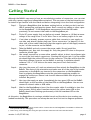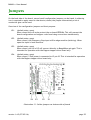
1
BEBOPR++
USER MANUAL
Copyright © AES allround embedded services 2012-2014
Author:
Version:
Date:
Bas Laarhoven
1.4.2
28 February 2014
BeBoPr++ User Manual
Disclaimer, Warranties and Liability
Disclaimer
UNLESS OTHERWISE MUTUALLY AGREED TO BY THE PARTIES IN WRITING, LICENSOR OFFERS THE
PRODUCT AS-IS AND MAKES NO REPRESENTATIONS OR WARRANTIES OF ANY KIND CONCERNING
THE PRODUCT, EXPRESS, IMPLIED, STATUTORY OR OTHERWISE, INCLUDING, WITHOUT
LIMITATION, WARRANTIES OF TITLE, MERCHANTIBILITY, FITNESS FOR A PARTICULAR PURPOSE,
NONINFRINGEMENT, OR THE ABSENCE OF LATENT OR OTHER DEFECTS, ACCURACY, OR THE
PRESENCE OF ABSENCE OF ERRORS, WHETHER OR NOT DISCOVERABLE. SOME JURISDICTIONS
DO NOT ALLOW THE EXCLUSION OF IMPLIED WARRANTIES, SO SUCH EXCLUSION MAY NOT APPLY
TO YOU.
Warranties
THERE IS NO WARRANTY FOR THIS DESIGN, TO THE EXTENT PERMITTED BY APPLICABLE LAW.
EXCEPT WHEN OTHERWISE STATED IN WRITING THE COPYRIGHT HOLDERS AND/OR OTHER
PARTIES PROVIDE THE DESIGN “AS IS” WITHOUT WARRANTY OF ANY KIND, EITHER EXPRESSED
OR IMPLIED, INCLUDING, BUT NOT LIMITED TO, THE IMPLIED WARRANTIES OF
MERCHANTABILITY AND FITNESS
FOR A PARTICULAR PURPOSE. THE ENTIRE RISK AS TO THE QUALITY AND PERFORMANCE OF THE
DESIGN IS WITH YOU. SHOULD THE DESIGN PROVE DEFECTIVE, YOU ASSUME THE COST OF ALL
NECESSARY SERVICING, REPAIR OR CORRECTION.
Limitation on Liability
EXCEPT TO THE EXTENT REQUIRED BY APPLICABLE LAW, IN NO EVENT WILL LICENSOR BE LIABLE
TO YOU ON ANY LEGAL THEORY FOR ANY SPECIAL, INCIDENTAL, CONSEQUENTIAL, PUNITIVE OR
EXEMPLARY DAMAGES ARISING OUT OF THE USE OF THIS PRODUCT, EVEN IF LICENSOR HAS BEEN
ADVISED OF THE POSSIBILITY OF SUCH DAMAGES.
Beware: Just like the BeagleBone itself, this BeBoPr++
expansion board may be totally unsuitable for any purpose!
Only use it if you fully understand the risks involved and
have taken proper measures to prevent personal injury
and/or material damage.
version 1.4.2 (27/02/14)
page 2
BeBoPr++ User Manual
Table Of Contents
Disclaimer, Warranties and Liability.......................................................................2
Disclaimer..................................................................................................2
Warranties .................................................................................................2
Limitation on Liability....................................................................................2
Table Of Contents............................................................................................3
Introduction...................................................................................................5
Getting Started...............................................................................................6
The Third Generation........................................................................................7
What has changed.........................................................................................7
What did not change....................................................................................10
BeBoPr++ Features..........................................................................................11
Generic I/O view.........................................................................................11
3D printer specific I/O view...........................................................................12
NC router specific I/O view............................................................................13
Software......................................................................................................14
Linux operating system.................................................................................14
3D-printer software.....................................................................................14
LinuxCNC..................................................................................................15
Other NC Applications...................................................................................15
The Cape.....................................................................................................16
Power......................................................................................................16
Configuration EEPROM..................................................................................16
Daughter modules.......................................................................................17
Connections..................................................................................................19
Power Connections......................................................................................19
Stepper Motor Connections............................................................................20
Stepper signals connector..............................................................................20
Thermistor connectors..................................................................................21
Limit switch connectors................................................................................21
PWM / analogue outputs................................................................................21
PWM Power Outputs........................................................................................22
BeBoPr++ improvements................................................................................22
Free-wheeling diodes...................................................................................23
Power dissipation........................................................................................23
Analogue inputs.............................................................................................25
Signal Conditioning......................................................................................25
Protection.................................................................................................26
Scaling.....................................................................................................26
Voltage inputs............................................................................................26
Thermistor curve........................................................................................26
Plug-in stepper drivers.....................................................................................28
I/O enable....................................................................................................30
Indicator LEDs...............................................................................................31
Power LEDs................................................................................................32
Status LEDs...............................................................................................32
Input signal LEDs.........................................................................................32
Output signal LEDs.......................................................................................32
version 1.4.2 (27/02/14)
page 3
BeBoPr++ User Manual
Switches......................................................................................................33
Fuses..........................................................................................................34
Jumpers......................................................................................................35
I2C and Emergency Stop...................................................................................36
Emergency Stop Input...................................................................................36
I2C Bus.....................................................................................................36
Specifications (preliminary)...............................................................................37
Connectors...................................................................................................38
Mating Connectors..........................................................................................40
I/O connectors:..........................................................................................40
Power connectors:.......................................................................................41
Troubleshooting.............................................................................................42
References...................................................................................................43
Board dimensions...........................................................................................44
version 1.4.2 (27/02/14)
page 4
BeBoPr++ User Manual
Introduction
The BeBoPr++ is the third generation of BeBoPr boards. It integrates the original/classic
BeBoPr and the Bridge that was necessary to use the BeBoPr with the BeagleBone Black.
By integrating the Bridge, the BeBoPr++ stays compatible with both the original BeagleBone
and the BeagleBone Black. It also reduces complexity and manufacturing costs.
This manual tries to provide all information necessary to install, operate and troubleshoot
the BeBoPr++ .
This manual is still work-in-progress. Partly the content may still refer to the original
BeBoPr and may not be applicable on the BeBoPr++. Please do not hesitate to report errors
and/or send other (constructive) feedback to the author ([email protected]).
version 1.4.2 (27/02/14)
page 5
BeBoPr++ User Manual
Getting Started
Although the BeBoPr may seem to have an overwhelming number of connectors, one can start
with only a power supply and a BeagleBone attached. This way some of the functionality can
be tested to get familiar with the board and before integrating it into the final configuration.
Step 1 - First get a BeagleBone that has been working before, so that you don't run into
USB or networking configuration issues. Don't connect any cables or other capes
to the BeagleBone†. If the BeagleBone was powered from the USB cable
previously, do not connect that cable to the BeagleBone yet.
Step 2 - Find a DC power supply that can deliver at around 1 Ampere or 10 Watt at some
voltage in the range from 12 to 24 Volts. Even a car battery might do for now.
Step 3 - If not done so already, prepare a power cable that connects to your supply on
one side, and attach a power plug (see “Power connectors:”on page 41) to the
other side of that cable. Make sure that the negative pole of the supply connects
to pin 1 of the connector on the BeBoPr.
Step 4 - Take the BeBoPr and only connect the power cable. Do not install the
BeagleBone yet. Now turn the supply on. Only the green LED close to the power
connector should light.
Step 5 - Use a small screwdriver or some other metallic object to short two adjacent pins
on one of the limit switch connectors‡. Shorting the left pin (pin 1) to the middle
pin should light the yellow LED next to the connector. This step verifies that the
step down voltage converter on the BeBoPr is working. A voltmeter should
measure 5.00 +/- 0.05 Volts on the outer two pins of each limit switch
connector.
Step 6 - Now turn the power off, wait one minute and then attach the BeagleBone to the
BeBoPr. Take note of the orientation and make sure all of the pins of the header
connectors on the BeBoPr are inserted in the connectors on the BeagleBone.
Start by aligning the BeagleBone onto the pins before applying pressure to
engage the connectors. Have a look from all sides and make sure all pins are
inserted. Be gentle!
Step 7 - Now turn the supply on again. Immediately the two green LEDs on the BeBoPr
should light, as well as some of the blue LEDs on the BeagleBone. You can now
connect a network cable or USB cable.
Step 8 - Wait for the BeagleBone to boot. Use the console cable if available to view the
boot process. Shortly after Linux has started, the yellow status LED on the
BeBoPr should start blinking synchronously with the heartbeat LED on the
BeagleBone.
At this point, the BeagleBone is running a suitable kernel and the device tree overlay was
loaded successfully. This procedure can always be used as a first test to diagnose problems.
† The only exception being a serial console cable. Connect that to the BeagleBone if available to follow the
boot process and ease debugging.
‡ Don't worry, even shorting the wrong two pins on these connectors will not harm the board.
version 1.4.2 (27/02/14)
page 6
BeBoPr++ User Manual
The Third Generation
This chapter summarizes the differences between the original BeBoPr and the BeBoPr++. It
contains useful information for users that already own a BeBoPr or are otherwise familiar
with the BeBoPr specifications.
Illustration 1 - BeBoPr++ R1 prototype
What has changed
Board layout
The BeBoPr++ has gotten a complete new board layout. All SMD components were moved from
the bottom side to the top side. There are no longer components underneath the board,
reducing the overall board height and manufacturing costs.
The choice of components makes it no longer possible to solder the board only a soldering
iron. As the board was never officially offered as DIY kit, this shouldn't be an issue.
Elevated BeagleBone mounting
With the BeBoPr Bridge, the distance between the BeagleBone and the BeBoPr was increased.
This allowed access to the serial console connector on the BeagleBone as well as the USB host
version 1.4.2 (27/02/14)
page 7
BeBoPr++ User Manual
port, HDMI connector and uSD card slot while mounted on the BeBoPr. This feature was
propagated into the design of the BeBoPr++. Extended pin-header connectors create a similar
gap between BeBoPr++ and BeagleBone.
Wide input power range
The step down converter has been re-designed to operate from a DC supply voltage in the
range from 12 to 24 Volts. It's still using the same (proven) step down converter as before but
some of the components have changed so that it now can operate at 24 Volts too.
More power for heaters
Since the input supply voltage is also used for the heater outputs, these can now generate
more heat (power) without exceeding the maximum allowed currents. The input power
connector has also been replaced by a type that allows 16A (instead of 12A) of continuous
current. Now it is possible to control a heated build platform and an extruder simultaneously
without exceeding the maximum current specifications.
Single fuse
The expensive and hard to get SMD fuses on the three PWM outputs have been replaced by a
single 5×20 mm fuse. This fuse is now placed into the board's input power line.
Input power LED
A green LED located near the input power connector indicates the presence of supply power.
It will not light if the fuse has blown. This LED replaces the three green LEDs
I2C connector
The BeagleBone's I2C2 bus is now routed to a 4 pin connector, no need to solder wires directly
to the board any more. This allows I/O expansion or connection of a simple I2C LCD. A level
shifter allows connection of 3.3 or 5 Volt powered devices without chance of damaging the
BeagleBone.
Emergency Stop input
The BeBoPr now also has a hardware emergency stop (ESTOP) input. Activation of the ESTOP
signal negates the I/O enable without depending on the software. The ESTOP immediately
disables the PWM outputs and stepper signals. A red LED signals the ESTOP state.
If preferred, the ESTOP signal can be configured to latch (remain active once asserted) until
it's cleared by software (negation of the I/O enable signal). Closing a jumper on the BeBoPr
activates the latch.
The ESTOP signal should connect to a normally closed contact or some open collector / open
drain type sensor. When not used, a jumper or piece of wire can replace the sensor. An
external opto coupler / isolator can be used to interface to 24 Volt signals.
version 1.4.2 (27/02/14)
page 8
BeBoPr++ User Manual
Improved PWM outputs
The PWM output stages have been redesigned to generate less heat in the output switches
(FETs) and allow up to 32 kHz PWM switching frequency without significant losses. The TO220
FETs have been replaced by SMD parts with lower RDSon. The 'heated-bed' output now can
deliver 120 Watt (10 A) at 12 Volt, or up to 200 Watt (8 A) at 24 Volt. Most heated build
platform can now connect without the need for an external mechanical or solid state relay.
All PWM outputs now have on-board free-wheeling diodes as described in the section named
“PWM / analogue outputs“. These diodes protect the FETs (and the rest of the board) from
the voltage spikes that occur when switching at high speed or with inductive loads †.
I/O enable LED
This LED indicates that the I/O devices are 'live'. An inadvertently de-activated I/O enable
will prevent the I/O signals to function properly. This was not always obvious and hard to
debug, now this signal's state is directly visible.
Larger bypass capacitor for stepper modules
The bulk capacitance that bypasses the stepper motors power supply has been increased. A
high quality 220 uF/50V electrolytic capacitor has been added. This should prevent damage
to the Pololu stepper driver modules caused from over-voltage spikes generated by the
motors.
Reset button
The location of the reset button was moved to the opposite side of the board. It's now
situated next to the power button, beneath the power jack on the BeagleBone.
Sensor power
The 5 Volts on the limit sensor input connectors is no longer controlled by the BeagleBone but
available as soon as board input power is present. This supply can be used for many limit
switches that need a supply to function (e.g. optical sensors or three wire industrial proximity
sensors) or special functions that need 5 Volt when the BeagleBone is not present or has been
powered down.
† For EMC reasons it may still be necessary to mount an anti-parallel free-wheeling diode directly on the load.
version 1.4.2 (27/02/14)
page 9
BeBoPr++ User Manual
What did not change
Dimensions
The board dimensions and mounting hole pattern have remained the same.
Connectors
All connectors have remained the same and are compatible with the original BeBoPr
connectors†. The locations on the board haven't changed either, making the BeBoPr++ a plugin replacement for BeBoPr+ boards or BeBoPr-with-Bridge combinations.
The new connectors (for the I2C bus and the ESTOP input) are located between the reset
button and the stepper motor power connector, beneath the RJ45 connector of the
BeagleBone.
Software Compatibility
The hardware is backwards compatible with the BeBoPr+ and BeBoPr with Bridge. No software
changes should be necessary to operate a BeBoPr++ with the software designed for a BeBoPr+
or BeBoPr-with-Bridge.
† When using the extra current that the BeBoPr++ can deliver compared to the BeBoPr and BeBoPr+ boards, the
power plugs and wiring should to be changed to handle the extra current. Read more on this subject in Mating
Connectors on page 40.
version 1.4.2 (27/02/14)
page 10
BeBoPr++ User Manual
BeBoPr++ Features
Although designed as 3D printer controller, the BeBoPr++ can be used for many other
applications. This chapter describes the interfaces in a generic way first, followed by
mapping these features on 3D printer hardware.
Generic I/O view
Analogue inputs (3x)
Three analogue inputs accept a 0 - 3.6 Volt input range. The inputs are protected against
over-voltage: Accidental shorts between thermistor wires and the 12 Volt supply voltage will
not destroy the BeagleBone.
The input filter scales (by a factor 0.5) and limits the analogue input signals to the
BeagleBone's 0 - 1.8 Volt range.
Instead of using the troublesome BeagleBone's on-chip ADC, a more stable 12-bit ADS1015 is
present on the BeBoPr++. It operates in parallel to the BeagleBone's ADC and uses a standard
Linux driver.
Analogue (PWM) outputs (3x)
Three high power outputs are connected to the processor's PWM devices. These outputs can
also be used as digital outputs, to control a relay, a motor, or other DC load.
Digital inputs (6x)
Six digital inputs can be used for simple logic signals, or to connect switches or opto sensors
directly. The three pin connectors also provide a +5 Volt signal for sensors that need a supply
voltage. The supply is protected against short-circuits by a thermal fuse.
Digital outputs (12x)
Twelve +5 Volt TTL/CMOS level compatible outputs are available on a header connector.
These outputs can be switched to tristate via software and by an active low disable signal.
Supply
The board can operate from a single power supply that provides a DC voltage in the range
12 to 24 Volts. If required, the stepper drivers can operate from a different supply than that
is used for the board. An efficient step down converter generates the 5 Volt supply for the
BeagleBone. This makes the BeBoPr++ compatible with almost any kind of DC power
version 1.4.2 (27/02/14)
page 11
BeBoPr++ User Manual
source. Choose between a cheap ATX power supply, a simple laptop 18-20 Volt adapter, an
adjustable lab bench supply, an industrial 24 Volt supply or whatever is available and can
deliver sufficient power for your application.
3D printer specific I/O view
Stepper outputs
The BeBoPr has four sockets for Pololu, StepStick or compatible modules. If these modules are
used, the motors connect to the 4-pin connectors next to the module sockets on the BeBoPr.
Applications requiring more powerful stepper drivers can connect these drivers to the pinheader connector that is located between the Pololu sockets and that carries all relevant
signals to control up to 5 axes.
Limit switch inputs
These inputs accept a mix of mechanical switches and/or optical-sensors. They can connect
directly to slow changing input signals because of the Schmitt Trigger inputs. Each input has a
5 Volt supply pin for external sensors that need power to operate. This supply can deliver 0.3A
for all inputs combined and is short circuit protected by a thermal fuse.
Power outputs
Three powerful outputs can generate PWM signals for motors and/or heaters, or analogue
signals for laser power control. These outputs can be controlled directly by the high
resolution PWM controllers in the AM335X processor, or via GPIO signals for bit-bang or simple
on/off control.
The output closest to the board power input connector J20 is dimensioned to deliver 120 W to
200 W, depending on the voltage used (10A @ 12 Volts or 8A @ 24 Volts). The other two
outputs can deliver 4A each (50 W @ 12 Volts or 100 W at 24 Volts). Note that the combined
current drawn should not exceed the 16 A specification!.
The power switching FETs have very low RDSon and are driven by MOSFET drivers. They can
operate at high switching frequencies with relatively low switching losses.
Connecting inductive loads can cause all kinds of trouble, ranging from HF noise up to a
damaged BeBoPr. Always use a free-wheeling diode directly over the load. This keeps the
current loop (coil!) as small as possible and reduces the area polluted by the EMI noise.
Use of high current loads may require forced air cooling of the board (FETs, diodes and fuse).
This prevents parts from overheating, melting the solder and possibly destroying the BeBoPr,
your home or even worse. Make sure to also read the chapter on “FET power dissipation”.
Always be careful, start conservative and test. Increasing power only if you feel comfortable
with the results of the previous step.
version 1.4.2 (27/02/14)
page 12
BeBoPr++ User Manual
Warning: Some of the components can get very hot, too hot to touch! If in doubt, use a
moistened finger before probing a package†.
Never ever leave your system unattended when playing with these kinds of high currents!
The intention is to generate heat, but sometimes the heat will appear at an unexpected
location: An oxidized connector, a connector screw not tightened properly, a bad solder joint.
Any place with some resistance becomes important!
Thermistor Inputs
The analog inputs are used for thermistors that measure the temperature of the temperature
controlled devices, often the heated build platform (HPB or bed) and up to two extruder(s)
NC router specific I/O view
A router will use the stepper signals and limit switches just like a 3D-printer. The power
outputs and analog inputs are free to use for other purposes.
† Be careful and don't use a 'wet' finger as that may cause shorts!
version 1.4.2 (27/02/14)
page 13
BeBoPr++ User Manual
Software
The BeBoPr++ can be used with all BeagleBone versions. The classic (white) and the
BeagleBone Black are both hardware compatible with the BeBoPr++.
The BeBoPr++ cape's on-board EEPROM holds configuration information for both the 3.2
kernel (I/O multiplexer settings) and the device tree based 3.8 kernels. The board identifies
itself as 'cape-bebopr-brdg'.
Linux operating system
BeagleBone (classic)
The first BeagleBone used kernel 3.2. This kernel used information from the EEPROM on the
BeBoPr to configure the I/O properly. The 3.8 kernel used for the BBB will also work on this
BeagleBone.
BeagleBone Black
The BBB uses device tree overlays to configure the processor's I/O subsystem. The proper
overlay is selected by configuration information in the EEPROM on the BeBoPr. The
BeagleBone Black needs kernel 3.8 or later.
3D-printer software
Open source BeBoPr code
An open source code repository to build a 3D printer with the BeBoPr++ is available at
https://github.com/modmaker/BeBoPr. This code uses one of the PRU coprocessors for the
step pulse generation and can freely be changed.
PRU stepper code
Each BeBoPr++ comes with a license for use of the PRUSS stepper driver firmware. This
stepper driver is proprietary code that runs on a PRU co-processor and is stored in the
BeBoPr++'s on-board EEPROM. The driver handles deterministic and accurate timing of the
stepper pulses for all four axes simultaneously. It also generates the acceleration and
deceleration ramps. Via the API†, custom applications can easily generate accurate stepper
† The API can be found in the open source BeBoPr code.
version 1.4.2 (27/02/14)
page 14
BeBoPr++ User Manual
motor control without needing extra hardware or highly specialized real-time code.
LinuxCNC
LinuxCNC has been around for a long time. Originally Intel X86 only, was developed to control
mills, lathes and routers. Since the port to the BeagleBone, its also being used for 3D
printers. Both orthogonal (XYZ) types and Kossel style delta printers.
As an alternative for the BeBoPr code, open source purists will probably like LinuxCNC more.
It has support for the BeBoPr since the original (first) BeBoPr and all software, including the
PRU stepper code is open source. As a community effort, it evolves faster than the BeBoPr 3D
printer code.
Other NC Applications
What has been written about 3D-printer software above also applies for other numerical
control applications. Being it a simple router, a laser engraver or another dedicated machine.
These applications will probably not need the PWM heater outputs from the BeBoPr. But often
they need to control devices like a spindle, coolant fluid pump or laser power supply. These
can then be controlled from the otherwise unused outputs.
Unlike 3D printers and small routers, a real mill or big router will require more powerful
stepper motors than will fit on the BeBoPr In that case, instead of using the Pololu kind of
plug-in stepper modules, off-board power stepper drivers can be used. This way LinuxCNC can
control up to 5-axis that connect via a flat-cable to the BeBoPr.
version 1.4.2 (27/02/14)
page 15
BeBoPr++ User Manual
The Cape
Illustration 2: - BeBoPr features on an early prototype
Power
The on-board switching step-down converter creates the 5 Volts DC required for the
BeagleBone, BeBoPr and (external) digital inputs.
Configuration EEPROM
The BeBoPr uses an on-board EEPROM to identify itself to the BeagleBone.
version 1.4.2 (27/02/14)
page 16
BeBoPr++ User Manual
For 3.2 kernels (used by the original BeagleBone), the pinmux configuration is read from the
EEPROM during kernel start-up. All inputs and outputs are configured accordingly (this
requires kernel 3.2.16 or later).
The 3.8 kernels used by the BeagleBone Black have a different way to set the pinmux
configuration. During boot the cape's identifier is read from the EEPROM and the
corresponding Device Tree Overlay is loaded. The DT overlay defines the configuration of the
inputs and outputs, as wel as the configuration of various subsystems from the processor.
The EEPROM address of the BeBoPr cape is factory set to 0x54.
Daughter modules
Illustration 3: BeBoPr - daughter modules
The BeBoPr cape is designed to act as base board for the BeagleBone module and (optionally)
the stepper driver modules as shown in the illustration below.
Because of the board size and the amount of cables needed to connects all devices to the
BeBoPr, the stacking order has been reversed, and the BeagleBone sits on top of the cape
instead of the other way around. The cape has four mounting holes for attachment to a flat
version 1.4.2 (27/02/14)
page 17
BeBoPr++ User Manual
surface. Spacers with a minimum height of 4 mm are needed to prevent shorting pins on the
bottom side of the cape.
Although BeagleBone and its capes are designed to form a stack of undetermined height,
there can only be a single BeBoPr and a single BeagleBone in the stack. The BeagleBone is
always the first board of a stack, and the BeBoPr cape is always the last, because neither
board has stack-through connectors.
Other capes can be stacked between the BeBoPr and the BeagleBone, but not all
combinations will work properly. This depends on the signals used by the other capes.
version 1.4.2 (27/02/14)
page 18
BeBoPr++ User Manual
Connections
Power Connections
J18 – Stepper driver power. Connect a 12-24 Volt DC (+/- 10%) regulated power supply. Can be
left unconnected if no Pololu-like stepper drivers modules are used.
J20 – Board power. Connect a 12-24 Volt DC regulated power supply. This is the supply for the
BeagleBone and the high-power PWM outputs.
Both connectors have the ground on pin 1 and the supply / plus on pin 2.
Illustration 4: BeBoPr cape - connectors
version 1.4.2 (27/02/14)
page 19
BeBoPr++ User Manual
WARNING: Do not exceed the maximum specified current for these connectors.
WARNING: Do not connect power to the DC INPUT (P5) jack on the BeagleBone once mounted
on the BeBoPr. This will most likely damage the BeBoPr and/or the supply connected to the
DC INPUT.
Stepper Motor Connections
If the BeBoPr has the stepper driver modules on board, the four stepper motors connect to
J15, J16, J17 and J19. In that case connector J5 is hidden underneath the driver modules and
can not be used.
J15 – X-axis, pins 1&2 motor coil-A, pins 3&4 motor coil-B
J16 – Y-axis, pins 1&2 motor coil-A, pins 3&4 motor coil-B
J17 – Z-axis, pins 1&2 motor coil-A, pins 3&4 motor coil-B
J19 – E-axis, pins 1&2 motor coil-A, pins 3&4 motor coil-B
Stepper signals connector
J5 – all stepper signals are present on this connector. It connects directly to the 15 pin sub-D
connector of a TB6560-4V5 3A stepper driver board sold on e-Bay.
Pin nr Direction
1
Signal
AM3359 pin
GND
2
in/out
EXT_VCC (sense)
3
out
#STEPPER_IO_SELECT
4
out
Z_ENA_BUF
V5
5
out
Y_ENA_BUF
T4
6
out
E_DIR_BUF
U9
7
out
E_STP_BUF
R6
8
out
Z_DIR_BUF
R5
9
out
Z_STP_BUF
U5
10
out
Y_DIR_BUF
T3
11
out
Y_STP_BUF
T2
12
out
X_DIR_BUF
R4
13
out
X_STP_BUF
R3
14
out
E_ENA_BUF
V9
15
out
X_ENA_BUF
T1
16
N/C
Table 1: J5 stepper driver signals
version 1.4.2 (27/02/14)
page 20
BeBoPr++ User Manual
If the BeBoPr controls external stepper drivers, the stepper motors connect directly to these
drivers and the connectors J15, J16, J17 and J19 are not used. The stepper signals for the
external drivers connect to J5.
Thermistor connectors
Designed for use with 100kΩ thermistors (e.g. Epcos B57560G104F) or any low impedance
analogue signal source. For the latter one should take into account that a 3.60 Volt voltage
source with an internal resistance of 2.05 kΩ is connected parallel to the input pins.
J6 – Thermistor 0 – BeagleBone AIN4 and ADS1015 channel 0
J7 – Thermistor 1 – BeagleBone AIN5 and ADS1015 channel 1
J8 – Thermistor 2 – BeagleBone AIN6 and ADS1015 channel 2
Limit switch connectors
J9
– X-max limit sensor – BeagleBone gpio69
J10 – X-min limit sensor – BeagleBone gpio67
J11 – Y-max limit sensor – BeagleBone gpio26
J12 – Y-min limit sensor – BeagleBone gpio68
J13 – Z-max limit sensor – BeagleBone gpio33
J14 – Z-min limit sensor – BeagleBone gpio27
All limit switches have a +5 Volt supply pin (pin1), a ground pin (pin 3) and a signal pin inbetween (pin 2). The input is pulled high to the 5 Volt by a 560 Ω pull-up resistor in series
with a LED. Connecting pin 2 to the ground (pin 3) will activate the LED and change the signal
on the gpio pin of the BeagleBone to a '1' (active).
Because of the hysteresis built into the input level shifters, these can connect directly to
optical slot sensors with an open collector (-like) output. In that situation the LED may
continue to glow weakly in the off situation, but that is clearly distinguishable.
Note 1: The IO enable must be active before the inputs signals can be seen by the
BeagleBone.
Note 2: The level shifter is inverting the input signal, so a 'low' input signal will activate the
LED and read back as a '1' on the BeagleBone gpio input.
PWM / analogue outputs
J2 – PWM0 – BeagleBone ehrpwm2B
J3 – PWM1 – BeagleBone ehrpwm2A
J4 – PWM2 – BeagleBone ehrpwm1A
version 1.4.2 (27/02/14)
page 21
BeBoPr++ User Manual
PWM Power Outputs
Output stages
The PWM outputs on the BeBoPr++ can be configured in software to operate at up to very high
frequencies. 100 kHz PWM at 10 A is possible, but this will generate a lot of EMI and some
dissipation in the FETs. It's advisable to use a more conservative frequency to reduce the
amount of heat and EMI generated.
The MOSFET output stages are shown in illustration 5. The fused 12 - 24 Volt power comes in
at the top connection. On the right side the wires go to the three output connectors. The
wires on the left side connect to the push-pull MOSFET drivers used to drive the gates. The
third (bottom) output is the 10A HBP/bed output and it has two FETs in parallel to reduce the
dissipation.
Illustration 5 - PWM output stages
Illustration 6 shows a thermal picture of the BeBoPr++ HBP/bed output when feeding a 10A
load at 40 kHz / 98% duty-cycle. Most heat is being dissipated in the fuse on the right. The
free-wheeling diode in the center of the top image (just between the rightmost FET and the
output connector) is also getting a little warmer than the FETs.
version 1.4.2 (27/02/14)
page 22
BeBoPr++ User Manual
Illustration 6 - Temperature profile 10A PWM
Free-wheeling diodes
If an inductive load is installed, a free-wheeling diode should be used. A simple silicon
rectifier diode of type 1N4007 or compatible will do in some situations, in other cases a fast
recovery type will be better. It reduces the EMI and protects the BeBoPr and BeagleBone from
voltage spikes. Place this diode as close to the load as possible, or as a last resort, mount it
together with the wires of the load at the output connector. Connect the diode anti-parallel
to the load. i.e. connect the + or Anode to the negative output terminal and the – or Cathode
to the positive output terminal.
Power dissipation
Most of this section is not applicable for the BeBoPr++ because of changes to that part of
the design. As the information herein is still correct and applies to BeBoPr boards with
TO-220 FETs, this section has not been removed.
version 1.4.2 (27/02/14)
page 23
BeBoPr++ User Manual
Some example calculations to show the effect of large currents:
The dissipation (power lost in the FET) roughly depends on three factors: The current through
the FET, the switching frequency and the temperature of the FET.
Using the FET to switch (mainly resistive) heaters for a 3D-printer does not require high speed
switching. Switching between 1Hz and 100 Hz makes the switching losses marginal and only
the current through the FET and the FET's internal temperature are important.
Power dissipated in the FET is proportional with the current squared (P=I2×R):
When a 4A current flows through the FET, and the sum of Rdson and other resistive elements
in the FET is 50 milliOhm, a 200 mV voltage drop over the FET generates 0.8 W of dissipation
in the FET.
If we increase the current to 6A, assuming the FET is still kept at the same temperature, the
dissipation in the FET rises to 300 mV × 6 A, or 1.8 W !
At 8A, the dissipation reaches 3.2 W, four times the dissipation at double the current!
But another effect gets important: If the temperature of a FET rises, the Rdson increases too.
The Rdson will double if the FET's (internal) temperature rises from 25 degrees to 175 degrees
Celsius. This resistance increase of 100% will also increase the power that is dissipated in the
FET with 100%. The resulting temperature rise will increase the resistance further. Increasing
dissipation and temperature even further. This so-called thermal run-away must be prevented
by cooling the FET adequately.
If dissipation in a FET is kept below 1 W and ambient temperature is normal, no further
cooling of the FET is necessary. Above that, precautions have to be taken to keep the FET
cool.
The first step is to use a clip-on heat-sink. Both Aavid Thermaloy and Fisher have clip-on heatsinks. Aavid series 5768 and Fisher FK237 and FK240 will fit. These can handle around 2-4
Watts depending on type, and more with some forced air flow.
AAVID THERMALLOY - 576802B00000G. - HEAT SINK, FOR TO-220
FISCHER ELEKTRONIK - FK 237 SA 220 O - HEAT SINK, TO-220
version 1.4.2 (27/02/14)
page 24
BeBoPr++ User Manual
Analogue inputs
The AM335x processor has an integrated Analog to Digital Converter that can be used as touch
screen controller and as general purpose ADC. This converter is called the TSCADC hereafter.
Because of erratic behaviour of this converter† with the 3.2 kernel, the original BeBoPr had
the option to mount an extra ADC for more accurate results. With the BeagleBone black and
the 3.8 kernel performance even got got worse, so the the extra 12 bit converter is now
standard on the BeBoPr++ boards, until a software solution is found. This converter is called
the ADS1015.
Both ADCs operate in parallel on the same signals and either one can be used for the
application.
Signal Conditioning
Some signal conditioning is done before feeding the analogue signal to the ADCs. For a proper
understanding of the transfer function, the input circuit of the first thermistor is shown
drawn in illustration 7. The same circuit is available on all analogue inputs. VCLAMP and
PWR_THRM0 are low impedance sources. VCLAMP is 3.4 Volts and PWR_THRM0 is twice the
reference voltage of the AM335X ADC.
Illustration 7 - Analogue Input
† Some driver problems have been identified but there's probably also a hardware problem. The original
BeagleBone had a lot of noise on the conversion results, with the BeagleBone Black the situation became
worse. Conversion results seem to suffer from large delays, irregular failure and some kind of cross-talk.
version 1.4.2 (27/02/14)
page 25
BeBoPr++ User Manual
Protection
The pair of Schottky diodes (D2) in combination with the 470 Ohm resistor protect the ADC
input against over-voltage caused by ESD or shorts to the supply.
Scaling
The PWR_THRM0 reference voltage is feeding a voltage divider that has the thermistor in the
lower section and a 2k05 resistor in the upper part. The thermistor is wired parallel with the
voltage divider that feeds the ADC inputs. The ADC measures half (more exactly 0.4885 times)
the voltage present over the thermistor†.
TSCADC
As the PWR_THRM0 voltage is twice the reference used by the BeagleBone's ADC, the ADC
returns the voltage divider ratio directly (rather than a voltage).
ADS1015
The ADS1015 converter has programmable gain and differential inputs. Normally this device
would be configured for single ended operation over a 0 - 2.048 Volt range resulting in 1 mV
resolution.
Voltage inputs
Instead of using thermistors on the analogue inputs, it is also possible to measure voltages
directly. Depending on the internal resistance of the source, it may be necessary to remove
the 2k05 resistors for best results (R22 in illustration 7, R28 and R34 for the other inputs).
Thermistor curve
The analogue input circuit is optimized for the widely used Epcos B57560G104F glass-bead, or
a similar 100 kΩ thermistor. The curve slope is positioned to give best resolution over the
entire 25 to 250 degrees Celsius operating range.
The thermistor can be connected directly to the two pins of the analogue input connector. It
will withstand up to 12 Volts on the signal side (pin 1) without damage to the BeagleBone.
This may happen during an accidental short-circuit of a thermistor wire to a supply or heater
wire.
† As long as the input voltage is within range and not being clipped by the over-voltage protection.
version 1.4.2 (27/02/14)
page 26
BeBoPr++ User Manual
1,800
Vadc
1,600
1,400
1,200
ain
1,000
0,800
0,600
0,400
0,200
0,000
-100
-50
0
50
100
150
200
250
300
350
degrees Celcius
Illustration 8: Epcos B57560G104F 100k thermistor transfer function
With the component used on the BeBoPr, a 100k thermistor is probably the best choice. For
each new thermistor a similar calculation will be necessary. This curve will then be used by
the application to determine the temperature that corresponds to a given analogue input
value.
version 1.4.2 (27/02/14)
page 27
BeBoPr++ User Manual
Plug-in stepper drivers
Before inserting the Pololu or StepStick driver modules in the sockets, the DIP switches should
be set for the proper micro-stepping options. Refer to the stepper-module’s documentation
for the proper settings. The numbers on the switches correspond with the MS input signals of
the modules. The 'on' position of a switch makes the corresponding signal high ('1'), in the 'off'
position the signal is set low ('0').
Take care to orient the modules properly as there are no provisions to prevent improper
orientation. Inserting a module backwards will destroy the module and may damage the
rest of the hardware. Refer to the photos in this document for the proper orientation.
illustration 9 shows a single stepper module inserted in the Z-axis socket. Often the signal
names can be found printed on the board. The st(e)p, ena(ble) and dir(ection) signals should
face the BeagleBone. The side with the stepper motor output signals should face the stepper
motor connector on the edge of the BeBoPr cape. Do not orient on the location of the current
limit trimmer, depending on the stepper module type it's location it may be on either side of
the board.
Illustration 9 - Z-axis stepper module location
Connect a proper power source (regulated 12 – 35 Volt +/- 10%) to connector J18. Note that
the stepper motors receive their power via J18 and not from J20!
Important: Pololu modules can be damaged by the back-feed from the motors. On the Pololu
site the following warning can be found:
version 1.4.2 (27/02/14)
page 28
BeBoPr++ User Manual
Warning: This carrier board uses low-ESR ceramic capacitors, which makes it susceptible to
destructive LC voltage spikes, especially when using power leads longer than a few inches.
Under the right conditions, these spikes can exceed the 45 V maximum voltage rating for the
DRV8825 and permanently damage the board, even when the motor supply voltage is as low
as 12 V. One way to protect the driver from such spikes is to put a large (at least 47 µF)
electrolytic capacitor across motor power (VMOT) and ground somewhere close to the board.
For the original BeBoPr boards it was recommended to mount some extra bulk capacitance
over the input pins of J18, as shown in illustration 10.
Use a good quality capacitor to handle these recurring current peaks (470 µF/35V, Nichicon nr.
UPW1V471MPD) has proven to work at stepper voltages up to 24 Volts. A smaller capacity will
do, but don't lower the working voltage!
The BeBoPr++ has a single 220uF electrolytic and two 10uF ceramic capacitors on board. So no
external capacitor should be needed.
Illustration 10 - Extra capacitor to protect Pololu modules
version 1.4.2 (27/02/14)
page 29
BeBoPr++ User Manual
I/O enable
To prevent I/O conflicts and glitches on (stepper or power) outputs during initialization, the
inputs and outputs are isolated from the BeagleBone during start-up. Once the BeagleBone
has booted it is the responsibility of the user (application) to initialize the outputs to safe
values before enabling the I/O. Enabling the I/O is done by by setting an gpio signal
appropriately: gpio66 must be configured as output and set to a logic '0'. This activates a
circuit that enables the level shifters for the inputs and buffers for the outputs.
On the BeBoPr++, the I/O enable signal is also to the Emergency Stop circuit. ESTOP must be
negated before I/O enable can be activated via gpio66. The BeBoPr++ has a red LED (D23,
marked IOE) that turns on if the I/O enable signal is active.
Another override is via pin #2 on J5. If this pin is pulled low, all stepper driver outputs are
disabled (tri-stated). This feature can be used to prevent overloading the stepper outputs
when external stepper drivers with a separate power source are being used. Depending on the
type of inputs used, these inputs may form a short circuit for the stepper drivers while the
supply is turned off. In that case connect the driver's logic supply to pin #2 on J5 to disable
the BeBoPr outputs while the drivers are turned off.
version 1.4.2 (27/02/14)
page 30
PWM0 LED r(ed)
D16
PWM0 LED r(ed)
D17
PWM0 LED r(ed)
D18
power LED (green)
D19
D24
E-stop LED (red)
version 1.4.2 (27/02/14)
Xmin LED y( ellow)
Ymax LED y( ellow)
Ymin LED y( ellow)
D7
D8
D9
D23 IOenable LED red)
(
D20 power LED (green)
D21 status LED y( ellow)
D11 Zmin LED y( ellow)
D10 Zmax LED y( ellow)
Xmax LED y( ellow)
D6
BeBoPr++ User Manual
Indicator LEDs
Illustration 11: LEDs on the BeBoPr
page 31
BeBoPr++ User Manual
Power LEDs
Both power LEDs (see illustration 11) are green LEDs.
The first, LED D19 in will light if the BeBoPr receives power via the board's power connector.
The LED will not light if the fuse (F1 in illustration 12) is blown.
Power LED D20 in Illustration 11) indicates that the BeagleBone is turned on.
Status LEDs
Status LEDs are either red or yellow LEDs.
A yellow LED (D21 “status” in illustration 11) is available for general use. It is connected to
gpio32. The default configuration will make this LED blink with the BeagleBone's heartbeat
signal.
A red LED (D24 “E-stop” in illustration 11) turns on when the the emergency stop has been
activated.
The red LED (D23 “IOenable” in illustration 11) is on when the BeBoPr's input and output
signals are enabled (active).
Input signal LEDs
A yellow LEDs next to each limit switch connector indicates the state of the input. If there is
a low impedance connection between the input (pin 2) and ground (pin 3) the LED turns on.
Output signal LEDs
Each PWM power output has a red LED next to the connector. The LED turns on when the
output is active.
version 1.4.2 (27/02/14)
page 32
BeBoPr++ User Manual
Switches
fuse
F1
SW6
E-mode
SW5
Z-mode
SW4
Y-mode
SW3
X-mode
SW1
SW2
power button
reset button
Illustration 12: Fuses and switches
The BeBoPr has two push button switches that connect directly to the BeagleBone.
SW1 is used to control the BeagleBone's power state. Push this button for several seconds,
until the BeagleBone turns off. Push it again to turn the BeagleBone on again.
SW2 is used to (hard) reset the BeagleBone. Note that this is not the same as a power-on
reset!
Switches SW3 up to SW6 connect to the stepper modules and are used to configure the
stepper mode (micro stepping setting). Refer to the module documentation. The switch
number corresponds to the MS signal and the on position generates a logic high on the
corresponding signal.
version 1.4.2 (27/02/14)
page 33
BeBoPr++ User Manual
Fuses
The BeBoPr has a thermal (PTC-type) fuse (F4) on-board that limits the current supplied
to the switches or sensors be connected to J9-J14. In case of a short circuit, the current will
be reduced to less than 300 mA and after removal of the short, operation will be back to
normal.
The power that is connected to J20 is fused by a single fuse (F1 on illustration 12). This fuse
protects the BeBoPr against short circuits on the PWM outputs and will also blow on long term
overload conditions. Replace the fuse only by an identical type: Schurter SPT 10A HT ceram
fuse, time lag, nr 0001.2514.
version 1.4.2 (27/02/14)
page 34
BeBoPr++ User Manual
Jumpers
On the back side of the board, several small configuration jumpers can be found. A soldering
iron is required to apply some tin that shorts (closes) the jumper. Alternatively a bit of
conductive glue can be used.
Overview of the configuration jumpers and their purpose:
JP1 - (default state: open)
When closed this will write-protect the on-board EEPROM. This will prevent the
board configuration and stepper code from being overwritten inadvertently.
JP2 - (default state: open)
When closed, the Emergency Stop input will be edge sensitive (latching). When
open the input is level sensitive.
JP3 - (default state: open)
When closed, pin #16 of J5 will connect directly to BeagleBone pin gpio. This is
intended for operation with the Pepper stepper driver board only.
JP4 - (default state: open)
When closed, 5 Volt power is connected to J5 pin #2. This is intended for operation
with the Pepper stepper driver board only.
Illustration 13 - Solder jumpers on bottom side of board
version 1.4.2 (27/02/14)
page 35
BeBoPr++ User Manual
I2C and Emergency Stop
The BeBoPr++ has A new connector that was not on the older boards: J22. It can be seen
on the cover photo, next to the two push buttons. This connector is divided in two parts
and accepts either one single 6-pin mating part, or two separate connectors, one 4-pin part
for the I2C bus and one 2-pin part for the emergency stop signal.
Emergency Stop Input
The ESTOP input can be used to disable all outputs in case of an emergency situation. The
active emergency stop state is indicated by a red LED (D24) close to the ESTOP connector. As
long as the ESTOP state is asserted, the I/O-enable signal on the board will be suppressed in
hardware. No software is involved.
By default, the emergency stop signal is level sensitive. If jumper JP2 on the back side of the
board is closed, the signal becomes edge sensitive. A short activation of the ESTOP state will
then be latched to remain active until the board's I/O-enable signal is negated briefly via
software.
The ESTOP signal should connect to a normally closed contact or some open collector / open
drain type sensor. When not used, a jumper† or piece of wire can replace the sensor. An
external opto coupler / isolator can be used to interface to 24 Volt signals.
A normally closed contact should pull the ESTOP input low (to GND) during normal operation.
Breaking the contact will activate the emergency stop state. An opto-coupler with open
collector output can be used to interface with industrial level (e.g. 24 V) signals.
This way the board can be used without when the emergency stop is not required, or during
set-up and testing.
I2C Bus
The BeagleBone's I2C bus that also connects to the cape's EEPROM and AD-converter, is
connected to the first four pins of J22 (J22A).
A bi-directional level shifter converts the BeagleBone's 3.3 Volt bus to the levels used on the
external bus and isolates the bus if the external device is powered down ‡. The supply voltage
used by the external device(s) has to be connected to the I2C connector as reference. Any
voltage in the range 3.3 up to 5.0 Volts can be used for the external devices.
An external device requiring only a several tens of milli-Amperes at 5.0 Volts could take this
supply from one of the limit sensor supply pins. This way no additional external supply is
needed and in many situations not all inputs will be used leaving a connector with supply pin
free to use.
† The BeBoPr++ board comes with a red jumper installed on J22B.
‡ If this wasn't done, the I2C bus would hang and the BeagleBone wouldn't be able to detect the cape properly
once the external device has no power.
version 1.4.2 (27/02/14)
page 36
BeBoPr++ User Manual
Specifications (preliminary)
Board Power input (J20):
min. 10.8 Volt, max 26.4 Volt
Stepper Power input (J18):
max 35 Volt (see text)
Board Power consumption via J20:
BeBoPr only, no external connections:
T.B.D.
BeBoPr with BeagleBone and no external connections
T.B.D.
Step-down converter efficiency
T.B.D.
The combined current drawn via J20 may not exceed 16A.
Power supplied to the digital input connectors:
5.0 Volt +5%/-TBD%, depending on load.
Short circuit protection, in case of a short circuit, the current will be reduced to less
than 0.3A within 30 seconds by a thermal (PTC type) fuse (F4).
PWM power outputs:
Output PWM2 (J4) can deliver 10A at 12 Volt (120W) or 8A at 24 Volt (200W).
Outputs PWM0 (J2) and PWM1 (J3) can deliver 4A each.
Note: The combined output currents may not exceed the rated 16A for the supply
connector.
Short circuit protection by a non-resettable 5x20 mm cartridge fuse (F1).
The stepper output signals on J5 are 5 Volt CMOS level compatible. Pin 16 connects directly to
the BeagleBone once jumper JP3 is closed. The voltage on this pin should never exceed the
3.3 Volts maximum rating of the BeagleBone's processor, or the BeagleBone will be damaged!
The Pololu/StepStick boards are driven by 5 Volt CMOS level signals.
Stepper Power input: The voltage that may be applied on this input is determined by the
specification of the stepper modules and the components on the BeBoPr. The BeBoPr uses
components specified for 50 Volts but because of the voltage peaks that are generated by the
motors the maximum allowed working voltage is 35 Volts. Note that many stepper driver
modules have an even lower maximum operating voltage. The voltage on this input should not
exceed the lowest value of all these specifications.
Sensor inputs are 5 Volt TTL level compatible with built-in hysteresis.
version 1.4.2 (27/02/14)
page 37
BeBoPr++ User Manual
Connectors
For each connector the pins are numbered from 1 up-to the total number of pins present. All
connectors have a square pad on the PCB layout. That pad identifies the first pin (nr. 1).
The dual row connector J5 uses the normal header numbering scheme: an even row and an
odd row.
On the BeBoPr++, signal polarity is also shown on the bottom of the PCB by plus (+) and minus
(-) symbols.
Pin nr
Direction
J2, J3, J4
PWM outputs
1
OUT
Load negative terminal
2
OUT
Load positive terminal
Pin nr
Directio
J5
n
Pololu / 4-axis mode
J5
5-axis mode
J5
PEPPER board
1
-
GND
2
IN
3
OUT
4
OUT
Z_ENA
B_DIR
5
OUT
Y_ENA
B_STP
6
OUT
E_DIR
A_DIR
7
OUT
E_STP
A_STP
8
OUT
Z_DIR
Z_DIR
9
OUT
Z_STP
Z_STP
10
OUT
Y_DIR
Y_DIR
11
OUT
Y_STP
Y_STP
12
OUT
X_DIR
X_DIR
13
OUT
X_STP
X_STP
14
OUT
E_ENA
#ENA2
15
OUT
X_ENA
#ENA1
16
IN
#DISABLE†
+5 Volt supply‡
#STEPPER_IO_SELECT
Do not connect
SPI_IN††
† This pin acts as disable input with on-board pull-up(active low) when JP4 is left open. See “I/O enable”
description on page 30.
‡ For the PEPPER add-on module, JP4 must be closed and +5 Volt (30 mA max.) is supply on this pin.
†† JP3 should only be closed when attaching a PEPPER stepper driver board to J5. This signal connects directly
to the BeagleBone (3.3 Volt levels)!.
version 1.4.2 (27/02/14)
page 38
BeBoPr++ User Manual
Pin nr
Direction
J6, J7, J8
analogue inputs
1
IN
Positive terminal
2
-
GND - Negative terminal
Pin nr
Direction
J9, J10, J11, J12, J13, J14
digital inputs
1
OUT
+5 Volt supply
(200 mA max over all connectors)
2
IN
Input, switch to GND
3
-
GND
Pin nr
Direction
J15, J16, J17, J19
stepper motors
1
OUT
Stepper coil 1 A
2
OUT
Stepper coil 1 B
3
OUT
Stepper coil 2 A
4
OUT
Stepper coil 2 B
Pin nr
Direction
J18
stepper power input
1
-
GND
2
IN
Positive terminal stepper power
Pin nr
Direction
J20
board power input
1
-
GND
2
IN
Positive terminal input power
Pin nr
Direction
J22
I2C and ESTOP
1
-
GND
2
IN/OUT
SDA
3
IN/OUT
SCL
4
IN
External VCC (3.3 – 5.0 Volt)
5
IN
ESTOP
6
-
GND
version 1.4.2 (27/02/14)
page 39
BeBoPr++ User Manual
Mating Connectors
The connectors used on the BeBoPr++ are the same types as on the BeBoPr and BeBoPr+
boards. On the BeBoPr++ connector J22 was added. This connector was split into two sections
J22A (the I2C part) and J22B (the ESTOP part). This way a single 6 pin connector, or separate
4-pin and 2-pin connectors can be used for the wires. When shipped, the BeBoPr++ has a red
jumper mounted on J22B to prevent the ESTOP circuit from getting activated.
I/O connectors:
The pin-header connectors on the board will accept many different female counter parts,
either polarized or not. The official mating parts are from MOLEX, type KK series 6471.
The I/O connectors required for a complete board are specified in the table below:
Count
Partno
Brand
Description
4
22-01-2025
Molex
Crimp housing, 2.54mm, 2-way
6
22-01-2035
Molex
Crimp housing, 2.54mm, 3-way
5
22-01-2045
Molex
Crimp housing, 2.54mm, 4-way
46
08-50-0032
Molex
Crimp contact, tin, 22-30AWG
Illustration 14 - connector housing
Illustration 15 - crimp contacts
Officially, these connectors require special and very expensive tooling to attach the contacts
to wires. If you don't have to manufacture hundreds of wires daily and according to industrial
norms, it is also possible to solder the wires to the contacts. Illustration 18 shows a relatively
cheap crimp tool that's being sold online. Search on YouTube for instructions on how to attach
the contacts without special tooling.
version 1.4.2 (27/02/14)
page 40
BeBoPr++ User Manual
Illustration 16 - HT-225D crimping tool
Power connectors:
Both power inputs on the BeBoPr (board power, stepper power) use the same type of
connector: A 5.08 mm pitch plug that mates the pins on the BeBoPr.
Illustration 17 - power connector
Warning: Because the BeBoPr++ board has higher current ratings for the PWM outputs than the
previous BeBoPr versions, a mating power connector with corresponding higher current rating
was selected.
Connector manufacturs often only guarantee their products if you don't mix brands for two
mating connectors. In most cases this is not an issue, but at the high currents used in this
design, every 4 mΩ of resistance in the connection will generate a full Watt of power being
dissipated in the connectors†.
Although many of these connectors look similar, they may differ in quality and materials used.
Only the connector specified below should be used with the BeBoPr++. Other connectors may
mechanically fit, but will require proper electrical de-rating (i.e. a reduction of the
permitted current). Only go this way if you're have sufficient knowledge and understand the
risks involved.
Count
Partno
Brand
Description
2
691 351 500 002
Würth
Serie 351 - 5.08mm Vertical WR-TBL
† When running at the board's rated 16A current.
version 1.4.2 (27/02/14)
page 41
BeBoPr++ User Manual
Troubleshooting
T.B.D.
version 1.4.2 (27/02/14)
page 42
BeBoPr++ User Manual
References
[1]
The main source of information is https://github.com/modmaker/BeBoPr. It
contains the open source code for the Mendel 3D printer port.
[2]
Make sure to read and watch the wiki pages at
(https://github.com/modmaker/BeBoPr/wiki) for new information. These may
contain more up-to-date information and other useful links.
[3]
For on-line help and other links don't forget to visit and register at the BeBoPr
forum: http://forum.bebopr.info.
[4]
Charles Steinkuehler maintains an excellent blog about his MachineKit effort at this
place: http://blog.machinekit.io/p/machinekit_16.html.
[5]
If you're going to run LinuxCNC, watch the ntp newsgroups 'emc-users' and 'emcdevelopers' or register for the mailing lists.
version 1.4.2 (27/02/14)
page 43
BeBoPr++ User Manual
Board dimensions
The sketch beneath† shows the board dimensions and the positions of the four mounting holes
at the corners of the board. All dimensions are in mm.
Illustration 18 - Board dimensions
† The drawing above if from the original BeBoPr and BeBoPr+. The BeBoPr++ board has the same dimensions and
identical mounting hole spacing. The outline and other holes shown on the drawing differ.
version 1.4.2 (27/02/14)
page 44