1
PLC033
INSTALLATION & OPERATION MANUAL
PLC033
INSTALLATION AND OPERATION MANUAL
Dat a Flow Syste ms, Inc.
6 0 5 N . J o h n R od e s B lvd. , Me l bo u r ne , F L 3 2 93 4
P h o ne 3 21 - 25 9 - 5 0 09 • F a x 32 1 - 25 9 -4 0 0 6
NOTICE
Data Flow S ystems, Inc. assumes no responsibilit y for any errors that
may appear in this document, nor does it
make any commitment to
update the information contained herein. However, questions regarding
the information contained in this document are welcomed.
Data Flow S ystems also reserves the right to m ake changes to the
specifications of the PLC033 Programmable Logic Controller and to the
information contained in this document at any time without notice.
D F S - 00 5 0 7 -0 1 1 - 0 1
T h is d oc u m e nt l a s t r e v is e d : A u g u s t 2 4 , 2 01 1
T ABLE OF C ONTENTS
PREFACE .................................................................................................................................. 1
Purpose of this Manual ..................................................................................................................... 1
Document Conventions..................................................................................................................... 1
Organization...................................................................................................................................... 1
Abbreviations Used in this Manual................................................................................................... 2
CHAPTER 1: PRODUCT OVERVIEW .......................................................................................... 3
Description ........................................................................................................................................ 3
Features ............................................................................................................................................. 4
Technical Specifications ................................................................................................................... 5
PLC033 Interface .............................................................................................................................. 6
Reserved Set Point Registers ............................................................................................................ 6
Special Function Registers................................................................................................................ 7
PLC033 Pin Descriptions.................................................................................................................. 9
CHAPTER 2: BEFORE YOU BEGIN .......................................................................................... 11
Safety Precautions........................................................................................................................... 11
General Precautions ........................................................................................................................ 11
Working with the PLC033 .............................................................................................................. 11
Protecting Against Electrostatic Discharge..................................................................................... 12
Receipt of Equipment...................................................................................................................... 12
CHAPTER 3: PRINCIPLES OF OPERATION .............................................................................. 13
Installed in Specially-designed RTU .............................................................................................. 13
Logical I/O ...................................................................................................................................... 13
Typical Installation ......................................................................................................................... 13
Emulate Multiple DFS RTUs.......................................................................................................... 14
PLC Central .................................................................................................................................... 14
Set Point Variables (Q Points) ........................................................................................................ 14
Network Slave Device .................................................................................................................... 15
Modbus Serial Master/Slave Device............................................................................................... 16
Supports Multiple Protocols............................................................................................................ 16
I/O Mapping.................................................................................................................................... 16
Programming Interface ................................................................................................................... 17
Programmed with Ladder Logic ..................................................................................................... 17
Monitor and Control via Custom Screens....................................................................................... 18
Controlled Shutdown ...................................................................................................................... 18
Typical DFS-RTU PLC033 Application......................................................................................... 19
CHAPTER 4: GETTING STARTED ............................................................................................ 21
CHAPTER 5: HARDWARE INSTALLATION ............................................................................... 23
Installing the PLC033 in the RTU .................................................................................................. 23
PLC By-Pass Card .......................................................................................................................... 26
Network Interface ........................................................................................................................... 26
Modbus Serial Master/Slave Interface ............................................................................................ 27
APPENDIX A: TESTING AND TROUBLESHOOTING .................................................................. 29
No Communication to Function Modules....................................................................................... 29
No Communication to RS-232/485 Modbus Devices..................................................................... 31
No Power to Function Modules ...................................................................................................... 32
RIM Locked in Transmit Mode ...................................................................................................... 33
i
Connection Refused .........................................................................................................................33
Broadcast PLC033 IP.......................................................................................................................34
Reset PLC033 to Factory Default State ...........................................................................................36
Shutdown Process (Ladder) .............................................................................................................37
Advanced Troubleshooting Tools....................................................................................................39
APPENDIX B: APPLICATION NOTES ....................................................................................... 41
Using Remote DFS I/O in a Ladder.................................................................................................41
Implement PLC Central Function ....................................................................................................43
APPENDIX C: UPDATE PLC FIRMWARE ................................................................................ 47
APPENDIX D: PARTS LIST ...................................................................................................... 49
Furnished Parts.................................................................................................................................49
Optional Parts...................................................................................................................................49
APPENDIX E: RELEASE NOTES .............................................................................................. 51
APPENDIX F: SUPPORT, SERVICE, AND WARRANTY .............................................................. 53
Support and Service .........................................................................................................................53
Technical Product Assistance ..........................................................................................................53
Return Authorization (RA) Procedure .............................................................................................53
Warranty ..........................................................................................................................................55
Questions or Comments on This Manual.........................................................................................55
INDEX ..................................................................................................................................... 57
ii
PREFACE
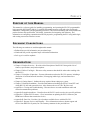
P URPOSE
OF THIS
M ANUAL
This manual is a reference guide for installing, programming, and operating the PLC033 programmable
logic controller (DFS-00507-008-01). It contains information meant to guide and assist you through
installation, configuration, and programming procedures. This includes mounting and wiring instructions,
product features and specifications, I/O listings, instructions for integrating with telemetry, and
information on configuring communication and I/O properties, programming the PLC using ladder logic,
and creating custom user interface screens.
D OCUMENT C ONVENTIONS
The following conventions are used throughout this manual:
Bulleted lists provide information, not procedural steps.
Numbered lists provide sequential steps or hierarchal information.
Italic type is used for emphasis
O RGANIZATION
Chapter 1: Product Overview – Provides a brief description of the PLC033 along with a list of
features, specifications, and pin descriptions.
Chapter 2: Before You Begin – Discusses safety measures that should be taken when working with
the PLC033.
Chapter 3: Principles of Operation – Presents information on how the PLC033 operates, including a
discussion of serial and network interfaces, I/O mapping, ladder logic, and customized user
interfaces.
Chapter 4: Getting Started – Outlines the steps required when setting up a system.
Chapter 5: Hardware Installation – Provides information on installing the PLC033 in an RTU and
wiring RS-232/-485 and network devices. Also discusses the use of a PLC By-Pass card.
Appendix A: Testing and Troubleshooting – Discusses how to test and troubleshoot radio and
network communication problems.
Appendix B: Application Notes – Describes how the PLC033 can be used to solve specific problems.
Appendix C: Update PLC Firmware – Gives instructions on updating the PLC’s firmware ((the
ROM-based software that controls the device).
Appendix D: Parts List– Provides a list of products available for use with the PLC033.
Appendix F: Support, Service, and Warranty – Gives information on how to obtain support and
service from Data Flow Systems, Inc. The warranty statement is also provided here.
1
Preface
A BBREVIATIONS U SED
IN THIS
M ANUAL
ACM – Analog Control Module
AMM – Analog Monitor Module
I/O – Input/Output
BEM – Bus Extender Module
DCM – Digital Control Module
DMM – Digital Monitor Module
LSB – Least Significant Bit
MBP – Modular Backplane
MSB – Most Significant Bit
NIM – Network Interface Module
PLC – Programmable Logic Controller
PMT – Process Management Toolkit
RIM – Radio Interface Module
RIO – Rail I/O (RIO128 with 128 I/O; RIO032 with 32 I/O)
RTU – Remote Terminal Unit
PLC033 Installation and Operation Manual
2
Chapter 1: PRODUCT OVERVIEW
D ESCRIPTION
The PLC033 is a microprocessor-controlled programmable logic controller designed for implementing
local logical control at the RTU via an installed ladder logic program. Users configure the PLC033’s I/O
and communication settings and create the ladder logic program using the applications included in the
supplied Process Management Toolkit (PMT) software.
The PLC033 must be installed in a specially-designed RTU – one with a modular backplane (MBP) that
has been modified to split the communications bus into two entities: the Radio Bus and the Module Bus.
The MBP is a printed circuit board composed of card edge connectors for the modules, module bus
circuitry, and a connection for the back-up battery. The PLC033, and all other DFS plug-in function
modules used in the system, are plugged into card edge connectors mounted on the RTU’s MBP.
In a typical installation, the PLC033 is installed between the RIM (Radio Interface Module) and up to 15
DFS function modules. The PLC033 uses the Radio Bus to communicate with the RIM and the Module
Bus to communicate with the DFS function modules. Once installed in the RTU, the PLC033
communicates with configured DFS function modules over the Module Bus, getting their status and
updating their outputs according to the ladder logic program. It communicates with the central site via
the RIM interface, relaying status and control information. It can also simulate “logical” analog and
digital modules to allow the PLC033’s program to interact with the SCADA system.
The PLC033 can emulate up to two RTUs. This allows developers to exceed the 15 module maximum
for DFS RTUs. This is accomplished by adding a remote device to PMT’s Radio Map and configuring
the remote device (station) in HyperTAC II. Refer to the Process Management Toolkit User Manual.
The PLC033 features an Ethernet port and a serial port (either RS-232 or RS-485) that can be used to
expand the PLC033’s functionality.
In addition to being the PLC033’s programming interface, the Ethernet port enables the PLC033 to
function as a network slave device using either DFS NIM RTU protocol or Modbus TCP protocol.
As a DFS NIM RTU slave, the PLC033 can be polled by a HyperTAC II central over the network. This
feature can be used simultaneously with radio polling, so that one RTU can be polled from two different
systems: one on the network and one over the radio link. Alternatively, the PLC033 can function solely
as a network device by placing an RS-232 RIM (RIM board without the radio installed) in the RTU and
polling the PLC033 from the HyperTAC II central using the DFS NIM protocol. There is no additional
configuration required to implement either of these functions.
As a Modbus TCP slave, the PLC033 can be polled by any Modbus-compatible software that uses the
Modbus TCP protocol.
Using the COM1 serial port, the PLC033 can function as a Modbus RTU/ASCII master or slave device.
As a Modbus master, the PLC033 can poll a single Modbus-compatible RS-232 device, or multiple
Modbus-compatible RS-485 devices via its COM1 serial port using either the Modbus RTU or ASCII
protocol. As a Modbus slave, the PLC033 can be polled by any Modbus-compatible software that uses
the Modbus RTU or ASCII protocols.
3
Chapter 1: Product Overview
Another important feature of the PLC033 is its ability to function as a PLC central. The PLC Central
feature enables the PLC033 to poll remote DFS RTUs in addition to local modules and local Modbuscompatible I/O. PLC Central can be a secondary function of the PLC033 or its primary function. The
PLC033’s mode is determined by the value of Special Function Register 9951, “Comm 2 DFS Central
Mode.” When the register is true, the PLC033 functions as a PLC central.
As a secondary function (limp, or backup, mode), the PLC033 can temporarily switch to PLC Central
mode when it determines that communications with the HyperTAC II central have been lost. This mode
uses two timers that are inserted in the PLC033’s ladder logic program that instruct the PLC033 when it
should switch to PLC Central Mode (Comm 2 DFS Central Mode is set to “true”) and when it should
return to normal operation (Comm 2 DFS Central Mode is set to “false”) to check if communications
with the HyperTAC II central have been restored.
For RTU systems that require a centralized site for logic, but aren’t large enough to warrant a HyperTAC
II central site, the PLC033 can be forced to permanently stay in PLC Central mode by setting and
keeping the Comm 2 DFS Central Mode register at a “true” value in the PLC033’s ladder logic program.
F EATURES
33 MIP ARM processor with 8M of Flash ROM and 16M of RAM
1200 or 9600 baud communications with TAC II devices
Up to 38.4 Kbps with external RS-232/RS-485 devices using Modbus RTU or ASCII protocol
PLC Central functionality
Modbus TCP and DFS NIM RTU-based communications via Ethernet interface
Real time clock for time of day functions
Monitors its own power source and saves accumulated data when a power failure is detected
Communicates with master or slave devices via serial port that can be used in RS-232 or -485 mode
Programmed using ladder logic (Logic Builder); Program stored in Non-Volatile memory
Communication and I/O parameters configured with user-friendly interface (I/O Builder)
Custom status and control screens can be created using supplied software (Screen Builder)
Shutdown button enables graceful shutdown of all PLC033 processes
Surge protected (nondestructive)
4 programmable LEDs and 8 hardware/firmware-controlled LEDs (power, module receive data,
module transmit data, radio receive data, radio transmit data, CPU failure, PLC033 status, and
network status).
On-board communications and functional firmware
On-board voltage regulation
Automatically retrieves data from modules on RTU bus
Module is removable without disturbing field wiring
Keyed to prevent damage
Time-tagged messages
Battery-backed clock/calendar synchronized by telemetry
No adjustments, switches or straps (self-configuring)
Watchdog timer
Gold edge connector fingers
PLC033 Installation and Operation Manual
4
Chapter 1: Product Overview
T ECHNICAL S PECIFICATIONS
Board size
Supply voltage
Supply current
Max. number of DFS
modules supported
Network Interface (1)
Serial Interface (3)
LEDs
Configuration bits
Protocols
5.25” X 6.88”
8 to 13 VDC
290 mA
15
10/100base-T
COM1 (RS-232 or RS-485 Modbus master or slave); COM2 (DFS Radio
Bus slave); COM3 (DFS Module Bus master)
Four programmable LEDs (DS9, DS10, DS11, and DS12); 8
hardware/firmware-controlled LEDs: power (PWR), module receive data
(MRX), module transmit data (MTX), radio receive data (RRX), radio
transmit data (RTX), CPU failure (FLT), PLC033 status (STAT), and
network status (LINK)
Five configuration bits for use in ladder logic programs
DFS, Modbus ASCII, Modbus RTU, and Modbus TCP
DFS-00507-011-01
5
Chapter 1: Product Overview
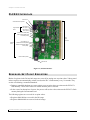
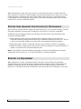
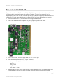
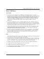
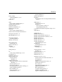
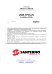
PLC033 I NTERFACE
Service Port
Shutdown/Power Up Button
Programmable
LEDs
LED 0 (DS12)
LED 1 (DS11)
LED 2 (DS10)
LED 3 (DS9)
Radio Receive Data (RRX)
Radio Transmit Data (RTX)
PLC Status (STAT)
Card
Edge
Connector
Defined
LEDs
CPU Failure (FLT)
Module Receive Data (MRX)
Module Transmit Data (MTX)
Power (PWR)
Network Status (LINK)
Ethernet Port
Figure 1-1, PLC033 Interface
R ESERVED S ET P OINT R EGISTERS
Blocks of registers in the DO and AO ranges are reserved for storing user set point values. Values stored
in these registers are automatically written (saved) to the PLC’s flash memory every 30 seconds. They
are also saved during a controlled shutdown.
During a controlled shutdown (see next section), user set point values are written to the PLC033’s
flash memory. These stored values are loaded when the process resumes.
In the event of an abrupt loss of power, the process will use the values written to the PLC033’s flash
memory during the last automated save.
The following registers are reserved for set point values:
Registers 9800-9899 are reserved in the DO range.
Registers 49800-49899 are reserved in the AO range.
PLC033 Installation and Operation Manual
6
Chapter 1: Product Overview
CONTROLLED SHUTDOWN
The following events initiate a controlled shutdown:
If voltage in the panel falls to 11.2 volts, the PLC033’s operating system will initiate the shutdown
without user intervention.
Press the shutdown button on the PLC033 to manually stop the process.
Use Special Function Registers – Remote Process Start Command (9920) and Remote Process Stop
Command (9921) – to shutdown the process from a remote location. For example, you could map
these registers to a DFS module point in the PLC’s DFS Radio Map and configure the same point in
HT3. The registers could then be controlled from a custom screen or a default screen.
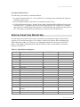
S PECIAL F UNCTION R EGISTERS
The following local and derived I/O points are provided as special function registers. Most of these
registers are for external status queries. For example, registers 9930 (Remote Process Running) and
49902 (Maximum Ladder Loop Time) give you important information on the status of the PLC033.
Others, such as 9900 (Configuration Bit 0) and 9910 (LED 0) can be used in ladders to control the
behavior of the PLC033.
Table 1-1, Special Function Registers
Address
Function
Ladder R/W
Remote R/W
9900
:
9905
:
9909
9910
9911
9912
9913
9920
9921
9930
9940
9941
9942
9943
9950
:
9957
Configuration Bit 0
:
Configuration Bit 5
:
General Input 9
Led 0 DS12
Led 1 DS11
Led 2 DS10
Led 3 DS9
Remote Process Start Command
Remote Process Stop Command
Remote Process Running
Global Alarm
Low Memory
Low Voltage
Local I/O Fault
Comm 1 DFS Central Mode
:
Comm 8 DFS Central Mode
R
:
R
:
R
RW
RW
RW
RW
R
R
RW
R
R
R
R
RW
:
RW
R
:
R
:
R
R
R
R
R
RW
RW
R
R
R
R
R
R
:
R
49900
Local Analog Input (Power Supply
Voltage)
OS Free Memory
Maximum Ladder Loop Time
R
R
R
R
R
R
49901
49902
DFS-00507-011-01
7
Chapter 1: Product Overview
Address
Function
Ladder R/W
Remote R/W
49903
49904
49905
49906
49907
49908
49909
49910
49911
49912
49913
49914
49915
49916
49917
49918
49919
49920
49921
49922
Average Ladder Loop Time
Minimum Ladder Loop Time
Maximum I/O Loop Time
Average I/O Loop Time
Minimum I/O Loop Time
Hardware Model
Hardware Revision
Software Version Year
Software Version Month
Software Version Day
OS Version Year
OS Version Month
OS Version Day
Serial Number High
Serial Number Low
Network Address Octet 4
Ladder Process ID
Ladder Process Version Year
Ladder Process Version Month
Ladder Process Version Day
R
R
R
R
R
R
R
R
R
R
R
R
R
R
R
R
RW
RW
RW
RW
R
R
R
R
R
R
R
R
R
R
R
R
R
R
R
R
R
R
R
R
49950
:
49957
Comm 1 Time Since Last Comm (secs)
:
Comm 8 Time Since Last Comm
RW
:
RW
R
:
R
49999
Remote Reset (data must be 0xA5A5)
R
RW
PLC033 Installation and Operation Manual
8
Chapter 1: Product Overview
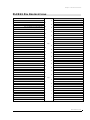
PLC033 P IN D ESCRIPTIONS
LOCAL MODULES SYSTEM DC VOLTAGE +
43
LOCAL MODULES SYSTEM GROUND
41
LOCAL MODULES /POWER DOWN /
39
LOCAL MODULES /REQUEST TO SEND /
37
LOCAL MODULES /CLEAR TO SEND /
35
LOCAL MODULES /RECEIVE DATA /
33
LOCAL MODULES /TRANSMIT DATA /
42
RIM SYSTEM DC VOLTAGE +
40
RIM SYSTEM GROUND
38
RIM /POWER DOWN /
36
RIM /REQUEST TO SEND /
34
RIM /CLEAR TO SEND /
32
RIM /RECEIVE DATA /
30
RIM /TRANSMIT DATA /
31
=key=
CFG GROUND
(JUMP PIN 27 TO 29 FOR DEBUG MODE)
29
CFG RUN/TRAP; 0FFFFH CONFIGURATION BIT 3 = (8)
27
CONFIGURATION BIT 2 = (4)
25
CONFIGURATION BIT 1 = (2)
23
CONFIGURATION BIT 0 = (1)
21
CONFIGURATION BIT 5 = (32)
19
CONFIGURATION BIT 4 = (16)
17
RS-485 B
15
28
26
24
22
20
18
16
14
RS-485 A
13
==
key
RS-485 SHIELD
11
HOST 232 CTS
9
HOST 232 RTS
7
HOST 232 GND
5
HOST 232 TXD
3
HOST 232 RXD
1
12
10
8
6
4
2
DFS-00507-011-01
9
Chapter 1: Product Overview
Notes
PLC033 Installation and Operation Manual
10
Chapter 2: BEFORE YOU BEGIN
S AFETY P RECAUTIONS
Review the following statements before installing, servicing, or replacing the PLC033 Programmable
Logic Control or any of its components.
G ENERAL P RECAUTIONS
Only trained and qualified personnel should install, service, or replace this equipment.
Carefully read the installation and wiring instructions before connecting the PLC033 to its power source.
Do not work on the PLC033, or connect or disconnect any of its cables, during periods of lightning
activity.
To prevent overheating the PLC033, do not operate it in an area that exceeds the maximum
recommended temperature range of 0OC (32OF) to 70OC (158OF).
Ensure that the unit is connected to earth ground during normal use.
Precautionary measures must be observed when installing, operating, and servicing the PLC033 in order
to prevent shock from voltages present.
If the PLC033 is to be installed into an existing control panel, make sure that all breakers are shut off
before starting the installation.
All wiring should conform to federal, state, and local electrical codes.
When using the PLC033, observe the following safety guidelines:
To help prevent electric shock, wire the PLC033 and peripheral power cables into properly grounded
power sources.
Be sure nothing rests on the PLC033’s cables and that the cables are not located where they can be
stepped on or tripped over.
W ORKING
WITH THE
PLC033
Before working with the PLC033 where the removal of components is necessary, perform the following
steps in the sequence indicated:
1. Power down the unit.
2. Turn off all circuit breakers to the PLC033.
3. Ensure that any cables connected to the PLC033 will not become entangled in or caught on anything
in the surrounding area.
11
Chapter 2: Before You Begin
When disconnecting a cable, pull on its connector or on its strain-relief loop, not on the cable itself.
Some cables have a connector with locking tabs; when disconnecting this type of cable, press in on the
locking tabs before disconnecting the cable. When pulling connectors apart, you should keep them
evenly aligned to avoid bending any connector pins. Also, before connecting a cable, make sure both
connectors are correctly oriented and aligned.
P ROTECTING A GAINST E LECTROSTATIC D ISCHARGE
Static electricity can harm delicate components inside the PLC033. To prevent static damage, put on an
electrostatic discharge wrist strap before touching any of the PLC033’s electronic components.
In addition to the preceding precautions, the following steps can be taken to prevent damage from
electrostatic discharge (ESD):
When unpacking a static-sensitive component from its shipping carton, do not remove the
component's antistatic packing material until ready to install the component in the PLC033. Be sure
to put on an electrostatic discharge wrist strap before unwrapping the antistatic packaging.
When transporting a sensitive component, first place it in an antistatic container or packaging.
Handle all sensitive components in a static-safe area. Place the equipment on a grounded surface. If
possible, use antistatic floor pads and workbench pads.
Note: Contact DFS if electrostatic discharge packaging is needed for return shipments. See Return
Authorization (RA) Procedure, p. 53 for more information on returning equipment.
R ECEIPT
OF
E QUIPMENT
When equipment is received, examine the outside of the carton for any damage incurred during
shipment. Remove the packing list and the equipment from the shipping carton. Carefully inspect the
equipment for damage. Resolve any damage with the local carrier. Report damages to Data Flow
Systems (321-259-5009). Include the serial number of the unit and the extent of damage in your report.
PLC033 Installation and Operation Manual
12
Chapter 3: PRINCIPLES OF OPERATION
The PLC033 is a powerful programmable logic controller that can be installed in a DFS Remote
Terminal Unit (RTU). This microprocessor-controlled unit is designed for implementing local logical
control at the RTU via an installed ladder logic program. Users configure the PLC033’s I/O and
communication settings and create the ladder logic program using the applications included in the
supplied Process Management Toolkit (PMT) software.
I NSTALLED
IN
S PECIALLY - DESIGNED RTU
The PLC033 must be installed in a specially-designed RTU – one with a modular backplane (MBP) that
has been modified to split the communications bus into two entities: the Radio Bus and the Module Bus.
The MBP is a printed circuit board composed of card edge connectors for the modules, module bus
circuitry, and a connection for the back-up battery. The PLC033, and all other DFS plug-in function
modules used in the system, are plugged into card edge connectors mounted on the RTU’s MBP.
L OGICAL I/O
The PLC033 itself doesn’t have any physical I/O; it is strictly a programmable device that polls external
I/O and responds to polls from a central site, and then performs logic on this data using an installed
ladder logic program.
The PLC033 polls the I/O on the Module Bus (i.e., up to 15 local DFS function modules) as well as the
I/O of any Modbus-compatible devices connected to the PLC033’s COM1 port. The COM1 port can be
used in either RS-232 or RS-485 mode, which enables it to support a single RS-232 device, or multiple
RS-485 devices. The PLC033 can communicate with these devices using either Modbus ASCII or
Modbus RTU protocol.
T YPICAL I NSTALLATION
In a typical installation, the PLC033 is installed between the RIM (Radio Interface Module) and up to 15
DFS function modules. The PLC033 uses the Radio Bus to communicate with the RIM and the Module
Bus to communicate with the DFS function modules. Once installed in the RTU, the PLC033
automatically communicates with the other DFS function modules over the Module Bus, getting their
status and updating their outputs according to the ladder logic program. It communicates with the central
site via the RIM interface, relaying status and control information. It can also simulate “logical” analog
and digital modules to allow the PLC033’s program to interact with the SCADA system.
13
Chapter 3: Principles of Operation
E MULATE M ULTIPLE DFS RTU S
The PLC033 can emulate up to two RTUs. This allows developers to exceed the 15 module maximum
for DFS RTUs. This is accomplished in PMT’s Mapper by right-clicking the main branch of the Radio
Map and selecting “Add Remote Device.” This remote device can accommodate up to 15 DFS modules.
The Remote Device Number should be the next station number after the physical address of the station
the PLC is installed in (for example, if the PLC is in RTU #17 then add remote device #18 in the Radio
Map.
When configuring the remote device (emulated station) In HyperTAC II, the remote device’s RIM type
should be configured as a RIM004. The station number in HyperTAC II must match that configured for
the remote device in PMT.
For more information, refer to the section titled “Adding a Remote Device (Emulated DFS RTU)” in the
Process Management Toolkit User Manual.
PLC C ENTRAL
Another important feature of the PLC033 is its ability to function as a PLC central. The PLC Central
feature enables the PLC033 to poll remote DFS RTUs in addition to local modules and local Modbuscompatible I/O. PLC Central can be a secondary function of the PLC033 or its primary function. The
PLC033’s mode is determined by the value of Special Function Register “Comm 2 DFS Central Mode.”
When the register is true, the PLC033 functions as a PLC central.
As a secondary function (limp, or backup, mode), the PLC033 can temporarily switch to PLC Central
mode when it determines that communications with the HyperTAC II central have been lost. This mode
uses two timers that are inserted in the PLC033’s ladder logic program that instruct the PLC033 when it
should switch to PLC Central Mode (Comm 2 DFS Central Mode is set to “true”) and when it should
return to normal operation (Comm 2 DFS Central Mode is set to “false”) to check if communications
with the HyperTAC II central have been restored.
For RTU systems that require a centralized site for logic, but aren’t large enough to warrant a HyperTAC
II central site, the PLC033 can be forced to permanently stay in PLC Central mode by setting and
keeping the Comm 2 DFS Central Mode register at a “true” value in the PLC033’s ladder logic program.
This function is discussed in more detail in Appendix B: Application Notes in the section titled
“Implement PLC Central Function” beginning on page 43.
S ET P OINT V ARIABLES (Q P OINTS )
Q points, named as such because they always reside at module address Q in HyperTAC II’s
Configuration Editor, are used to create user set point variables beyond the PLC’s 15-module limit. Q
points allow you to access and use the PLC’s 168 free (unused) memory locations.
Q points are non-scaled, 32-bit floating point values that are readable and writable over telemetry via
DFS radio or network (NIM) protocol. The Q point registers reside in the 49000 range beginning at
register 49464 and ending at register 49798. Because Q points are 32-bit floating point values, each point
PLC033 Installation and Operation Manual
14
Chapter 3: Principles of Operation
requires two registers; each Q point begins on an even register (e.g., Q point number 50 resides at
registers 49562 and 49563).
Q points do not have to be configured in I/O Builder. The 168 Q points are automatically added to the
Logical Memory Map when a PLC project is created. Each point is given a label that begins with the
letter Q (e.g., Q1, Q2, Q3, etc.). Additionally, they do not have to be mapped from the Logical Memory
Map into the DFS Radio Map. Q points are mapped internally and respond to specially-formatted
messages sent from HyperTAC II. Like other I/O, Q points can be used in ladders and in custom screens.
It is important to note that Q points are not designed to be used as status points. In HyperTAC II, they are
not polled as often as “normal” I/O; doing so would negatively impact the polling loop. However, as a set
point variable, the control is acted on immediately.
To add Q points to an existing PLC project, you must chang the project type to RDP and then change it
back to PLC. If you have I/O in the Logical Memory Map that is mapped to the registers assigned to Q
points, they will not be overwritten. The Q points will be placed “around” the taken registers and will
always start at an even register number.
Like the reserved set point registers set aside for storing user set point values (discussed on page 6),
Q Point values are automatically saved to the PLC033's flash memory every 30 seconds and also during a
controlled shutdown. These stored values are loaded when the process resumes.
N ETWORK S LAVE D EVICE
In addition to being a programming interface, the PLC033’s Ethernet port enables it to function as a
network slave device using either DFS NIM RTU protocol or Modbus TCP protocol.
As a DFS NIM RTU slave, the PLC033 can be polled by a HyperTAC II central over the network. This
feature can be used simultaneously with radio polling, so that one RTU can be polled from two different
systems: one on the network and one over the radio link. Alternatively, the PLC033 can function solely
as a network device by placing an RS-232 RIM (RIM board without the radio installed) in the RTU and
polling the PLC033 from the HyperTAC II central using the DFS NIM protocol. There is no additional
configuration required to implement either of these functions. The PLC033 will automatically respond to
network queries as well as radio requests if the DFS Radio Map is configured (explained in more detail
in “I/O Mapping” on page 16). Note that the DFS NIM RTU interface uses the radio map; there is not a
separate map for using network communications.
As a Modbus TCP slave, the PLC033 can be polled by any Modbus-compatible software that uses the
Modbus TCP protocol.
The PLC033 requires its own unique network IP address in order for it to be polled over the network.
Refer to the section titled PLC Network Settings” in Chapter 5: Hardware Installation beginning on page
27, as well as the Process Management Toolkit User Manual, for more information on PLC033 IP
addressing.
DFS-00507-011-01
15
Chapter 3: Principles of Operation
M ODBUS S ERIAL M ASTER /S LAVE D EVICE
The PLC033 can function as a Modbus RTU/ASCII serial master or slave device via its COM1 serial
port. As a Modbus serial master, the PLC033 can poll a single Modbus-compatible RS-232 device, or
multiple Modbus-compatible RS-485 devices via its COM1 serial port using either the Modbus RTU or
ASCII protocol. As a Modbus serial slave, the PLC033 can be polled by any Modbus-compatible
software that uses the Modbus RTU or ASCII protocols.
When configuring this port (i.e., Modbus driver) in PMT’s Configuration Editor, you must select either
SERIAL_MASTER or SERIAL_SLAVE for the TYPE option. Configuration Editor will only allow the
addition of devices and I/O under a Modbus driver when TYPE is set to SERIAL_MASTER. When this
port has been configured as a serial slave, it cannot be used as a serial master. The functionality of this
port is not switchable as is the PLC Central feature. The port’s function can only be modified by
changing the TYPE setting.
S UPPORTS M ULTIPLE P ROTOCOLS
At its core, the PLC033 is a Modbus device. Modbus is an industry-standard protocol and as such
enables the PLC033 to communicate with any third-party Modbus devices, including Open Control
Solutions’ RIO128 and RIO032 rail-mounted I/O devices. The PLC033 is able to support both DFS and
Modbus protocols through a process called mapping. In mapping, each physical I/O point is assigned to a
unique register in the PLC033’s Logical Memory Map. The Logical Memory Map is comprised of four
register ranges:
I/O Type
Register Range
Digital Outputs (Coils)
00001-09999
Digital Inputs (Discrete Inputs)
10001-19999
Analog Inputs (Input Registers)
30001-39999
Analog Outputs (Holding Registers)
40001-49999
I/O M APPING
The physical I/O of local DFS function modules as well as the I/O of any external Modbus-compatible
devices must be mapped. This ensures that there are no duplicate, or conflicting, addresses. Once
mapping is complete, these registers are available for use in ladders and custom screens. When doing this
type of mapping, you need to be aware of the registers that have been set aside for special functions (for
example, controlling the four programmable LEDs) and the registers reserved for set points. A list of
these registers can be found in Chapter 1: Product Overview.
A second form of mapping, DFS Radio mapping, is required in order for the PLC033 to be polled by a
HyperTAC II system. In this process, the registers in the Logical Memory Map are mapped to up to 30
DFS modules [up to 15 modules per station with a two (2) station maximum]. For example, registers in
the 00001-09999 range (digital outputs) would be mapped to one or several Digital Control Modules
(DCM003); registers in the 40001-49999 range (analog outputs) would be mapped to one or several
PLC033 Installation and Operation Manual
16
Chapter 3: Principles of Operation
Analog Control Modules (ACM002). The mapped I/O can be any combination of physical I/O, logical
I/O generated by ladder programs, and special function registers.
Because the DFS radio link uses a 12-bit protocol with a full-scale output of 4095, you must specify how
you want to shift the bits in the register when working with any data that is greater than 12 bit that will be
sent over the DFS radio link (for example, 15-bit RIO128 data or 16-bit logical data). Details on this
process can be found in the section titled “DFS Radio Mapping: Register (Bit) Shifting Options” in the
Process Management Toolkit User Manual.
P ROGRAMMING I NTERFACE
The PLC033’s Ethernet port is its interface to the Process Management Toolkit (PMT), a suite of
applications used to configure, program, and test the PLC033.
When interfacing with the PMT, the PLC033 can be accessed using a “closed” network. This is
accomplished by directly connecting the PLC033 to a laptop or desktop computer using an Ethernet
crossover cable. With a closed network, the PLC033’s network settings can be left at the default IP
address of 192.168.1.10.
Note that if the PLC033 is going to be configured, programmed, or polled over the network, it requires
its own unique network IP address.
More information on PLC IP addressing can be found in Chapter 5: Hardware Installation in the section
titled PLC Network Settings” beginning on page 27, as well as in the Process Management Toolkit User
Manual.
P ROGRAMMED
WITH
L ADDER L OGIC
The PLC033 is programmed using Logic Builder, a user-friendly application that enables you to
construct "ladder logic"-style programs that manage complex control functions. Ladder logic is a
graphical (symbols and text) language that is used to plan, maintain and control industrial systems. Each
rung of the ladder (hence the name - ladder logic) is used to control a single output.
The results of these graphical programs are logical points and auto controls that are continuously scanned
by the system. The speed of the scanning process enables you to have the most up-to-date information,
which, in turn, allows you to react to situations quickly and efficiently.
In traditional ladder logic, the values that flow along rungs and branches are strictly logical, 0 or 1. DFS'
Logic Builder provides the extra flexibility of allowing rungs and branches to hold numeric values (for
example, the results of math operations, such as ADD and MAXIMUM, and inputs from analog points).
After a ladder logic program has been built and installed, its logical points and auto controls can be used
in custom screens (graphical representations of your process control system) that can be used to remotely
monitor and control your system.
DFS-00507-011-01
17
Chapter 3: Principles of Operation
M ONITOR
AND
C ONTROL
C USTOM S CREENS
VIA
Graphical representations of your process control system can be created using the Screen Builder
application. Building a screen – using text, images, objects, and animation – and linking the screen's
components to real or logical I/O, enable you to get a real-time view of your operation as well as control
processes from a remote location.
For example, you can build a screen that shows the flow of a pump or the level in a well, and then use the
device's address (register) to link it to the real field hardware. This linking lets you create a virtual picture
of how the equipment is operating; the screen mimics the activity of the equipment. It also enables you to
control devices from a remote location. For example, a screen with an On/Off button that is linked to a
pump motor can be used to start or stop a pump.
C ONTROLLED S HUTDOWN
The following events initiate a controlled shutdown:
If voltage in the panel falls to 11.2 volts, the PLC’s operating system will initiate the shutdown
without user intervention.
Press the shutdown button on the PLC to manually stop the process.
Use Special Function Registers – Remote Process Start Command (9920) and Remote Process Stop
Command (9921) – to shutdown the process from a remote location. For example, you could map
these registers to a DFS module point in the PLC’s DFS Radio Map and configure the same point in
HT3. The registers could then be controlled from a custom screen or a default screen.
PLC033 Installation and Operation Manual
18
Chapter 3: Principles of Operation
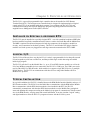
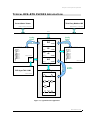
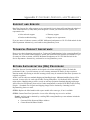
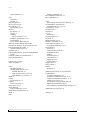
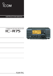
T YPICAL DFS-RTU PLC033 A PPLICATION
Screen/Status Viewer
Third-Party Modbus HMI
Modbus TCP Protocol (no map required)
Modbus TCP Protocol
C
a
t
5
(no map required)
C
a
t
5
Network
C
a
t
5
Config
Editor
Config
Editor
PLC033
00000...
DO
...09999
1-bit wide
10001...
DI
DFS Radio Map
Module A
Point 1
Point 2
Point 3...
Module B
Point 1
Point 2
Point 3...
Module C...
DFS TAC II I/O Modules
...19999
1-bit wide
Serial Bus
30001...
AI
DFS TAC II Protocol
RIM
R
a
d
i
o
...39999
16-bit wide
40001...
Serial Bus
AO
DFS TAC II Protocol
...49999
16-bit wide
Modbus Registers
I
P
C
DFS HyperTAC II HMI
Module A
Point 1
Point 2
Point 3...
Module B
Point 1
Point 2
Point 3...
Module C...
Ladder Logic
Logic
Builder
DFS TAC II Protocol
V
31762
40097
P
30854
V
41375
A
38293
V
07642
00089
06432
Figure 3-1, Typical PLC033 Application
DFS-00507-011-01
19
Chapter 3: Principles of Operation
Notes
PLC033 Installation and Operation Manual
20
Chapter 4: GETTING STARTED
1. Define the problem. What problem are you trying to solve by installing the PLC? What kind of I/O
do you need? What do you need to monitor and control in the field? What information needs to be
sent back to the central computer?
2. Install the PLC and all related hardware. Discussed in Chapter 5: Hardware Installation
3. Create a new project in the Project Management Toolkit and define the basic settings, including IP
address and mode (PLC or RDP). Discussed in the Process Management Toolkit User Manual.
4. Define ranges for the physical I/O, user-defined logical I/O (for example, virtual analog inputs and
outputs you create in Logic Builder), and the logical I/O generated internally by Logic Builder. Be
aware that the high end of the digital output and analog output ranges are reserved for user set points
and special functions (see Chapter 1: Product Overview for more information).
We recommend the following:
Range Type
Digital Outputs
Digital Inputs
Analog Inputs
Analog Outputs
Physical I/O
1-1000
10001-11000
30001-31000
40001-41000
User-defined
Logical I/O
1001-1999
11001-11999
31001-31999
41001-41999
System-generated
logical I/O
2000-9799
12000+
32000+
42000-49799
Reserved set point
registers
9800-9899
---
---
49800-49899
Special Function
Registers
9900+
---
---
49900+
5. Add and configure the physical I/O using I/O Builder. Discussed in the Process Management
Toolkit User Manual.
6. Map the physical I/O into the appropriate register ranges using the Register Map. Discussed in the
Process Management Toolkit User Manual.
7. Transfer the mapped I/O to the PLC. Discussed in the Process Management Toolkit User Manual.
8. Create a ladder logic program that can locally control the hardware (monitor status, make decisions,
perform calculations, etc.). Install the ladder in temporary memory during testing. When everything
is working correctly, flash it to permanent memory. Discussed in the Process Management Toolkit
User Manual.
9. Map logical I/O into the DFS Radio Map and transfer it to the PLC. Note that it isn’t necessary to
map all of the logical I/O; only the I/O that will be sent over the radio link. Discussed in the Process
Management Toolkit User Manual.
10. Create custom screens that enable users to view the status of equipment or control set points.
Discussed in the Process Management Toolkit User Manual.
21
Chapter 4: Getting Started
Notes
PLC033 Installation and Operation Manual
22
Chapter 5: HARDWARE INSTALLATION
I NSTALLING
THE
PLC033
IN THE
RTU
The PLC033 must be installed in a specially-designed DFS RTU. In a PLC-capable RTU, the modular
backplane (MBP) has been modified to separate the signals that go between the PLC033 and the Radio
Interface Module (RIM) (referred to as the Radio Bus), and the PLC033 and the local function modules,
including modules in a separate enclosure connected with BEM001s (referred to as the Module Bus).
The hardware installation of a PLC module into an RTU is slightly different than that of a regular I/O
function module. Any LOCAL modules (including modules in a separate enclosure connected with
BEM001s) that need to be monitored or controlled by the PLC must be connected to the communications
bus of the PLC, but separated from the communications bus of the Radio Interface Module (RIM). The
PLC033 (and all other modules installed in the RTU’s modular backplane) get their power from the
RTU’s power supply module via the bus.
The PLC033 is wired into an RTU, typically between the Radio Interface Module (RIM) and up to 15
other local modules. Normally, the PLC033 is located in the slot just to the left of the RIM, and only one
PLC033 may reside in each RTU. Consult DFS Engineering personnel for proper integration information
if variations to this standard installation are required.
IMPORTANT: The RIM used in a PLC033 RTU must be a RIM006 model and have a ROM version of
12/08/05 or later unless the PLC033 will be communicating solely over the network in which case an
RS-232 RIM (RIM without a radio installed) is placed in the RIM slot.
For a PLC033 using the DFS radio link, if the RIM doesn’t meet the specifications outlined above, no
communications will take place between the PLC033 and the radio.
The RIM will appear to be locked in transmit mode when observing its transmit LED (the LED will be
constantly on). Additionally, abort messages will appear when radio traffic is monitored using
HyperTAC II’s Telemetry Traffic Tool.
Instructions for determining ROM level appear on the next page. If you find that you’re RIM is not at
version 12/08/05 or later, contact DFS’ Service Department for information on upgrading.
23
Chapter 5: Hardware Installation
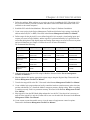
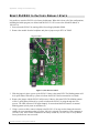
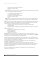
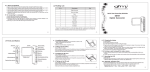
C HECKING R ADIO ’ S ROM V ERSION
As discussed above, the RIM used in a PLC033 RTU must be a RIM006 and must have a ROM version
of 12/08/05 or later. There are several ways to check the ROM’s version.
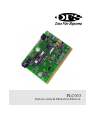
CHECK THE ROM LABEL
You can find the ROM version listed on a label attached to the radio’s ROM chip. Simply remove the
RIM’s cover plate to verify the version number. Refer to the illustration below for the location of the
label.
Figure 5-1, ROM Label on Radio Interface Module (RIM)
PLC033 Installation and Operation Manual
24
Chapter 5: Hardware Installation
USE WINRTU TEST
A RIM in the field or one that is set up on a test bench can be queried using WinRTU Test.
1. Connect a laptop or desktop computer that has WinRTU Test installed to the RIM’s service port
using the cable provided with WinRTU Test.
2. Launch WinRTU Test.
3. Set WinRTU’s communication settings by selecting Comm from the Config menu.
For Port, select the serial port on the computer to which the RIM is connected. Select 1200 for baud
rate. Verify that data bits is set to 7, parity is set to Odd, and stop bits is set to 2. Click OK.
4. Select ROM Patch from the Form menu. Click Query.
Messages will appear in the Tx and Rx fields as WinRTU Test begins communicating with the RIM.
After a few seconds, the Model number, serial number, and Current ROM will appear in the form.
Verify that the model is a RIM006 and the Current ROM is 12/08/05 or later.
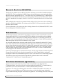
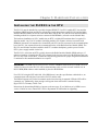
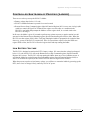
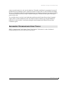
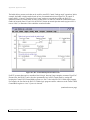
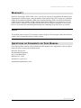
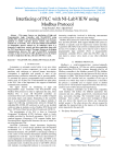
USE HYPERTAC II’S TELEMETRY TRAFFIC TOOL
If the RTU is online and can be accessed via telemetry, you can launch HyperTAC II’s Telemetry
Traffic tool and query the station for its version.
1. Enter the RTU’s station number in the Station box and enter R in the module box.
2. Click Start to begin communicating with the station.
3. When you see that messages are being received from the station (green messages), click the
Version button. You should see a blue message requesting version (“Message: Requesting
DFS-00507-011-01
25
Chapter 5: Hardware Installation
version for X R”, where X represents the station number). Shortly thereafter you should see a
response (“Reply {0XRr RIM006 12/08/05}”, where X represents the station number.
Figure 5-2, Check Radio ROM Version from HyperTAC II
PLC B Y -P ASS C ARD
The PLC By-Pass Card may be used in order to test basic module polling and control/status wiring of the
modules in an RTU configured for use with a PLC. The PLC By-Pass Card is a static hardware device
that allows the communications bus of the RIM to be reconnected to the module communication bus.
Once the By-Pass Card is installed into the PLC card edge connector, the RTU will function identical to
that of a standard RTU (i.e., an RTU with the I/O modules connected directly to the RIM).
Refer to the WinRTU Test Manual for testing basic control and status signals wired into DFS function
modules.
N ETWORK I NTERFACE
The PLC033 features a 10/100base-T network interface. This Ethernet port is used when configuring and
programming the PLC. In addition to being the PLC033’s programming interface, the Ethernet port
enables the PLC033 to function as a network slave device using either DFS NIM RTU protocol or
Modbus TCP protocol. A standard network crossover cable with RJ-45 connectors is all that is needed in
most cases to connect the PLC to a computer. However, if the PLC is going to stay on the network
permanently, we recommend that you install a 100Base-T Network Surge Arrestor, which can be ordered
from Data Flow Systems (DFS Part No. 002-0279).
PLC033 Installation and Operation Manual
26
Chapter 5: Hardware Installation
PLC N ETWORK S ETTINGS
The PLC must be on a network – either a local area network (LAN) or a closed network – to be
configured and programmed.
When a PLC leaves the factory, it is set to a default IP address of 192.168.1.10. PLCs that will be using a
radio link to communicate can be left at this default setting. However, if a PLC is going to be a network
device, your network administrator must assign it a unique network IP address. The PLC is configured
with this assigned “destination” IP address via the Settings dialog box in the Process Management
Toolkit (select File from the Settings menu). If the PLC isn’t going to be a network device, leave the
destination IP at the factory default setting.
A second IP setting – the Target IP (select File from the Process Management Toolkit’s Target menu) –
is only used when installing and retrieving configurations. The Target IP is the PLC’s current IP. For a
PLC that has just arrived from the factory, the Target IP is 192.168.1.10 (the factory default). For a PLC
that has been configured, the Target IP will be the IP specified in the Settings dialog. Note that if the
PLC hasn’t been used as a network device, then the destination IP (the address specified in the Settings
dialog) is the factory default 192.168.1.10 unless this was changed by someone configuring the PLC.
Normally, the IP addresses specified in Target and Settings will be identical. However, when you are
first setting up a network-bound PLC, the IP addresses will be different. In the Settings dialog, you will
enter the IP that you network administrator assigned to the PLC (its “destination” IP). In the Target
dialog, you will enter the PLC’s current IP – the factory default 192.168.1.10. This allows you to tell the
PLC what its IP address will be while communicating with the PLC using its current (Target) IP address.
Another scenario where the Target and Settings IP could be different is if you needed to move the PLC to
another IP address on your network. You would set the Target IP equal to the PLC’s current address and
then provide the PLC with its new destination IP address via the Settings dialog.
M ODBUS S ERIAL M ASTER /S LAVE I NTERFACE
The PLC033 features three serial ports. One of these, COM1, can be used in either RS-232 or RS 485
mode to communicate with external serial master or slave devices. The PLC033 can communicate with
these devices using either Modbus ASCII or Modbus RTU protocol. When used as a Modbus serial
master, the PLC033 can support a single RS-232 slave device or multiple RS-485 slave devices.
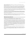
For RS-232 mode, use pins 1, 3, 5, 7, and 9; For RS-485 mode use Pins 11, 13, and 15.
Review the drawings below and on the next page before connecting a device to the COM1 part.
IMPORTANT: Do not use the PLC’s RS-232 service port when connecting to a serial master or slave
device. The service port is for use by DFS personnel only.
DFS-00507-011-01
27
Chapter 5: Hardware Installation
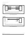
RS-232
M
O
D
B
U
S
9
CTS
D
E
V
I
C
E
CTS
7
RTS
RTS
5
GND
GND
3
TXD
TXD
1
RXD
RXD
P
L
C
0
3
3
NOTES:
1. RTS (request to send) and CTS (clear to send) connections are required to enable hardware flow control.
2. If a 3-wire interface is required, jumper RTS to CTS on both ends of the cable.
Figure 5-3, Wiring RS-232 Interface
RS-485
M
O
D
B
U
S
15
B
D
E
V
I
C
E
13
A
B
A
P
L
C
0
3
3
NOTES:
1. The cable shield wire must only be grounded at one end (as close as possible to the selected end).
2. Requires 150-200 ohm resistor (resistors should only be placed at the extreme ends of the RS-485 network).
Figure 5-4, Wiring RS-485 Interface
PLC033 Installation and Operation Manual
28
Appendix A: TESTING AND TROUBLESHOOTING
N O C OMMUNICATION
TO
F UNCTION M ODULES
If you are having problems communicating from the PLC033 down the bus to the function modules, you
can perform a “data tap” to determine if the problem is hardware related. A data tap is performed using a
standard Telnet connection. It enables you to view outgoing and incoming messages from the PLC
master to the modules. If messages are going out from the PLC033 to the function modules, but no
messages are coming in, the problem may lie with the module bus or with the module itself.
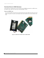
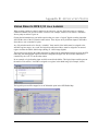
1. Open a Telnet connection by selecting Run from the Windows Start menu and typing
telnet xxx.xxx.xxx.xxx 504
Where xxx.xxx.xxx.xxx is the PLC’s IP address followed by 504 (the network port for this Telnet
application). If you are using a closed network to connect to the PLC033 (crossover cable between
the PLC033 and the computer), change the network settings for your computer so that it is on the
same network as the PLC. For example, if the PLC was at the factory default IP (192.168.1.10), you
could set your computer to 192.168.1.101 and telnet to 192.168.1.10.
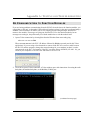
2. Click OK to open a Telnet connection. A Telnet window opens with instructions for testing the radio
backplane, the module backplane, or the Modbus (COM1) port.
(continued on next page)
29
Appendix A: Testing and Troubleshooting
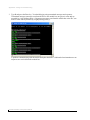
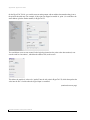
3. Type B and press the Enter key. You should begin seeing transmitted messages and responses.
Transmitted messages (messages sent from the PLC to the module bus) are green in color and are
preceded by a left-pointing carat (<). Responses (messages sent from the module bus to the PLC) are
white in color and are preceded by a right-pointing carat (>).
A problem communicating with the module backplane hardware is indicated when intermittent or no
responses are received from the module bus.
PLC033 Installation and Operation Manual
30
Appendix A: Testing and Troubleshooting
N O C OMMUNICATION
TO
RS-232/485 M ODBUS D EVICES
If you are having problems communicating from the PLC033 to RS-232 or -485 Modbus-compatible
devices, you can perform a “data tap” to determine if the problem is hardware related. A data tap is
performed using a standard Telnet connection. It enables you to view outgoing and incoming messages
from the PLC master to the Modbus-compatible devices. If messages are going out from the PLC033 to
the devices but no messages are coming in, the problem may lie with the configurations (Were they
uploaded to the PLC? Are they correct?), the connection to the device (Is it connected properly? Is the
cable damaged?), or with the device itself.
1. Open a Telnet connection by selecting Run from the Windows Start menu and typing
telnet xxx.xxx.xxx.xxx 504
Where xxx.xxx.xxx.xxx is the PLC’s IP address followed by 504 (the network port for this Telnet
application). If you are using a closed network to connect to the PLC033 (crossover cable between
the PLC033 and the computer), change the network settings for your computer so that it is on the
same network as the PLC. For example, if the PLC was at the factory default IP (192.168.1.10), you
could set your computer to 192.168.1.101 and telnet to 192.168.1.10.
2. Click OK to open a Telnet connection. A Telnet window opens with instructions for testing the radio
backplane, the module backplane, or the Modbus (COM1) port.
(continued on next page)
DFS-00507-011-01
31
Appendix A: Testing and Troubleshooting
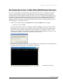
3. Type M and press the Enter key. You should begin seeing transmitted messages and responses.
Transmitted messages (messages sent from the PLC to the COM1 Modbus port) are green in color
and are preceded by a left-pointing carat (<). Responses (messages sent from the COM1 port to the
PLC) are white in color and are preceded by a right-pointing carat (>).
A problem communicating with the COM1 port hardware is indicated when intermittent or no
responses are received from the module bus.
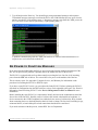
N O P OWER
TO
F UNCTION M ODULES
If you notice that the PSM, RIM, and PLC are powered, but the function modules downstream of the
PLC are not powered, the problem is probably due to the module bus fuse on the PLC033.
The PLC033 is equipped with two fuses that control power along the bus. One fuse is for incoming
power from the PSM side of the bus. The second fuse is for power to the module side of the bus.
This is a factory repair. See Appendix F: Support, Service, and Warranty for information on the
procedure for returning the PLC033 to DFS for repair.
If you have a spare PLC033 on site, you can replace the faulty PLC033. Before replacing the PLC033,
download its configurations into the PMT software, so they can be uploaded to the spare. See “Retrieve
Information from an Existing PLC033” in the Process Management Toolkit User Manual for more
information.
Before installing the spare PLC033, it is important to identify and correct the condition that caused the
fuse to blow in the first PLC. Possible causes of a blown fuse include a bad module or backplane. A
device connected to the 12VDC backplane bus could also be the source of a blown fuse. Keep in mind
when connecting devices to the backplane bus that it is fused at 10amp. The fuse itself, including its age,
an internal defect, or heat build up due to bad connections should also be considered.
If you need assistance with this process, contact DFS’ Service Department.
PLC033 Installation and Operation Manual
32
Appendix A: Testing and Troubleshooting
RIM L OCKED
IN
T RANSMIT M ODE
The RIM used in a PLC033 RTU must be a RIM006 model and have ROM code version 12/08/05 or
newer installed. If the RIM doesn’t meet these specifications, no communications will take place
between the PLC033 and the radio.
The RIM will appear to be locked in transmit mode when observing its transmit LED (the LED will be
constantly on). Additionally, abort messages will appear when radio traffic is monitored using
HyperTAC II’s Radio Traffic Tool.
To verify that the RIM has the latest ROM code installed, use HyperTAC II’s Radio Traffic Tool to
query the RIM for its version. The version must be 12/08/05 or later. If you have an older version of
ROM code, contact DFS’ Service Department to arrange an upgrade.
C ONNECTION R EFUSED
If you receive a “connection refused” error when trying to connect to a PLC033 from the Process
Management Toolkit (PMT), first verify that the correct IP was entered in the Target (File -> Target)
and Settings (File -> Settings) dialog boxes and that you can ping the IP.
If the IP address is correct and the ping was successful, the issue may be caused by personal firewall
software installed on your computer. If a firewall is present, you must either add the PMT software to the
firewall’s list of approved programs or add the IP address of the PLC033 to the list of trusted networks.
Without these settings, the firewall may not allow Java – the language on which PMT is built – to
connect to the PLC033’s IP address.
DFS-00507-011-01
33
Appendix A: Testing and Troubleshooting
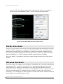
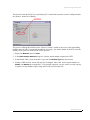
B ROADCAST PLC033 IP
If you need to find out the IP address to which the PLC033 is set, you can have it broadcast the IP and
view the results in a terminal program such as Hyper Terminal. This may be necessary if you’ve
forgotten the PLC033’s IP. The only solution in that case is to either have the PLC033 broadcast its IP or
reset the PLC033 to its factory default state (see Reset PLC033 to Factory Default State on page 36).
1. Power down the PLC033 by turning off the Power Supply Module (PSM).
2. Remove the module from the backplane and place a jumper on pin JP7 FACTORY.
PIN JP7 FACTORY
3. Using a service cable, connect a laptop to the PLC033’s service port.
4. Start a terminal program session (e.g., Hyper Terminal).
Bits per second = 38400
Data bits = 8
Parity = None
Stop bits = 1
Flow control = None
5. With the jumper in place, power up the PLC033. Observe the status LED. The blinking pattern will
be 8 quick flashes followed by a pause to indicate the PLC033 has been started in reset mode.
(continued on next page)
PLC033 Installation and Operation Manual
34
Appendix A: Testing and Troubleshooting
IMPORTANT: Do not remove the jumper while the PLC033 is powered. This will result in the PLC033
being reset to its factory default state. All configurations will be deleted and the IP address will be reset
to 192.168.1.10.
6. The PLC033’s IP address should be displayed on the terminal program’s screen along with the
message “Reset to Factory Default on Jumper Removal.”
7. When the PLC033’s IP address has been verified, power down the PLC033 and then remove the
jumper.
DFS-00507-011-01
35
Appendix A: Testing and Troubleshooting
R ESET PLC033
TO
F ACTORY D EFAULT S TATE
It is possible to reset the PLC033 to its factory default state. When this is done, all of the configurations,
including the ladder program, are deleted and the PLC033’s IP is reset to the default IP address of
192.168.1.10.
1. Power down the PLC033 by turning off the Power Supply Module (PSM).
2. Remove the module from the backplane and place a jumper on pin JP7 FACTORY.
PIN JP7 FACTORY
Figure 5-5, Pin JP7 FACTORY
3. With the jumper in place, power up the PLC033. Observe the status LED. The blinking pattern will
be 8 quick flashes followed by a pause to indicate the PLC033 has been started in reset mode.
4. Remove the jumper with the PLC033 still powered. Observe the status LED. The blinking pattern
will be 5 quick flashes followed by a pause to indicate the PLC033 is going through the reset
process. The LED will turn off for approximately 30 seconds and then will return to its normal
blinking pattern (slowly turns on and then off).
5. Using a crossover cable, connect a laptop to the PLC033. (You may need to change the network
settings for your computer so that it is on the 192.168.1 network. For example, set the computer to
192.168.1.101). Issue a PING command to the factory default IP (192.168.1.10) to verify that the
factory default reset was successful.
PLC033 Installation and Operation Manual
36
Appendix A: Testing and Troubleshooting
C ONTROLLED S HUTDOWN
OF
P ROCESS (L ADDER )
There are several ways to stop the PLC033’s ladder:
Battery voltage drops below 11.2 volts
PLC033’s Shutdown button is pressed for several seconds
Remote Process Stop Command register (Special Function Register 9921) is set to true via logic (this
could be a control on HyperTAC II that sets the register over the radio, or a condition in the
PLC033’s own ladder that prompts the ladder to set the register itself, or a switch wired to the
PLC033’s card edge).
In all cases, the ladder is given 30 seconds to perform any actions necessary to put the station in a safe
state and set the Remote Process Running register (Special Function Register 9930) to false. When the
PLC033 sees that register 9930 is false, it will stop running the ladder in preparation for a physical shut
down (e.g., power to the PLC033 is turned off). If the 30 second timer expires before the ladder sets
register 9930 to false, the PLC033 will set the register itself and stop running the ladder.
L OW B ATTERY V OLTAGE
The PLC033 is designed to monitor the RTU’s battery voltage. If it senses that the voltage has dropped
below 11.2 volts, the PLC033 will set the Remote Process Stop Command register (Special Function
Register 9921) to true. The PLC033 will stop running the ladder when one of two conditions occurs: it
sees that the ladder has set the Remote Process Running register (Special Function Register 9930) to
false or 30 seconds has expired (in this case the PLC033 itself sets register 9930 to false).
When the process stops due to low battery voltage, you will have to restart the ladder by powering up the
RTU, since a loss in voltage is likely caused by loss of AC power.
DFS-00507-011-01
37
Appendix A: Testing and Troubleshooting
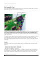
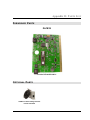
S HUTDOWN B UTTON
The PLC033 features a shutdown button that can be used to stop and start the ladder. The button can be
found on the edge of the card just below the service port.
Shutdown Button
Service Port
Holding the button down for several seconds sends a signal to the PLC033 to turn on the Remote Process
Stop Command register (Special Function Register 9921). The PLC033 will stop running the ladder
when one of two conditions occurs: it sees that the ladder has set the Remote Process Running register
(Special Function Register 9930) to false or 30 seconds has expired (in this case the PLC033 itself sets
register 9930 to false).
To restart the ladder, simply hold down the shutdown button again. This sends a signal to the PLC033 to
turn on both the Remote Process Start Command register (Special Function Register 9920) and the
Remote Process Running register (Special Function Register 9930). The PLC033 then starts running the
ladder again.
L OGIC
The PLC033’s ladder can be stopped and started using logic via the Remote Process Special Function
Registers:
Remote Process Start Command – register 9920
Remote Process Stop Command – register 9921
Remote Process Running – register 9930
For example, you could create controls on HyperTAC II that were mapped to registers 9920 and 9921.
This would allow you to turn a ladder off and on from a remote location over the radio telemetry link.
When the ladder sensed that the Remote Process Stop Command register was true, it could initiate
PLC033 Installation and Operation Manual
38
Appendix A: Testing and Troubleshooting
actions to put the station in a safe state for shutdown. The ladder would then be programmed to turn off
the Remote Process Running register, which lets the PLC033 know that it is safe to shutdown the ladder.
However, if the PLC033 doesn’t see that the Remote Process Running register has been turned off within
30 seconds of the Remote Process Stop Command coming on, it will turn off the register and stop the
process on its own.
You could also have a section in your ladder that would turn on the Remote Process Stop Command
register when a certain condition occurred. The ladder could be restarted by pressing the Shutdown
button for several seconds or via telemetry through a control mapped to the Remote Process Start
Command register.
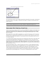
A DVANCED T ROUBLESHOOTING T OOLS
PMT’s Communication Tools (choose Comm Tools from the Tools menu) is a suite of advanced
troubleshooting tools for use by DFS Service personnel.
DFS-00507-011-01
39
Appendix A: Testing and Troubleshooting
Notes
PLC033 Installation and Operation Manual
40
Appendix B: APPLICATION NOTES
U SING R EMOTE DFS I/O
IN A
L ADDER
When creating a ladder to control a station or run a process, you may find it necessary to evaluate a
condition at another site in order to make a decision. For example, a tank level at station 1 determines
when a pump at station 35 goes on.
Getting the information into your ladder requires that you create a “logical” digital or analog input that
will hold the value of the I/O from the other station. These objects are by definition inputs to the ladder
from either a user or another I/O point.
Any I/O point that needs to be directly “writeable” from outside of the ladder must be assigned to the
writeable register ranges. As a result, the logical input discussed above must be assigned to an unused
register in either the 40001-49999 range (analog) or 1-9999 range (digital).
The logical input created in the ladder must then be mapped to an analog/digital module point in the DFS
radio map. An analog/digital output will then be configured in HyperTAC II as an auto control that is
controlled by the “real” I/O at the other station.
In our example, a logical analog input would be created in the ladder. This logical input would represent
the tank level at station 1. It would be assigned to a register in the 40000 range (for example, 41001).
The logical input would be mapped to an ACM module point in the DFS Radio Map.
41
Appendix B: Application Notes
On the HyperTAC II side, you would create an analog output with an address that matches that given to
the point in the radio map. For example, if the point was mapped to module A, point 1, it would have the
same address (plus the station number) in HyperTAC II.
You would then create an auto control for the logical point and use the point at the other station (in our
case the tank level at station 1, which has the address 1B3) as the source.
This allows the tank level value to be “pushed” into the AO point in HyperTAC II, which then pushes the
value into the PLC’s ladder when the logical input is examined.
(continued on next page)
PLC033 Installation and Operation Manual
42
Appendix B: Application Notes
Examine Analog object used to bring external data into the ladder
The examined input could be used in a ladder statement that evaluated the level at station 1 and turned on
the pump at station 35. For example, “if the tank level at station 1 is less than 25 feet, then turn on the
pump at station 35.”
Note: The Examine Analog object must be scaled to match the configuration in HyperTAC II.
I MPLEMENT PLC C ENTRAL F UNCTION
The PLC Central feature enables the PLC033 to poll remote DFS RTUs in addition to local modules and
local Modbus-compatible I/O. PLC Central can be a secondary function of the PLC033 or its primary
function. The PLC033’s mode is determined by the value of Special Function Register 9951 “Comm 2
DFS Central Mode.”
When register 9951 (“Comm 2 DFS Central Mode) is true, the PLC033 functions as a PLC Central and
polls all of the I/O configured under the DFS-PLC driver's "Remote" branch. When this register is false,
the PLC033 will not poll remote modules; it will only poll its local I/O and respond to queries received
over the DFS radio link.
As a secondary function (backup mode), the PLC033 can temporarily switch to PLC Central mode when
it determines that communications with the HyperTAC II central have been lost. This mode uses two
timers that are inserted in the PLC033’s ladder logic program. These timers instruct the PLC033 when it
should switch to PLC Central Mode (Comm 2 DFS Central Mode is “true”) and when it should return to
normal operation to check if communications with the HyperTAC II central have been restored (Comm 2
DFS Central Mode is “false”).
Special Function Register 49951, “Comm 2 Time Since Last Comm” is a timer (measured in seconds)
that monitors how long it has been since communications were received from the HyperTAC II central.
If the timer expires, the PLC033 starts operating in PLC Central mode. The second timer is a usercreated central mode timer that monitors how long the station has been in PLC Central mode (see line
125 in the ladder on the next page for an example). The second timer tells the PLC to return to normal
operation after the specified length of time, so it can check if communications have been restored.
DFS-00507-011-01
43
Appendix B: Application Notes
The ladder below presents code that can be used for most PLC Central "backup mode" operations. In this
example, the ladder switches modes based on loss of communication from a HyperTAC II central. If
register 49951, “Comm 2 Time Since Last Comm” reaches or exceeds 60 seconds, the PLC033’s
operation switches to central mode for sixty seconds (lines 115 and 120). When the central mode timer
reaches 60 seconds (lines 125 and 130), the PLC033 returns to normal operation mode (register 9951 is
reset to “false”) to determine if the central has come back online.
Figure B-1, PLC Central Backup Mode Ladder Code
For RTU systems that require a centralized site for logic, but aren’t large enough to warrant a HyperTAC
II central site, the PLC033 can be forced to permanently stay in PLC Central mode by setting and
keeping the Comm 2 DFS Central Mode register at a “true” value in the PLC033’s ladder logic program.
For example, the first line in the PLC033’s ladder logic program could be written to set the Comm 2 DFS
Central Mode register to “true” if power is detected.
(continued on next page)
PLC033 Installation and Operation Manual
44
Appendix B: Application Notes
The remote I/O that the PLC033 is to poll during PLC Central mode operation, must be configured under
the “Remote” branch in I/O Builder.
The process of adding DFS modules to the “Remote” branch is similar to the process used when adding
modules under the “Bus” branch with the addition of one step – the station number of the RTU where the
module(s) to be polled are located must also be specified.
1. Right-click Remote and select New.
2. In the New Remote Module dialog box, enter the station number assigned to the RTU.
3. In the Module Table, select the module’s type from the Module Type drop-down menu.
4. Similar to DFS local I/O, remote I/O must also be mapped. Enter valid, unused register numbers in
Start1 (and Start2 where applicable). To keep things organized, you may want to set aside a group
of registers in each Modbus register range that is only used for remote I/O.
DFS-00507-011-01
45
Appendix B: Application Notes
Notes
PLC033 Installation and Operation Manual
46
Appendix C: UPDATE PLC FIRMWARE
From time-to-time, we will make updates to the PLC’s firmware (the ROM-based software that controls
the device). These updates may add new features to the operation of the PLC or may fix bugs in the
previous release. When updates are available, they will be placed on our server and can be downloaded
and installed on the PLC via the Update command in the Process Management Toolkit.
To update the PLC’s firmware, you must be on a computer that has access to the PLC you want to
update. An Internet connection is optional but preferable. If you are connected to the Internet, you are
ensured of getting the latest firmware updates. Without an Internet connection, PMT will update the PLC
with any applicable updates that have been stored locally from a previous download. Files are stored
locally in a folder in the main PMT directory.
When you initiate the update process, PMT attempts to connect to our server. After successfully
connecting to our server, it compares the files on our server to those stored in the local PMT directory.
Any updates not found in the local folder are downloaded. If no Internet connection is found, only the
locally stored files will be used to update the PLC. After downloading the updates, the PMT connects to
the PLC, compares the PLC’s current firmware to the locally stored update files, and then makes the
necessary updates.
Firmware updates are typically 1-2Mb, although the file size could be smaller or larger depending on the
changes that have been made.
Firmware Update Procedure
Note: If you will be updating more than one RDP, a connection to the Internet is only required for the
first device. Once the update files have been downloaded to the PMT folder, you can update the
remaining RDP’s without being connected to the Internet; they can be updated using the locally-stored
files.
1. Start PMT and open the project file for the PLC you want to update.
2. Select Update PLC/RDP from the Network menu. The dialog box will show the download
progress (to the PMT folder).
3. When the updates have finished downloading, a second dialog box will show the file upload progress
(to the PLC). When the transfer is complete, click Done.
4. Reboot the PLC (cycle power) to finalize the updates.
47
Appendix C: Update PLC Firmware
Notes
PLC033 Installation and Operation Manual
48
Appendix D: PARTS LIST
F URNISHED P ARTS
PLC033
Part No. DFS-00507-008-01
O PTIONAL P ARTS
100Base-T Network Surge Arrestor
Part No. 002-0279
49
Appendix E: Parts List
Notes
PLC033 Installation and Operation Manual
50
Appendix E: RELEASE NOTES
March 7, 2008 Release
New Features
5. The PLC033 can now emulate up to two DFS RTUs. This allows developers to exceed the 15
module maximum for DFS RTUs. This is accomplished in the Radio Map by right-clicking the main
branch and selecting Add Remote Device. It is recommended that you choose the next station
number after the physical address of the station the PLC is installed in, and that you configure the
second station's RIM type as RIM004 in HyperTAC II. (e.g. If the PLC is in RTU #17 then add
remote device #18 in the Radio Map). The RTU will now respond as station 17 and 18 in
HyperTAC II.
6. The PLC033 and RDP180 now have a configurable Modbus slave device address for serial slave
function. This is configured in the settings panel of PMT as the Slave Device #. Prior to this change
the PLC/RDP would respond to any serial messaging. This feature allows the PLC/RDP to operate as
a serial slave device on 485 or radio networks where there is more than one slave device.
7. System variable addresses can now be obtained from logic builder. This is accomplished by rightclicking the desired object. Previously there was no easy way of determining what address the
builder had assigned un-addressed objects in the ladder.
8. The PMT is now the tool used to update the RNA110. This is accomplished by selecting Updated
RNA from the Network menu. This works similarly to the update RDP/PLC function. The PMT
obtains the update from our FTP server, but it prompts the user for the IP address of the target
RNA110 before installing the update.
Fixes
Ladders that had rungs of logic too large to fit on a single page would not print. The printing method
was overhauled to correct this and print ladders more efficiently.
9.
Analog registers were not being removed and/or recreated in the points list properly. The PMT now
performs a complete re-build of the points list each time a ladder check or install is performed. This
process is reflected with a “busy” progress bar at the bottom left of the PMT status bar.
10. Q Points were not being properly added to the logic file. This fix only applies to the PLC033.
11. A scaling error was corrected for analog points on the screen builder.
12. A math error was corrected with the flow totalizer object.
13. A condition that caused the PLC/RDP to intermittently crash when used as a Modbus TCP slave
device with HyperTAC II was corrected.
51
Appendix E: Release Notes
Notes
PLC033 Installation and Operation Manual
52
Appendix F: SUPPORT, SERVICE, AND WARRANTY
S UPPORT
AND
S ERVICE
Data Flow Systems, Inc. offers support services nationwide from its home office and through authorized
Value Added Resellers (VARs) and System Integrators. Contact your local Data Flow Systems, Inc.
representative for:
Sales and order support
Product technical training
Warranty support
Support service agreements
If you are unsure of whom to contact, call DFS’ Melbourne headquarters at 321-259-5009 and ask for the
Sales Department. Alternatively, send email to [email protected].
T ECHNICAL P RODUCT A SSISTANCE
Please review the information in Appendix A: Testing and Troubleshooting, before contacting Data Flow
Systems, Inc. If you need further assistance, contact your local Data Flow Systems representative. If you
are unsure of whom to contact, call DFS’ Melbourne headquarters at 321-259-5009 and ask for the
Service Department. Alternatively, send email to [email protected].
R ETURN A UTHORIZATION (RA) P ROCEDURE
Data Flow Systems’ function modules are designed to be robust and highly reliable. We back this
performance with a 3-year full warranty (see our warranty statement for details). In the event that a
function module fails, during or after the warranty period, it may be returned to Data Flow Systems to be
repaired or replaced.
All RA’s will be subject to standard shipping and handling charges. Minimum handling charge will be
assessed, in most cases, for work such as Radio Tuning, Backplanes, “No Problem Found,” and other
minor repairs. Handling charges will be waved on warranty equipment. Standard shipping and charges
will be based on UPS ground, please advise if other arrangements are needed (UPS Red, FedEx, Pickup,
Freight…). Standard cost of repairs and shipping charges can be obtained by contacting our RA
Department by phone or e-mail.
STEP 1: Replace the failed module with a spare module of the same type, if one is available.
STEP 2: Contact Data Flow Systems Inc. in one of the following ways to receive an RA#.
E-mail – An RA# can be obtained by e-mailing DFS at [email protected] and must include the
following information.
Customer/Utility Name and Ship to Address
Contact Name and Phone Number
53
Appendix F: Support, Service, and Warranty
Products to be returned and Serial Numbers
Detailed description of failure
PO#
Phone – RA# will be issued over the phone by calling DFS at 321-259-5009 during normal operating
hours. The following information will be needed.
Customer/Utility Name and Ship to Address
Contact Name and Phone Number
Products to be returned and Serial Numbers
Detailed description of failure
PO#
Note: The lack of “Detailed description of failure” could result in the return of equipment due to the
inability to properly determine the nature of the failure or testing resulting in “No Problem Found”
STEP 3: Place the function module(s) individually in an electrostatic discharge bag and then wrap with
foam or bubble wrap. Pack the wrapped module(s) in a sturdy box filled with popcorn-type or bubble
wrap packing material. Include a packing slip with the following information:
Module(s) model, serial number, probable cause of failure, and the RA number
Shipping address
Shipping instructions (shipping costs greater than UPS ground are charged to the customer)
STEP 4: Address the box to:
RA Department # {the RA number you received here}
Data Flow Systems, Inc.
605 N John Rodes Blvd.
Melbourne, FL 32934-9105
STEP 5: Ship the box to DFS using any typical shipping carrier (for example, UPS, FedEx, etc.). If
circumstances permit, have a DFS employee hand carry the package to the headquarters for you. NOTE:
DFS employees are not permitted to hand carry unpacked modules.
Modules are typically repaired and shipped back to the customer within a 2-week period starting at the
time the module reaches the RA Department. If additional information is required during the repair of the
module(s), the DFS service department will contact you.
To get information on the progress of any of your equipment in for repair, contact the DFS - RA
Department at [email protected] or 321-259-5009.
Replacement of equipment may be necessary in the event that the equipment and/or parts are
unrepairable. Warranty equipment will be replaced with out prior notification as warranty replacement.
The customer will be notified by phone, if equipment not under warranty cannot be repaired, with
information of available options.
DFS reserve the right to return any material received without an RA# or not conforming to the
requirements of this RA process.
PLC033 Installation and Operation Manual
54
Appendix F: Support, Service, and Warranty
W ARRANTY
Data Flow Systems, Inc. (DFS) offers a one (1) year on-site warranty covering defects in materials and
workmanship. All DFS “plug-in” function modules, Pump Control Units (PCU), Hyper Server Modules
(HSM), Network Interface Modules (NIM), Fiber Interface Modules (FIM), Network Switch Modules
(NSM), Network Fiber Modules (NFM), and Back Pack Radios (BPR) carry an extended two (2) year
return-to-factory warranty. This extended warranty does not cover misuse, vandalism, or Acts of God.
However, these items are warranted against damage due to lightning for the entire three-year period.
NOTICE
The intended purpose of the TCU is telemetry control. Using the TCU for purposes other than telemetry
control is not recommended and will void the warranty.
Q UESTIONS
OR
C OMMENTS
ON
T HIS M ANUAL
If you find a problem with any of the information in this manual or have suggestions on how it could be
improved, please contact us at the address below:
Data Flow Systems, Inc.
Documentation Department
605 N. John Rodes Blvd.
Melbourne, FL 32934
Alternatively, e-mail us at:
[email protected]
DFS-00507-011-01
55
Appendix F: Support, Service, and Warranty
Notes
PLC033 Installation and Operation Manual
56
INDEX
typical installation, 13
interface description, 6
IP address
determining for PLC033 using broadcast function,
36–37
battery voltage
controlled shutdown, 18, 39
low, 18, 39
board size, 5
cables
how to connect and disconnect, 11
communication protocols, 5
configuration bits, 5
connection refused error, 35
connector pins. See pins
connectors
how to connect and disconnect, 11
custom screens for monitor and control, 18
ladder logic, 17
remote DFS I/O, 43–45
shutdown, 41
due to low battery voltage, 39
using shutdown button, 40
using special function registers in logic, 40–41
LEDs, 5
logical I/O, 13
mapping I/O, 16
Modbus serial master, 3
Modbus serial master/slave device, 16
Modbus serial master/slave interface, 27–28
Modbus serial slave, 3
Modbus TCP protocol, 3
Modbus TCP slave, 3, 15
module communication
troubleshooting loss of, 32
module power
troubleshooting loss of, 34
multiple RTUs
emulating, 3, 14
description of PLC033, 3–4
DFS NIM RTU slave, 3, 15
electrostatic discharge
protecting against, 12
Ethernet. See network
factory default state
reset PLC033, 38
features of PLC033, 4
firmware
updating, 49
network interface, 5, 26–27
IP address, 27
network slave device, 3, 15
NIM RTU protocol, 3
NIM RTU slave, 3, 15
getting started, 21
I/O
remote, using in ladder logic, 43–45
I/O mapping, 16
installation, typical, 13
installign the PLC033
network interface
IP address, 27
installing the PLC033
cables and connectors, how to connect and
disconnect, 11
network interface, 26–27
PLC by-pass card, 26
protecting against electrostatic discharge, 12
radio, acceptable models, 23
RTU installation, 23
safety precautions, 11–12
serial interface, 27–28
operations overview, 13–18
custom screens for monitor and control, 18
I/O mapping, 16
logical I/O, 13
Modbus serial master/slave device, 16
network slave device, 15
PLC Central, 14
programmed with ladder logic, 17
programming interface, 17
RTU requirements, 13
set points (AKA Q points), 14
shutdown, controlled, 18, 39
support of multiple protocols, 16
57
Index
typical installation, 13
multiple, emulating, 3, 14
RTU installation of PLC033, 23
RTU requirements, 13
parts
furnished, 51
optional, 51
pins, descriptions, 9
PLC by-pass card, 26
PLC Central, 4, 14
implementing, 45–47
PLC033
description, 3–4
features, 4
installing
safety precautions, 11–12
IP address, determining, 36–37
pin desciptions, 9
reset to factory default state, 38
PMT. See Process Management Toolkit
principles of operation. See operations overview
Process Management Toolkit, 17
connection refused error, 35
processor type, 4
programming interface. See Process Management
Toolkit
protocols availabe for communication, 5
protocols supported, 16
safety
protecting against electrostatic discharge, 12
serial (Modbus) communication
troubleshooting loss of, 33–34
serial interface, 27–28
serial interfaces, 5
serial port, 3
service
obtaining, 55
set point registers, 6–7
set points, 14
shutdown button, 39, 40
shutdown, controlled, 18, 39
special function registers, 7–8
for stopping ladder logic, 40–41
specifications, 5
board size, 5
communication protocols, 5
configuration bits, 5
LEDs, 5
network interface, 5
serial interfaces, 5
supply current, 5
supply voltage, 5
supply current, 5
supply voltage, 5
support
obtaining, 55
Q points. See set points
quick start guide, 21
radio
acceptable models, 23
checking ROM version, 24–26
on ROM chip label, 24
using telemetry traffic tool, 25–26
using WinRTU Test software, 25
RAM, 4
register
special function, 7–8
registers
reserved set point, 6–7
release notes, 53–54
remote DFS I/O
using in ladder logic, 43–45
RIM locked in transmit mode, 35
ROM, 4
RTU
technical specifications. See specifications
troubleshooting
connection refused error, 35
determine IP address of PLC033, 36–37
module communication problems, 31–32
module power, loss of, 34
reset PLC033 to factory default state, 38
RIM locked in transmit mode, 35
serial (Modbus) communication problems, 33–34
updating PLC033 firmware, 49
warranty, 57
PLC033 Installation and Operation Manual
58
Data Flow Systems, Inc.
605 N. John Rodes Blvd.
Melbourne, FL 32934
321-259-5009
www.dataflowsys.com