1
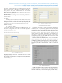
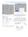
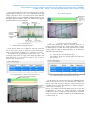
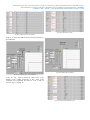
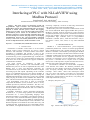
National Conference on Emerging Trends in Computer, Electrical & Electronics (ETCEE-2015)
International Journal of Advance Engineering and Research Development (IJAERD)
e-ISSN: 2348 - 4470 , print-ISSN:2348-6406,Impact Factor:3.134
Interfacing of PLC with NI-LabVIEW using
Modbus Protocol
Pooja Panchal1 , Prof. Alpesh Patel2
Instrumentation and control section, Institute of technology, Nirma Un iversity
Abstract - This paper focuses on interfacing of high end
Programmable Logic Controller with NI-LabVIEW using
Modbus RTU protocol. The aim behind doing this is to develop a
platform to enable real-time process control, data logging,
analysis etc. As on today PLC is the most widely used controller
in automation, process control etc. In industries, there is a
demand of supervisory control and data acquisition along with
the PLC based process control. The paper focuses on developing
communication between PLC and NI-LabVIEW (evaluation
version), so that a low cost S CADA platform can be de veloped.
In order to implement the idea, AB micro 830 PLC is used.
Keywords— NI-LabVIEW, PLC, Modbus RTU Protocol, SCADA
I. INT RODUCTION
Automation or automatic control refers to an area where
different control system co mponents are used to operate
mach ines with min imu m or reduced human intervention.
Automation is applicable and popular in most of the
manufacturing, production industries and is growing rapidly.
To automate any process, programmab le logic controllers are
widely used. As of date, lots of advancement has taken place
in the PLC. One of the impo rtant is the support of industrial
communicat ion standards.
The paper focuses on interfacing of high end
Programmab le Logic Controller with NI -Lab VIEW using
Modbus RTU protocol. In order to implement this idea, Allen
Brad ley PLC is used. AB M icro830 controllers are
economical brick style controllers with the number of dig ital
and analog inputs and outputs. Depending on the controller
type, it is accommodate fro m two to five plug-in modules. It
support the following commun ication protocols through the
embedded RS-232/ RS-485 serial port as well as any installed
serial port plug-in modules such as Modbus RTU Master and
Slave, CIP Serial Client/Server (RS-232 only) and ASCII [1].
The programming of the PLC is done in Connected
Co mponent Workbench (CCW) So ftware wh ich is freely
available provided by Rockwell auto mation. The IEC 6113
standard supports 6 languages. CCW supports Ladder logic,
Functional block diagra m and Structure text out of which we
are using Structure Text.
Lab VIEW (Laboratory Virtual Instrument Engineering
Workbench) is a system design platform and develop ment
environment for a visual programming language fro m
National Instruments. NI Lab VIEW system design software is
at the centre of the National Instruments platform provid ing
comprehensive tools that need to build any measurement or
control application in dramat ically less time, Lab VIEW is the
ideal development environment for innovation, dis covery, and
accelerated results. Co mb ine the power of Lab VIEW software
with modular, reconfigurable hardware to overcome the ever-
increasing comp lexity involved in delivering measurement
and control systems on time and under budget.
Modbus RTU protocol is used for the co mmun ication of A B
PLC and NI-Lab VIEW. Both support Modbus RTU protocol.
Modbus is typically used for Supervisory Control and Data
Acquisition (SCA DA)-style network co mmun ication between
devices. For examp le, a large server may be used to master a
programmab le logic controller (PLC) or programmable
automation controller (PA C), wh ile that PLC/PA C may in
turn master a sensor, valve, motor, or any other embedded
device.
II. MODBUS PROTOCOL
Modbus is a serial co mmunicat ions protocol originally
published by Modicon in 1979 for use with its programmable
logic controllers (PLCs).The co mmon language used by all
Modicon controllers is the Modbus protocol [2].The Modbus
protocol is used to exchange the data between the PLC and the
computers or HMI. This protocol built a message frame that
controllers will visualize and use, regardless of the type of
networks over which they need to commun icate. It describes
the process a controller uses to request access to another
device, how it will respond to requests fro m the other devices,
and how errors will be detected and reported [2].
The Modicon controllers use an RS–232C co mpatib le
serial interface that defines the different parameters like
connector pin outs, cabling, signal levels, trans mission baud
rates, and parity checking. The Controller transit using a
technique that is called master–slave technique in which
only one device (the master) can in itiate any transactions
(called ‗queries‘). The other devices (the slaves) respond by
supplying the requested data to the master, or by taking the
action requested in the query [2].
A. The Query–Response Cycle
Fig.1 Master–Slave Query–Response Cycle
National Conference on Emerging Trends in Computer, Electrical & Electronics (ETCEE-2015)
International Journal of Advance Engineering and Research Development (IJAERD)
e-ISSN: 2348 - 4470 , print-ISSN:2348-6406,Impact Factor:3.134
The Query: The function code in the query informs the
addressed slave device what kind of action to be performed.
For examp le, if the function code 03 will query the slave to
read holding registers and respond with their contents. The
data field must contain the in formation telling the slave which
register to start at and how many registers to read. The error
check field provides a method for the slave to validate the
integrity of the message contents [2].
The Response: If the slave responds normally, the function
code in the response is an echo of the function code in the
query. The data bytes contain the data that is collected by the
slave, such as register values. If any error occurs, the function
code is modified and also indicates that the response is an
error response, and the data bytes contain a code that
describes the error. The error check field allows the master to
confirm that the message contents are valid [2].
B. The Serial Transmission Modes
Modbus networks using either of two transmission modes:
ASCII or RTU. Users select the desired mode, along with the
serial port co mmunication parameters (baud rate, parity mode,
etc.), during configuration of each controller. The mode and
serial parameters must be the same fo r all devices on a
Modbus network [2].
1) ASCII : When controllers are setup to communicate on a
Modbus network using ASCII (A merican Standard Code
for Info rmation Interchange) mode, each 8–bit byte in a
message is sent as two ASCII characters. The main
advantage of this mode is that it allows time intervals of
up to one second to occur between characters without
causing an error [2].
Character density allows better data throughput than ASCII
for the same baud rate. Each message must be transmitted in a
continuous stream [2].
TABLE II
The format for each byte in RTU mode
C. Function code used in MODBUS Protocol
TABLE III
Function Code of Modbus
TABLE I
The format for each byte in ASCII mode
D. MODBUS Data model
TABLE IV
Modbus data model
2) RTU: When controllers are setup to communicate on a
Modbus network using RTU (Remote Terminal Un it) mode,
each 8–bit byte in a message contains two 4–bit hexadecimal
characters. The main advantage of this mode is that it‘s
greater
III. M ODBUS IN PLC
M icro830
controllers
support
the
follo wing
communicat ion protocols through the embedded RS-232/RS-
National Conference on Emerging Trends in Computer, Electrical & Electronics (ETCEE-2015)
International Journal of Advance Engineering and Research Development (IJAERD)
e-ISSN: 2348 - 4470 , print-ISSN:2348-6406,Impact Factor:3.134
485 serial port as well as any installed serial port p lug -in
modules:
A. Modbus RTU Master and Slave
Modbus is a half-duplex, master-slave commun ications
protocol. The Modbus network master reads and writes bits
and registers. Modbus protocol allows a single master to
communicate with a maximu m of 247 slave devices.
Micro800 controllers support Modbus RTU Master and
Modbus RTU Slave protocol [1].
1) Configure Modbus RTU;
1. Open the Connected Components Workbench project. On
the device configuration tree, click on Controller properties
and then Click Serial Port as shown in Fig. 2.
3. Select the Baud rate by default 19200, parity is none,
Modbus role (master, slave).
4. Click Advanced Settings to set advanced parameters as
shown in Fig. 3.
B. CIP Symbolic Client/Server
This protocol allows HMIs to easily connect to the
Micro830/Micro 850 controller [1].
1) Configure CIP Serial Driver:
1. Open the Connected Components Workbench project. On
the device configuration tree, click on Controller properties
and then Click Serial Port as shown in Fig. 4.
Fig.4 Serial Port Configuration of CIP Serial Driver
Fig.2 Serial Port Configuration
2. Select CIP Serial fro m the Driver field.
2. Select Modbus RTU on the Driver field
Fig.3 Serial Port Configuration on the Driver Field
Fig.5 CIP Serial Driver
National Conference on Emerging Trends in Computer, Electrical & Electronics (ETCEE-2015)
International Journal of Advance Engineering and Research Development (IJAERD)
e-ISSN: 2348 - 4470 , print-ISSN:2348-6406,Impact Factor:3.134
3. Specify a baud rate. Select a commun ication rate that the
devices in the system will support. Configure all devices in
the system for the same commun ication rate. The Default
baud rate is set at 38400 bps.
4. In most cases, parity and station address should be left at
default settings.
5. Click Advanced Settings and set advanced parameters as
shown in Fig. 5.
C. ASCII
ASCII provides connection to other ASCII devices, such
as bar code readers, weigh scales, serial printers, and other
intelligent devices. You can use ASCII by configuring the
embedded or any plug-in serial RS232/RS485 port for the
ASCII driver [1].
1) Configure ASCII:
1. Open the Connected Components Workbench project. On
the device configuration tree, click on Controlle r properties
and then Click Serial Port.
2. Select ASCII on the Driver field
Fig.7 Advanced configuration setting
IV. M ODBUS IN NI-LABVIEW
Lab VIEW (Laboratory Virtual Instrument Engineering
Workbench) is a system-design platform and development
environment for a visual programming language fro m
National Instruments.Lab VIEW was extensively used in the
laboratory sessions, which better prepared students for the
course projects [3]. Many researchers and engineers use
Lab VIEW fo r testing and rapid prototyping in the product
development process [4]. Lab VIEW has been used to teach
dynamic systems and controls [5].
We have used two function blocks fro m NI-LA BVIEW
namely MB Serial INT and MB Serial Master Query for
establishing communicat ion between PLC and NI-LA BVIEW.
In M B Serial INT block, specify the visa resource name,
baud rate, parity, flow control, timeout mode as shown in
Fig. 8.
Fig.6 Configuration of ASCII
3. Specify baud rate and parity, by default baud rate is 19200
and parity is none.
4. Click Advanced Settings to configure advanced parameters
as shown in Fig. 7.
Fig.8 MB Serial Initialization
In MB Serial Master Query block, the fo llo wing parameters
are shown in Fig. 9. A GUI designed in Lab VIEW makes the
real-t ime monitoring as well as data logging possible. In Fig.
National Conference on Emerging Trends in Computer, Electrical & Electronics (ETCEE-2015)
International Journal of Advance Engineering and Research Development (IJAERD)
e-ISSN: 2348 - 4470 , print-ISSN:2348-6406,Impact Factor:3.134
10 the NI-Lab VIEW based SCADA is developed for
MODBUS REA D and WRITE.
Fig.11 Developed front panel diagram
Fig.9 MB Serial Master Query
V. INTERFACING OF PLC WITH NI -LABVIEW
MODBUS defined as the communicat ion protocol for
establishing commun ication between PLC and Lab VIEW. It
allo ws the exchange of data between PLCs and co mputers. So
for the interfacing the programming cable is required.
A. Embedded Serial Port Wiring
The embedded serial port is a non-isolated RS232/RS485
serial port wh ich is targeted to be used for short distances
(<3m) to devices such as HMIs. For the interfacing 1761CBL-PM02 cable is typically used to connect the embedded
serial port to Panel View Co mponent of Scada using
RS232.One end of DB 8 PIN is connected in PLC(as slave)
and another end is connected in computer(Master) or HMI[1].
Fig.10 Developed block diagram for MODBUS Read and Write
Fig.12 Embedded Serial Port Wiring
VI. TEST ING RESULT
A. Digital On-Off
National Conference on Emerging Trends in Computer, Electrical & Electronics (ETCEE-2015)
International Journal of Advance Engineering and Research Development (IJAERD)
e-ISSN: 2348 - 4470 , print-ISSN:2348-6406,Impact Factor:3.134
In the Allen Bradley PLC there are 20 dig ital inputs and 28
digital outputs as shown in Fig. 13. For the digital inputs and
outputs assigned in PLC we separate them with different
addresses which is given in MODBUS Addressing Frame. For
the digital Input the address starts with 10000 and for dig ital
output the address starts with 00001.
Fig.15 Result of digital on.
Fig.16 Result of digital off.
Fig.13 Allen Bradley PLC
1)
Discrete Input and Output(Coils)
In the discrete input it is o f single bit with only read type
and in the coil it is same as Input but both read/write type
which is shown in Fig. 14.Here is one examp les for on-off.
The Ladder logic programming is done in the PLC and
according to that when we apply some input the output will
glow and when we remove it the output is zero or off as
shown in Fig. 15 and Fig. 16.
B.
Continuous Data Read and Write
In the Allen Bradley PLC there are 4 analog input and 2
analog output as shown in Fig. 13.The analog input is called
as Input register of 16 Bit- Word and only Read type and the
analog output is called as Hold ing Reg ister of 16 Bit-Word
and both read and write type.
1) Input Register and Holding Register
The Address assign for Analog Input and output are
shown in Fig. 17.
.
Fig.14 Modbus mapping of discrete input and output in PLC
Fig.17 Modbus mapping of analog input and output in PLC
For the data to be read and write the NI-LA BVIEW based
Scada is developed in such a way that when the condition is
false it starts read the data in Reg ister output and when the
condition is true its starts write the data in Register output as
shown in Fig. 18 and Fig. 19.
Here is one examp le for the data Read and write. In this the
programming is done in CCW(Co mponent Connected
workbench) software in Structure text and Scada is developed
using two blocks of Modbus available in NI-LABVIEW that
is shown in Fig. 10.
National Conference on Emerging Trends in Computer, Electrical & Electronics (ETCEE-2015)
International Journal of Advance Engineering and Research Development (IJAERD)
e-ISSN: 2348 - 4470 , print-ISSN:2348-6406,Impact Factor:3.134
Fig.20 PLC data status in CCW
Fig.18 PLC data status in CCW Software
In figure 19 shows the different data‘s are Read fro m PLC to
NI-LABVIEW
Fig.21 PLC data Write in LabVIEW
Fig.19 Data read from PLC to NI-LABVIEW
In fig. 20 the data of setpoint in yellow circle is zero
initially in the variable monitoring of PLC. After giv ing
command fro m LABVIEW the Data are write in PLC as
shown in Fig. 21 and Fig. 22.
Fig.21 Write data from LabVIEW to PLC
National Conference on Emerging Trends in Computer, Electrical & Electronics (ETCEE-2015)
International Journal of Advance Engineering and Research Development (IJAERD)
e-ISSN: 2348 - 4470 , print-ISSN:2348-6406,Impact Factor:3.134
VII.
CONCLUSIONS
Th is paper discusses the effectiveness of using
Lab VIEW to learn the Modbus Rs -232 co mmunicat ion
protocol. We have successfully imp lemented the different
modes of Modbus and also develop a low cost Scada in NILA BVIEW platform. After the implementation we gather the
data from PLC and LA BVIEW using MODBUS RTU
Co mmunicat ion Protocol. Using the low cost SCA DA we
practically visualize d ifferent graphs as shown in different
figures.
A CKNOWLEDGMENT
The success of any project depends largely on the
encouragement and guidelines of many others . We would like
to convey our deepest gratitude to Dr.Jayesh Barve for their
invaluable guidance, constant encouragement and continuous
support in all our endeavours and showing faith in us. We
would also like to thank Rockwell Automation p rivate limited
for their support.
REFERENCES
[1]
Micro830 and Micro850 Programmable Controllers user manual.
Available: http://www.Rockwellautomation.com
[2] Modicon Modbus Protocol Reference Guide PI– MBUS–300 Rev.
J, June 1996. Available:
https://www.we b.eecs.umich.edu/~modbus/documents/PI_MBUS_300.pdf
[3] Wei Zhan, Jay R. Porter, and Joseph A. Morgan,‖ Experiential Learning
[4]
[5]
[6]
[7]
Of Digital Communication Using LabVIEW‖, IEEE Transactions on
Education, vol. 57, no. 1, February 2014.
P. Pillay and Z. Xu, ―LabVIEW implementation of speed detection for
mains-fed motors using motor current signature analysis,‖ IEEE Power
Eng. Rev., vol. 18, no. 6, pp. 47–48, Jun. 1998.
C. Salzmann, D. Gillet, and P. Huguenin, ―Introduction to real-time
control using LabVIEW with an application to distance learning,‖ Int.
J. Eng. Educ., vol. 16, pp. 255–272, 2000.
Introduction to Modbus. Available: http://www.ni.com/whitepaper/7675/en/
Modbus
Library
for
LabVIEW.
Available:
http://www.ni.com/example/29756/en/