1
»
D00871101A
X-48
48 Track Digital Audio Workstation
OWNER'S MANUAL
IMPORTANT SAFETY PRECAUTIONS
CAUTION: TO REDUCE THE RISK OF ELECTRIC SHOCK, DO NOT REMOVE
COVER (OR BACK). NO USER-SERVICEABLE PARTS INSIDE. REFER SERVICING
TO QUALIFIED SERVICE PERSONNEL.
The lightning flash with arrowhead symbol, within equilateral triangle, is intended
to alert the user to the presence of uninsulated “dangerous voltage” within the
product’s enclosure that may be of sufficient magnitude to constitute a risk of
electric shock to persons.
The exclamation point within an equilateral triangle is intended to alert the user to
the presence of important operating and maintenance (servicing) instructions in
the literature accompanying the appliance.
This appliance has a se rial numbe r
located on the rear panel. Please record
the model number and serial number
and retain them for your records.
Model number
Serial number
WARNING: TO PREVENT FIRE OR
SHOCK HAZARD, DO NOT EXPOSE THIS
APPLIANCE TO RAIN OR MOISTURE.
For U.S.A.
For the customers in Europe
TO THE USER
WARNING
This is a Class A product. In a domestic
environment, this product may cause radio
interference in which case the user may be required
to take adequate measures.
This equipment has been tested and found to
comply with the limits for a Class A digital device,
pursuant to Part 15 of the FCC Rules. These limits
are designed to provide reasonable protection
against harmful interference when the equipment
is operated in a commercial environment. This
equipment generates, uses, and can radiate radio
frequency energy and, if not installed and used in
accordance with the instruction manual, may cause
harmful interference to radio communications.
Operation of this equipment in a residential area is
likely to cause harmful interference in which case the
user will be required to correct the interference at his
own expense.
Pour les utilisateurs en Europe
AVERTISSEMENT
I l s'a g i t d 'u n p r o d u i t d e C l a s s e A . D a n s u n
environnement domestique, cet appareil peut
provoquer des interférences radio, dans ce cas
l'utilisateur peut être amené à prendre des mesures
appropriées.
Für Kunden in Europa
CAUTION
Changes or modifications to this equipment not
exp re s sly a pp rove d by TE AC COR POR ATION
for compliance could void the user's authority to
operate this equipment.
Warnung
Dies ist eine Einrichtung, welche die Funk-Entstörung
nach Klasse A besitzt. Diese Einrichtung kann im
Wohnbereich Funkstörungen versursachen ; in
diesem Fall kann vom Betrieber verlang werden,
angemessene Maßnahmen durchzuführen und dafür
aufzukommen.
CE Marking Information
a) Applicable electromagnetic environment: E4
b) Peak inrush current: 20 A
IMPORTANT SAFETY INSTRUCTIONS
1 Read these instructions.
• Do not expose this apparatus to drips or splashes.
2 Keep these instructions.
• Do not place any objects filled with liquids, such as
vases, on the apparatus.
3 Heed all warnings.
• Do not install this apparatus in a confined space such
as a book case or similar unit.
4 Follow all instructions.
• The apparatus should be located close enough to the
AC outlet so that you can easily grasp the power cord
plug at any time.
5 Do not use this apparatus near water.
6 Clean only with dry cloth.
• An apparatus with Class I construction shall be
connected to an AC outlet with a protective grounding
connection.
7 Do not block any ventilation openings. Install in
accordance with the manufacturer's instructions.
• Batteries (battery pack or batteries installed) should
not be exposed to excessive heat such as sunshine,
fire or the like.
8 D o not install nea r any heat source s such a s
radiators, heat registers, stoves, or other apparatus
(including amplifiers) that produce heat.
• Excessive sound pressure from earphones and headphones can cause hearing loss.
9 Do not defeat the safety purpose of the polarized
or grounding-type plug. A polarized plug has two
blades with one wider than the other. A grounding
type plug has two blades and a third grounding
p rong. T he wide blade or the third prong a re
provided for your safety. If the provided plug does
not fit into your outlet, consult an electrician for
replacement of the obsolete outlet.
• The apparatus draws nominal non-operating power
from the AC outlet with its STANDBY/ ON in the
Standby position.
10 Protect the power cord from being walked on
or pinched par ticularly at plugs, convenience
receptacles, and the point where they exit from the
apparatus.
11 Only use attachments/accessories specified by the
manufacturer.
12 Use only with the cart, stand, tripod, bracket, or
table specified by the manufacturer, or sold with the
apparatus. When a cart is used, use caution when
moving the cart/apparatus combination to avoid
injury from tip-over.
13 Unplug this apparatus during lightning storms or
when unused for long periods of time.
14 Refer all servicing to qualified service personnel.
Servicing is required when the apparatus has been
damaged in any way, such as power-supply cord or
plug is damaged, liquid has been spilled or objects
have fallen into the apparatus, the apparatus has
been exposed to rain or moisture, does not operate
normally, or has been dropped.
Safety Information
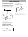
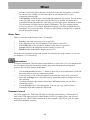
Rack-mounting the Unit
This product has been designed and manufactured
according to FDA regulations "title 21, CFR, chapter
1, subchapter J, based on the Radiation Control for
Health and Safety Act of 1968", and is classified as
a class 1 laser product. There is no hazardous invisible laser radiation during operation because invisible laser radiation emitted inside of this product is
completely confined in the protective housings.
The label required in this regulation is shown at 1.
Use the supplied rack-mounting kit to mount the unit in a
standard 19-inch rack, as shown below.
Remove the feet of the unit before mounting.
CERTIFICATION
COMPLIES WITH 21 CFR
1040, 10 AND 1040, 11 EXCEPT FOR DEVIATIONS PURSUANT
TO LASER NOTICE NO. 50, DATED JULY 26, 2001.
MANUFACTURED
TEAC CORPORATION
3-7-3 NAKA-CHO, MUSASHINO-SHI, TOKYO, JAPAN
NOTE
• Leave 1U of space above the unit for ventilation.
• Allow at least 10 cm (4 in) at the rear of the unit for
ventilation.
CAUTION
•DO NOT REMOVE THE PROTECTIVE HOUSING
USING A SCREWDRIVER.
•USE OF CONTROLS OR ADJUSTMENTS OR
PERFORMANCE OF PROCEDURES OTHER THAN
THOSE SPECIFIED HEREIN MAY RESULT IN
HAZARDOUS RADIATION EXPOSURE.
•IF THIS PRODUCT DEVELOPS TROUBLE,
CONTACT YOUR NEAREST QUALIFIED SERVICE
PERSONNEL, AND DO NOT USE THE PRODUCT
IN ITS DAMAGED STATE.
Optical pickup:
Type:
SF-DS10L
Manufacturer: SANYO
Laser output: 108 mW max (CD), 66 mW max (DVD)
Wavelength: 782 nm (CD), 658nm (DVD
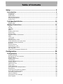
Table of Contents
Setup ................................................................................................. 9
Introduction ...................................................................................... 9
Introduction.......................................................................................................... 9
Unpacking ............................................................................................................ 9
Read & Surf .......................................................................................................... 9
Manual Conventions ............................................................................................... 9
Required Equipment............................................................................................. 10
Guided Tour........................................................................................................ 11
I/O Card Installation....................................................................... 13
Analog Card........................................................................................................ 13
Digital Card ........................................................................................................ 13
Making Connections ........................................................................ 14
TDIF .................................................................................................................. 14
S/PDIF ............................................................................................................... 14
AES/EBU ............................................................................................................ 14
ADAT ................................................................................................................. 15
Digital Audio Clock............................................................................................... 15
Word Clock ......................................................................................................... 15
Analog Audio ...................................................................................................... 15
Synchronization and Control.................................................................................. 16
MIDI.................................................................................................................. 16
Time Code .......................................................................................................... 16
Footswitch .......................................................................................................... 16
Remote (Sony 9-Pin)............................................................................................ 16
Video Reference (Tri Level Sync) ........................................................................... 17
Keyboard, Mouse & Monitor................................................................................... 17
Network ............................................................................................................. 17
External Drives ................................................................................................... 18
Powering On / Off ................................................................................................ 18
External Applications............................................................................................ 18
VST Plug-ins ....................................................................................................... 19
Using the X-48 System Restore CD ........................................................................ 19
Configuration................................................................................... 20
Configuration .................................................................................. 20
Display Settings .................................................................................................. 20
Navigating the LCD Interface................................................................................. 20
Sample Rates...................................................................................................... 21
Digital Audio Clock............................................................................................... 22
I/O Settings........................................................................................................ 23
Analog I/O Operating Level ................................................................................... 24
Control Mode ...................................................................................................... 24
MIDI Device ID ................................................................................................... 24
Sony 9-Pin.......................................................................................................... 25
Video Reference .................................................................................................. 25
Pull Up/Pull Down Sample Rates ............................................................................ 26
Networking ......................................................................................................... 26
Checking Free Hard Drive Space ............................................................................ 28
Drive Benchmarking Utility.................................................................................... 28
Formatting a New Drive........................................................................................ 28
Factory Defaults .................................................................................................. 29
Store/Recall User Settings .................................................................................... 29
Mixer Bypass ...................................................................................................... 30
5
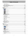
Table of Contents
Make a Default Project ......................................................................................... 30
Install VST Plug-Ins ............................................................................................. 30
Recorder .......................................................................................... 31
Working With Projects .................................................................... 31
Creating a New Project ......................................................................................... 31
Opening a Project ................................................................................................ 32
Saving a Project .................................................................................................. 32
Auto-Saving Projects............................................................................................ 33
Importing a Project.............................................................................................. 33
Exporting a Project .............................................................................................. 34
Copying a Project ................................................................................................ 34
Backing Up a Project to CD/DVD ............................................................................ 35
Deleting a Project ................................................................................................ 35
Load Last Project ................................................................................................. 35
Transport Operations ...................................................................... 36
Local ................................................................................................................. 36
One-Button Record .............................................................................................. 36
TC Chase............................................................................................................ 37
Rehearse............................................................................................................ 37
Pre/Post Roll ....................................................................................................... 37
Varispeed ........................................................................................................... 38
Recording and Playing Back ............................................................ 38
Input Monitoring.................................................................................................. 38
Record Enable ..................................................................................................... 39
Punch Crossfade Time .......................................................................................... 39
Undo/Redo ......................................................................................................... 40
Metering ............................................................................................................ 40
Using Markers ..................................................................................................... 41
Loop Playback ..................................................................................................... 41
Loop Mode.......................................................................................................... 41
Auto Punch ......................................................................................................... 42
Loop Recording ................................................................................................... 43
Using the VGA Recorder Interface ................................................... 43
Meters ............................................................................................................... 43
Naming Tracks .................................................................................................... 43
Scrolling............................................................................................................. 43
Timebar Format .................................................................................................. 43
Clip Properties..................................................................................................... 44
Navigating the Timeline ........................................................................................ 44
Status Displays ................................................................................................... 44
Input Routing...................................................................................................... 44
Synchronization .............................................................................. 45
Requirements ..................................................................................................... 45
Sample Rate ....................................................................................................... 46
Clock Source....................................................................................................... 47
BNC Clock In/BNC Clock Out ................................................................................. 47
BNC Word Clock Output Polarity ............................................................................ 48
Video Clock Frame-Edge Resolve ........................................................................... 48
Frame Rate......................................................................................................... 48
Control Mode ...................................................................................................... 49
Chase Freewheel ................................................................................................. 50
Chase Relock ...................................................................................................... 50
Chase Relock Threshold........................................................................................ 51
6
Table of Contents
Timecode Offset .................................................................................................. 51
Chase Lock Deviation ........................................................................................... 51
Timecode Output Muting....................................................................................... 52
Advanced Recorder Operations ....................................................... 52
Audio File Naming................................................................................................ 52
Track Key Punch.................................................................................................. 53
Editing ............................................................................................. 54
Edit Tools ........................................................................................ 54
I-Beam Tool............................................................................................. 54
Object Tool .............................................................................................. 54
Smart Tool .............................................................................................. 55
Magnify Tool ............................................................................................ 55
Selecting & Editing .......................................................................... 55
Selecting Clips .................................................................................................... 55
Selecting Time .................................................................................................... 55
In and Out Points ................................................................................................ 55
Clip Properties..................................................................................................... 56
Snap to Grid ....................................................................................................... 56
Cut, Copy, Delete, Paste....................................................................................... 56
Repeat Paste....................................................................................................... 57
Crop .................................................................................................................. 57
Insert Time......................................................................................................... 57
Delete Time ........................................................................................................ 57
Split .................................................................................................................. 57
Play From Selection ............................................................................................. 57
History List ......................................................................................................... 57
Audio Processing............................................................................. 58
Pitch/Time Stretch ............................................................................................... 58
Consolidate......................................................................................................... 58
Mixer................................................................................................ 59
Mixer Interface ............................................................................... 59
Mixer Introduction ............................................................................................... 59
Mixer Bypass ...................................................................................................... 59
DSP View .............................................................................................. 59
Mixer Tabs.......................................................................................................... 60
Automation.............................................................................................. 60
External Control .................................................................................................. 60
Third-Party Plug Ins ............................................................................................. 61
CPU Meter .......................................................................................................... 61
Routing .............................................................................................................. 61
Mixer Applications ........................................................................... 61
Submixing .......................................................................................................... 61
Monitoring While Recording ................................................................................... 62
Final Mix ............................................................................................................ 62
7
Table of Contents
Specifications .................................................................................. 63
Audio I/O ........................................................................................ 63
Miscellaneous I/O connections ....................................................... 63
Physical characteristics ................................................................... 63
8
Setup
Setup
Introduction
Introduction
Thank you for purchasing the TASCAM X-48 Digital Audio Workstation. You will find it a
powerful addition to your audio recording workflow. With normal use and attention to the
available documentation, the X-48 will provide many years of service. Enjoy!
Unpacking
The X-48 has been packed to ensure its safety during shipment. Inspect the unit for damage
immediately upon unpacking and contact the shipper or retailer if damage is discovered or
items appear to be missing. Please keep all boxes and packing material in case your X-48
needs to be shipped in the future. Inside the shipping carton, you will find the following:
•
•
•
•
•
•
•
This Owner’s Manual
Quick Reference Guide
X-48 Unit
Power Cable specific to the country you purchased it in
System Restore CD
Documentation CD
Two white plastic spacers & screws for installation of digital cards(IF-AE24/IFAD24)
Read & Surf
We know you’re eager to start recording right away. While you may get going by simply
reading the Quick Start Guide, it is strongly recommended that you read this Owner’s
Manual and check http://www.tascam.com for any software updates. Doing these two
simple things will go a long way towards making your experience with the X-48 an
enjoyable one.
Manual Conventions
The following typefaces will be used in this Owner’s Manual as indicated:
Bold is used for front panel controls
Italic is used for VGA controls
A Courier font is used for LCD display items
The following icons will be used in this Owner’s Manual as indicated:
This icon is for instructions that must be followed to avoid data loss or poor
performance.
This icon indicates a hint or tip on using the X-48.
9
Setup
This icon indicates instructions related to using the keyboard, mouse & monitor
interface.
This icon indicates instructions related to using the front panel of the X-48.
Required Equipment
While the X-48 is a comprehensive piece of professional audio gear, there are other things
you may need to take full advantage of its capabilities:
•
•
•
•
•
A console with a minimum of 8 outputs (at least 24 is recommended) and enough
inputs to handle your expected track count.
An optional IF-AN24X analog I/O card if connecting the X-48 to an analog console.
The IF-AN24X provides the X-48 with 24 analog inputs and 24 analog outputs.
An optional digital I/O card (IF-AD24(X) or IF-AE24(X)) if connecting your X-48
to a digital console so equipped. These cards provide the X-48 with 24 digital inputs
and 24 digital outputs per card.
Analog or digital cables appropriate to your console and choice of I/O format.
In order to use the X-48’s editing, DSP and mixing capabilities, you will need a
VGA monitor (1024 x 768 minimum resolution), a two-button PC mouse (PS/2 or
USB) and a PC keyboard (PS/2 or USB).
10
Setup
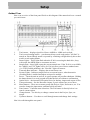
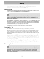
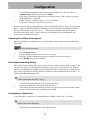
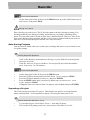
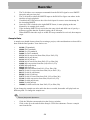
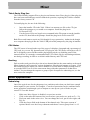
Guided Tour
Here is an overview of the front panel. Refer to this diagram if the manual refers to a control
you can't locate:
1.
2.
3.
4.
5.
6.
7.
8.
9.
10.
11.
12.
13.
Track meter – displays signal level from -60dBfs to -1dBfs and overload.
Track record arming button – puts that track into record ready unless "All Safe" is
turned on. Record Ready status is reported by a flashing red light directly above that
track's record arming button.
Status Lights – These lights flash when the X-48 is accessing the hard drive, busy
with a task, has MIDI input or encounters an error.
Sample Rate – these lights report the current sample rate. If the X-48 is set to 96kHz,
the "48kHz" and "2X" lights will be lit. If it isn't set to one of these standard rates
(i.e. 47952 Hz/48k pulldown), the "Non Std." light will turn on.
Timecode Rate indicator – Displays the current frame rate.
System Lights – Indicates sample lock to an external source, when destructive
recording mode is enabled and when varispeed is enabled.
Power – Turns the unit on and off. A system prompt will confirm shutdown. Holding
the button down for several seconds will shut the unit off without a confirmation.
Optical drive – the internal DVD optical drive for backup, import and export of files.
Transport buttons – See the Recorder chapter if you're unsure how to use these.
Menu buttons – These access menu groups like Project, Sync, Preferences, etc. You
can also change the input status, unmount a disk and more.
Enter button – Confirms menu selections. The Exit button is directly below it to
cancel a menu option.
Change button – Use this key to change a menu item in the Project, Sync, etc.
menus.
Up/Down buttons – Use these to scroll through menus and change their settings.
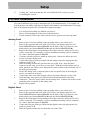
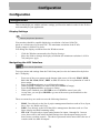
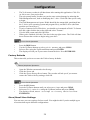
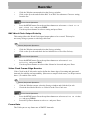
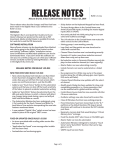
Now let's walk through the rear panel:
11
Setup
1.
2.
3.
4.
5.
6.
7.
8.
9.
10.
11.
12.
13.
14.
15.
16.
TDIF Inputs and Outputs – Each of these jacks transmits 8 channels of TDIF-format
digital audio input and output at up to 96kHz/24-bit. NOTE: to get all 8 channels of
audio input and output at 96kHz, the equipment connected to the X-48 must have the
latest TDIF capabilities, such as TASCAM’s DM-3200 and DM-4800 digital mixers.
Option card slot 1 – This card slots adds an additional I/O format for channels 1-24.
It's compatible with an interface card such as the IF-AN24X analog card, IF-AD24
ADAT optical card or IF-AE24 AES/EBU card (sold seperately).
Option card slot 2 – Adds an additional I/O format for channels 25-48. Cards 1 and 2
do not need to be the same, you can mix and match Analog and AES for example.
MIDI Input and Output – Used to generate and receive MIDI Timecode. Also used
to receive MIDI Machine Control commands.
Timecode Input and Output – Generates and receives SMPTE LTC timecode
through balanced 1/4" jacks.
Footswitch jack – Compatible with a momentary footswitch like the TASCAM RC30P for punch in/punch out. NOTE: To operate correctly, as footswitch must be
connected before the X-48 is powered on.
Remote – Compatible with RS-422 / Sony 9-pin edit controllers for machine control
Video clock in/thru – Attach blackburst video reference to this BNC jack. There's
also an auto-terminating thru jack.
Mouse/Keyboard – PS/2-compatible mouse and keyboard inputs. You can also use a
USB mouse and keyboard if preferred.
Word Sync In/Out/Thru – Compatible with BNC word clock generators.
VGA output – Your monitor should be capable displaying a resolution of at least
1024x768 pixels at a refresh rate of at least 60 Hz. The maximum resolution of the
X-48's display output is 2048x1536 pixels.
Option – This jack doesn't do anything and never will. Just pretend it doesn't exist.
USB – Four USB 2.0 jacks for connecting a keyboard, mouse, flash drive or hard
drive.
Ethernet – There are two ethernet jacks. One is 10/100/1000 (Gigabit compatible)
and the other is 10/100. The Gigabit port is fully configurable while the 10/100 port
is set to DCHP. See the section on Networking for more information.
S/PDIF – Stereo coaxial digital input and output.
Firewire – A pair of FireWire connectors for connecting external hard drives
12
Setup
17.
Cooling fan – make sure that this fan is not blocked off in a rack to prevent
overheating the system.
I/O Card Installation
I/O cards of different types may be installed in the X-48 simultaneously. For example, an
X-48 may have one analog card and one digital card installed, with independent I/O routing.
Each X-48 option card provides 24 channels of input and output.
•
•
•
You will need a medium size Philips screwdriver.
Power off and unplug the X-48 to avoid shock hazard.
If rack mounted, remove the X-48 from the rack to gain access to the top panel.
Analog Card
1.
2.
3.
4.
5.
6.
7.
8.
9.
10.
Remove the six screws holding on the top panel (there is one on the rear).
Remove the top panel and set it aside. You will see two black connectors, one
labeled SLOT1 and one labeled SLOT2. On the back of the X-48, there are two
blank panels, one labeled SLOT1 (1-24) and one labeled SLOT2 (25-48).
Remove the blank panel corresponding to the black connector where the I/O card
will be connected. For example, if you are installing an analog card for channels 124, remove the blank panel for SLOT1.
Continue with this section to install an analog card. Otherwise skip to the next
section to install a digital card.
Connect the flat gray cable provided with the analog card to the appropriate slot
connector in the X-48.
Slide the analog card into the slot from the rear of the X-48. Near the black
connector on the card, you will see a screw hole. With the card slid all the way in,
under that hole is a chassis screw that must be removed then used to hold the rear of
the analog card in place.
Secure the analog card’s connector plate to the rear panel of the X-48 using the
screws you removed in Step 6.
Connect the other end of the flat gray cable to the black connector on the card.
Just behind the front panel you will find yellow/black/red cables with white
connectors. These are power cables for the analog card. Connect one of these to the
matching white connector on the analog card.
Replace the top panel.
Digital Card
1.
2.
3.
4.
5.
Remove the six screws holding on the top panel (there is one on the rear).
Remove the top panel and set it aside. You will see two black connectors, one
labeled SLOT1 and one labeled SLOT2. On the back of the X-48, there are two
blank panels, one labeled SLOT1 (1-24) and one labeled SLOT2 (25-48).
Remove the blank panel corresponding to the black connector where the I/O card
will be connected. For example, if you are installing an analog card for channels 124, remove the blank panel for SLOT1.
Connect the flat gray cable provided with the digital card to the appropriate slot
connector in the X-48.
Slide the digital card into the slot from the rear of the X-48.
13
Setup
6.
7.
8.
9.
Secure the digital card’s connector plate to the rear panel of the X-48 using the
screws you removed in Step 2.
Secure rear of the digital card to the metal plate below it using a white plastic spacer
and screw originally provided with your X-48.
Connect the other end of the flat gray cable to the black connector on the card.
Replace the top panel.
Making Connections
You may not use all the connections provided on the rear of the X-48, but they are there if
you need them. Just skip over the sections below that don’t apply to your setup. For further
information on routing to & from these connectors, please refer to Section 'I/O Settings'
(page 23).
TDIF
The X-48 comes standard with six DB25 connectors, each one capable of carrying eight
channels of I/O at normal sample rates (44.1k, 48k) or double speed sample rates (88.2k,
96k).
NOTE: Eight channels of double speed sample rate I/O on a single TDIF connection is a
new development for TASCAM recorders and mixers. Please ensure that the equipment you
are connecting the X-48 to will support this by contacting the manufacturer of that
equipment.
Note: Use only cables that are specified by the manufacturer as "TDIF" cables.
Using incorrect cables can damage your equipment.
S/PDIF
The X-48 comes standard with two RCA jacks for S/PDIF I/O at both normal and double
speed sample rates.
Note: To ensure clean data transmission, use only cables specified by the
manufacturer as "S/PDIF" cables.
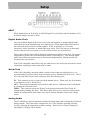
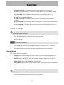
AES/EBU
When installed into an X-48 Slot, an AES/EBU digital I/O card will provide 24 channels of
I/O at normal sample rates (44.1k, 48k) or double speed sample rates (88.2k, 96k).
Note: Use only DB25 cables specified by the manufacturer as "AES/EBU" cables.
Many cables look the same on the outside.
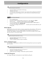
The AES/EBU DB-25 pinout is pictured :
14
Setup
ADAT
When installed into an X-48 Slot, an ADAT digital I/O card will provide 24 channels of I/O
at normal sample rates (44.1k, 48k).
Digital Audio Clock
Any time multiple digital audio devices are connected together, or multiple digital audio
connections are used simultaneously on a single device, all the digital audio clock rates of
the connected devices must be locked together. If this is not done, or if it is done
incorrectly, clicks, distortion, or muted audio may result. The X-48 may act as the master
clock to other devices in a system, or it can lock its clock to an external device.
This section will only deal with the physical connections to achieve clock lock. For system
configuration, please refer to Section 'Digital Audio Clock'(Page 22). Note that all digital
audio clock related connections may be connected simultaneously, with the needed one
selected in the user interface.
If the X-48 is digitally connected to only one other device, the clocks may be locked via that
connection, requiring no other connection be made.
Word Clock
If the X-48 is digitally connected within a system of more than two digital devices, it is
recommended to use Word Clock from one master source, distributed to all devices. The X48’s rear panel BNC Word Clock connectors have the following uses:
IN – This connector receives word clock from another device. When used, the X-48 should
be configured to lock to Word Clock.
OUT – This connector transmits word clock to other devices. When used, the X-48 should
be configured to Internal Clock.
THRU – This connector passes the Word Clock signal present at the Word Clock IN
through without adding any delay. This allows three devices to be locked in a daisy-chain
fashion in configurations where there is no way to directly distribute clock from a single
source.
Analog Audio
The IF-AN24X provides 24 channels of balanced analog inputs and 24 channels of balanced
analog outputs. The X-48 can be configured to one of five possible operating reference
levels by applying the appropriate software settings. Please refer to Section 'Analog I/O
Operating Level'(page 24) for details.
15
Setup
Note: Use only DB25 cables specified by the manufacturer as "Analog" cables.
Many cables look the same on the outside.
The analog DB-25 pinout is pictured below:
Synchronization and Control
This section will deal with the physical connections needed in various synchronized
applications. For details about the appropriate software settings, please refer to Section
'Synchronization'(page 45).
MIDI
There are two MIDI connectors on the rear of the X-48. These are used for MIDI Machine
Control (MMC) and MIDI Time Code (MTC).
IN – This connector receives MTC, which the X-48 can chase, or MMC, which the X-48
can respond to. The front panel MIDI LED will illuminate when valid MIDI signals are
present at this connector.
OUT – This connector outputs MTC any time the transport is in motion. That MTC output
follows the frame rate and output options set for LTC output.
Time Code
There are two ¼” TRS connectors on the rear of the X-48, used for sending & receiving
time code (LTC). These connectors are balanced to allow for long cable runs with minimal
interference. Please refer to page 48-52 for details on time code options.
Footswitch
A normally-open, momentary footswitch may be connected to this ¼” TS connector for
hands free transport and recording operation. NOTE: To operate correctly, as footswitch
must be connected before the X-48 is powered on.
Remote (Sony 9-Pin)
This is also known as “P2” or “Sony P2” or “RS-422”. Various recording consoles and
video controllers support this protocol for transport control and track record enable. This
16
Setup
requires a specifically constructed cable. If in doubt, pre-made RS-422 cables are readily
available.
1 : GND
2 : TX3 : RX+
4 : GND
5 : NC
6 : GNC
7 : TX+
8 : TX9 : FGND
Video Reference (Tri Level Sync)
IN – When the X-48 is used in a film/video post production environment, it may be
necessary to resolve a consistent sample range with the time code edge. A video reference
(blackburst) signal applied to this connector makes this possible. Please refer to page 48 for
details on configuring the use of signals present at this connector.
Tri Level Sync is the video reference signal used for High Definition Video. This connector
automatically senses the type of signal present.
THRU – The video reference signal present at the IN connector is passed through out this
connector without additional processing delay. This allows for daisy-chaining another
device, after the X-48, which requires a video reference signal.
Keyboard, Mouse & Monitor
A standard PC keyboard & mouse (or trackball) may be connected to the P/S2 or USB ports
on the rear of the X-48. To take full advantage of these peripherals, it is recommended that
a full keyboard with numerical keypad and a scrolling wheel mouse be used.
NOTE: The extra controls present on some multi-media keyboards, such as media player
transport controls, are not supported by the X-48. Similarly, a mouse or trackball that
depends on the installation of custom driver software is not supported by the X-48.
Your monitor should be capable displaying a resolution of at least 1024x768
pixels at a refresh rate of at least 60 Hz. The maximum resolution of the X-48's
display output is 2048x1536 pixels.
Network
The X-48 is equipped with two separate Network connectors on the rear panel. One is a
10/100 port and the other is a 10/100/1000 (Gigabit) port. The 10/100 port is pre-configured
as a DHCP port. The Gigabit port may be configured by the user in the X-48’s software.
Network cable used for these ports should be minimally CAT-5. While network hubs and
switches can be used with the X-48, such devices may reduce network throughput,
particularly on a network with much traffic.
When using the pre-installed MX-View software to control MX-2424 machines, the Gigabit
port must be used and configured to the correct IP address to communicate with the MX2424s.
17
Setup
For more details about software configurations to use the X-48 within a networked
environment, please refer to Section 'Networking'(page 26).
External Drives
External hard drives may be connected to the FireWire or USB 2.0 ports on the rear of the
X-48 to be used as record destination or copy destination drives.
When recording to any external drive, it is strongly recommended to run the
Drive Benchmarking utility to ensure the drive is fast enough for the desired number of
record tracks. For example, while FireWire itself is fast enough for high track counts,
the actual drive inside an external FireWire enclosure may be a low RPM drive, not
capable of high track counts.
USB Flash Drives, “Thumb Drives”, may be connected to an X-48’s USB port. Such drives
can be useful as source drives for copying material onto the X-48’s drive, copy destination
drives for moving material off an X-48, or for software updating. It is not recommended to
record directly to such a drive due to their slow write speeds.
External optical drives (DVD, CDR, CDR/W) drives are not supported.
Powering On / Off
Now that things are connected, it’s time to plug in the X-48 and power it on.
The X-48 is equipped with a universal power supply that is compatible with any country’s
voltage and frequency. It is not necessary to change any power settings when traveling
internationally with your X-48, though you may have to obtain an adapter to the local plug
configuration.
Momentarily press the POWER button on the front panel and the X-48 will boot up. The
boot process takes about 1 ¼ minutes to complete. When ready, the X-48 will display its
track screen on a connected VGA monitor and the currently loaded project with time code
on the front panel LCD display.
To power off the X-48, either select Shutdown from the File menu in the VGA UI or
momentarily press the front panel POWER button. In either case, you will be prompted to
save the currently loaded project then confirm the shutdown.
External Applications
While the X-48 is based on PC/Windows architecture, it is not configured for
general PC use. The Windows Embedded operating system used on the X-48 does not
include general use components. We strongly advise you not to install non-qualified
software on the X-48. Doing so could lead to undesirable results, including X-48
malfunction, requiring you to use the X-48 System Restore CD to restore it to its
original factory configuration.
18
Setup
MX-View
Pre-installed on the X-48 is MX-View Version 1.40, for control of any existing MX-2424
machines you may have. For MX-View operational instructions, please refer to the MXView Manual.
TASCAM Mixer Companion
Pre-installed on the X-48 is TASCAM Mixer Companion Version 1.30. This allows the X48 to act as the host computer for TMC when connected via USB to a TASCAM DM-3200
or DM-4800 digital mixer.
TMC updates may be installed by running the TMC update installer by selecting Launch
External Application from the X-48’s File menu. The TMC update installer would have to
be on a piece of media that the X-48 has access to, such as a CD or USB flash drive.
Only Version 1.20 or higher (Windows version) is designed to operate on the X48. Earlier versions of TMC should not be installed on the X-48.
VST Plug-ins
At the time of this writing, the following plug-ins have been qualified for installation & use
on the X-48. Please check the TASCAM web site for updates.
•
•
Waves 5 (using the iLok key)
Antares Auto Tune 4
Using the X-48 System Restore CD
In the event it becomes necessary to use the X-48 System Restore CD to restore your X-48
to its original factory configuration, following the steps below will ensure a smooth restore
process:
1.
2.
3.
4.
Back up all audio data. This should already be done as part of a regular workflow.
Ensure you have backups of any X-48 software installers or patch updates you may
have downloaded from the TASCAM web site.
With the X-48 powered on, insert the System Restore CD then restart the X-48. The
VGA UI doesn’t have to be displayed, all that is required is power to open the drive
tray. If necessary, the X-48 can be forced to shut down by holding the front panel
power button for a few seconds.
The X-48 will automatically boot from the System Restore CD and run the X-48
Installer. Please follow the steps in the X-48 Installer screens.
19
Configuration
Configuration
Configuration
This section helps you with the software settings you'll need to make in order for the X-48 to
work smoothly in your application.
Display Settings
Mouse/Keyboard Operation
Your monitor should be capable displaying a resolution of at least 1024x768
pixels at a refresh rate of at least 60 Hz. The maximum resolution of the X-48's
display output is 2048x1536 pixels.
You change the display resolution from the Windows menu:
•
•
Click the Windows menu and select Display Settings...
Move the slider to change the display resolution (the minimum resolution is 1024 x
768) and press Apply.
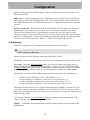
Navigating the LCD Interface
Front Panel Operation
To access menus and settings from the X-48 front panel, use the six buttons directly below
the LCD display:
•
•
•
•
•
•
Press one of the seven menus on the bottom right corner of the unit: PROJ, DISK,
I/O 1-24, I/O 25-48, SYNC, PREF or SYS. See below for an explanation of each of
these menus.
Press the Up/Down buttons to scroll through menus.
When you find a setting you want to edit, press CHNG (Change).
Press the Up/Down buttons to choose a setting.
When you're finished, press ENTER to save or EXIT to cancel your edit.
At any time, you can press HOME to get out of the menu system and back to the
main screen.
The seven menu keys are used to access the following functions:
•
•
•
PROJ: Goes directly to the list of project management functions such as New, Open,
Save, Save As, Delete and Copy.
DISK: Goes directly to the list of hard drive management functions such as a Free
Space display and disk formatting utility.
INP 1-24: Goes directly to input routing menus for inputs 1 through 24. In most
cases, these will be left at their default settings since much output routing can be
done from a recording console. The choices presented in this menu allows the use of
consoles with less than 48 outputs.
20
Configuration
•
•
•
•
INP 24-48: Goes directly to input routing menus for inputs 25 through 48. In most
cases, these will be left at their default settings since much output routing can be
done from a recording console. The choices presented in this menu allows the use of
consoles with less than 48 outputs.
SYNC: Goes directly to the list of synchronization settings & functions such as time
code frame rate, digital audio clock settings and time code chase options.
PREF: Goes directly to a list of general operating preferences for the X-48 such as
transport options, pre/post roll options, front panel UI options and external control
options.
SYS: Goes directly to a list of system settings such as save/load of user
configurations and network settings.
Sample Rates
The X-48 supports the base sample rates of 44.1k, 48k, 88.2k and 96k. The sample rate for
your project should be set immediately after creating the project and before recording any
audio. New projects will be created at the currently set sample rate by default. A project’s
sample rate is stored as part of the project.
If a project’s sample rate is changed after recording audio into that project, a confirmation
dialog will be presented. Proceeding with the sample rate change will cause the project to
play back faster or slower than it was originally recorded.
You will notice many other sample rates in the list besides the four noted above. Those are
“pull up” and “pull down” rates for use in film and video applications. This will be covered
in Section 'Synchronization'(page 45).
To set the sample rate:
Mouse/Keyboard Operation
•
•
•
•
Click on the Windows menu and choose Settings...
Click on the Sync tab.
Click on the Rate pull-down menu under Sample Clock.
You will see the currently selected sample rate with a check mark. Select another
sample rate by clicking on it.
•
•
•
•
•
Press SYNC
Use the Up or Down Arrow key until you see Sample Rate
Press CHNG
Use the Up or Down Arrow key until you see your desired sample rate
Press ENTER/YES
Front Panel Operation
21
Configuration
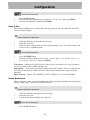
Digital Audio Clock
When digitally connected, two or more pieces of audio equipment must be running at
exactly the same digital audio clock rate and have their sample exactly lined up. If this is
not done, audio artifacts like clicking and popping or completely muted audio will result.
The X-48 provides the ability to operate in many digital audio clock scenarios. Each
available setting is shown below along with an example of why it may be used. These
settings are made on the Sync tab of the Settings window.
Internal – When selected, the X-48’s digital audio clock is running on its own at the
selected sample rate. Choose this when the X-48 is connected to an analog mixer or when
the X-48 is the clock master for other pieces of digital audio equipment.
Varispeed – The term “varispeed” refers to a recorder’s ability to run faster or slower than a
base rate. This may be used to record off speed for later playback at normal speed for a
special effect. It can also be used to slightly alter the pitch of a recording for tuning
purposes. Varispeed is only available when the X-48 is set to Internal clock. When clocked
externally, the X-48 must follow the rate of that external clock.
Word Clock – When selected, the X-48’s digital audio clock will be locked to any word
clock signal present at its BNC Word Clock input. If this is selected, but no word clock
signal is present, the sample rate indication in the GUI and the Sample Lock LED on the
front panel will flash indicating no clock lock.
Word clock is commonly used when many pieces of digital audio gear are connected
together in a system and clock is correctly distributed from a central clock generator or one
of the connected devices.
Invert Word Out Polarity – Some manufacturers of digital audio equipment lock to the
rising edge of a clock signal while others use the falling edge. This setting allows the X-48
to operate as a clock master with either type of equipment. This may not be documented by
all manufacturers, so if your clock configuration appears correct but you are still hearing
artifacts such as clicks, try changing the value of this setting.
Clock Rate Multipliers – Some older word clock generators only support base clock rates
(44.1k, 48k). For scenarios where such a clock generator is used in a system running at
higher clock rates, the X-48 provides the ability to lock to, and output, word clock rates that
are exact multiples of its operating rate. For example, a system may be running at 96k, but
the clock generator’s maximum output rate is 48k.
ADAT Card/AES Card(1, 2) – When selected, the X-48’s digital audio clock will be
locked to the digital audio signal present at the first group of eight inputs of a digital I/O
card installed in the specified slot. This would typically be used when the X-48 is digitally
connected via one of its slots to one other piece of equipment such a mixer or another
recorder.
S/PDIF – When selected, the X-48’s digital audio clock will be locked to the digital audio
signal present at the rear panel S/PDIF input. This would typically be used when the X-48 is
22
Configuration
digitally connected to the S/PDIF output of a piece of equipment when transferring stereo
audio into the X-48.
TDIF Port 1 – When selected, the X-48’s digital audio clock will be locked to the digital
audio signal present at the first TDIF port (1-8). This would typically be used when the X48 is digitally connected via TDIF to one other piece of equipment such a mixer or another
recorder.
Resolve to Video In – When checked, the X-48 will align the frame edge of its timecode
with the edge of the video reference signal. This is not used as a sample clock source.
Check this box when the X-48 is synchronized via time code to devices such as video
recorders, cameras, or edit controllers and all devices are locked to the same video reference
signal (a.k.a. Blackburst). For more information on synchronization and working with film
or video, please see the section in Chapter 3, "Video Clock Frame-Edge Resolve."
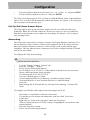
I/O Settings
This section explains how to configure the optional I/O cards for the X-48:
Mouse/Keyboard Operation
Choose Settings from the Windows menu and click on the I/O tab:
I/O Cards – At the top of the display, you'll see a list of installed optional I/O cards (if any)
I/O Setup – Using the I/O Card Select menus, you can select Input and Output types in
groups of eight from the selection pull down menus. (They are all set to TDIF by default.)
The Input Routing pull down menus set track input sources in groups of eight. They can be
used to configure the recorder inputs for a console that has less than 48 routing outputs.
For example, a console with 24 TDIF outputs could be connected to the X-48 this way:
•
•
•
•
Connect console TDIF outs 1-24 to X-48 TDIF in 1-24
Set Input Routing for channels 1-8 and 25-32 as Input Group 1 1-8
Set Input Routing for channels 9-16 and 33-40 as Input Group 2 9-16
Set Input Routing for channels 17-24 and 41-48 as Input Group 3 17-24
This allows all 48 tracks to receive signal without physical re-patching. Console out 1 will
feed track 1 and 25, console out 2 will feed tracks 2 and 26, etc. There is a track-by-track
input selection pull down menu in the Edit/Track screen which over-rides the selection made
in the Settings window.
You can also select the I/O operating level from the pulldown menu at the bottom of the
window. See the next section for more information.
S/PDIF – A checkbox at the bottom of the window enables sample rate conversion on the
S/PDIF input
23
Configuration
Front Panel Operation
To configure the I/O cards from the front panel:
•
•
•
•
Press the INP 1-24 or INP 25-48 key
Use the Up/Down buttons to select a bank of 8 inputs and outputs, i.e. "IO Card
Select 1-8" and press CHNG.
Select either TDIF 1-8 or Slot1 (1-8) and press ENTER.
Press the EXIT button when you are finished changing physical I/O types
To send a different bank of inputs to tracks, for example send inputs 1-24 to 25-48 (see
example above):
•
•
•
•
Press the INP 1-24 or INP 25-48 key
Use the Up/Down buttons to select routing for a bank of tracks, such as "Input
Routing 25-32" and press CHNG.
Select a bank of inputs, i.e. Input Grp1 1-8 and press ENTER.
Press the EXIT button when you are finished changing input groups
Analog I/O Operating Level
You can set the Analog Operating level from the Settings menu. Choose Settings from the
Window menu, click the I/O tab and click the I/O Operating Level from the pull-down
menu. Your choices are -9, -14, -16, -18 or -20dBfs.
Control Mode
The X-48 has four options for transport control:
Internal – The default is local control from the transport, mouse and keyboard
SMPTE – When enabled and the front panel TC CHASE key is enabled, the X-48 chases
the SMPTE timecode from its input jack.
MIDI (MTC) – In this mode with the front pantl TC CHASE key enabled, the X-48 chases
incoming MIDI timecode from it's MIDI input.
Theater Play – This is a special playback mode similar to Auto Cue on a CD Player. Please
refer to Page 49 for details on the use of this mode.
MIDI Device ID
When working with MIDI Machine Control, you can set a MIDI device ID so that other
devices don't intercept commands for the X-48 (and vice-versa). To set the MIDI device ID:
Mouse/Keyboard Operation
•
•
•
Click the Windows menu, select Settings and click the System tab
Click the MIDI Device ID pulldown
Select a device ID from the list
24
Configuration
Front Panel Operation
•
•
•
Press the SYS button
Press the Up/Down buttons to select Midi Device ID and press CHNG
Select an ID from the list and press ENTER
Sony 9-Pin
This section explains how to control the X-48 using Sony 9-pin, also called P2 or RS-422.
To access these settings:
Mouse/Keyboard Operation
•
•
•
Click the Windows menu and select Settings
Click the Prefs tab
There are three settings under the Sony 9-pin heading: Track Arm, Punch Delay and
Chase Control, explained below.
Front Panel Operation
•
•
Press the PREF button
Press the Up/Down buttons to select P2 Track Arm, P2 Punch Delay or
P2 Chase Control and press CHNG
Track Arm – Setting it to Digital/Console allows you to arm tracks over 9-pin. Set this to
Local if you don't want to arm tracks this way.
Punch Delay – You can set the punch-in delay from off to 6 frames. This is used when it is
necessary for the X-48 to emulate an older video deck to match what is expected by the
controller.
Chase Control – Choose LTC (SMPTE) or MTC (MIDI) here, or it can be disabled.
Video Reference
When working in video, use video blackburst to align your audio playback and time code to
exactly a frame edge. To switch on video reference:
Mouse/Keyboard Operation
•
•
•
Click the Windows menu and choose Settings
Select the Sync tab
Check the box labeled Resolve to Video In
Front Panel Operation
•
Press the SYNC button
25
Configuration
•
•
Press the Up/Down buttons to select Resolve to Video In and press CHNG
Use the Up/Down buttons to select On and press ENTER
The Video Clock input supports Tri-Level Sync for High Definition Video. If the blackburst
input is Tri-Level, the X-48 automatically enables this feature. See Chapter 3, Recording for
more on sample clock and video sync.
Pull Up/Pull Down Sample Rates
The X-48 supports pull-up and pull-down sample rates for use in film and video postproduction. When you select the sample rate for the new session, be sure to consider the
final delivery format and set your sample rate accordingly. See Chapter 3, Recording for
more on sample rates.
Networking
The X-48 can be connected to a computer using the fast Gigabit Ethernet connection. You
need an Ethernet crossover cable to connect your computer to the X-48, unless you know
that your computer's Ethernet connector is "auto-sensing" (such as most modern Apple
computers). Once the ethernet cable is connected, you need to configure both the X-48 and
your PC for networking:
To configure the X-48 for networking:
Mouse/Keyboard Operation
•
•
•
•
•
•
•
•
•
•
View the "Settings" window, "System" tab.
Press the "Configure..." button.
Select "Use the following IP address".
Set "IP address" to be 192.168.1.1. If this address is already in use by your router,
choose a different number for the last digit.
Set "Subnet mask" to be 255.255.255.0.
Leave the "Default gateway" blank.
"Use the following DNS server addresses:" should be already selected.
"Preferred DNS server" and "Alternate DNS server" should be blank.
Press OK.
Begin sharing the X-48's hard drive by selecting "Drive Sharing..." from the File
menu.
To configure your Windows XP computer for networking to the X-48:
•
•
•
•
•
•
Select Start->Control Panel->Network Connections.
You should see a list of network connections, with one called "Local Area
Connection".
Right-click on "Local Area Connection" and select "Properties".
Click on "Internet Protocol (TCP/IP)" so that it is highlighted. (Its check box must
remain checked.)
Press the "Properties" button.
Select "Use the following IP address".
26
Configuration
•
•
•
•
•
•
•
•
•
•
•
•
•
•
•
•
•
Set "IP address" to 192.168.1.2. (Note: This is different from the X-48's IP address.)
If this IP address is already in use on your network, pick a different number for the
last digit.
Set "Subnet mask" to be 255.255.255.0.
Leave the "Default gateway" blank.
"Use the following DNS server addresses:" should be already selected.
"Preferred DNS server" and "Alternate DNS server" should be blank. Press OK.
Close the "Local Area Connection Properties" window.
Select Start->My Network Places.
On the left side of the "My Network Places" window is a list of "Network Tasks".
Select "View workgroup computers". If this left side display is not visible, enable it
by going to Tools > Folder Options > General tab and click “Show common tasks in
folders”. Alternatively, you could double click “Entire Network” then “Microsoft
Windows Network” to see the available workgroups. Inside the workgroup named
“Workgroup” will be the X-48. If your computer and X-48 workgroup names are
different, navigate one level up to see all the workgroups present on the network and
look inside WORKGROUP to find the X-48.
Your X-48 will show up similar to this: "X48-uo0t97er5vk". (It is possible that you
may need to wait a minute or so for the X-48 to show up in this list.)
Note that the X-48’s workgroup name is fixed as “WORKGROUP”. Your PC’s
network name may not be WORKGROUP. For example, Windows XP Home has a
default network name of “MSHOME”. To find the workgroup name of your
computer go to Control Panels > System > Computer Name tab.
Double click on the icon that represents the connected X-48.
You should be prompted to enter a user name and password.
The user name is "administrator" and the password is "admin".
Now when you double click on the icon, you should be able to see the X-48's
internal hard drive. It is called "X48 Data Drive".
Double-click on "X48 Data Drive" to see its contents.
Look in the "XProjects" directory for projects.
To configure your Mac OS X computer for networking to the X-48:
•
•
•
•
•
•
•
•
•
•
•
Click on System Preferences... under the Apple menu and choose Network.
(Optional:) You may want to make a new Location under the Location pull-down
menu.
Double-click on Built-In Ethernet
Click the Configure IPv4 pull-down menu and choose Manually.
Set IP Address to 192.168.1.2. (Note: This is different from the X-48's IP address.) If
this IP address is already in use on your network, pick a different number for the last
digit.
Set Subnet Mask to be 255.255.255.0.
Leave Router, DNS Servers and Search Domains blank.
Click Apply Now and close the window.
Open a new Finder window and click the Network globe on the left side of the
window.
Your X-48 will show up similar to this: "X48-uo0t97er5vk". (It is possible that you
may need to wait a minute or so for the X-48 to show up in this list.)
Double click on the icon that represents the connected X-48.
27
Configuration
•
•
•
•
You should be prompted to enter a user name and password. The user name is
"administrator" and the password is "admin".
The Finder will ask you which drive you want to mount. There is only one choice,
"X48 Data Drive". Click OK.
Double-click on "X48 Data Drive" to see its contents.
Look in the "XProjects" directory for projects.
If you're having trouble getting things to work, you should be able to "ping" the X-48 from
the PC. Open an MS-DOS window (Windows) or the Terminal in Applications/Utilities
(Mac OS X) and type “ping 192.168.1.1”. Note that this example uses the IP address
specified in the above steps. If the X-48 does not respond then you something is not
connected or configured correctly.
Checking Free Hard Drive Space
Prior to beginning a recording project, you'll probably want to check your available hard
drive space:
Front Panel Operation
•
•
•
•
Press the DISK button
Use the Up/Down buttons to select Free Space
Press the Up/Down buttons to see the free space on each of your drives.
Press HOME when you're finished.
Drive Benchmarking Utility
The X-48 includes a utility that you can use to test any connected drive before using it. The
recorder runs a series of write/read tests and then reports how many tracks it can record to
that drive at 48kHz and at 96kHz. You should run this when you attach a new hard drive to
the system, especially an external FireWire hard drive with an unknown drive inside it. To
run the Drive Benchmarking Tool:
Mouse/Keyboard Operation (only)
•
•
•
Click the File menu and choose Drive Benchmarking...
Choose your hard drive from the pull-down menu.
Click OK to start the test. In about a minute, the X-48 will report how many tracks
you can record to this drive at 48kHz and at 96kHz.
Formatting a New Drive
A new hard drive needs to be formatted before recording on the X-48. To do this:
Mouse/Keyboard Operation
•
Click the File menu and choose Disk Management...
28
Configuration
•
•
•
•
•
•
The X-48 warns you that it will shut down after running this application. Click Yes
(or No) to save your project first.
The next prompt warns you that you can do some serious damage by misusing the
Disk Management tool, such as modifying the C: drive. Click OK when you're ready
to begin.
The Disk Management tool opens. Disk0 should be the startup disk, partitioned into
the C: drive (your operating system and program files), and the D: drive (the Data
partition you can write to).
If you've connected a FireWire drive, you should see it mounted as Disk1. To format
this disk, right-click the bar on the right and select "Format."
Give the disk a name and click OK twice.
When you're finished, click the Close box in the top right corner. The X-48 will shut
down. Restart the recorder to begin using your drive.
Front Panel Operation
•
•
•
•
Press the DISK button
Use the Up/Down buttons to select Quick Format and press CHNG.
Select a drive using the Up/Down buttons and press ENTER.
The display will ask you if you want to format the drive. Press ENTER/YES.
Factory Defaults
This section tells you how to restore the X-48 to factory defaults:
Mouse/Keyboard Operation
•
•
•
Open the Windows menu and select Settings
Click the System tab
Click the System Settings Reset button. The recorder will ask you if you want to
restore the X-48 to factory settings, click OK.
Front Panel Operation
•
•
•
•
Press the SYS button
Press the Up/Down buttons until you select Settings and press CHNG.
Select Recall Defaults using the Up/Down buttons and press CHNG.
The display will ask, Reset settings to factory defaults? Press
ENTER/YES.
Store/Recall User Settings
You can store your own settings for later recall. You might do this if you do multiple types
of sessions that require different configurations:
29
Configuration
Mouse/Keyboard Operation
•
•
•
•
Open the Windows menu and select Settings
Click the System tab
Click the System Settings Store button. Type a name for the settings and click OK.
To restore the system settings you've saved, click the Recall button and find your
backup.
Front Panel Operation
•
•
•
•
•
Press the SYS button
Press the Up/Down buttons until you select Settings and press CHNG.
Select Store... using the Up/Down buttons and pres CHNG.
Give your settings a name using the Up/Down buttons and the CHNG button to
cursor forward, then press ENTER/YES.
To recall your settings, select Recall... from the previous menu and locate your
backup file.
Mixer Bypass
Bypassing the mixer section improves inupt to output delay and and reduces CPU usage by
keeping the mixer EQ, level, etc. settings disabled when using the X-48 strictly as a
recorder. Mixer Bypass is switched on by default, so you'll need to disable it before using
the mixer section. To access this setting:
Mouse/Keyboard Operation (only)
•
•
•
Open the Windows menu and select Settings
Select the System tab
Check or uncheck the Mixer Bypass checkbox.
Make a Default Project
You can define a default project which has all of the routing and sync presets you typically
use. To do this:
Mouse/Keyboard Operation (only)
•
•
•
Open the File menu and select Save Project As...
Navigate to D:\XProjects\Startup\
Name your project "Startup". Click OK to replace the old file.
Install VST Plug-Ins
See Chapter 'Mixing' for information on using Third-Party Plug-Ins.
30
Recorder
Recorder
Working With Projects
Creating a New Project
Mouse/Keyboard Operation
•
•
•
Click on the File menu and select New Project... or press Control-N on the keyboard.
The display will ask you if you wish to save changes to the current the current
project. Click on Yes or No.
The display prompts you for the following information:
Name: Type a name for the project using the keyboard
Drive: Select which drive to record to
Mode: Either Non-Destructive or Destructive. See next section for explanation.
Sample Rate: The sample rate for the session. Most users will choose either
44.1k (CD-standard), 48k (DAT-standard), 88.2k (2x CD) or 96k (2x DAT). A
number of other sample rates are provided for post production use. See Section
'Sample Rates'(page 46) for more information on when to use these sample rates.
Bit Depth: Choices of 16-bit, 24-bit, or 32-bit Floating Point are provided.
•
Click OK when complete.
Front Panel Operation
•
•
•
•
•
On the front panel of the X-48, press the PROJ button, press the Up/Down arrows to
select New and press CHNG.
Press the Yes or No button to save the current project.
Choose a drive to record to with the up/down buttons and press ENTER.
Select the bit depth – either 16-bit, 24-bit or 32-bit floating point – and press Enter.
Give the project a name using the Up/Down buttons to change letters, the Change
button to select the next letter. Press Enter to create the project or EXIT to cancel.
Destructive versus Non-Destructive Recording
The X-48 provides two methods for recording, Non-Destructive (the default) and
Destructive.
When Non-Destructive recording is selected, new recordings are written to the hard drive
as new WAVE files. With this method, you can return to an old take of a recording using
Undo or by editing the previous take. The disadvantage to this method is that your hard
drive is filled with Wave files. If you imported all of these files into a digital workstation,
31
Recorder
you may not be able to tell which was the final approved recording unless you had exported
an AAF file as well.
Using Destructive recording is just like using a multitrack tape, and is often referred to as
"tape mode." If you look at the hard drive after recording this way, you will see one long
WAVE file for every track that you recorded to. Film re-recording mixers use destructive
recording to record their final mixes. As they punch in and out of their mix recorder all day,
they only want one master file of the approved mix to encode into Dolby Digital or however
it's being processed for release. Destructive recording also has the advantage that it uses less
hard drive space, since old takes aren't kept. But just like the multitrack tape it emulates,
when you record over something it's gone forever. There's no undo in destructive recording
mode.
Opening a Project
Mouse/Keyboard Operation
•
•
•
•
Click on the File menu and select Open Project... or press Control-O on the
keyboard.
The display will ask you if you wish to save changes to the current the current
project. Click on Yes or No.
The Open Project window appears. At the top of this window, click the Up button to
navigate up a level on your hard drive, or all the way up to see all drives connected
to the system.
Double-click on the folder containing your project. You should see a project with the
filename you chose ending in a ".ndr" extension. Double-click on this file to open the
project.
Front Panel Operation
•
•
•
•
On the front panel of the X-48, press the PROJ button, press the Up/Down arrows to
select Open and press CHNG.
Press the Yes or No button to save the current project.
Choose a drive
Select the file to open using the Up/Down buttons and press ENTER, or EXIT to
cancel.
Saving a Project
Mouse/Keyboard Operation
•
Click on the File menu and select Save Project... or press Control-S on the keyboard.
32
Recorder
Front Panel Operation
•
On the front panel of the X-48, press the PROJ button, press the Up/Down arrows to
select Save and press CHNG.
Saving Your Work
How often do you need to save? The X-48 writes data to the drive during recording. You
should periodically save during recording, and whenever you change something in the
mixer. You may also want to switch on Auto Save, described below. However, if the X-48
loses power during a long recording, the Wave files can be re-imported when you switch it
back on. For best results and piece of mind, save early and often.
Auto-Saving Projects
You may want to enable auto-save so that your recordings and mixes are saved in the event
of a power outage.
Mouse/Keyboard Operation
•
•
•
Click on the Windows menu and select Settings, or press Shift-F8 on the keyboard.
Select the Prefs tab.
Click the Auto-save Projects checkbox. You can specify how often the machine
saves, from every 1 to 120 minutes.
Front Panel Operation
•
•
•
•
•
On the front panel of the X-48, press the PREF button.
Press the Up/Down arrows until you select Auto Save and press CHNG.
Press the Up/Down buttons to select On and press ENTER.
Press the PREF button again, press the Up button once to select Auto Save
Time and press CHNG.
Change the Auto-save interval time (10 minutes is the default) and press ENTER.
Importing a Project
The X-48 can import an Open TL project. This function can only be accessed form the
mouse and keyboard – it's not possible to import a file using the front panel LCD.
Mouse/Keyboard Operation (only)
•
•
To open this project, select Import Project... from the File menu.
The recorder will prompt you to save your project, click either Yes or No.
33
Recorder
•
Select a project to import using the window interface. You can navigate up to select
another drive. Click Open or Cancel to select a project.
Exporting a Project
The X-48 can export the recording project as either an AAF file (Advanced Authoring
Format) or an Open TL file. AAF files are supported by most digital audio workstations,
including Pro Tools, Logic and Nuendo. You may need additional software to import an
AAF file, such as DigiTranslator for Pro Tools. Consult your workstations documentation or
support website for more information. This function can only be accessed form the mouse
and keyboard – it's not possible to import a file using the front panel LCD.
Mouse/Keyboard Operation (only)
•
•
•
To open this project, select Export Project... from the File menu.
Using the Filter control at the bottom of the window, select either AAF or Open TL
as your output format.
You can navigate up to select another drive. Click Save to export the project.
Copying a Project
You can make a copy of a project with the X-48, for instance as a backup to another drive.
This copies the project and all of its wave recordings, unlike "Save As..." which only copies
the project file.
Mouse/Keyboard Operation
•
•
•
•
Click on the File menu and select File Manager or press Control-F on the keyboard.
You should see the File Manager window with two panes on the left and right. In the
left hand pane, navigate to the project folder you want to copy (containing the .ndr
file and Audio folder). Click on this folder so it's highlighted.
Using the controls on the right side, navigate to where you want to copy the project
to, i.e. a removable FireWire hard drive.
When you're ready to begin copying, press the >> button under the word Copy
between the two panes.
Front Panel Operation
•
•
•
•
•
On the front panel of the X-48, press the PROJ button, press the Up/Down arrows to
select Copy and press CHNG.
Press the Up/Down arrows until you select a source project folder and press ENTER.
Press the Up/Down arrows and select a project file(.ndr file) and press ENTER.
Press the Up/Down arrows and select a destination drive and press ENTER.
Enter a destination project name by using Up/Down arrows and CHNG button, and
press ENTER.
34
Recorder
Backing Up a Project to CD/DVD
There are three destinations for backing up a project: to the built-in DVD drive, to a
network, or to another hard drive. To back up to another hard drive, see the "Copying a
Project" instructions above. To copy a project to a connected network, see page 26 in the
chapter on Networking. This section explains how to back up to the built-in DVD recorder.
Mouse/Keyboard Operation (only)
•
•
•
•
Click on the File menu and select File Manager or press Control-F on the keyboard.
You should see the File Manager window with two panes on the left and right. In the
left hand pane, navigate to the project folder you want to back up (containing the
.ndr file and Audio folder). Click on this folder so it's highlighted.
In the center pane, click the Backup button.
The Burn Options window should appear. It will tell you how large the project folder
you selected is, and will give you the option to burn the project to a 650MB CD ,
700MB CD or 4.7GB DVD. You can also click a checkbox to verify the disk after it
has been burned.
Deleting a Project
Mouse/Keyboard Operation
•
•
•
•
Click on the File menu and select File Manager or press Control-F on the keyboard.
You should see the File Manager window with two panes on the left and right. In the
left hand pane, navigate to the project folder you want to back up (containing the
.ndr file and Audio folder). Click on this folder so it's highlighted.
In the center pane, click the Delete button.
In the Confirm Delete window that opens, click OK.
Front Panel Operation
•
•
•
•
On the front panel of the X-48, press the PROJ button, press the Up/Down arrows to
select Delete and press CHNG.
Press the Up/Down arrows to select a project folder and press ENTER.
Press the Up/Down arrows and select a project file(.ndr file) and press ENTER.
A confirmation message appears. Press YES/NO to execute/cancel the delete
operation.
Load Last Project
The X-48 can default to loading the last project used at startup. This is useful for working on
long-term projects, or when the X-48 is used as a playback device for live or theater use.
35
Recorder
Mouse/Keyboard Operation
•
•
•
Click on the Windows menu and select Settings or press Alt-F8 on the keyboard.
The Settings window will open. Click on the tab at the bottom of this window titled
Prefs.
At the top of the screen is a checkbox labeled Load Last Project on startup. Check
this box.
Front Panel Operation
•
•
On the front panel of the X-48, press the PREF button, press the Up/Down arrows to
select Load Last Project and press CHNG.
Use the up/down buttons to select On and press ENTER.
Transport Operations
Local
The X-48 has six transport buttons you should already be familiar with. These buttons are
found on the front panel and on the VGA display:
REW rewinds the transport. After rewinding for three seconds, it rewinds at a faster rate.
After another three seconds, faster still.
F FWD puts the transport in Fast-Forward. It moves at increasingly faster rates like the
Rewind button.
STOP stops playback, recording or loop playback.
PLAY starts playback, loop playback or loop recording
RHSL starts Rehearsal recording. This simulates recording (changing input monitor modes
as selected) without actually punching into record. It can also be used to set punch
in/out points.
REC starts recording when pressed at the same time as PLAY. It can start recording on its
own if One Button Record is set to on, see next section.
One-Button Record
This function allows recording to being when the record button is pressed by itself, instead
of requiring the record and play buttons to be pressed at the same time.
Mouse/Keyboard Operation
•
•
•
Click on the Windows menu and select Settings or press Alt-F8 on the keyboard.
The Settings window will open. Click on the tab at the bottom of this window titled
Transport.
At the top of the screen is a checkbox labeled One Button Record. Check this box.
36
Recorder
Front Panel Operation
•
•
On the front panel of the X-48, press the PREF button, press the Up/Down arrows to
select One Button Record and press CHANGE.
Use the up/down buttons to select On and press Enter.
TC Chase
The TC Chase feature allows your X-48 to chase incoming timecode.
Front Panel Operation
•
On the front panel of the X-48, press the TC CHASE button. The X-48 will chase
the timecode you've selected in the Sync Control Mode menu.
See the section titled "Synchronization" for more on timecode chase.
Rehearse
The Rehearse feature allows you to hear the effects of recording without actually recording
to disk. This feature is useful for testing auto-punch in and out points or for rehearsing talent
before recording.
Mouse/Keyboard Operation
•
Click on the REH button in the transport section in the top-right corner of the screen.
Front Panel Operation
•
Press the RHSL button on the front panel of the X-48.
Pre/Post Roll
The Rehearse feature allows you to hear the effects of recording without actually recording
to disk. This feature is useful for testing auto punch-in and -out points or for rehearsing
talent before recording.
Mouse/Keyboard Operation
•
•
•
Click on the Windows menu and select Settings or press Alt-F8 on the keyboard.
The Settings window will open. Click on the tab at the bottom of this window titled
Transport.
Click the checkbox labeled Enable Pre/Post-Roll. You can click on the fields for
pre-roll and post-roll to specify how many seconds you require.
37
Recorder
Front Panel Operation
•
On the front panel of the X-48, press the PREF button. Use the Up/Down buttons to
select Use Pre/Post-Roll and press CHNG.
Use the up/down buttons to select On and press Enter.
Pre-roll and Post-roll times can also be changed in the Preferences menu.
•
•
Varispeed
Varispeed playback changes the playback speed of the recorder, re-sampling at the output to
maintain the selected sample rate. It can be useful when an instrument cannot be tuned to
match a recording or to speed up or slow down a song's playback (while simultaneously
changing the pitch).
Mouse/Keyboard Operation
•
•
•
Click on the Windows menu and select Settings or press Alt-F8 on the keyboard.
Click the Sync tab.
Click on the checkbox labeled Varispeed Enable. Use the slider or click in the text
box to specify the amount of varispeed.
Recording and Playing Back
Input Monitoring
There are three options for input monitoring:
•
•
•
•
Normal input monitoring puts any track that's in record in input monitoring. Whether
the transport is in play, record or stop, you will hear the input only and not what is
recorded. This mode is typically used for tracking.
When the recorder is in Auto Input mode, you will hear the input when the transport
is in stop or record. When the transport is in play, you will hear what was previously
recorded. This mode is used for punch-in recording, so that the artist and engineer
can hear what was previously on the track before recording over a section of that
performance.
ADR Monitoring Mode is similar to Auto Input, but puts the track in input only
when the transport is in record. The track reverts to playback in stop or play to
prevent feedback.
All Input mode enables input monitoring for all tracks, whether they are armed for
recording or not. This mode is often used for live recording.
Mouse/Keyboard Operation
•
•
For Auto Input, click on the Options menu, scroll over the Auto Input submenu and
select On or ADR.
For All Input, click on the Options menu and select All Input.
38
Recorder
Front Panel Operation
•
•
To enable Auto Input, press the AUTO INPUT button on the front panel.
For All Input mode, hold the SHIFT button while pressing AUTO INPUT.
Putting Individual Tracks into Input
You can put tracks into input mode on a channel-by-channel basis.
•
•
From the Mouse/Keyboard interface, click the I button next to any track number.
From the front panel, hold the SHIFT button and press any track arming button.
Record Enable
Mouse/Keyboard Operation
•
Click on the R button to the right of the track numbers on the left side of the screen
in the Tracks view. The button will flash red to indicate it is ready for record.
Front Panel Operation
•
Press the Record Enable buttons on the front panel. The Record indicator will flash
on tracks that are ready to record.
Punch Crossfade Time
To avoid an audio click when punching in and out of record, the X-48 automatically fades
into and out of record. This crossfade time is very fast, but prevents an audio pop. The
crossfade time can be set between 0ms (disabled) and 90ms in increments of 10ms:
Mouse/Keyboard Operation
•
Click on the Windows menu and select Settings. Select the Prefs tab and click the
Punch Crossfades submenu. Select the desired crossfade time.
Front Panel Operation
•
Press the PREF button and use the up/down buttons to select Punch Crossfade. Press
the CHNG button, select the desired crossfade time using the up/down buttons and
press CHNG again.
39
Recorder
Undo/Redo
Unlike tape machines, you can undo a recording pass and then put it back with redo.
Undo/redo is only available from the mouse/keyboard interface.
Mouse/Keyboard Operation (only)
•
Click the Edit menu and choose Undo or press Control-Z on the keyboard.
Metering
Several metering parameters are available:
•
•
•
Peak Hold displays the highest signal level achieved, either for a few seconds or
until cleared.
Meters can be Pre-fader or Post-fader (not applicable in Mixer Bypass mode). This
means that the meters show the signal level either before or after the signal hits the
mixer interface.
(GUI only) you can View Masters to see the signal level for the group and aux
channels.
Mouse/Keyboard Operation
•
•
•
•
•
Click on the Meter button
if meters are not displayed at the top of the
screen.
Click on the Options menu and select the Meters submenu. From this submenu you
can select Peak Hold and Clear Overloads.
Click on Options > Meters > Mode to select Pre-Fader or Post-Fader metering.
Click on Options > Meters > View Masters to see the group and aux master levels, or
click on the on-screen meters themselves.
To set the amount of time that peak values stay on the meters, click Windows and
select Settings. Click on the Prefs tab and change the Clear Overloads pulldown to
change the interval to 1 second, 5 seconds, 30 seconds or Hold (infinite).
GUI Meter Display
You can display the meters by clicking the bargraph icon in the center of the screen
or by pressing 1 on the keyboard.
Front Panel Operation
•
Press the PREF button and scroll to the Meters sub-menu and press CHNG.
40
Recorder
•
•
•
Select Meter Mode and press the CHNG button to switch between Pre-Fader
(the default) and Post-Fader.
Select Meter Range and press the CHNG button to switch between -oo to
0dB (minus infinity to 0dB, the default) -24dB to 0dB or -12dB to 0dB.
These fine dB scales can be useful when sending test tones to the recorder, such as
for aligning the analog I/O card or a Dolby encoder.
Select Peak Hold to switch this function on or off.
Using Markers
Markers allow you to label sections of a recording for visual reference and to locate back to
later.
Mouse/Keyboard Operation
•
•
To create a marker, click the Edit menu and select New Marker or press the Enter
key on your keyboard's number pad.
To access a memory location, open the Markers window from the Windows menu.
From here you can select a memory location, rename it and locate to it.
Loop Playback
You can loop a section of the timeline for playback or recording. The loop plays back (with
preroll and postroll settings, if assigned) until the stop button is pressed.
Mouse/Keyboard Operation
•
Drag the loop start and stop points to the location you want them. The loop markers
are blue triangles that fill the entire height of the timeline ruler, and are at 0:00:00:00
by default.
•
•
Click the loop button
Press Play.
to turn on the loop function.
Loop Mode
The X-48 has three Loop Modes:
•
•
•
Play Once and Cue plays through the loop once, then locates to the beginning of the
loop (or pre-roll point if enabled) and stops.
Play Once and Stop plays through the loop once and then stops at the loop end (or
post-roll point if enabled).
Play Repeatedly plays through the loop, locates to the beginning of the loop (or
preroll point if enabled) and plays again, repeating until the stop button is pressed.
By default, the Loop mode is set to Play Once and Cue. To change this behavior:
41
Recorder
Mouse/Keyboard Operation
•
•
•
Click on the Windows menu and choose Settings.
Select the Transport tab.
The submenu titled Loop Mode has the three choices explained above.
Front Panel Operation
•
•
Press the PREF button. Press the up/down buttons until you select Loop Mode
and press CHNG.
Select one of the three choices explained above and press Enter.
Auto Punch
The Auto Punch function automatically drops into and out of record when switched on. This
is used to automate a difficult punch in and out, such as one word in a lead vocal or an ADR
(automated dialog replacement) line that will be attempted several times.
Mouse/Keyboard Operation
•
•
•
First, set the punch in and punch out points. By default, these are set for the last
place you manually punched in and out. (You can disable this function by opening
the Settings window, click the Transport tab and uncheck Update Punch Points.)
You can also drag the punch in and out points in the timeline ruler, they're the red
triangles that fill the timeline ruler. You may want to zoom into a waveform and set
the markers manually if you're trying to replace or spot-erase some recorded audio.
Hold the Shift button and click the Record button on the onscreen transport to switch
on Auto Punch mode. The Record light will flash.
Move the transport to a location before the punch-in point and press Play. When the
transport reaches the punch-in point it will punch into record. When it passes the
punch-out point it will go into play again.
Front Panel Operation
•
•
•
First, set the punch in and out points. By default, the recorder remembers the last
timecode that you punched into and out of record and uses these for your punch in
and out points. (To change this behavior, open the Preferences menu, select Update
Punch Points and change that setting to Off.) You can use the Rehearse button
to punch in and out of record without actually recording to set new punch in and out
points.
To enter Auto Punch mode, hold the SHIFT button and press RECORD. The
Record light will flash.
Move the transport to a location before the punch-in point and press Play. When the
transport reaches the punch-in point it will punch into record. When it passes the
punch-out point it will go into play again.
42
Recorder
Loop Recording
You can also record while in loop mode. When you record in loop mode (and nondestructive recording is selected), a new audio file is written each time the recorder makes a
pass. You might use this feature when trying multiple successive takes of a guitar solo, for
example. To use the loop recording feature, turn on both Loop Playback and Auto Punch
and press Play. (See previous sections.)
Using the VGA Recorder Interface
Meters
The X-48 displays meters on the top of the screen by default. To show or hide these meters,
button in the middle of the display. For more about the on-screen meters,
click the
see Page 40, Metering.
Naming Tracks
Each of the tracks can be named for easy reference and for auto-naming recorded wave files.
To name a track:
Mouse/Keyboard Operation (only)
•
•
•
Click on the Tracks tab at the bottom of the screen or press F1.
Double click on the track-name on the left side of the screen, such as Track 1
Type a new name and press Enter.
Scrolling
You can control the way that tracks scroll on the X-48:
•
•
•
None means that playback will not change the view selected in the screen
Auto-Scroll means that the center line will remain stationary and the waveform will
move under that. The playback line needs to move to the center of the display first,
but once it "catches up" it will remain there.
Page Flip tells the playback line to scroll across the screen, then advance to the next
chunk of timeline and scroll across that. This is the default view for Pro Tools.
To change the scrolling behavior:
•
•
Click the Options menu and select Scrolling
Choose either None, Auto-Scroll or Page-flip
You can also click the Auto Scroll button in the top left corner of the Tracks display:
Timebar Format
The time ruler can be displayed in SMPTE time or in samples. To change this behavior:
43
Recorder
•
•
Click the Options menu and select Timebar Format
Choose either SMPTE or Samples
Clip Properties
To specify information about a clip, open the Clip Properties window:
•
•
•
•
Use the Smart tool to select a clip
Under the Windows menu, select Clip Properties... or press Control-2 from the
keyboard.
You can change the name of the file, specify an exact start and end point, or move
the clip to the timecode embedded in its Broadcast WAVE file or playhead position.
You can also specify a fade in and fade out time and shape from this window, mute
or lock the clip position
Another way to edit these values, without opening the Clip Properties window, is
to click the Info button in the display. A new panel opens up below the transport with the
same clip options.
Navigating the Timeline
There are several ways to change the playhead position:
•
•
•
•
Drag the bottom scrollbar left and right, then click in the track display to jump to that
position
Use the Fast Forward and Rewind buttons, either on-screen or on the front panel
Double-click the timecode position readout and type in a new location with the
keyboard
Use an external machine control device (see next section on Synchronization)
Status Displays
To the right of the menu displays, you should see a screen similar to the one above. This
shows, from left to right:
•
•
•
•
Current sample rate
Auto Input, All Safe and Timecode Chase status (blue when on)
DSP load – with several plug-ins loaded, this level may grow higher and slow down
your system
Project Name
Input Routing
There are two ways to route inputs to tracks:
Routing in groups of 8:
•
Select the Windows menu and click Settings
•
Click the I/O tab
44
Recorder
•
The Input Routing pulldown menu selects which bank of 8 inputs will feed the
selected tracks. For example, setting the Input Routing for tracks 25-32 to Input
Grp1 1-8 will route inputs 1-8 to tracks 25-32.
Routing by individual channels (this supercedes the groups of 8 above):
•
Click a track in the Tracks tab (F1)
•
Click the DSP button in the middle of the display (or press F6)
•
Click the Input pulldown menu and select an input from 1-48.
Synchronization
Requirements
In order to reliably synchronize the X-48 to another device, two references are required:
•
•
A location reference, typically SMPTE (LTC) timecode sent to the X-48's
Timecode Input or into the RS-422 (Sony 9-pin) Remote input. This tells the X-48
where in the timeline to go.
A clock reference, typically word clock sent to the X-48 through a BNC cable. This
tells the X-48 how fast to go once it gets to the right location.
The X-48 can be run without an external word clock source, but it will eventually drift out
of sync. (You can also use a digital audio signal such as AES/EBU as a clock source.) You
will also hear clicks and pops in the digital audio if your entire studio is not resolved to a
single master clock.
Note that video clock is available on the X-48, but it cannot be used as the reference clock.
Video clock is only updated 60 times per second, where word clock is updated 48,000 times
or more per second. Long cable runs can also cause video clock to go out of phase, which
may cause problems with digital consoles. Video clock on the X-48 is used to define the
frame edge of the SMPTE input.
•
•
•
•
•
Word Clock sets the playback speed. Once the SMPTE input tells the transport
where to go, the X-48 plays at the rate set by its Sample Clock source (Settings
menu, Source).
Video Clock gives a precise frame edge to the SMPTE timecode. Not available as a
clock reference.
SMPTE Timecode is used as a location reference, defining where in the timeline to
locate to.
MIDI Timecode (MTC) is sometimes used as a location reference with MIDI
sequencing software or computer-based DAW software
RS-422 remote receives transport commands such as play and record. It also carries
SMPTE timecode for location reference.
As these reference sources are all related, you can see the importance of making sure that all
of your devices are resolved to the same clock reference. Another way to look at sync on the
X-48 is to examine the order that things happen when the X-48 is online:
45
Recorder
1.
2.
3.
4.
5.
6.
The X-48 either sees a transport command from the RS-422 signal or sees SMPTE
timecode and goes into play.
The X-48 looks at either the SMPTE input or the RS-422 to figure out where in the
timeline to begin playback.
If enabled, the X-48 looks to the video clock input for a more exact timestamp for
the incoming SMPTE.
Once the X-48 is locked to the right SMPTE frame, it starts playing at the rate
dictated by its sample clock source.
If the incoming SMPTE isn't resolved to the same clock and drifts out of sync by a
difference greater than the flywheel setting, the X-48 stops.
When SMPTE timecode stops or an RS-422 stop command is received, the transport
stops.
Sample Rate
A sample rate should chosen when first creating a project, with consideration to what will be
done with the final product. Your choices are:
•
•
•
•
•
•
•
•
•
•
•
•
•
•
•
•
•
•
•
•
44100 (CD standard)
48000 (DAT standard)
88200 (2x CD standard)
96000 (2x DAT standard)
42336 (44.1k conversion from film (24) to PAL (25))
44056 (44.1k pull-down)
44144 (44.1k pull-up)
45938 (44.1k conversion from PAL (25) to film (24))
46080 (48k conversion from film (24) to PAL (25))
47952 (48k pull-down)
48048 (48k pull-up)
50000 (48k conversion from PAL (25) to film (24))
84672 (2x 44.1k conversion from film (24) to PAL (25))
88112 (2x 44.1k pull-down)
88288 (2x 44.1k pull-up)
91875 (2x 44.1k conversion from PAL (25) to film (24))
92160 (2x 48k conversion from film (24) to PAL (25))
95904 (2x 48k pull-down)
96096 (2x 48k pull-up)
100000 (2x 48k conversion from PAL (25) to film (24))
If you change the sample rate after audio has been recorded, that audio will play back at a
different pitch. To change the sample rate:
Mouse/Keyboard Operation
•
•
Click the Windows menu and select the Settings window.
Click on the Sync tab and click the Sample Clock Rate submenu. Choose a sample
rate from the list.
46
Recorder
Front Panel Operation
•
•
Press the SYNC button. Press the up/down buttons to select Sample Rate and
press CHNG.
Select a sample rate from the list using the up/down buttons and press Enter.
Clock Source
One of the most important settings on the X-48 is the sample clock source, which governs
playback speed and keeps audio pops from happening. There are five choices:
•
•
•
•
•
Internal is the default. This can be used if the X-48 is either used by itself, with an
analog console or as the master clock for the studio.
Word Clock should be used when you have an external, dedicated master clock
available. The word clock generator needs to be set to the same sample rate as the X48. (Note: the Word Clock input can accept a tri-phase signal from HDTV devices.)
S/PDIF clocks the X-48 from the digital audio signal coming into the S/PDIF Digital
Input.
TDIF Port 1 clocks the X-48 from the digital audio signal coming into the TDIF
Digital Input channels 1-8.
If you have digital audio option cards installed (IF-AD24(X) / IF-AE24(X) ), those
will show up as an available clock source as 'ADAT Card' / 'AES/EBU Card'.
When in doubt, use Word Clock as the reference source. To change the clock source:
Mouse/Keyboard Operation
•
•
Click the Windows menu and select the Settings window.
Click on the Sync tab and click the Source submenu. Choose your desired master
clock from the list.
Front Panel Operation
•
•
Press the SYNC button. Press the up/down buttons to select Sample Clock
Source and press CHNG.
Select a clock source from the list using the up/down buttons and press Enter.
BNC Clock In/BNC Clock Out
These parameters allow the word clock signal input or output to be multiplied or divided by
2, or used as-is. This allows, for example, a 48kHz word clock generator to be used when
recording at 96kHz, or allows 48k and 96k devices to be used at the same time. To change
these settings:
Mouse/Keyboard Operation
47
Recorder
•
•
Click the Windows menu and select the Settings window.
Click on the Sync tab and click the BNC In or BNC Out submenu. Choose a setting
from the list.
Front Panel Operation
•
•
Press the SYNC button. Press the up/down buttons to select BNC Clock In or
BNC Clock Out and press CHNG.
Use the up/down buttons to select a setting and press Enter.
BNC Word Clock Output Polarity
This setting allows the Word Clock signal output phase to be reversed. This may be
necessary in large systems or with long cable runs.
Mouse/Keyboard Operation
•
•
Click the Windows menu and select the Settings window.
Click on the Sync tab and check the box labeled Invert Word Out Polarity.
Front Panel Operation
•
•
Press the SYNC button. Press the up/down buttons to select Word Out
Polarity and press CHNG.
Use the up/down buttons to select either Normal or Inverted and press Enter.
Video Clock Frame-Edge Resolve
Video Clock in the X-48 can be used to define the frame edge of incoming and generated
timecode for stability and repeatability. (But not as a sample clock source, see Requirements
above.) To enable video clock:
Mouse/Keyboard Operation
•
•
Click the Windows menu, select the Settings window and click the Sync tab.
Check the box labeled Resolve to Video In in the Time Code area.
Front Panel Operation
•
•
Press the SYNC button. Press the up/down buttons to select Resolve to Video
In and press CHNG.
Press the Up/Down buttons to select On and press Enter.
Frame Rate
The X-48 syncs to any frame rate of SMPTE timecode:
48
Recorder
•
•
•
•
•
•
•
•
30-frame non-drop is occasionally used in music studios to sync console
automation to a tape machine (2" reel-to-reel tape may be striped with this format)
30-frame drop is rarely used
29.97 non-drop is the standard for non-broadcast post-production in the U.S.
29.97 drop is the standard for broadcast television post production in the U.S.
25-frame is the standard in Europe
24-frame non-drop is sometimes used for HDTV production or film location
recording
24.975 non-drop is 25-frame pull-down, used to play 25-frame videos on American
NTSC monitors
23.976 non-drop is "HD pull-down," used to play down-converted HD videos on
American NTSC monitors
To change the frame rate:
Mouse/Keyboard Operation
•
•
Click the Windows menu and select the Settings window.
Click on the Sync tab and click the Frame Rate submenu. Choose your desired frame
rate from the list.
Front Panel Operation
•
•
Press the SYNC button. Press the up/down buttons to select Frame Rate and
press CHNG.
Select a frame rate from the list using the up/down buttons and press Enter.
Control Mode
Four control modes are available:
•
•
•
•
Internal is the default setting, the X-48 controls its own transport and ignores the
SMPTE timecode input.
SMPTE follows the SMPTE timecode input for location, either from the RS-422
input or the balanced LTC input on the rear panel.
MIDI (MTC) looks to the MIDI input for timecode.
Theater Play plays a section of the timeline, stops, and waits for a Play command to
play the next section.
To change the control mode:
Mouse/Keyboard Operation
•
Click the Windows menu and select the Settings window.
49
Recorder
•
Click on the Sync tab and click the Control Mode submenu. Choose the desired
control mode from the list.
Front Panel Operation
•
•
Press the SYNC button. Press the up/down buttons to select Control Mode and
press CHNG.
Select a control mode from the list using the up/down buttons and press Enter.
Chase Freewheel
Chase Freewheel dictates how far out of sync the SMPTE timecode can drift before the X48 drops out of play or record. The choices are 0, 5, 10, 20, 50 or 100 frames. To change the
setting:
Mouse/Keyboard Operation
•
•
Click the Windows menu and select the Settings window.
Click on the Sync tab and click the Chase Freewheel submenu. Choose the desired
setting from the list.
Front Panel Operation
•
•
Press the SYNC button. Press the up/down buttons to select Chase Freewheel
and press CHNG.
Select a value from the list using the up/down buttons and press Enter.
Chase Relock
If the SMPTE drifts outside of the Chase Relock Threshold window (see next section), this
setting tells the X-48 what to do:
•
•
•
Always tells the transport to shift to the correct timecode value, even if it's in record.
Only if not recording shifts the transport in play but not in record.
Never ignores the slight timecode offset.
To change the re-lock setting:
Mouse/Keyboard Operation
•
•
Click the Windows menu and select the Settings window.
Click on the Sync tab and click the Chase Relock submenu. Choose a setting from
the list.
50
Recorder
Front Panel Operation
•
•
Press the SYNC button. Press the up/down buttons to select Chase Relock and
press CHNG.
Choose a setting from the list using the up/down buttons and press Enter.
Chase Relock Threshold
This parameter governs how far out of sync the X-48 can drift before the Chase Relock
feature forces it back in sync. (Or not, see previous section.) The range is 1/3 frame, 1
frame, 2 frames, 5 frames or 10 frames. If the timecode suddenly jumps outside of the
window set by the Timecode Freewheel parameter, playback or recording will stop. This
setting can only changed from the GUI interface.
Mouse/Keyboard Operation (only)
•
•
Click the Windows menu and select the Settings window.
Click on the Sync tab and click the Relock Threshold submenu. Choose a setting
from the list.
Timecode Offset
This offsets the transport from the incoming timecode. The offset can be either positive or
negative. To change the offset:
Mouse/Keyboard Operation
•
•
Click the Windows menu and select the Settings window.
Click on the Sync tab and click in the Time Code Offset field. Type a new offset with
the keyboard.
Front Panel Operation
•
•
Press the SYNC button. Press the up/down buttons to select Chase Offset and
press CHNG.
Use the CHNG and HOME buttons to cursor through the display. Use the up/down
buttons to change the offset. The Enter button saves your offset.
Chase Lock Deviation
Chase Lock Deviation displays the difference between incoming timecode and the X-48's
transport. It can be useful if you think that the machine is drifting out of sync or for
troubleshooting. There is no setting to change, it's only a display of how far out of sync the
machine is (ideally 0). To view this setting:
51
Recorder
Mouse/Keyboard Operation
•
•
Click the Windows menu and select the Settings window.
Select the Sync tab. Look at the Lock Deviation display at the bottom of the screen.
Front Panel Operation
•
•
Press the SYNC button. Press the up/down buttons to select Chase Lock
Deviation and press CHNG.
Watch the lock deviation. When you're finished, press the Exit or Home button.
Timecode Output Muting
This setting is useful when the device receiving timecode cannot accept off-speed timecode,
such as some console automation systems.
•
•
•
•
Play Only – Outputs timecode only when the transport is running at a normal play
speed
Mute FF/Rew – Mutes the timecode output when in FF or REW
Mute Jog/Shuttle – Mutes the timecode when the transport is running at a non-play
speed such as shuttle
None – The timecode is never muted
To change this setting:
Mouse/Keyboard Operation
•
•
Click the Windows menu and select the Settings window.
Select the Timecode Output Muting submenu and choose a setting.
Front Panel Operation
•
•
Press the SYNC button. Press the up/down buttons to select Output Muting and
press CHNG.
Select a setting and press Enter.
Advanced Recorder Operations
Audio File Naming
The X-48 can auto-name new audio files either based on the project name or the track name.
This setting can only be changed from the GUI – since there are no track names when using
the X-48, it defaults to naming audio files based on the project name. To change this
preference:
52
Recorder
Mouse/Keyboard Operation (only)
•
•
Click the Windows menu and select the Prefs window.
Select the Audio File Naming submenu and choose your preferred naming
convention.
Track Key Punch
The X-48 can be set to enter record mode without any tracks armed. Recording will then
begin on any channel whose track-arming button is pressed. To enable this function:
Mouse/Keyboard Operation
•
•
Click the Windows menu and select the Settings window.
Select the Transport tab. Check the box labeled Track Key Punch.
Front Panel Operation
•
•
Press the PREF button. Press the up/down buttons to select Track Key Punch
and press CHNG.
Select either Off or On using the up/down buttons and press Enter.
53
Editing
Editing
Edit Tools
I-Beam Tool
The I-beam tool is used to select a portion of a recorded clip or clips. When the I-beam tool
is dragged through the middle of a clip, only that section will be edited. For example, if you
wanted to erase a cough in the middle of a recorded voiceover, the I-beam would allow you
to select just that cough and then hit delete on the keyboard. Double-clicking on a clip with
the I-beam tool selects the entire clip.
Mouse/Keyboard Operation (only)
Note: Editing is only possible using the keyboard and mouse – you can't edit tracks from the
front panel. So all of the instructions in this chapter refer to the mouse, keyboard and
monitor interface. These instructions also assume that you've selected the Tracks view at the
bottom of the screen or by pressing F1.
•
•
Click on the I-Beam button in the top-left corner of the screen (pictured above) or
press F9 on your keyboard.
Click and drag a portion or a complete clip in the timeline, or multiple clips across
multiple tracks. Any editing functions you perform (i.e. cut, copy, paste, delete) will
be applied only to the portion of the clip you selected and highlighted.
Object Tool
Press F8 to select the Object tool, or click the button pictured above in the top-left corner of
the screen. This tool does different things depending where your mouse is:
•
•
•
•
When it's not hovering over a clip, it looks like a cursor (+) sign. You can click and
drag over clips to select multiple objects. (It doesn't select only portions of clips like
the I-Beam).
When you mouse over the bottom left or bottom right corner of a clip, you get a tool
that looks like a horizontal line with arrowhead on either side. This tool allows you
to change the beginning or ending point of a clip. Drag the end point inward to
shorten a clip, or drag it back out to lengthen it (if there is any waveform there).
Mouse over the top left or top right corner, and the tool changes to a horizontal line
under a white arc. This is the fade tool, which allows you to add a fade-in or fadeout to a clip. If clips on multiple tracks are selected, the fade-in or -out is changed on
all of those tracks.
Move to the middle of a clip, and your cursor changes into the finger tool. Click and
drag to move the clip (or multiple selected clips).
54
Editing
Smart Tool
Press F11 to select the Smart tool, or click the button pictured above in the top-left corner.
Like the Object tool, this tool does different things depending where your mouse is:
•
•
•
•
•
When it's not hovering over a clip, or if it's over the bottom half of a clip, it acts like
the I-Beam tool. Like the I-Beam tool, you can select a portion of a waveform.
However, unlike the I-Beam tool, you can only select audio on a single track.
When you mouse over the bottom left or bottom right corner of a clip, you get a tool
that looks like a horizontal line with arrowhead on either side. This tool allows you
to change the beginning or ending point of a clip. Drag the end point inward to
shorten a clip, or drag it back out to lengthen it (if there is any waveform there).
Mouse over the top left or top right corner, and the tool changes to a horizontal line
under a white arc. This is the fade tool, which allows you to add a fade-in or fadeout to a clip. If clips on multiple tracks are selected, the fade-in or -out is changed on
all of those tracks.
Move to the top half of a clip, and your cursor changes into the finger tool. Click
and drag to move the clip (or multiple selected clips).
Double-click on a clip with the Finger tool and you get the Clip Properties window.
See page 44 for more on this window.
Magnify Tool
Press F12 to select the Magnify tool, or click the button pictured above in the top-left
corner. The magnify tool allows you to select a section of the timeline to fill the screen. To
use this tool, click and drag over the section you want to focus on, such as a pair of clips on
tracks 1 and 2. When you release the mouse, those two clips will fill the VGA screen.
Selecting & Editing
Selecting Clips
To select complete clips, use the Object tool. To select a portion of a clip or clips, use the Ibeam or Smart tool. See the previous section for more information.
Selecting Time
To select a range of time across all tracks, mouse over the timeline above all of the tracks.
No matter which tool you've been using, the cursor will change into an I-beam tool. Click
and drag in the time ruler to select a time range across all tracks. Your selection is displayed
with the in/out point markers, described in the next section.
In and Out Points
Your selection range is displayed on-screen by the in and out point markers, which look like
small blue flags in the timeline ruler.
55
Editing
To see exactly what has been selected, click the
button. The screen will show
information about your selection start and end points as well as the length of the selection.
For an exact time selection, such as 00:02:00:00, you can click in these fields and type in a
new in point, out point or selection length.
Clip Properties
There are three ways to call up this window:
•
•
•
With a clip selected, click the Windows menu and select Clip Properties
With a clip selected, press Control-2 on the keyboard
Double-click a clip using the Finger tool in the Smart Tool
This window gives you several options for working with a clip:
•
•
•
•
•
You can name the clip.
Type in exact start, end and length times.
You can also specify an exact fade-in and fade-out time and crossfade shapes,
either linear, exponential or reverse exponential.
Clips can also be muted or locked by clicking these checkboxes. Locking a clip
makes it impossible to edit until unlocked.
Another set of buttons in the Clip Properties window allow you to move the clip
either to the timecode embedded in a Broadcast WAVE file ("Broadcast Time") or
to the current Play Position.
Click OK or Cancel to confirm or ignore the changes.
Snap to Grid
Clips can snap to a grid for exact placement of imported or recorded audio in the timeline.
To access this feature, click on the Options menu and select Snapping. This menu has three
settings:
•
•
•
Enable Snapping turns the snap feature on or off.
Draw Snap Grid displays vertical grid lines in the timeline for visual reference.
Snap To is another submenu that selects how fine the snap grid is drawn. The
options are Hours, Minutes, Seconds, Frames or Subframes.
Cut, Copy, Delete, Paste
These commands do the expected edit functions to the selected audio. Keyboard shortcuts
are Control-X for Cut, Cntl-C for Copy, Cntl-V for paste and Delete for Delete. The only
one that requires further explanation is Delete, which doesn't actually delete the audio off
the drive but just removes it from the Edit Decision List (EDL). You can always undo the
operation or, if you've deleted a range of a clip, pull the new clip's head or tail to fill the
deleted space.
56
Editing
Repeat Paste
Repeat Paste (Control-Alt-V) pastes the audio in the clipboard multiple times. You might
use this feature to create a loop that plays through a song or to fill a section of film dialog
with room tone for ADR. When you select the repeat paste command, the system will
prompt you to ask how many times it should repeat the audio.
Crop
Crop (Control-U) cuts the head and tail of a clip outside of the selected range. Select a range
inside of a clip using the I-Beam tool, then use the Crop command to shorten it's length to
include only the selected range.
Insert Time
This command (Control-T) inserts silence into the selected time range and shifts all audio
after that selection later. It's the same as splitting the clip at the In point and moving all
audio after that point back the same amount of time as the selection length.
Delete Time
This command deletes the time from the timeline represented by the selected time range and
shifts all audio after that selection forward.
Split
The Split command (Control-E) slices a clip wherever the timeline is. If you've selected a
range of a clip, it separates that selection into a new clip. This separation would allow one
part of a clip to be treated or editing differently from the other part of the clip.
Play From Selection
This function (shortcut "P" on the keyboard) begins playback from the beginning of the
selection range. It ignores the pre-roll setting, if any. You might use it to hear the effects of
an edit in context of the program.
History List
The History List command (Control-H) opens a window that shows you every edit you've
done in the project, up to a maximum of 999 edits. You can press the Undo and Redo
buttons at the bottom of this window, or click on a command in the list and it will undo that
edit and everything after it.
You can also Clear the history list. This removes all of the entries from the Undo history,
and make it impossible to undo any of your edits after you confirm the action.
The History is stored with the project, so when recalling a project at a later date, it’s still
possible to undo the most recent operations.
57
Editing
Audio Processing
Pitch/Time Stretch
Selecting this item from the Process menu opens the Time Compression/Pitch Shift window.
There are two options in this window. Time Compression allows you to specify a new length
for the clip using the mouse and keyboard. The start time for the clip remains the same while
the end point changes to reflect the new length. The clip's fade in or out remains nondestructive.
Pitch Shift is a slider that allows you to change the pitch of the selected clip, from 150% (1/2
octave higher) to 50% (1 octave lower). Click OK to process the clip.
Consolidate
Selecting this item from the Process menu merges all selected clips or time into one audio
file. Any crossfades or fade ins/outs that were added to the clip are also written to the new
clip. This command may be used before exporting all of the edits on a track as one long
Broadcast WAVE file.
58
Mixer
Mixer
Mixer Interface
Mixer Introduction
The X-48 includes a software digital mixer/router with the following features:
•
•
•
•
•
•
•
•
48 playback channels, each with 4-band parametric EQ and compression
Level, pan, solo and mute controls
Input and output source selection per track/channel
6 aux sends, pre or post-fader
6 stereo aux returns, useful for using a common VST effect on multiple channels (i.e.
reverb)
Four inserts, compatible with supported VST plug-ins
12 stereo subgroups
Dynamic automation engine supporting mouse-drawn break-point style automation
Mixer Bypass
When you first use the X-48, the mixer section is disabled to improve input to output delay
and CPU usage. Before using any of the mixer functions you need switch off Mixer Bypass.
To do this:
•
•
Click the Windows menu and choose Settings
Select the System tab. Un-check the box labeled Mixer Bypass.
DSP View
Click the DSP button pictured above or press F6 on the keyboard to open the DSP panel.
When you open this window, you should see five panes (you may need to click the reveal
triangle or scroll down):
•
•
•
•
The Track section includes the fader, meter and pan controls. There's a record
arming button, input monitor button, solo and mute buttons. The Mix button sends
that track/channel to the Master output. You also get a field to name the track and
another input and output menu for setting the source and destination for your track.
Inserts has four insert points for supported VST plug-ins. (See the following section
for information on installing and using 3rd-party plug-ins.) The On button allows
you to bypass the inserted effect (by turning it off). The Edit button opens that plugin's edit window. The center menu opens a list of all VST plug-ins installed in the
system.
Aux Sends shows the six aux sends and allows you to send the selected channel to
them. The Pre button, when lit, makes these pre-fader sends. The On button turns the
send on or off. The knob at the bottom shows the amount of that channel sent to the
send.
Dynamics is a compressor for the selected track. Threshold changes the channels
compressor threshold and is displayed in dBfs. Ratio is the amount of gain reduction
that occurs after the audio crosses the threshold. Attack and Release control the
59
Mixer
•
amount of time until gain reduction is fully-functional, and Soft applies a soft knee
for extreme ratio settings. On turns the effect on and off and Gain is a postcompressor makeup stage.
The Equalizer section houses a four-band full-parametric EQ section. The On button
at the top-right corner of this panel switches the EQ on, and the On button above
each band switches that band on. (Note that you need to press two On buttons to hear
EQ, the master ON button and one band’s ON button.) The Type pulldown menu
gives you a choice of Low Shelf, High Shelf, Peaking, Low Pass and High Pass for
each band. You can use the Gain, Frequency and Q knobs to change EQ, or grab the
dots in the graphic display.
Mixer Tabs
There are five tabs at the bottom of the VGA display:
•
•
•
•
•
Tracks is the track/waveform view (or press F1)
Ch. 1-24 jumps to the first 24 channels of the mixer (or press F2)
Ch. 25-48 jumps to the second 24 channels of the mixer (or press F3)
Groups jumps to the subgroups and aux returns (or press F4)
Masters jumps to the Master output (or press F5)
All of the mixer channels, groups and masters are located in one large window, so you can
see channels 12-35 if necessary.
Automation
To display automation, click the button pictured above or press Alt-A. You can automate the
level of a track using this automation, and also play back automation from imported
projects. The edit tools change in this mode:
•
•
•
•
Use the Cursor tool (click the "+" button or press F8) to write automation. Click and
drag on a track to write new automation points.
If you mouse over one of the automation points with the Cursor tool, your cursor
turns into the Finger tool. Click and drag any automation point to change its level or
time position.
In automation mode, the Smart tool becomes an Eraser so that you can delete
automation entries.
Use the I-beam tool to select automation. You can cut, copy, paste or delete
automation from the keyboard or Edit menu.
External Control
The X-48 supports the TASCAM US-2400 as a mixing control surface. Connect the US2400 to the USB input and set its control mode to Native by holding Select and Channel
during power up. The US-2400 controls the X-48’s transport, fader levels, pan, aux sends,
bank select channels, and more.
60
Mixer
Third-Party Plug Ins
The X-48 officially supports Waves plug-ins and Antares Auto-Tune plug-in. Other plug-ins
have not been tested and may result in undesired operation, requiring the X-48 be reloaded
from the factory restore CD.
To install plug-ins, do one of the following:
•
•
Insert the installer CD in the X-48. If there's an autorun.exe file on the CD, just
follow the prompts as you would on a computer. Install the plug-ins in
D:\FreewareVST
Use the Launch External Application command in the File menu to run the installer
on the CD, then follow the prompts. Install the plug-ins in D:\FreewareVST
Both Waves and Antares require an iLok dongle for copy protection. Authorize the dongle
on a computer then plug it into the X-48's USB jack when prompted by the plug-in installer.
CPU Meter
The CPU meter is located at the top of the screen. It displays a bargraph and a percentage of
CPU used. As you use EQ, dynamics and VST plug-ins, the CPU meter will begin to rise. If
the X-48 displays errors and has trouble playing back tracks, try disabling some of the
inserted effects. It is strongly recommended that VST effects only be used during mixdown,
not during recording, in order to avoid their added latency and CPU load.
Routing
Each recorder track goes directly to the mixer channel that has the same number as the track.
Mixer channels can be routed to various destinations, like physical outputs or Groups. Click
the bottom-most text display on a mixer channel to reveal a menu of output routing choices,
or open the DSP View to see the same menu along with other parameters of that mixer
channel. You can change the output to a group or pair of outputs for submixing use, see the
next section for examples.
Mixer Applications
Submixing
One of the typical uses for the subgroups is to combine tracks when you don't have enough
mixer inputs for your session. For example, 17 tracks of percussion can be combined into a
stereo group then sent through a pair of outputs to come up on a pair of faders on your
console. To use this feature:
•
•
•
•
Make sure Mixer Bypass is disabled, see previous section.
Click on the tab at the bottom of the screen where your tracks are, such as Ch. 1-24.
Find your track in the mixer view. You can change the level, pan it left or right, add
EQ, etc.
Click the Output field at the bottom of the channel strip. This opens a menu of
options. Mouse over the Groups submenu and choose a stereo group from 1 to 12.
61
Mixer
•
Select the Groups tab at the bottom of the screen. Click on the output field at the
bottom of the group channel. Select Stereo Outs and choose a pair of outputs for
your Group.
Monitoring While Recording
Another useful feature of the mixing engine is to monitor tracks while recording. During a
live event, the X-48 can serve as a 48-track recorder as well as your monitor mixer. Connect
your mic preamps to the (optional) analog inputs and connect the S/PDIF output to a D/A
converter or 2-track recorder, like the TASCAM DV-RA1000HD. You can then monitor
through the D/A convertor or recorder using headphones or monitors. To set up the X-48 for
record monitoring:
•
•
•
•
•
Make sure Mixer Bypass is disabled, see previous section.
Check your channel strips to make sure the MIX button is on/green so that tracks are
being routed to the stereo mix out.
Click on the Masters tab at the bottom of the screen.
Click the Output field on the Master channel on the right side of this window. This
opens a menu of options. Mouse over the Stereo Outputs submenu and choose
SPDIF.
Connect the S/PDIF digital out to the S/PDIF digital in on your D/A converter or
recorder. Change the on-screen mixer channels to mix. Since the mixer is after the
recorder, any changes made to the monitor mix will not affect the recording.
Final Mix
It is possible to complete your project entirely inside the X-48. You can insert VST plug-ins,
add EQ and compression and automate channel levels during mixdown. You'll still need a
master recorder to monitor and capture the final mix, like the TASCAM DV-RA1000HD.
To mix on the X-48:
•
•
•
Click the Output field on the Master channel on the right side of this window. This
opens a menu of options. Mouse over the Stereo Outputs submenu and choose
SPDIF.
Make sure that the Mix button is on/green for any tracks/channels you want to go to
the Master out.
Connect the S/PDIF digital out to the S/PDIF digital in on your D/A converter or
recorder. Change the on-screen mixer channels and DSP settings to mix your project.
62
Specifications
Specifications
Audio I/O
TDIF
S/PDIF IN/OUT
6 x 25-pin (female) D-sub connectors
Conform to TDIF-1 standard
2 x RCA pin jacks(input/output impedance 75ohm)
IEC60958 data format
Miscellaneous I/O connections
WORD SYNC IN
WORD SYNC OUT/THRU
VIDEO IN/THRU
MIDI IN/OUT
TIME CODE IN/OUT
FOOT SWITCH
REMOTE(for Sony 9-pin)
USB
10/100/1000
10/100
VGA
MOUSE
KEYBOARD
FireWire 1/2
BNC connector
Switchable 75ohm termination
TTL level
2 x BNC connector
TTL level
2 x BNC connector
Tri-level signal supported
2 x 5-pin DIN connectors
Conform to MIDI specifications
2 x 1/4" TRS jacks
Conform to SMPTE specifications
1/4" TS jack
9-pin female D-sub connector
Wired to RS-422 standards
4 x USB 2.0 'A' type connectors
RJ45 LAN connector
10BASE-T/100BASE-TX/1000BASE-TX Ethernet
RJ45 LAN connector
10BASE-T/100BASE-TX Ethernet
15-pin female Dsub VGA connector
PS/2 Mouse port
PS/2 Keyboard port
IEEE1394 6-pin connector
IEEE1394a
Physical characteristics
Maximum overall dimensions(w x d x h) 483 x 439 x 184(mm) 19 x 17.3 x 7.3(in)
Weight
13.7kg (30.2lbs)
Voltage requirements
120VAC, 60Hz
230VAC, 50Hz
240VAC, 50Hz
Power consumption
150W
Supplied accessories
- Power cord
- Owner's manual
- Quick reference guide
63
Specifications
- System restore CD
- Documentation CD,
- Two white plastic spacers & screws for installation of
digital cards(IF-AE24/IF-AD24)
64
Notes
65
Notes
66
Notes
67
»
X-48
TEAC CORPORATION
Phone: +81-422-52-5082
3-7-3, Nakacho, Musashino-shi, Tokyo 180-8550, Japan
www.tascam.com
TEAC AMERICA, INC.
Phone: +1-323-726-0303
7733 Telegraph Road, Montebello, California 90640
www.tascam.com
TEAC CANADA LTD.
Phone: +1905-890-8008 Facsimile: +1905-890-9888
5939 Wallace Street, Mississauga, Ontario L4Z 1Z8, Canada
www.tascam.com
TEAC MEXICO, S.A. De C.V
Phone: +52-555-581-5500
Campesinos No. 184, Colonia Granjes Esmeralda, Delegacion Iztapalapa CP 09810, Mexico DF
www.tascam.com
TEAC UK LIMITED
Phone: +44-8451-302511
Unit 19 & 20, The Courtyards Hatters Lane, Watford, Hertfordshire. WD18 8TE, U.K.
www.tascam.co.uk
TEAC EUROPE GmbH
Phone: +49-611-71580
Bahnstrasse 12, 65205 Wiesbaden-Erbenheim, Germany
www.tascam.de
Printed in Taiwan