1
EZ Web Lynx
User Manual
June 2012
Custom Computer Services, Inc.
Brookfield, Wisconsin, USA
262-522-6500
Copyright © 2011 Custom Computer Services, Inc.
All rights reserved worldwide. No part of this work may be reproduced or copied in any form by
any means-electronic, graphic or mechanical, including photocopying, recording, taping or
information retrieval systems-without written permission.
User Manual
ii
Table of Contents
1 Design, Connect, Realize with EZ Web Lynx ................................................1
1.1 Overview of Capabilities..................................................................................1
1.2 General Use....................................................................................................2
1.2.1 Industrial Environment .................................................................................2
1.2.2 Laboratory Equipment ................................................................................2
1.2.3 Consumer Products ....................................................................................2
1.2.4 Hobbyists ....................................................................................................2
2 Development Kit Hardware Setup & Software Installation...........................3
2.1 Contents of Kit.................................................................................................3
2.2 Software Installation........................................................................................4
2.3 Hardware Setup..............................................................................................4
2.4 Docking Station ..............................................................................................6
2.5 Example 1 Project and Hardware Check........................................................9
2.5.1 Exec/Read Keys...........................................................................................9
2.5.2 Conditionals................................................................................................10
2.5.3 Simulator.................................................................................................... 11
2.5.5 Controlling Web Content through Hardware...............................................12
2.5.4 HTML creation............................................................................................12
2.6 Using the EZ Web Lynx Development Kit ....................................................13
2.6.1 Manually Compiling and Loading Files to the EZ Web Lynx .....................14
2.6.2 Creating a Downloadable Image (Compiling) ............................................14
2.6.3 Downloading the Binary Image .................................................................14
2.6.4 Other Notes Regarding CSFS and Web Pages ........................................16
3 IDE Overview..................................................................................................17
3.1 Editor Features..............................................................................................17
3.1.1 File Formats...............................................................................................17
3.1.2 Using the Edito...........................................................................................18
3.1.3 File Tab.......................................................................................................19
3.1.4 Edit Tab.......................................................................................................20
3.1.5 HTML Tab...................................................................................................21
3.1.6 Tools Tab....................................................................................................22
3.1.7 Target.........................................................................................................23
3.1.8 Slide-out Windows.....................................................................................24
3.1.9 Using Command-line Parameters.............................................................24
3.1.10 Help File..................................................................................................25
3.2 Custom Web Pages......................................................................................25
3.2.1 HTML Instruction Set..................................................................................26
3.2.2 Example web page for reading temperature sensor..................................28
3.2.3 Example web page using conditional HTML tags.......................................32
3.2.4 Example 2: Using the Visual Editor............................................................36
3.3 Pin Input........................................................................................................37
iii
EZ Web Lynx
4 Using EZ Web Lynx........................................................................................38
4.1 Command Interfaces.....................................................................................38
4.1.1 Serial AT Command Interface.....................................................................38
4.1.2 UDP Server Interface.................................................................................39
4.1.3 HTTP (Web) CGI Interface ........................................................................40
4.2 Connections..................................................................................................41
4.3 Digital Input/Output........................................................................................43
4.4 Analog Input/Output.......................................................................................44
4.5 Counter Input.................................................................................................44
4.6 I2C Temperature Sensor...............................................................................44
4.7 Serial Communication...................................................................................44
4.8 Command Set...............................................................................................44
4.9 Features........................................................................................................57
4.9.1 Device Look................................................................................................57
4.9.2 Pin Lock......................................................................................................57
4.9.3 I2C Temperature Sensor.............................................................................57
4.9.4 Data Registers...........................................................................................58
4.9.5 Serial Capture Buffer.................................................................................58
4.9.6 Email.........................................................................................................60
4.9.7 LCD............................................................................................................61
4.9.8 Device ID....................................................................................................62
4.9.9 IP Discovery Announcements.....................................................................62
4.9.10 String Storage..........................................................................................63
4.9.11 Triggering..................................................................................................63
4.9.11.1 Triggering Inspect Algorithm..................................................................64
4.9.11.2 Triggering Action Algorithm....................................................................65
4.9.12 Authenticated Web Pages........................................................................65
4.9.13 TCPIP <-> SERIAL (T2S).........................................................................66
4.9.14 Network Connected Indicator..................................................................68
4.10 IP Configuration...........................................................................................68
4.11 WIFI Configuration and Troubleshooting.....................................................70
4.11.1 Connecting to a specific AP in Infastructure Mode..................................70
4.11.2 Connecting to best public AP in Infastructure Mode.................................70
4.11.3 Connect in AdHoc mode...........................................................................70
4.11.4 WIFI Networks and IP Networking............................................................71
4.11.5 Troubleshooting Connection.....................................................................71
4.11.6 Ad Hoc Input Pin......................................................................................72
4.11.7 LINK Disconnect Reason..........................................................................73
5 Additional Information..................................................................................74
5.1 General Specifications..................................................................................74
5.2 Electrical Specifications.................................................................................75
5.3 Host Inter-connects.......................................................................................75
5.4 Application Ideas...........................................................................................77
5.4.1 Industrial Refrigeration...............................................................................77
5.5 Test Equipment..............................................................................................78
6 Technical Support & Warranty Information.................................................79
6.1 High Volume Sales.......................................................................................79
NOTES................................................................................................................80
NOTES................................................................................................................81
User Manual
iv
EZ Web Lynx
1 Design, Connect, Realize with EZ Web
Lynx
EZ Web Lynx is a simple embedded network integration device to get your
products online fast!
This tiny unit can easily be added to any existing electronic design to gain TCP/
IP networking, reducing development and engineering time. Its dynamic web
pages are easily programmed in HTML with no other technical knowledge or
programming languages needed!
To fit your design requirements, there are 3.3V and 5V Ethernet versions and a
3.3V Wifi version. Start out with one of our development kits to see how EZ Web
Lynx can work for you. See Section 2 of this manual on the Development Kits for
more details.
1.1 Overview of Capabilities
xx Three types of Command Interfaces Serial AT Command Interface - Allows the user to configure and operate
the device without the need for a network connection.
xx UDP Server Interface - Included with EZ Web Lynx to accept AT
commands and works with the EZ Web Lynx IDE to configure the
device.
xx HTTP CGI Interface - Commands can be issued to the EZ Web Lynx using
HTTP CGI GET and POST commands.
xx Analog Outputs – Some pins can be used as analog outputs (PWM with
variable duty cycle).
xx TCP<->Serial (T2S). Device can be put into a mode where it connects
to a host via TCP, and all incoming TCP packets are sent out the serial
port and incoming serial data is sent to the host (via TCP).
xx Triggering/Alarms. Device can be configured to send e-mails or UDP
packets upon certain pre-configured or timed events.
xx Analog Inputs - Pins 1 - 5 on the 5V EZ Web Lynx or pins 1 - 6 on the
3.3V EZ Web Lynx can be used as analog inputs. These inputs have the
range GND-Vdd and a resolution of 0.01V
xx I2C Temperature Sensor - 2 pins can be used to communicate with Dallas
sensors to monitor temperatures in Fahrenheit or Celsius.
xx Device Lock - Password protects EZ Web Lynx from changing the
configuration of the device.
xx Pin Lock - Allows I/O pins to be individually locked in their current state to
prevent mode configurations from being modified.
1
EZ Web Lynx
xx Data Registers - Volatile and non-volatile registers are available and
consist of 256 8-bit register locations.
xx Serial Capture Buffer - Allows the device to automatically capture a
specific frame of serial data based on user-specified start and stop
conditions.
xx E-mail - EZ Web Lynx has the ability to send event-driven and/or daily
status e-mails.
xx Character LCD - Information read by EZ Web Lynx can be displayed on a
character LCD.
xx Device ID - Allows identification of a particular device in an environment
with multiple EZ Web Lynx devices.
xx IP Configuration - EZ Web Lynx allows for full modification of its
networking settings, allowing it to be used in all network environments.
1.2 General Use
EZ Web Lynx was designed to offer a quick and easy way to get an existing
or a new product online. Its versatility allows quick adaptation into limitless
applications and be monitored from remote locations. The following are some
general examples of how EZ Web Lynx could be used:
1.2.1 Industrial Environment
Incorporate EZ Web Lynx into any industrial device to allow for local or remote
monitoring of equipment status. You can observe what functions are on, which
are off, if your machine is on schedule, or has the correct settings.
1.2.2 Laboratory Equipment
Adding EZ Web Lynx to your lab equipment allows you to audit the results from
various devices faster and monitor many at the same time. In addition, EZ Web
Lynx can notify you via e-mail when a test is done.
1.2.3 Consumer Products
EZ Web Lynx will give you a competitive edge with your products by providing
an innovative way to communicate over the Internet. This could be useful in
appliances like an oven or refrigerator. This would allow you to start pre-heating
your oven from work, or make sure you did not forget to turn it off after leaving for
a trip. With EZ Web Lynx e-mail functions, you can receive a notification email if
you forgot to close the refrigerator door, or if the temperature is too warm in the
freezer. For detailed directions on how to set up a similar example, please see
Section 4.4 “Application Ideas: Industrial Refrigeration.”
1.2.4 Hobbyists
EZ Web Lynx is a cost-effective module that can be incorporated into even the
User Manual
2
smallest projects. It is ideal for someone who wants to develop their own device
at home to monitor from any computer connected to the Internet. For example,
if you wanted to set up a home weather station, EZ Web Lynx can be embedded
into your weather monitoring system. You can view the results and current
conditions of your rooftop equipment from the comfort of your home workspace.
2 Development Kit Hardware Setup &
Software Installation
* Network cable is not included in the WIFI Kit
*
5V
2.1 Contents of Kit
The EZ Web Lynx Development Kit includes everything you need to get your
project started. Included in the development kit is:
xx Two EZ Web Lynx devices
xx Docking Station for programming and testing
xx Host Ribbon Cable
xx Network cable
xx 9V Power Supply
◊ Serial to PC Cable
xx CD-ROM
WIFI Kit also includes:
xx RF Antenna Cable
xx Antenna
3
EZ Web Lynx
2.2 Software Installation
1.Insert the EZ Web Lynx CD in the CD-ROM drive.
2.Run D:\setup_ezweblynx.exe where D: is your CD-ROM drive.
3.Follow the on-screen instructions to install the EZ Web Lynx
software to your computer.
2.3 Hardware Setup
Plug the EZ Web Lynx module into the connector on the docking station. If you
are using an Ethernet module, the Ethernet jack on the EZ Web Lynx should be
facing toward the bottom edge of the docking station. If you are using a WIFI
module, the antenna connector (U.FL) should be facing toward the bottom edge
of the docking station.
4.Plug the 9V power supply into the power connector on the bottom-left corner of
the docking station. This will supply power to the docking station as well as
the EZ Web Lynx module.
5.Set the EZ Web Lynx IP address settings to match your network. This can
be accomplished in two ways. The first is to use the serial interface on a
PC to change the settings. The second method involves a direct network
connection between the EZ Web Lynx and a PC. If you are using a WIFI
module, you cannot use the direct network connection if your Wireless
Access Point (AP) requires authorization (WEP, WPA, etc).
a.To change the EZ Web Lynx IP settings using the serial interface:
1.Connect the supplied CPC—DB9 serial cable to the RS-232 port on the
right side of the docking station and to the DB9 serial port on the PC.
2.The red and white DIP switches are used to isolate the RS-232 port
from the EZ Web Lynx. To enable use of the serial port, switch both
DIP switches next to the RS-232 port into the CLOSED position. The
switches should be flipped toward the LEDs.
3.Pin 8 on the EZ Web Lynx is shared with the serial port. So the analog and
digital inputs on the docking station do not interfere with the serial port,
make sure BOTH of the number 8 switches on the blue and white banks
in the top-left corner of the docking station are in the OFF position. They
should be pointed toward the knob/buttons.
4.Open a terminal program on the PC (Hyperterminal, etc.). The default port
settings are 9600 baud/8 data bits/no parity/1 stop bit/no flow control (8N-1). Change the terminal program’s settings to match this. Character
echo is, by default, enabled on the EZ Web Lynx. Turn off the terminal
program’s local echo option.
5. Type “AT” (no quotes) and hit the enter key. The EZ Web Lynx should
respond with an “OK” and then prompt you for the next command.
The “AT” command does not perform any function other than force a
response from the device to ensure the device is alive. If the EZ Web
User Manual
4
Lynx does not display the characters as you type them or does not
respond to the command, re-check your cable connection, switches,
and terminal settings from steps 1-6.
6.Use the appropriate AT commands to change the network settings to
match those from your network. Refer to the manual’s chapter on the
“Command Set” for details on all of the legal AT commands. The AT
commands follow the format “AT*KEY=VALUE” where KEY is “AIP”
(change the IP address), “ANMASK” (netmask), “AGW” (gateway), or
“ADNS” (DNS server) to change those respective settings. Value is
the desired result. The IP address should be one that isn’t used by any
other device on the network. The netmask, gateway, and DNS should
be the same as the PC[s] on the network
7.DHCP may also be used to dynamically assign an IP address to the
device. To use DHCP, a DHCP server must be present on the network.
Most networks do have a DHCP server; often a router will be acting as
one. To enable DHCP, type “AT*DHCP=1” and press the enter key. The
device should respond with an “OK” message.
8.After changing the IP settings, the device must be reset before the
changes will take effect. To do this, either type “AT*RESET=1” or
simply press the RESET button on the docking station. When a new “>”
prompt appears on the terminal screen, the device is ready to go.
9.If using WIFI, the Wireless Access Point (AP) information has be set.
Parameters that should be set are “WIFI_ASSID” (SSID of AP),
“WIFI_SECURITY” (security mode of AP), “WIFI_KEY” (security key
of AP), “WIFI_CHANNELS” (channels to scan for AP) and “WIFI_
REGION” (your WIFI region). To join the best public AP available,
set WIFI_ASSID to blank and WIFI_SECURITY to 0 (open). Refer
to the manual’s chapter on the “Command Set” for details on these
commands.
10. Confirm the settings by typing “AT*KEY?” where KEY is the setting
you would like to check. For example, to check the IP address,
type “AT*IP?”. The EZ Web Lynx will respond with the following
“AT*IP=RESPONSE” where RESPONSE is the IP address of the
device.
b.To change the EZ Web Lynx IP settings by establishing a direct network
connection with a PC:
1.This method involves directly connecting the EZ Web Lynx to a PC and
changing the settings of the PC to match the default settings of the EZ
Web Lynx. This will allow the PC to communicate over the network
connection to the EZ Web Lynx. The following instructions assume a
PC running Windows XP. The procedure may differ slightly for other
operating systems.
2.If you are using a WIFI module, you can skip this step. Most computers
will require a crossover cable in order to make a direct network
connection. This cable IS NOT included with your EZ Web Lynx. Some
5
EZ Web Lynx
Network Interface Controllers (NIC) have a feature called automatic
crossover which will allow the use of a standard network cable.
3.If you are using an Ethernet module, plug the crossover cable into the
Ethernet jack on the EZ Web Lynx and into the Ethernet jack on the
computer. If you are using a WIFI module, plug an antenna into the
antenna connector of the module and skip the rest of these steps.
4.Open the Windows Control Panel and choose Network Settings. Rightclick on the Local Area Network and choose Properties.
5.In the Local Area Connection Properties window, click the Properties
button.
6.In the box that says “This connection uses the following items”, click on
“Internet Protocol (TCP/IP)” and then click the Properties button.
7.Select the “Use the following IP address” radio button and use the
following settings:
8.IP Address: 192.168.100.200
9.Subnet mask: 255.255.255.0
10. Default Gateway: 192.168.100.1
11. Select the “Use the following DNS server addresses” and leave the
fields blank.
12. Click on the OK button on any open windows.
13. The computer may pause for a moment while it resets its network
connection. After a moment, the Local Area Network should indicate
that it has connected.
14. The computer will now have an IP address that will allow it to
communicate directly with the EZ Web Lynx over the network
connection.
6.With the network settings appropriately assigned, the EZ Web Lynx software
will now be able to connect to the device to change settings, and download
web pages. See the EZ Web Lynx IDE chapter in the user manual for details
on using the software.
2.4 Docking Station
The docking station includes the following features for programming and testing
EZ Web Lynx operations:
1.14- pin connector to host the EZ Web Lynx module (See Section 4.3 for
mates)
2.Red/Green bi-color LEDs to indicate the high/low state of each pin
3.User terminal block to allow access to each of the I/O pins on the EZ Web
Lynx
4.RS-232 level converter and serial connector for Personal Computer to EZ
Web Lynx serial communications with a DIP switch to isolate RS-232
User Manual
6
chip from device
5.Connector for 2x16 LCD module (LCD module not included)
6.Dallas DS1631 Temperature sensor with isolating DIP switch
7.In-Circuit Debugger/Programmer connector for advanced
programming
On the Docking Station, adjust the switch the following settings
1.Connect the temperature sensor to the EZ Web Lynx.
2.Connect EZ Web Lynx pin 1 to the analog input source.
3.Connect pins 2-4 to the digital input source.
4.All other pins should be left unconnected.
7
EZ Web Lynx
Connect Pins
to Analog Source
5V
to Host Board
Probe Points
2
1
2
1
Anolog Voltage
Source
14
13
14
13
13
14
LED
Connector
2
1
Digital Voltage
Source (Odd Pins)
Digital Voltage
Source (Even Pins)
LED PIN
Indicators
Temperature Sensor Isolator
Connect Pins
to Digital Source
DS1631 Temperature Sensor 10, 11
Power
Source
Selector
2 4 6 8 10 12 14
1 3 5 7 9 11 13
RS232 8, 9
Serial Port Isolator
ICD Connector
Power
EZ Web Lynx
9V DC Pushbutton
RESET
Connect Pins
to Analog Source
to Host Board
LCD Contrast
Probe Points
2
1
2
1
Anolog Voltage
Source
14
13
14
13
3.3V
14
13
LED
Connector
1
2
Digital Voltage
Source (Odd Pins)
Digital Voltage
Source (Even Pins)
LED PIN
Indicators
Connect Pins
to Digital Source
2 4 6 8 10 12 14 16 18 20
1 3 5 7 9 11 13 15 17 19
Temperature Sensor Isolator
DS1631 Temperature Sensor 10, 11
RS232 8, 9
Serial Port Isolator
ICD Connector
Power
EZ Web Lynx
9V DC Pushbutton
RESET
User Manual
8
2.5 Example 1 Project and Hardware Check
The following steps will create a simple webpage. The project will be downloaded
to the board and viewed in a web browser to check your hardware setup.
1.Open the EZ Web Lynx IDE by double clicking on ezweblynx.exe
2.Click on the New Project button under the File ribbon. Select a project
directory and name the project. Click save to create the project.
3.The IDE will create two default HTML files for use with the project: 1) index.
htm is the default HTML file for display in a web browser. 2) error404.htm
is the web page that is displayed when a browser is unable to display the
project. By default index.htm is opened displaying a simple hello web page.
4.Highlight and delete the sample text. Type your own custom text such as
“Hello World”
5.Save project from the File ribbon to save all changes to any files that have
been included in the project.
6.File ribbon also provides additional features such as: creation of new html files
to be included, opening of included html files, and printing. Download project
to target board by selecting in the Target ribbon “Select Device”.
7.A window will pop up displaying all EZ Web Lynx devices found on the
network. See section 4.1 to set up your network to allow for proper
functioning of the EZ Web Lynx.
8.Click Create Image and save the cds file to the project directory.
9.Click “change settings” to verify the IP address and ID of your development
kit. Write down this IP address so you can access the web page through a
browser.
10. Click “upload project”.
11. Open up a web browser on your computer and go to the address http://
YourIP and replace YourIP with the IP address that was written down in step
7.
12. The website that was created using the IDE should now be displayed
showing “Hello World”.
Congratulations, your network is now set up for use with your new EZ Web Lynx
module. The following chapters will explore more advanced features of the IDE.
2.5.1 Exec/Read Keys
In addition to simple PIN I/O the EZ Web Lynx has capabilities for writing and
reading various pre-programmed commands. These commands include sending
serial data, displaying to an LCD, setting up event driven emails, reading the
included temperature sensor, and various other functions. The below steps
implement such commands to the sample project.
1.Move the cursor to a new line after the image and type “EZ Web Lynx ID:“.
9
EZ Web Lynx
2.Select the HTML Ribbon and open the command drop down box. Select
“READ KEY” and click insert. Either type “ID” or use the drop down box
to select ID. Click Ok.
3.Move the cursor to a new line
and type “Temperature is: “
4.Make sure “READ KEY” is still
selected and click insert.
This time we want to read
the command “TEMPF0”.
After selecting the value click
Ok.
5.Open the command drop
down box and select “EXEC
KEY” and click insert. Type
“PIN_OUTPUT3” in the key
field and type 1 in the value
field. This will drive PIN 3 of
the EZ Web Lynx module to
high.
6.The window should look similar
to the following:
2.5.2 Conditionals
1.The EZ Web Lynx command set also includes the conditional statements
if and else. These conditionals can be used in conjunction with PIN
voltage levels or command values to generate different HTML. The if
command will only include the surrounding HTML when the conditional
resolves to true. So if the statement is false, then the module will not
include the surrounded HTML on the webpage. These can be very
useful to programmers allowing for custom embedded device driven
web content.
2.Execute the EZ Web Lynx IDE by navigating to the previously chosen
install directory and double click on ezweblynx.exe
3.Now the PIN 2 ANALOG command probably disappeared, so to make it
reappear simply click on the right line of the column and drag the mouse
to the right. This will expand the second column so the command can be
seen again.
4.Place your cursor in the top row of the newly created column and open the
command drop down box under the HTML Ribbon. Select “IF PIN X=N”.
Click insert. Type 1 in the “X” value field and high in the “a” value field.
5.Move the cursor to the right of this command and type “Danger”.
6.Open the command drop down box and select “ELSE”. Now type Safe
after the else command.
User Manual
10
7.Open the command drop down box and select “ENDIF”.
8.Place your cursor in the bottom row of the newly created column and open
the command drop down box. Select “IF PIN X[<|>]N”. Click insert. Type
2 in the “X” value field. Select the greater than operator in the “OPT”
value field. Type 3 in the “a” value field. This command will evaluate to
true if the analog voltage on
pin 2 is greater than 3V.
9.Move the cursor to the right
of this command and type
“Danger”.
10. Open the command drop
down box and select “ELSE”.
Now type Safe after the else
command.
11. Open the command drop
down box and select
“ENDIF”.
Your window should now look like:
2.5.3 Simulator
The advantage of the IDE over other
HTML editors is the ability to simulate
the functioning of the website before
downloading to the module. Using the
simulate sliding window values can
be assigned to various commands
and pins so that commands can be
properly simulated. Follow these steps to set up and use the included simulator.
13. Move the mouse over to the left side of the IDE and hover over the
Simulate tab. This slide out tab allows for values to be assigned to pins and
commands so that included HTML commands can be simulated.
To simulate the current project start by typing “Test EZWeb” in the “ID” field
contained in the top subsection.
14. Next set PIN 1 to HIGH, and PIN 2 to 2.5V in the middle
subsection.
15. Now select a blank text field under the Key subsection and type “TEMPF0.
Set the value to 80.
16. Move the mouse away from the simulate tab to cause it to slide back.
17. Click on the Internet Explorer tab to view the results of our simulation. This
window will display the currently opened webpage like it would be displayed
in a browser.
18. After opening the Internet Explorer tab, the IDE should look similar to the
following (Note the Image will not be displayed in this simulation):
11
EZ Web Lynx
2.5.4 HTML creation
The IDE also includes a standard
HTML editor that can be used to
generate web pages without the
need for the visual editor. To use this,
select the HTML tab. All changes
that are made in this editor will also
be reflected in the visual tab and the
Internet Explorer tab. Additionally the
Body tab can be used to add HTML
into the body section of the webpage.
The IDE includes support for CSS
style sheets and meta tags. To
access these, use the corresponding
tabs. Every project created using
the EZ Web Lynx IDE will include a
default CSS sheet.
2.5.5 Controlling Web Content through Hardware
This section will describe how to use the EZ Web Lynx board to control the
project created throughout this exercise book.
1.Follow the steps from Section 2.5 to download the finished project to the EZ
Web Lynx board.
2.Open up a web browser and navigate to the module’s IP address.
3.The EZ Web Lynx development module includes a potentiometer, push button,
and temperature sensor that will provide the necessary data to the module.
This data will then be displayed in your web browser effectively enabling
your embedded board to be viewed through a web application.
4.First, before we can use the development module’s input devices, we need to
set up the board. The included development board has two DIP switch banks
of 8 switches per bank. These switches connect pins on the EZ Web Lynx
modules to the input devices.
5.To put the potentiometers input on pin 2, flip the DIP switch labeled number 2,
in the bank directly next to the Potentiometer, to the ON position.
6.We also need to attach the input of one of the digital buttons to pin 1. To do
this flip the DIP switch labeled number 1, in the bank next to the two digital
buttons, to the ON position.
7.Move the potentiometer and refresh the webpage. Notice how the “PIN 2
ANALOG” command changes value corresponding to your input voltage.
Additionally the danger text should change displaying the state of the device.
8.Use the push button to change the state of PIN 1 and refresh the webpage.
Notice the change in the “PIN 1” command as well as the danger text.
9.The actual temperature read by the on board sensor should also be displayed
at the bottom of the page.
User Manual
12
2.6 Using the EZ Web Lynx Development Kit
The blue bank of switches next to the knob isolates or connects the
potentiometer to the numbered pin on the EZ Web Lynx device. This allows the
EZ Web Lynx to be connected to a variable analog voltage source. When a
switch is in the ON position, that number pin on the EZ Web Lynx is connected to
the analog source. If it is not in the ON position, then the pin is not connected to
the analog source. 1
The push buttons provide a digital input to the EZ Web Lynx’s input pins. The
blue bank of switches next to the buttons connect or isolate the buttons from the
EZ Web Lynx. When a switch is in the ON position, that number pin on the EZ
Web Lynx is connected to the digital source. The pin will be normally low and
will be pulled high when the button is pushed. The top button, labeled “EVEN,”
controls even-numbered pins 2, 4, 6, and 8. The bottom button, labeled “ODD,”
controls odd-numbered pins 1, 3, 5, and 7. If a switch is not in the ON position,
then the pin is not connected to the digital source. 2
The “To Host” socket is for connecting the EZ Web Lynx pad to another device
using the supplied ribbon cable. The EZ Web Lynx pad does not supply power to
the +5V/+3.3V pin on the Host Connector.
The 3-pin header just below the bottom blue bank of switches chooses from
where the Docking Station and EZ Web Lynx will be powered. If the shunt is in
the “Adaptor” position, power will be supplied through the wall adapter. If the
shunt is in the “Host” position, a 5V/3.3V power source should be connected
through the “To Host” socket to power the Docking Station and EZ Web Lynx.
The two sets of red switches on the right side of the Docking Station are used
to isolate the temperature sensor and serial port from the EZ Web Lynx. The
switches on the top relate to the temperature sensor and the those on the bottom
to the serial port. If using pins 8 or 9 as digital I/O, put the bottom switches in the
OPEN position. If using the serial port, do not put them in the OPEN position.3
If using pins 10 or 11 as digital I/O, put the top switches in the OPEN position. If
using the temperature sensor, do not put them in the OPEN position. 4
Only pins 1-5 on the EZ Web Lynx 5V and 1-6 on the EZ Web Lynx 3.3V are capable of
acting as analog inputs.
Pin 8 is also used for serial communication, so make sure both number 8 switches are
not in the “ON” position if using the serial functions of the device.
3
The serial port on the Docking Station is connected through an RS-232 level converter
chip. This converts the TTL levels used on the EZ Web Lynx to RS-232 levels used by
computers. When using the serial port to connect the EZ Web Lynx to another device,
check that device’s specifications to see whether it uses TTL or RS-232 levels for serial
communication.
4
The Dallas DS1631 temperature sensor uses the I2C serial communication protocol and
requires pull-up resistors on the data and clock lines. The Docking station includes
4.7k resistors on both lines. When using the EZ Web Lynx on custom hardware, these
resistors must be included. See the “Temperature Sensor” section for more information.
1
2
13
EZ Web Lynx
The 2x7 female header in the top-right corner of the board is used for connecting
an LCD to the EZ Web Lynx. See the “LCD” section for more information.
The black 6-pin modular jack on the bottom-right corner of the board is used for
connecting an in-circuit debugger/programmer (ICD) to reprogram your EZ Web
Lynx with custom firmware. This header provides access to the programming
pins needed to reprogram the processor on the EZ Web Lynx.5
2.6.1 Manually Compiling and Loading Files to the EZ Web
Lynx
Web pages and other files can be manually written, compiled, and loaded onto
the EZ Web Lynx without the use of the IDE. To do this a command-line utility,
named CSFS, as well as a file-transfer program are utilized.
2.6.2 Creating a Downloadable Image (Compiling)
The web pages that are to be stored on the EZ Web Lynx must be compiled to a
binary image that can be parsed and read by the device. This is accomplished
using the CSFS utility (csfs.exe) that is included in the directory to which the
IDE was installed. The program will compile all files from a given directory into
one file that is, in turn, downloaded to the EZ Web Lynx. All files that are to be
compiled and downloaded must be in one folder. This folder should not contain
any files that are not to be downloaded, nor should it contain any sub-directories.
CSFS is best used from a command prompt. The usage is as follows:
csfs INPUT_DIR OUTPUT_FILE
Where INPUT_DIR is the directory that contains all of the files to be compiled
and OUTPUT_FILE is the name of the file that is to be created. The output file
may be given any name. The program will display a list of the files that were
compiled before completing and returning control back to the command prompt.
2.6.3 Downloading the Binary Image
Once a binary file has been created using the CSFS utility, it must be
downloaded to the EZ Web Lynx using the Trivial File Transfer Protocol [TFTP].
There are many TFTP client programs available, including a command-line
program included in most versions of Windows. From a Windows command
prompt, the usage for the TFTP program is as follows:
tftp -i IP_ADDRESS put LOCAL_FILE image.cds
5
Reprogramming your EZ Web Lynx using an ICD is for advanced users only. Damage
caused by reprogramming the EZ Web Lynx or the cost of reprogramming the device to
factory specifications is not covered by your warranty. Contact EZ Web Lynx technical
support for more information.
User Manual
14
Where IP_ADDRESS is the IP address of the EZ Web Lynx device and LOCAL_
FILE is the name of the binary file created with the CSFS utility. The remote
file name (the last parameter) must be “image.cds” or the EZ Web Lynx will not
accept the file transfer.
Other TFTP client programs are widely available and may be used to complete
this transfer. If using a different program, ensure that the following settings are in
place:
xx Octet mode (also known as image mode or binary mode) will ensure that
the TFTP software transmits the CSFS image exactly as it was created
xx Block size must be 512 bytes (characters)
These are standard TFTP specifications, but some programs may override these
parameters by default. Once the file transfer is complete, the uploaded files are
viewable from a web browser.
TFTP does come with Windows Vista and Windows 7, but is disabled by default. To
enable TFTP in Windows Vista and Windows 7, follow these steps:
1.Open Control Panel
2.In the search panel of the Control Panel, enter ‘features’ to search.
3.When search is complete, you should see a choice labeled ‘Turn Windows
Features nn or off’ – click on this.
4.A new dialog box showing all the enabled and disabled features.
5.Enabled features have their checkbox checked. Scroll down until you see
‘TFTP Client’. Check this box, then press the ‘OK’ button.
15
EZ Web Lynx
2.6.4 Other Notes Regarding CSFS and Web Pages
Some points to keep in mind when creating web pages and images to use on the
EZ Web Lynx:
xx The EZ Web Lynx will look for a file named “index.htm” when accessing
the device from a web browser and a file name is not specified. For
example, when you type “http://192.168.100.210/” in the address bar of
the web browser to access your device, the EZ Web Lynx will try to load
a page named “index.htm.” You should include a file with this name as
the default page you would like to have displayed.
xx When a requested page cannot be found in the device’s memory, a very
basic 404 error (file not found) web page will be displayed. You can
include a file named error404.htm in the downloaded image if you would
like a custom 404 page to be displayed instead.
xx Internet Explorer will automatically replace any error pages that are less
than a specified size with its own default error page.
xx The device must parse all characters in a web page when looking for
custom HTML tags. Keep unnecessary spaces, tabs, newlines, and
comments to a minimum to improve loading times.
xx CSS may be included directly in the <head> section of web pages or
may be linked to by inserting a <link> tag in the <head> section. By
doing this, one file can be used for multiple web pages—saving on the
amount of memory used on the device. The EZ Web Lynx will also
tell the browser to cache all files with a .css extension so it only has to
be loaded from the device one time. Because of this, if a CSS file is
changed, the page must be fully reloaded (CTRL+F5 in most browsers)
to see the changes take effect.
<link type=”text/css” rel=”stylesheet” href=”style.css”/>
xx To decrease loading times, the EZ Web Lynx directs the browser to cache
all images. Large images, JPEG files, and BMP files are particularly
taxing on the device and can take a long time to load. If possible,
relatively low-resolution GIF images are recommended because of their
relatively small file size and, therefore, quicker loading times.
User Manual
16
3 IDE Overview
The EZ Web Lynx IDE is an integrated development environment (IDE) designed
to assist developers in creating a web application using an EZ Web Lynx
device. The IDE provides a visual interface for creating a HTML document and
also allows for editing the document as raw HTML. The IDE can be used for
configuration
of an EZ Web
Lynx device
settings and
to upload an
HTML image to
the device.
3.1 Editor Features
The EZ Web Lynx IDE has five ribbon menus with useful features in each one to
make development quick and easy. The following are a few specific features that
require additional information:
3.1.1 File Formats
When working with the IDE several files may be created or used. The following
are some of the files that may be encountered. All files must be in 8.3 format.
xx CDS - A CCS Data Stream file. This contains an image of the web
application that may be uploaded to a device. These files are created by
opening a project and selecting “Create Image” from the target menu.
xx PJT - A project file. The project file contains a list of the files that are
included when creating an image that will be uploaded to the device.
xx HTM - A web page document. An HTML document is a plain text file with
special tags indicating the formatting. An HTML document may consist
of text, images, tables and hyperlinks to other sites. HTML is a standard
format for web pages and is known for its ability to allow users to view
information and follow hyperlinks to other locations of interest. For more
17
EZ Web Lynx
information on HTML documents visit www.w3.org
xx JPG or .GIF or .PNG - An Image file. Image files may be included in the
project so that HTML documents may reference them. A web browser
may then display an image on a web page.
xx CSS - A file containing a Cascading Style Sheet. These files contain
information about how an HTML document should be presented by the
web browser.
3.1.2 Using the Edito
The IDE provides an HTML editor with several ways of viewing an open
document. Select from one of tabs at the top of the editor window for the various
ways to view and work on the document. Developers may find it useful to switch
between modes. The following modes are available:
xx Visual - Working in visual mode allows for quick editing of the
document with minimal knowledge of HTML and provides real-time
editing. Specific options such as changing fonts, inserting custom tags,
and inserting tables are only available in this mode. Other views require
tags to be manually typed in.
xx Internet Explorer - At some point a developer will want to know what the
document will look like in a web browser. This may be
different than in the visual view because of dynamic content. The
‘Internet Explorer’ mode gives the developer a powerful tool to
simulate what the document will look like when the EZ Web Lynx
processes the dynamic content. A developer can also change values in
the simulate slide out menu to view how the device responds in different
settings. The editor is ‘read only’ in this mode.
xx Body - In an HTML document, the body section defines the content of the
document. If the developer finds it easier to edit the HTML directly then
this mode will allow editing HTML content without having to work with
items such as the style sheet or tags that may be found in the HEAD
section.
xx HTML - This mode shows the full raw HTML document in plain text. This
allows the developer the greatest flexibility when editing an HTML
document.
xx Style sheet - This view gives the developer an ability to edit or add to the
style sheet for the document. A Cascading Style Sheet describes the
presentation of a document. The style sheet displayed here is found in
the head section of the HTML document.
xx Meta-Tags - Allows for viewing the Meta-Tags for the open
document. This view is read only. Meta-Tags provide information
about the document such as keyword, content, description and author.
For example, <META name=”descripton” content=”EZ Web Lynx” />
instructs the web browser that the page is about EZ Web Lynx. This
is often utilized to enable search engines and web crawlers to rank the
page. Any number of Meta-Tags can be placed in the header section.
User Manual
18
3.1.3 File Tab
Developing a web application consists of creating one or more HTML files. Also
in order to place your application on the EZ Web Lynx device each file must be
part of the project. This ribbon allows for creating new projects and adding HTML
files. Support for printing is also provided.
Open Project
Opens a saved project into the IDE
New Project
Creates a new project
Save Project
Saves the project settings
Save Project As
Prompts the user for a project name to save the curently open project
New
Creates a new blank HTML file an adds it to the current project
Save
Saves the HTML file that is open (use 8.3 format for file name)
Save As
Prompts for the file name to save the file currently open
Open
Opens an HTML file to edit
Close
Closes the project
Print
Prints the file displayed in the print tab
Printer Setup
Select the printer and printer options
Print Preview
Preview the printer document
Exit
Exit the software
19
EZ Web Lynx
3.1.4 Edit Tab
To provide the developer with an easy way to edit documents, an option- rich
editor has been included. Depending on editing mode and where the cursor is,
some options may not be available.
Undo
Undo the last edit to the program
Redo
Redo the last undo
Cut
Move the selected text to the clipboard
Copy
Copy the selected text to the clipboard
Paste
Move text from the clipboard to the editor
Import Text with line breaks
Load text from a file into the editor keeping the line breaks
Import Text without line
breaks
Load text from a file without the line breaks
Decrease list indent
Un-indents a list item by one level
Increase list indent
Increases the indent of a list item by one level
Remove
innermost span
Removes the innermost span. To set formating options
HTML documents use a span tag for example <SPAN style
align=center;> text </SPAN>
This option removes the innermost span at the cursor location.
Edit table
Allows the insertion/deletion of the selected table rows or columns
Font settings tool bar
The font settings tool bar allows the user to change the font style
for the selected text
User Manual
20
3.1.5 HTML Tab
Working with HTML documents consists of adding tags to control how images are
inserted, text is formated, and text hyperlinks are formed. If the editor is in visual
mode, this tab is available to help the developer format the document.
Images
Insert Picture
Brings up the insert picture dialog giving the following options
Pictures Source
The location of the image to insert. A copy of the image will be placed in the
project directory if the image location is not in the project directory (use 8.3
format for file name)
Alternate Text
This is the text to display if the web browser can not display images
Layout
Align an image left, right, or center
Size
Select the height and width of an image. If the Aspect ratio box is checked then
the image will scale proportionally as the height or width are changed
Make Link
Makes the selected image into a hyperlink. If the image is a hyperlink, the
user can click on it and be taken to a location providing more information. For
example a company logo could be made to link to the company web site
Delete Link
Remove the hyperlink attribute from the selected image
Restore
Originial Size
If an image has been resized, the developer can use the
option to return the image back to its default original size
Align left,
center, right
This allows an image to be aligned on the left, in the center, or on the right side
of the page
Table/Lists
HTML items such as tables, lists and cell option commands can be inserted into
the document.
Unordered List
Inserts an unordered list at the cursor position (ie. Bullet points)
Ordered List
Inserts an ordered list at the cursor position (ie. 1,2,3...)
Insert Table
Brings up the insert table dialog to insert a tab
Table Settings
Select the number of columns, number of rows, the width in pixels, and the
table class and table style. Table class and table style are taken from the style
sheet.
Cell Options
The user can change the cell spacing and cell padding in this dialog. The user
can also change the cell class and the cell style in this dialog. Cell class and
Cell styles can be defined in the style sheet.
21
EZ Web Lynx
Commands
To assist the developer in using dynamic content for the EZ Web Lynx Server,
some options have been provided.
Select an EZ Web Lynx command from the pull down menu in the tab and press
insert for the command to be placed at the current cursor position. A dialog
box appears and the user is allowed to enter any parameters for the command.
Please see the list of commands in the EZ Web Lynx documentation for a better
understanding of what the parameters are and how the commands effect the
display.
After inserting a command, the developer may click on a command and select
‘Edit device CMD’ to edit the parameters for a command in the HTML document.
A dialog box opens, allowing the user to change the
parameters for the command easily without having to worry about the syntax for
the command.
Hyperlink
Make Hyperlink
Creates a hyperlink out of the selected text using the link in the ‘link edit’
box. The selected text may now be clicked on to take the user to a location
providing more information about the text.
Remove Hyperlink
Removes the hyperlink at the current cursor locations
Anchor
Adds an anchor at the current cursor position. An anchor creates a link within
current document
3.1.6 Tools Tab
The EZ Web Lynx IDE is a functional editor and some common editor functions
have been provided to assist the developer.
Document
Spell Check
Spell checks the open HTML document
Word Count
Displays the number of words in the HTML document
Spell Check Options
Dislays settings for spell checking
Graphics List
Shows a list of graphic files used by the HTML document
User Manual
22
View
Show Tags
Box checked - the tags are displayed in the HTML editor view
Insert
Box checked - the insert slide out menu becomes visible
Project Manager
Box checked - the project manager becomes visible. The Project
Manager allows all pages and images of the current project to be viewed.
Simulate Settings
Box checked - the settings for how the document will be simulated
Simulate Errors
Box checked - a list of errors that occurred the last time the project was
simulated will be visible. (See Section 3.9)
3.1.7 Target
The IDE allows for transferring a project to the device as well as viewing and
changing device settings.
xx Create Image: After loading a project, use this option to create an image
of the current project and save it to a disk. The image file format does
not support sub-directories. This means that any links to images or
files in the project must be to the same directory. Once the an image is
created, it may be uploaded it to one or more EZ Web Lynx devices.
xx Select Device: Press ‘Select Device’ to choose which device to
communicate with. The select device dialog box on the left will list all the
devices found on the local network. The refresh button refreshes this
list. If the IP address and port of the device is know, it can be entered
manually or be selected from the device list. Press select to choose the
device
xx Upload Image: After a device is selected, the project can be
uploaded to the device. Clicking upload image prompts the user for an
image file and uploads that file to the device selected.
xx Change Settings: The network settings for the EZ Web Lynx device
may need to be viewed or changed at times. The settings that can
be changed include IP Address, Gateway, DHCP, Netmask, ID, UDP
Port, HTTP Port, and TFTP Port. A device must be selected to use this
option.
If the IDE is behind a firewall and has problems communication with the device,
then the firewall settings may need to be changed. By default the IDE uses UDP
ports 7124 and 7123 to detect the device. The firewall may also need to be set to
allow for UDP, TFTP, and HTTP traffic to and from the device. Note that the ports
used can be set differently for each device. Contact your system administrator for
assistance.
23
EZ Web Lynx
3.1.8 Slide-out Windows
Along the left side of the IDE window is a series of slideout windows for the user to quickly include files, insert
document tools or simulate the web view.
xx Project Manager: Contains a list of files in the
current project. Checking a file will include the
file in the project image that can be uploaded
to the device. The device does not support
sub-directories. It is recommended that all
files in the project be kept in the same
directory, as the file will always be placed in
the root directory on the device. To add an
add existing file to the project select add. To
remove a file from the current project highlight
the project in the list and select remove. All
files must be in short (8.3) format.
xx Insert Tab: This window allows for easy insertion
of images, lists, and other HTML objects as
well as EZ Web Lynx commands. Position the
cursor in the editor and click the command to
insert. This option is available only when the
editor is in the visual mode.
xx Simulate: A visualization of the dynamic content
output. Choose the Internet Explorer mode in
the editor. This mode will simulate any of the EZ Web Lynx commands.
Any of the network settings, ID, serial number, Pin status, and key
values may be entered or changed. Press the refresh button to update
the display using the current settings.
xx Simulate Errors: This window displays potential problems that were
detected the last time the IDE simulated dynamic content. Some
problems that are detected are, missing Endif tags and key values with
incorrect parameters.
3.1.9 Using Command-line Parameters
Some users may find it useful to create a project outside of the IDE or the user
may want to automate the process of uploading a project to a device. To support
this some functions of the IDE can be invoked from the command line as follows.
User Manual
24
–P Project_file Image_file
Creates an image from the project file and saves it as
Image_file
–D source_dir Image_file
Creates an image using all files in source_dir and saves it as
Image_file. This allows an image to be created without the
project file created by the IDE.
–U IPAddress:port Image_file
Uploads the Image file to the device at IP Addess:port. Note
that port is the UDP command port for the device.
3.1.10 Help File
The Help File included with the EZ Web Lynx IDE enables users to obtain details
for programming. The Help File has three topics: 1)IDE Function explainations
2) Basic HTML tags, and 3) Custom HTML tags.
3.2 Custom Web Pages
One of the features of the EZ Web Lynx is the ability to create and upload custom
web pages to the device. Using a set of custom HTML tags (see Section 4.14
HTML Instruction Set), the web pages interact with the EZ Web Lynx device to
view the conditions of the I/O ports, change the device settings, view incoming
data, and more. The EZ Web Lynx IDE has the ability to create, simulate,
compile, and upload web pages from a PC to any EZ Web Lynx device. (See
Section 4.9 for creating and uploading web pages to an EZ Web Lynx device.)
Some key information regarding the custom web pages:
xx The EZ Web Lynx has around 1MB (one megabyte) of flash memory
available for storing web pages.
xx There are two pages that the device may look for, and therefore, should
be part of the pages loaded onto the device:
- index.htm will be loaded when the IP address accessed by a web
browser and no file is specified in the URL
- error404.htm will be loaded when the requested file cannot be found.
If not provided, a simple 404 page will be generated.
xx File types supported:
- HTML (.htm extension)
- XML (.xml)
- Text (.txt)
- GIF (.gif)
- JPEG (.jpg)
- PNG (.png)
- Icons (.ico)
- Cascading Style Sheets (.css)
- All other file extensions will be read as plain text
xx Files should be in 8.3 character format
• Custom HTML tags will be processed in any type of file, as they are
read, except for within images of supported types.
25
EZ Web Lynx
3.2.1 HTML Instruction Set
The EZ Web Lynx allows customized, dynamic web content, created by using a
set of custom HTML tags. These tags interact with the EZ Web Lynx when a web
page is loaded; allowing the web pages to change based on the current state of
the EZ Web Lynx.
The tags in the HTML instruction set are different from the commands in the
Command Set. HTML instructions may only be used in the context of a web
page. Commands from the command set may be included in web pages by
using the READ and EXEC custom HTML tags.
Tag
Values
Description
<!--(PIN x)-->
x is a pin number
The element is replaced with
0 is the pin is low and 1 if it
is high. The PIN will be set to
input mode.
<!--(PIN x ltag/htag)-->
x is a pin number
ltag is the text if the pin is low
htag is the text if the pin is high
The element is replaced with
ltag is the pin is low and htag
if it is high. The PIN will be
set to input mode.
<!--(PIN x ANALOG)-->
x is a pin number
The element is replaced with
a number of the form x.xx
representing the pin voltage.
This pin will be set to analog
mode and direction set to
input.
<!--(PIN x ANALOG*a/b+c-d)-->
x is a pin number
a is a number to multiply the
analog voltage by (optional).
b is a number to divide the
analog voltage by (optional)
c is a number to add to the
analog voltage (optional).
d is a number to subtract from
the analog voltage (optional)
The element is replaced with
a number representing the
calculation result. This pin will
be set to analog mode and
direction set to input. The
operators (*/+-) must be used
in this order.
<!--(SERIAL DATA x y)-->
x and y are the beginning and
ending index of the last serial
frame captured
The element is replaced with
the last serial frame of data
from character index x to y.
If you want to read the full
serial frame, use the READ
HTML extension documented
below. See the chapter titled
Serial Buffering.
User Manual
26
Tag
Values
Description
<!--(IF PIN x = n)-->
x is a pin number
n is 0 or 1
If the statement is false text
is removed up to the ELSE or
ENDIF.
<!--(IF PIN x < a)-->
x is a pin number
If the statement is false text
is removed up to the ELSE or
ENDIF.
<!--(IF PIN x > a)-->
a is a number in the
range (0.00-5.00) (5 V
version) or (0.00-3.30)
(3.3 V
version)
If the statement is false text
is removed up to the ELSE or
ENDIF.
<!--(IF KEY = n)-->
<!--(IF KEY != n)-->
<!--(IF KEY < n)-->
<!--(IF KEY <= n)-->
<!--(IF KEY > n)-->
<!--(IF KEY >= n)-->
KEY is a valid key (see
chapter titled Command
Set
If the command’s VALUE does
not follow this conditional check,
text is removed up to the ELSE
or ENDIF.
n can be an integer or
float depending on which
key is used
<!--(ELSE)-->
Used for the IF directive
<!--(ENDIF)-->
Used for the IF/ELSE directive
<!--(EXEC KEY=VALUE)-->
Executes a command from the
command set.
<!--(READ KEY)-->
Reads a command from the
command set.
<!--(WAIT VALUE)-->
Value is a number from 0-9999
decimal or 0x000-0xFFFF in
milliseconds. Be aware that if the
value is too large your browser
may timeout. (Note: Not available
on 5v Rev. 1)
27
EZ Web Lynx
3.2.2 Example web page for reading temperature sensor
This example shows how to create a basic web page using the EZ Web Lynx IDE
that displays the temperature of the sensor on the docking station. This web page
will be uploaded to the device and viewed using a web browser.
xx Open the EZ Web Lynx IDE software.
xx Click the “New Project” button to create a new project—name this project
tempsnsr.pjt.
xx The visual tab should be showing in the editor window—if not, click the
“visual” tab to open this view.
xx Delete the default web page by highlighting all of the text and pressing the
delete key
xx Open the HTML toolbar by clicking the “HTML” option in the menu bar at
the top of the window.
xx In the “Commands” drop-down menu, select the “READ KEY” option—this
is the HTML tag that will allow you to read any of the commands from
the AT command set.
xx Click the “Insert” button.
xx In the dialog box that pops up, double-click the “Value” box to get a list of
valid keys that can be read.
xx Select the TEMPF0 key from the drop-down menu and click the OK
button.
User Manual
28
xx This will insert the <!--(READ TEMPF0)--> HTML tag in the document.
Switch to the “BODY” tab to view the HTML code that was created by
inserting this tag.In the dialog box that pops up, double-click the “Value”
box to get a list of valid keys that can be read.
xx In the “Target” toolbar, click the “Select Device” button.
xx A dialog box will open showing any available EZ Web Lynx devices on the
local network. If you do not see your device, refer to the Networking
Quick-Start Guide to correctly configure the device for your network.
xx Select the device in the box on the left and click the “Select” button.
xx In the “Target” toolbar, click the “create image” button.
xx Save the file image as “tempdata.cds” and click the OK button.
29
EZ Web Lynx
xx Click the “Upload Project” button and select the “tempdata.cds” file that
was just created.
xx A progress bar will appear showing how much of the download has been
completed. When the upload is finished, a window will appear indicating
that the data has been uploaded.
User Manual
30
xx To view the web page, open a web browser and type the IP address of the
device in the web browser’s toolbar. The device’s IP address can be
found on the far-left side of the “Target” toolbar.
xx In the web browser, the page that is loaded from the EZ Web Lynx will
show the temperature of the sensor on the Docking
Station.
31
EZ Web Lynx
3.2.3 Example web page using conditional HTML tags
This example will show how to create a web page using the IF, ELSE, and ENDIF
conditional HTML tags. The web page will then be simulated using the EZ Web
Lynx IDE simulator feature.
xx Create a new project using the same method as the previous example.
Name this project “analog.pjt” and save the project.
xx Insert the following tags, in order, using the same method as in the
previous example.
PIN 1 ANALOG
IF PIN 1>2.50
EXEC PIN_OUTPUT5=1
User Manual
32
EXEC PIN_OUTPUT6=0
ELSE
EXEC PIN_OUTPUT5=0
EXEC PIN_OUTPUT6=1
33
EZ Web Lynx
ENDIF
The final page in the “visual” tab should look like this:
xx Place the mouse cursor over the simulate sidebar on the left side of the
window. This window is used to change the settings for the IDE’s
simulator. Change the these settings:
PIN 1: Volts (2.00) Direction(Input) all others don’t care
PIN 5: Direction (Output) all others don’t care
PIN 6: Direction (Output) all others don’t care
User Manual
34
xx Open the “Internet Explorer” tab. This tab is used to display the results
of the simulated web page. The page should display the voltage you
entered for pin 1 in the simulator tab.
xx Place the mouse cursor over the simulate sidebar once again. This time,
the “Low/High” setting for pin 5 will display “Low” indicating that the
device outputted a low voltage on the pin. Likewise, pin 6 should display
“High”.
xx Change the “Volts” setting on pin 1 to 3.00. The simulator will now display
this voltage on the “Internet Explorer” view, show pin 5 as “High” and
show pin 6 as “Low” in the simulator tab.
xx This web page can be loaded to the EZ Web Lynx device using the same
method as the previous example if desired.
35
EZ Web Lynx
3.2.4 Example 2: Using the Visual Editor
The visual tab provides a simple visual HTML editor that allows for quick editing
of your project with minimal knowledge of HTML syntax and provides real time
editing. Additionally, users can change font type/size, and inserting tables/
images/custom tags/links. The following exercise will demonstrate how to use
this window.
1.Open the Example 1 project, index.htm from the IDE. Click the Visual tab to
work in visual editing mode.
2.Highlight the text and click on the Edit ribbon to change the font type, size, and
layout.
3.Click on “center”, “bold”, and “underline”. Type “First Webpage” for the title.
4.Move cursor to a new line and if needed remove the title formatting.
5.Click the HTML ribbon to insert a table and image.
6.Click “Insert Table”, and edit table properties for a table with 2 rows and 2
columns. Click OK.
7.Leave the table elements blank for now.
8.Move cursor to a new line and click the “Insert Image” button.
9.Browse to an image file saved on the hard drive. Select and click OK.
The following is an example of what your page may look like.
User Manual
36
3.3 Pin Input
The main purpose of the EZ Web Lynx is to be able to control/monitor an
embedded device. This section will explore the use of custom HTML tags that will
interface with the EZ Web Lynx Development kit. Consult the included manual for
a more in depth discussion of all the included commands. Follow the steps below
to add HTML tags that will control input of pins on the EZ Web Lynx module.
1.Place cursor in the first element of the table inserted in Example 1. Type the
following text into the field: “Pin 1”.
2.Select the HTML Ribbon and open up the drop down box in the commands sub
section. Select “PIN X”
3.Place cursor into the top right table element and click Insert. Make sure
that the value is “1” and click Ok. This tag will be replaced with a 1 or 0
depending on the current state of PIN 1
4.Now place cursor in the bottom left table element and type
“Pin 2 Voltage”.
5.Open up the command drop down box and select “PIN X” Analog.
6.Place cursor into the bottom right table element and click Insert. Make sure
that the value is “2” and click Ok. This tag will be replaced with the analog
voltage of the current state of PIN 2
Now the window should look similar to the following:
37
EZ Web Lynx
4 Using EZ Web Lynx
EZ Web Lynx is designed to communicate with equipment in three ways to make
integration with a device quick and easy.
4.1 Command Interfaces
EZ Web Lynx users can communicate with the equipment through three
interfaces: Serial AT, UDP Server, and HTTP CGI. These allow for configuration
and control of the device. See the Command Set section for information on the
specific commands and their functions.
4.1.1 Serial AT Command Interface
The serial AT interface allows the user or other processors to configure and
operate the device without the need for a network connection. The default serial
settings are 8N1, 9600 baud, and no flow control. All commands are preceded
with “AT*”. In order to write (execute) a command, use the following formats:
xx · AT*KEY=VALUE<CR><LF>
xx · AT*PIN_OUTPUT1=1
xx · AT*PIN_INPUT2?
To quickly repeat the last command, press the ! key (Shift +1). If the KEY and
VALUE are valid, the command interface will return an OK message. If either is
invalid, the interface will return an ERROR message along with an error code.
See Table T4.1.1 for descriptions of each of the error codes. This table should
also be referenced for any errors in the UDP Server Interface, and errors not
returned from GET or POST HTTP.
To read a command from the AT interface, use the following format:
xx AT*KEY?<CR><LF>
If the KEY is valid and readable, the interface will return the following message:
xx KEY=VALUE<CR><LF>
User Manual
38
T4.1.1
Error Messages
Code
Description
1
Bad command or invalid key.
2
Pin number out of the valid range.
3
Pin is locked. Cannot change setting.
4
Invalid register issued to REG or NVREG command.
5
Invalid number of bytes issued to REG or NVREG command.
6
Attempt to read a write-only command
7
Attempt to write a read-only command.
8
Value out of range.
9
Pin does not have analog capability
(PIN_ANALOG command).
10
System is locked—cannot change settings
11
Bad password issued to UNLOCK command.
12
Attempt to use I2C (to read temperature, etc.) when the I2C bus does not
appear valid.
13
Resource is busy, try again later.
14
Timeout performing desired action.
4.1.2 UDP Server Interface
The EZ Web Lynx also includes a UDP server for accepting AT commands.
The EZ Web Lynx IDE uses this feature to confgure the device. For a more
specialized use, a custom application could be developed to communicate with
the EZ Web Lynx. The interface for the UDP AT commands is the same as for
the serial AT interface. The default UDP port for commands is port 6666. This
port can be changed using the IDE or any of the AT command interfaces (serial,
UDP HTTP).
The EZ Web Lynx IDE Software CD includes a simple UDP tool for talking to
an EZ Web Lynx over UDP. After installing the EZ Web Lynx IDE, look for UDP.
EXE located in the directory where you installed the EZ Web Lynx IDE. This
software’s source code (written in VB.NET) is also available to EZ Web Lynx
customers.
39
EZ Web Lynx
4.1.3 HTTP (Web) CGI Interface
Commands can be issued to the EZ Web Lynx using HTTP CGI GET and POST
commands. GET commands can be issued from any web browser or from a
custom application, and are appended to the end of the URL. The following is an
example of a GET command:
http://www.website.com/filename.htm?KEY1=VALUE1&KEY2=VALUE2&KEY3=
VALUE3.
The total number of characters in the filename and the KEY/VALUE pairs must
be less than 256. Sets of commands that contain 256 characters or more must
be split into multiple GET requests.
See Section 4.8 for additional Command Set information.
See Table T4.1.1 for a description of the error codes.
HTML POST requests are similar to GET requests but are embedded within
HTML pages. POST requests usually take the form of HTML forms similar to the
following:
<form name=”thisform” action=”” method=”post”>
<input type=”radio” name=”DHCP” value=”1”/> DHCP
<input type=”radio” name=”DHCP” value=”0”/> NO DHCP
</form>
In POST requests, the name field represents the KEY and the value field
represents the VALUE for the command to be executed.
User Manual
40
4.2 Connections
5V
3.3V
1
3
5
7
9
11
13
2
4
6
8
10
12
14
T4.2a
1
3
5
7
9
11
13
15
17
19
2
4
6
8
10
12
14
16
18
20
5V EZ Web Lynx
Pin #
Description
1
Digital Input/Output 1, Analog Input 1, Analog Output 1 (Analog output only on
Rev5 or later boards
2
Digital Input/Output 2, Analog Input 2, Counter Output, Analog Out 2 (Analog
output and counter input only on Rev5 or later boards)
3
Digital Input/Output 3, Analog Input 3
4
Digital Input/Output 4, Analog Input 4
5
Digital Input/Output 5, Analog Input 5, Network Connection Indicator (see Section
4.9.14), Counter Input 5 (Counter input only on Rev5 or later boards)
6
Digital Input/Output 6, Counter Input 6
7
Digital Input/Output 7, Analog Output (PWM) 7
8
Digital Input/Output 8, RS232 Serial Data Transmit (from EZ Web Lynx to PC or
other serial device)
9
Digital Input/Output 9, RS232 Serial Data Receive (from PC to EZ Web Lynx)
10
Digital Input/Output 10, I2C Expansion SCL (Clock), T2S Running Indicator
11
Digital Input/Output 11, I2C Expansion SDA (Data), T2S Connection Indicator
12
Reset (Active Low)
13
Vdd (5V)
14
Ground
41
EZ Web Lynx
T4.2b
3.3V EZ Web Lynx
Pin #
Description
1
Digital Input/Output 1, Analog Input 1
2
Digital Input/Output 2, Analog Input 2
3
Digital Input/Output 3, Analog Input 3
4
Digital Input/Output 4, Analog Input 4
5
Digital Input/Output 5, Analog Input 5
6
Digital Input/Output 6, Analog Input 6
7
Digital Input/Output 7
8
Digital Input/Output 8, RS232 Serial Data Transmit (from EZ Web Lynx to PC or
other serial device)
9
Digital Input/Output 9, RS232 Serial Data Receive (from PC to EZ Web Lynx)
10
Digital Input/Output 10, I2C Expansion SCL (Clock), T2S Running Indicator
11
Digital Input/Output 11, I2C Expansion SDA (Data), T2S Connected Indicator
12
Digital Input/Output 12
13
Digital Input/Output 13
14
Digital Input/Output 14
15
Digital Input/Output 15
16
Digital Input/Output 16, Network Connected Indicator (see Section 4.9.14)
17
Digital Input/Output 17
18
Reset (Active Low)
19
Vdd (3.3V)
20
Ground
Pins 8-17 are 5V tolerant, the remaining pins should not have voltage higher than
3.3V.
To install the EZ Web Lynx, connect Vdd to a voltage source (5V or 3.3V) and
GND to circuit ground. RST should be left floating when not in use. To reset the
EZ Web Lynx, pull this pin to ground. A common connection would be to a switch
or pushbutton between RST and ground. Connect the Ethernet jack to any
10Mbps network switch or hub. Then connect the input/output pins as desired.
The following sections describe in greater detail how these I/O pins can be used.
User Manual
42
T4.2c
3.3V WIFI EZ Web Lynx
Pin #
Description
1
Digital Input/Output 1, Analog Input 1, Analog Output (PWM) 1
2
Digital Input/Output 2, Analog Input 2, Analog Output (PWM) 2, Counter Input 2
3
Digital Input/Output 3, Analog Input 3
4
Digital Input/Output 4, Analog Input 4
5
Digital Input/Output 5, Analog Input 5
6
Digital Input/Output 6, Analog Input 6, Counter Input 6
7
Digital Input/Output 7
8
Digital Input/Output 8, RS232 Serial Data Transmit (from EZ Web Lynx to PC or other
serial device)
9
Digital Input/Output 9, RS232 Serial Data Receive (from PC to EZ Web Lynx)
10
I2C Expansion SCL (Clock), Digital Input/Output 10, T2S Running Indicator
11
I2C Expansion SDA (Data), Digital Input/Output 11, T2S Connected Indicator
12
Digital Input/Output 12, Analog Output (PWM) 12
13
Digital Input/Output 13, Counter Input 13
14
Digital Input/Output 14, Counter Input 14
15
Digital Input/Output 15, Counter Input 15
16
Digital Input/Output 16, Analog Ouptut (PWM) 16, Network Connected Indicator (see
Section 4.9.14)
17
Force Ad hoc mode.
If this pin is high or floating, device will use WIFI_TYPE setting to determind Ad Hoc or
Infastructure mode.
If this pin is low or grounded, device will always use Ad Hoc mode.
See Section 4.11.6
18
Reset (Active Low)
19
Vdd (3.3V)
20
Ground
Pins 8-17 are 5V tolerant, the remaining pins should not have voltage higher than
3.3V.
4.3 Digital Input/Output
Any of the I/O pins (pins 1-11 on EZ Web Lynx 5V or pins 1-17 on EZ Web Lynx
3.3V) can be used as digital inputs or outputs. When confgured as a digital
input or output, any of the other features of the pin (Serial, I2C, Analog, etc) are
unavailable.
Pin control can be achieved via the PIN and IF HTML Instruction set (see section
3.2.1) or using the commands (see section 4.1) “PIN_OUTPUTxx” or “PIN_
OUTPUTxx”.
43
EZ Web Lynx
4.4 Analog Input/Output
Pins 1-5 on the 5V module or 1-6 on the 3.3V module can be used as analog
inputs. These inputs have the range GND-Vdd and a resolution of .02V for
the 5V module and .01V for 3.3V module. The analog input should be used
consecutively, starting from Pin 1. For example, if one analog input is needed,
use Pin 1; if 2 are needed, use Pin1 and Pin 2; if 3 are needed, use Pin 1, Pin
2, and Pin 3; etc. The use of analog pins out of order may produce undesirable
results.
Some pins can be used as analog outputs. Analog output is achieved by a PWM
with a variable duty cycle. Refer to section 4.2 to determine which pins have
analog output capability.
Analog control can be achieved via the PIN and IF HTML Instruction set (see
section 3.2.1) or using the commands (see section 4.1) “PIN_ANALOGxx” or
“PWM_DUTYxx”.
4.5 Counter Input
Some pins can be configured to read the number of state changes on the pin.
The number of state changes can be read using the “COUNTERSxx” command
(see section 4.1)
4.6 I2C Temperature Sensor
EZ Web Lynx can be connected directly to an I2C temperature sensor such as
the Dallas DS1631. Connect Pin 10 to the SCL pin on the sensor and Pin 11 to
the SDA pin on the sensor. Pull up resistors must be used on both the SDA and
SCL lines (4.7kΩ recommended). For additional information, see Section 4.9.3.
These connections are already present if using the EZ Web Lynx Development
Kit.
4.7 Serial Communication
To use the serial port on the EZ Web Lynx, Pin 8 is the TX line (from the EZ Web
Lynx to the PC or other device) and Pin 9 is the RCV line. The EZ Web Lynx
transmits and receives using TTL levels (GND-Vdd) so if connecting to a PC or
other RS232 serial device, an RS232 level converter chip must be used. The
default serial settings are 8N1, 9600 baud, and no flow control. The serial baud
rate may be changed using the EZ Web Lynx command set.
4.8 Command Set
The EZ Web Lynx uses a set of commands to change settings, control input and
output pins, and take sensor readings. The chart of AT commands refers to these
commands that can be issued to the device. These commands can be sent
to the device via the serial or UDP command interface or by using the “READ
KEY” or “WRITE KEY” HTML tags. See T4.8. The specifics of operating each of
User Manual
44
these interfaces is discussed in Sections 3.1-3.1.3. The command set works on a
KEY=VALUE system. Each command has a unique key and range or set of values
associated with it. Most commands can be read or executed (write). Reading a key
generally displays a value that is associated with that key. Writing a key usually
changes that value. The majority of keys can be written or read, however, there
are a few that can only do one or the other.
The following table lists the valid keys, acceptable values, and the results of
reading and writing each key.
T4.8
Key
Read
Write
Values
PIN_OUTPUTxx
xx is the pin number.
Reading this command will
return the current setting
(0=set low, 1=set high,
2=floating/high impedance)
If 0 is written, pin
is set to low. If 1 is
written, pin is set to
high. If 2 is written,
pin set to floating/high
impendance.
0 = set low
1 = set high
2 = floating/high
impendance.
PIN_INPUTxx
xx is the pin number.
Samples the current state of
the pin and returns the value
(1=high, 0=low).
N/A
N/A
PIN_ANALOGxx
xx is the pin number. Reads
the analog
voltageon the specified pin
and returns it in the form
XX.X. Specifying a pin
that does not have analog
capability will return an error.
Sets the specified pin
to be an analog input.
Value is
ignored.
PIN_LOCKxx
xx is the pin number.
Returns whether the
specified pin is currently
locked (1=locked,
0=unlocked).
Lock or unlock the
specified pin so its
state (Analog/Digital,
Input/Output, High/
Low) cannot be
changed.
1=lock pin
0=unlock pin
REGxx
xx is the register number (0255). Reads the 8-bit value
stored to this location.
Write the 8-bit value to
this register.
0-255
See section
4.9.4 for more
information.
45
EZ Web Lynx
(T4.8 cont’d)
Key
Read
Write
Values
REG16_xxx
xx is the register
number (0-255).
Reads the 16-bit
value stored at this
location.
Write the 16-bit value to this
register.
0-65535
See section 4.9.4 for
more information.
REG32_xxx
xx is the register
number (0-255)
Read the 32-bit value
stored to this location
Write the 32-bit value to this
register.
32-bit value
See section 4.9.4 for
more information
NVREGxx
The same as REGxx,
but contents are
read from nonvolatile
memory.
The same as REGxx, but
the contents are saved
to non-volatile memory.
Frequent writes can affect
the lifetime of the nonvolatile memory.
0-255
See section 4.9.4 for
more information.
NVREG16_xxx
The same as
REG16_xx, but
contents are read
from nonvolatile
memory.
The same as REG16_xx,
but the contents are saved
to non-volatile memory.
Frequent write can affect the
lifetime of the non-volatile
memory.
0-65535
See section 4.9.4 for
more information.
NVREG32_xxx
The same as
REG32_xx, but
contents are read
from non-volatile
memory.
The same as REG32_xx,
but the contents are saved
to non-volatile memory.
Frequent write can affect the
lifetime of the non-volatile
memory.
32-bit value
See scetion 4.9.4 for
more information.
T2S
The current TCPIP<>SERIAL (T2S)
settings.
Set T2S settings. Be aware
that enabling T2S will lock
INPUT11 to be an output pin,
and the serial interface for
handling AT commands will
be disabled. It takes a power
cycle for new settings to take
effect.
See 4.9.13 for more
information.
See Note 1.
T2S_ECONNECT
current T2S
reconnect setting.
Set new T2S reconnect
setting
This value configures
the Open mode to
attempt to keep a
continuous connection
to remote host. See
section 4.9.13 for more
information
User Manual
46
(T4.8 cont’d)
Key
Read
Write
Values
STRINGxx
xx is the register
number (0-255).
Returns the string
stored in the volatile
location specified.
Saves the string to
the specified volatile
register.
A string. There are only 256
non-volatile location, and
one non-volatile location is
used for null termination of
string. See section 4.9.10
for more information.
NVSTRINGxx
xx is the register
number (0-255).
Returns the string
stored in nonvolatile location
specified.
Saves the string to the
specified non-volatile
location specified. You
will be prevented from
writing past the nonvolatile space. Frequent
writes can affect the
lifetime of the nonvolatile memory.
A string. There are only 256
non-volatile locations, and
one non-volatile location is
used for null termination of
string. See section 4.9.10
for more information.
PWM_DUTYxx
Returns the current
duty cycle of Input
xx. Not all pins have
this capability
Sets the PWM duty of Input
xx to the desired value. Will
also set the pin to output.
Not all pins have this
capability.
0-255. 0 is 0% duty cycle (pin is
set low), 255 is 100% duty cycle
(pin is set high)
SERIAL_BAUD
N/A
Changes the
serial baud rate
1200,
2400,
4800,
9600,
19200,
38400,
57600,
115200
SERIAL_ECHO
N/A
Turn on/off
echoing of all
characters received on
the serial port.
1=echo on
0=echo off
SERIAL_START
Returns the serial
capture buffer start
value as a list of
hexadecimal values.
Change the serial
capture buffer start
value.
Accepts a comma-separated
list of hexadecimal digits. The
digits can, but need not be,
preceded by “0x”. For ex ample,
the value 0x41,42,0x43” will
be interpreted as “ABC.” (no “”
needed)
47
EZ Web Lynx
(T4.8 cont’d)
Key
Read
Write
Values
SERIAL_END
Returns the serial
capture buffer end
value as a list of
hexadecimal values.
Change the serial
capture buffer end
value.
Accepts a commaseparated list of
hexadecimal digits. The
digits can, but need not
be, preceded by “0x”. For
example,
the value “0x41,42,0x43”
will be interpreted as
“ABC.” (no “” needed)
SERIAL_KBHIT
Returns how many
characters are
contained in the last
serial capture buffer.
Write a 0 to mark this
fame as received. This
command will then
return 0 until another
frame is received.
0
SERIAL_GET
Returns the last
received serial buffer,
or the last string written
manually.
Overwrite the string
buffer with this string.
A string.
SERIAL_SEND
N/A
Send
characters outthe serial
port.
Accepts a comma
separated list of
hexadecimal digits. The
digits can, but need not
by, preceded by “0x”.
For example, the value
“0x41,42,0x43” will be
interpreted as “ABC.”
(no “” needed)
COUNTERSxx
Returns the number
of transition changes
that have occurred on
Input xx since reset or
change. Not all pins
have this capability.
Overwrite the current
value holding the
number of counted
transitions.
0-65535
This value is lost on a
power-cycle
LCD_GOTO
N/A
Change the cursor
position on the LCD
screen.
value is in form x,y.
x-horizontal position (1-16)
y-vertical position (1-2)
User Manual
48
(T4.8 cont’d)
Key
Read
Write
Values
LCD_SEND
N/A
Write a string to the LCD.
All input pins have to be
unlocked prior to writing,
else the command is
ignored.
Accepts a string of characters.
Several special characters are
allowed:
• \f—Clear LCD, return cursor
to top left.
• \n—Put cursor at beginning of
next line.
• \r—Put cursor to beginning of
current line.
• \s—Move cursor one position
right without altering contents
•\b—Backspace
See Note 1
DHCP
Return whether
DHCP is enabled or
disabled
Enable or disable DHCP*
1=Enable
0=Disable
FIX_RS232
N/A
Writing any non-zero
value to this register
will cause the RS232
Input pins to be reset to
a mode where RS232
is functional. This may
require a power-cycle to
take affect.
N/A
FACTORY
N/A
Writing a 55 to this
register will cause the
device to be reset to
factory defaults. All
configuration will be
reset, and all web pages
uploaded will be deleted.
N/A
AIP
Return the value of
the IP address that
will take effect after
the device is reset.
Change the value of the
IP addresss that will take
effect after the device is
reset.*
Must be in dotted-quad form
(192.168.100.210, for example)
This value is only used if DHCP
is not enabled.
IP
Return the current IP
address
N/A
N/A
*Changes to networking configurations are stored internally and do not take
effect until the EZ Web Lynx is reset.
49
EZ Web Lynx
(T4.8 cont’d)
Key
Read
Write
Values
AGW
Return the value of
the gateway address
that will take effect
after the device is
reset.
Change the value of the
netmask that will take
effect after the device is
reset.*
Must be in dotted-quad
form (192.168.100.210, for
example)
This value is only used if
DHCP is not enabled.
GW
Return the current
gateway address.
N/A
N/A
ANMASK
Return the value of
the netmask that will
take effect after the
device is reset.
Change the value of the
netmask that will take
effect after the device is
reset.*
Must be in
dotted-quad form
(For Ex., 255.255.255.0)
This value is only used if
DHCP is not enabled.
NMASK
Return the
current netmask
N/A
N/A
HTTP
Returns the TCP port
used for HTTP.
Change the TCP port used
for HTTP.*
0-65535
0 will disable HTTP service
80 is default
HTTP_USER
Returns the current
HTTP username
stored to the unit.
Write a new HTTP
username to the unit. This
username is only used for
authenticated webpages.
A string, max 20 characters.
Returns the current
HTTP password
stored to the unit.
Write a new HTTP
password to the unit. This
password is only used for
authenticated webpages.
A string, max 20 characters.
TFTP
Returns the UDP port
used for TFTP file
transfers.
Change the UDP port for
TFTP.*
0-65535
0 will disable
69 is default
UDP
Returns the UDP
command port.
Change the UDP
command port.*
0-65535
0 will disable
6666 is default
UPD_TX
Returns the current
UDP TX port.
Set the UDP TX port.
This port is used by the
UDP_SEND command, and
any related commands that
use UDP_SEND. See UDP_
SEND for more information.
HTTP_PASS
See 4.9.12 for more
information.
See 4.9.12 for more
information.
* Changes to networking configurations are stored internally and do not take
effect until the EZ Web Lynx is reset.
User Manual
50
(T4.8 cont’d)
Key
Read
Write
Values
UDP_HOST
Returns the current UDP
TX hostname/IP address
Set the UDP TX
hostname/IP address
This hostname is used by the
UDP_SEND command, and
any related commands that
use UDP_SEND. See UDPSEND for more information.
This can be an IP address or
hostname. If a hostname is
used, make sure your DNS is
set properly.
See Note 1
UDP_SEND
N/A
Sends the specified
string to the configured
port and host.
While it is sending
the serial interface
will be blocked
until transmission
is complete or
transmission times out.
Any string.
See Note 1
HWTYPE
Returns the current
EZWebLynx hardware
type/revision.
N/A
0 = 5V Revision 1
1 = 5V Revision 2
2 = 3.3V Revision 1
DNS
Returns the current
DNS server. This value
is dynamic; if DHCP is
enabled it is the value
received from the DHCP
server, if DHCP is disabled
it is the DNS server
configured with the ADNS
command.
N/A
An IP address. This is the IP
address of the DNS server that
is currently being used by the
software.
ADNS
Returns the static DNS
server IP address.
Writes the static DNS
server IP address.*
An IP address. This is the IP
address of the DNS server that
will be used by the software if
DHCP is disabled.
This value is only used if
DHCP is not enabled.
BOUND
Returns the current status
of the DHCP client
N/A
0-DHCP is not bound or
diabled.
1-DHCP is bound and
connected to server.
51
EZ Web Lynx
(T4.8 cont’d)
Key
Read
Write
Values
MAC
Returns the MAC
address of the unit.
N/A
A 6 byte MAC address.
LINK
Read the current link
status.
N/A
1 if Ethernet/WIFI
is connected to the
host, 0 if it is not connected.
For WIFI devices, extra
debugging information is
displayed if not connected.
See section 4.11.7 for more
information.
RESET
N/A
Reboot the device
(for IP configuration
changes to take
effect)
1=Reboot Device
ANNOUNCE_
PORT
Read the port that
announce messages will
be broadcast on.
Change the port
that announce
messages will be
broadcast on. Also
changes the port that
listens for announce
message requests.
(CAUTION)
0-65535
7123 is default (always
listens on announce_port + 1
for announce requests).
ANNOUNCE_
NOW
N/A
Causes the EZ Web
Lynx to broadcast a
number of announce
messages over the
network.
Value is the number of
announce messages to
broadcast
(1-255) 0 will stop any
broadcast currently
enqueued.
TEMPyxx
Reads the current
temperature from an
attached Dallas DS1631
I2C temperature sensor.
y is F or C (Fahrenheit
or Celsius). xx is the
I2C address of the
temperature sensor
(0-7).
N/A
N/A
ID
Returns the ID string
programmed into the
device.
Changes the ID string
of the device.
Any string up to 25
characters.
SSN
Returns the serial
number of the device.
N/A
N/A
VER
Returns the current
firmware revision of the
EZ Web Lynx.
N/A
N/A
User Manual
52
(T4.8 cont’d)
Key
Read
Write
Values
LOCK
Returns 1 if locked, 0
if unlocked.
Prevents ANY
changes (web pages
or configuration) until
unlocked.
VALUE contains the new
password to use.
UNLOCK
N/A
Unlocks the device
after being locked
VALUE must contain the
password specified when
LOCK was executed.
EMAIL_TO
Read the TO field of
any future emails.
Edit the TO field of any
future emails.
String
EMAIL_FROM
Read to FROM field
of any future emails.
Edit the FROM field of
any future emails.
String
EMAIL_SUBJECT
Read the subject line
of any future emails.
Edit the subject line of
any future emails.
String
EMAIL_NOW
N/A
Send a status email
immediately.
1=Send email
All other values ignored
EMAIL_HOST
Returns the current
SMTP server used
for sending email.
This command
changes the SMTP
server that the EZ Web
Lynx will communicate
with to send email.
The value can be either the
domain name (i.e.:
ezweblynx.com) or the IP
address of the SMTP server.
EMAIL_USER
Returns the current
SMTP/E-mail server
username.
Sets the current
SMTP/E-mail server
username.
If your SMTP/E-mail server
requires authentication, then
you will need to use EMAIL_
USER and EMAIL_PASS
to set your username and
password. These values are
strings.
EMAIL_PASS
Returns the current
SMTP/E-mail server
password.
Sets the current
SMTP/E-mail server
password.
If your SMTP/E-mail server
requires authentication, the
you will need to use EMAIL_
USER and EMAIL_PASS
to set your username and
password. These values are
strings.
53
EZ Web Lynx
(T4.8 cont’d)
Key
Read
Write
Values
EMAIL_PORT
Returns the current
TCP port of the
SMTP/E-mail server
Sets the TCP port
of the SMTP/E-mail
server.*
An integer, representing
the TCP port (0-65535).
Default is 25.
TRIGGER_SAFETY
Returns the current
triggering safety
method.
Set the current
triggering safety
method.
0 = safety off
1 = safety on (default)
If the safety is on, a trigger
cannot fire again until
it’s action has stopped.
For example, if the unit
triggers on an input going
high, it will not trigger
again until the input goes
low.
See section 4.9.11 for
more information
TRIGGER_DELAY
Returns the current
triggering delay.
Set the current trigger
delay.
0-4294967295 (sec.)
This is the delay between
trigger events before a
trigger can fire again.
Most actions have a
minimum value of 5
seconds, except e-mail
which is 300 seconds.
See section 4.9.11 for
more information
TRIGGER_
INSPECTx
x is trigger number.
Read the trigger’s
inspect algorithm.
x is trigger number. Set
the trigger’s inspect
algorithm.
See section 4.9.11.1 of
this document for format.
TRIGGER_
ACTIONx
x is trigger number.
Read the trigger’s
action algorithm
x is trigger number.
Set the trigger’s action
algorithm.
See section 4.9.11.2 of
this document for format.
T2S_START
N/A
Any non-zero value
written to this start
the T2S immediately,
overriding the 10s wait
period.
See 4.9.13 for more
information. See Note 1.
Note 1: This feature is disabled by default on Rev1 5V Modules. If you would
like this feature enabled on these units, please contact CCS technical support.
User Manual
54
(T4.8 cont’d)
Key
Read
Write
Values
WIFI_SSID
Read the currently
connected SSID.
Returns 0 if not
connected.
N/A
N/A
WIFI_ASSID
Returns the
current configured
SSID.
Write the configured
SSID. If set to 0, will
attempt to join the public
AP with the strongest
signal.
This is the SSID of the AP that
the ezWebLynx will attempt
to connect to. Up to a 32
character string representing
the AP’s SSID.
WIFI_SECURITY
Gets current
security type.
Sets security type. Note:
this will invalidate the
specified security key.
If Phrase is specified,
after Key is calculated
on reset it will be stored
to prevent added time
to calculate (about 30
seconds).
0 – None
1 – WEP 64
2 – WEP 128
3 – WPA-PSK
4 – WPA with Phrase
5 – WPA2-PSK
6 – WPA2 with Phrase
7 – WPA Auto
8 – WPA Auto, Phrase
WIFI_KEY
Gets Security Key.
Note: This will
send your security
key unencrypted
over whatever
medium specified.
Sets security key.
This MUST match
WIFI_SECURITY. If a
phrase, once the key is
calculated the key will be
stored instead.
WEP 64 – 5 bytes
WEP 128 – 13 bytes
WPA – 32 byte key
WPA phrase – 8-63 byte
passphrase
WIFI_SCAN
Starts AP Scan
N/A
N/A
WIFI_CHANNELS
Gets channel list
Sets channel list
Comma delimited list of
channels to scan. Must match
valid Region Channels. 0 to
scan all channels.
55
EZ Web Lynx
(T4.8 cont’d)
Key
Read
Write
Values
WIFI_REGION
Gets WiFi Domain
Region.
Sets WiFi Domain
region.
0 – FCC
1 – IC
2 – ETSI
3 – Spain
4 – France
5 – Japan A
6 – Japan B
WIFI_LED
Gets current LED
setting
Sets LED setting.
0 – On on Connect
1 – Always On
2 – Always Off
WIFI_VERSION
Shows hardware
and ROM version of
the radio module.
N/A
N/A
WIFI_TYPE
Gets current
Network Type.
Sets Current Network
Type.
0 – Infrastructure (Default)
1 – Ad Hoc Mode (Attempt
connectto SSID, if not exist
then start new Ad Hoc with
SSID
Note: If in Ad Hoc
mode, security has
to either be WEP or
Open. WPA is not
supported.
LINK_PIN
Returns current
network connected
indicator config.
Set new network
connected indicator
config.
0 - Network connected inficator
not used.
1 - Network connected
indicator used.
See section 4.9.14.
WIFI_DEF_
ADHOC
Returns forced Ad
Hoc SSID
Set forced Ad Hoc
SSID
If the foce Ad Hoc pin is used,
this is the SSID that is used
for the Ad Hoc network. See
section 4.11.6.
User Manual
56
4.9 Features
There are many unique features of the EZ Web Lynx that can be incorporated
into your project. The following section describes in more detail how some of
these special features work.
4.9.1 Device Look
The EZ Web Lynx can be password-protected to prevent any other users from
changing the configurations of the device. To lock the device, use the LOCK
command as described in the Command Set section and specify a password.
When locked, the device will not allow changes to the IP configuration, serial
configuration, email configuration, or device ID. To unlock the device, call the
UNLOCK command with the correct password.
4.9.2 Pin Lock
The I/O pins on the EZ Web Lynx can be individually locked in their current state
by using the PIN_LOCK command. When locked, a pin’s current I/O direction
(input/output), latch (high or low when configured as output), and analog/digital/
I2C/serial mode configurations cannot be modified. The PIN_LOCK command is
also used to unlock a pin.
4.9.3 I2C Temperature Sensor
Pins 10 and 11 have a secondary purpose for communication with a Dallas
DS1631 temperature sensor. To use either of these sensors, connect pin 10 to
the SCL pin on the sensor. To use either of these sensors, connect Pin 10 to the
SCL pin on the sensor and Pin 11 to the SDA line. Both of these lines need to be
pulled up with 4.7Ω resistors. Connect the Vdd and GND lines between the EZ
Web Lynx and the sensor. The A0, A1, and A2 lines can be connected to either
Vdd or GND to create the I2C address for the particular device. The temperature
sensor can then be monitored in either Fahrenheit or Celsius using the TEMP
commands in the preceding Table 4.8
57
EZ Web Lynx
4.9.4 Data Registers
To change a value in the registers, send either the REG (volatile) or NVREG
(non-volatile) commands to the EZ Web Lynx. Both sets of registers follow the
same syntax:
AT*REGxxx=y
-or-
AT*NVREGxxx=y
The value xxx is replaced with the register number that you wish to access (0255); y is the value that you wish to store.
Multi-byte values can be stored with the REG16_xxx, REG32_xxx, NVREG16_xxx
or NVREG32_xxx commands. A multi-byte value allocates multiple 8-bit registers.
For example:
AT*REG32_0=1000
This example would write an 0xE8 to register 0, a 0x3 to register 1, and 0x00 to
register 2 and 3. That means the next available free register is 4.
4.9.5 Serial Capture Buffer
The EZ Web Lynx includes a feature that allows the device to automatically
capture a specific frame of serial data based on user-specified start and stop
conditions. This feature is extremely useful if using the EZ Web Lynx in a serial
device where information needs to be processed frequently, or that sends out a
specific serial error code that must be captured.
To enable the serial capture buffer, a start and stop sequence must be specified
to the device. This is done by sending the commands:
xx AT*SERIAL_START=41,42,43
xx AT*SERIAL_END=58,59,5A
The values of each of these commands is a comma-separated list of characters.
The start and end buffers may each be up to 20 characters long. In the above
example, the start sequence is ‘ABC’ and the end sequence is ‘XYZ’.
When the EZ Web Lynx detects the specified start sequence on the serial port, it
begins internally buffering the characters. The device stops buffering characters
when it detects the complete sequence of end characters. The EZ Web Lynx will
buffer this sequence, including the start and stop characters.
To check the status of the serial buffer and access the buffered stream, two
commands are used:
xx AT*SERIAL_KBHIT
xx AT*SERIAL_GET
User Manual
58
SERIAL_KBHIT is used to check how many characters are buffered in the last
complete (start and stop sequence detected by the EZ Web Lynx) frame that was
received. This value includes the start and stop
characters. If the command returns 0, no characters have been buffered yet.
This value may be cleared by executing this command with a value of 0. The
serial buffer will still be available to the user after having been cleared.
SERIAL_GET returns the received serial stream. This stream will include both
the start and stop sequences.
Additionally, the EZ Web Lynx includes a custom HTML tag for viewing serial
data. The <!‑‑(SERIAL_DATA x y)‑‑> tag will print all received
serial characters from index x to index y where the first character is index 0.
The following is an example of how this can be used when writing a web page.
...
<!--(IF READ SERIAL_KBHIT>0)-->
Serial Data:<!‑‑(SERIAL_DATA 3 15)‑‑>
<!--(ELSE)-->
NO SERIAL DATA!
<!--(ENDIF)-->
...
This will display any serial data from the third character to the 15th
character. Otherwise, it will display “NO SERIAL DATA” on the web page.
See Section 2.7.12 HTML Instruction Set for details.
59
EZ Web Lynx
4.9.6 Email
The EZ Web Lynx has the ability to send event-driven email alerts as well as
a timed status email. See section 4.9.11 for information on how to setup event
driven email alerts
An email notice would look something like this:
Subject: Warning: Temperature Too Warm
Status of EzWebLynx#6474
PIN 1: UNLOCKED
DIGITAL: input, high
PIN 2: UNLOCKED
DIGITAL: input, high
PIN 3: UNLOCKED
DIGITAL: input, high
PIN 4: UNLOCKED
DIGITAL: input, high
PIN 5: UNLOCKED
DIGITAL: input, high
PIN 6: UNLOCKED
DIGITAL: input, high
PIN 7: UNLOCKED
DIGITAL: input, high
PIN 8: UNLOCKED
SERIAL
PIN 9: UNLOCKED
SERIAL
PIN 10: UNLOCKED
I2C
PIN 11: UNLOCKED
I2C TEMP:
84.3F
29.0C
The user is be able to configure the email options (such as recipient address,
subject line, SMTP server hostname) using the command interface (see section
4.1).
The user can configure the body of the e-mail using the same HTML scripting
interface as described in section 3.2.1. The user must create this custom e-mail
and save it as email.txt in the same directory as the website. If the file isn’t
specified, the default email will be sent containing the state (input or output,
analog or digital, high/low/analog voltage) of each of the inputs. If the EZ Web
Lynx is configured to read a temperature sensor, the current temperature will be
sent in the default email, as well.
Note: The e-mail.txt feature is not available on Rev1 5V Modules.
User Manual
60
4.9.7 LCD
The EZ Web Lynx is programmed to operate a 2x16 character LCD. The LCD
can be used to assist in configuring the EZ Web Lynx before installing in an endproduct. The LCD uses pins 1-8 of the EZ Web Lynx. Therefore, when the LCD
is being used, those pins will be locked. In addition, because pin 8 is used, the
serial interface cannot be used when the LCD is being used.
An LCD may also be incorporated into a product that uses the EZ Web Lynx.
Using the same commands, the LCD can be controlled by the EZ Web Lynx
device. To accomplish this, connect the LCD to the EZ Web Lynx in the following
manner:
LCD Pin
5V EZ Web Lynx Pin
Vss (Power Supply)
5v supply1
Vdd (Ground)
GND
Vo (Contrast Adjust)
See Note*
RS (Register Select)
Pin 8
R/~W (Read/Write)
Pin 7
E (Enable)
Pin 6
D0
N/C
D1
N/C
D2
N/C
D3
N/C
D4
Pin 1
D5
Pin 2
D6
Pin 3
D7
Pin 4
* The Vo pin needs a voltage between 0.0-0.5V to adjust the LCD contrast. The most
common way is to connect a potentiometer between Vdd and Vss, and use the
potentiometer’s output voltage to adjust the contrast.
1
Most LCD modules require a 5V supply to power the LCD. A separate 5V source may
be needed when using the 3.3V EZ Web Lynx. See the specifications on the datasheet
for your particular LCD.
61
EZ Web Lynx
4.9.8 Device ID
To make identification of a particular device in an environment with multiple EZ
Web Lynx devices, the user may assign a custom device ID to each module.
This is accomplished using the ID command. This ID string may contain up to 25
characters.
4.9.9 IP Discovery Announcements
If DHCP is enabled on an EZ Web Lynx module and no serial interface is
available to determine the IP address of the device, a special UDP packet will
be broadcast over the network to allow a user to determine the IP address of
the device. This packet will be broadcast to the UDP announce port (default is
7123) specified in the ANNOUNCE_PORT command. The packet will contain
the IP and MAC address of the device (in the packet’s header), the device ID,
and the UDP command port to be used for the UDP command interface. Using
network monitoring software, these announce messages can be listened for and
an unknown IP address of a device determined.This packet will be broadcast
at a rate of 3 seconds per announcement. The broadcast is triggered in one of
two ways. First, the announcements are made 5 times each time the device is
reset. Second, announcements can be requested using the ANNOUNCE_NOW
command.
The EZ Web Lynx always accepts requests for announcements (using the
ANNOUNCE_NOW command) on the UDP announce port + 1 (default is 7124).
This way, all that needs to be known is the UDP announce port to allow anyone
to find the IP address of an EZ Web Lynx. The device allows the user to modify
the UDP announce port. However, extreme caution must be taken to remember
this port, or it may be very difficult to find a device with an unknown IP address.
User Manual
62
4.9.10 String Storage
Strings can be saved to memory, useful if you want to display descriptive
identifiers in your website or e-mails. Strings can be saved to volatile memory
(STRING) or volatile memory (NVSTRING)
Here is an example of storing a string (using an AT command):
AT*NVSTRING10=hello
This will store “hello”, starting at location 10 (location 10 holds ‘h’, location 11
holds ‘e’, etc). A null-terminator is also stored, therefore the total space required
to hold this string is 6 locations. Therefore, any attempt to store a string at
locations 11, 12, 13, 14 or 15 will cause this string to be corrupted.
It is the customer’s application’s responsibility to keep track of where strings are
stored and to prevent strings from overwriting themselves. If you are developing
a web site that allows the user to modify NVSTRINGs, it is easy to prevent
a string from overwriting another string by using the HTML Form parameter
MAXLENGTH.
These registers are shared with the registers used by the REG and NVREG
commands (see section 4.9.4).
4.9.11 Triggering
The EZWebLynx can be used to send an E-Mail or UDP packet if certain
conditions occur.
E-Mails are sent to the configured server (see EMAIL_USER, EMAIL_PASS,
EMAIL_TO, EMAIL_FROM, EMAIL_SUBJ, EMAIL_HOST and EMAIL_PORT).
UDP packets are sent to the configured server (see UDP_TX and UDP_HOST).
TRIGGER_SAFETY configures the unit’s safety algorithm. If the safety is on,
a trigger cannot fire again until it’s action has stopped. Some examples: if the
safety is on and the unit triggers on an input going
high, it will not trigger again until the input goes low; if the safety is off and the
unit triggers on an input going high, it will trigger again after the TRIGGER_
DELAY has expired even if the input is still high.
TRIGGER_DELAY configures the time between triggers. Most methods have a
minimum value of 5 seconds, except for e-mail which is 300 seconds.
The 5V Rev1 EzWebLynx modules only support 1 trigger. The other EzWebLynx
modules support 4 triggers. The 5V Rev1 does not support sending a UDP
packet on a trigger by default, if you wish to have this feature enabled please
contact CCS technical support.
63
EZ Web Lynx
4.9.11.1 Triggering Inspect Algorithm
The ‘inspect’ configuration tells the trigger system what event to look for.
The following are valid and can be set with the TRIGGER_INSPECTxx
command:
DISABLED or 0
xx This trigger is disabled.
TIME,x
xx x seconds has elapsed. Trigger safety and trigger delay are ignored for
this inspect. A minimum time of 300 seconds is forced for Email, 5
seconds for other methods.
SERIAL
xx A serial message matched the start/stop parameters (see SERIAL_
START, SERIAL_END and SERIAL_GET)
INPUT,x,y
xx INPUTx has changed to desired state. y can be 0 (low) or 1 (high)
TEMPx,y,z,v
xx Temperature has passed a certain point. x can F (fahrenheit) or C
(celsius). y is the I2C address of the temperature sensor. z can be 0
(temp of y has gone below v), or z can be 1 (temp of y has gone above
v). v is the temperature, can be sent in hundredths (ex 72.50). Negative
temperatures are allowed.
ANALOG,y,z,v
xx Analog voltage has passed a certain point. y is the pin number to read. z
can be 0 (gone lower) or 1 (gone higher). v is the voltage, can be sent in
hundredths (ex 2.50),
User Manual
64
4.9.11.2 Triggering Action Algorithm
The ‘action’ configuration tells the trigger system what to do when a trigger fires.
The following are valid and can be set with the TRIGGER_ACTIONx command:
DISABLED or 0
xx This trigger is disabled.
UDP,x
xx Send a UDP packet to configured server. x is the NVSTRING to send (see
the NVSTRINGxx command). The UDP configuration is already stored
with the commands UDP_TX and UDP_HOST.
SERIAL
xx Same as UDP, but instead of a variable packet, it sends the contents of
the serial buffer.
EMAIL
xx Sends an e-mail.
4.9.12 Authenticated Web Pages
It is possible to password protect a webpage. A password protected webpage
requires the browser to authenticate it’s user to the server. If the user provides
faulty authentication (wrong username or password), the ezWebLynx server will
give the user a HTTP 401 error and will not display the requested webpage.
The ezWebLynx HTTP server gets authentication configuration from the file
‘htaccess.txt’. This file must be a part of the project and compiled into the image.
cds. If ‘htaccess.txt’ is not compiled into the image.cds then no webpages will be
password protected.
htaccess.txt must follow this format:
username|password|file1|file2|file3
username and password is a hardcoded username that is always valid. If these
fields are blank then there will be no hardcoded username/password. A dynamic
username and password can also be saved with the HTTP_USER and HTTP_
PASS commands.
If the hardcoded username/password from the htaccess.txt is blank, and the
variable username/password from HTTP_USER and HTTP_PASS is blank,
then all pages are considered unlocked even if there are pages specified in the
htaccess.txt file.
After the username and password, the files that are to be protected are entered.
There is no limit to the number of files that can be specified.
65
EZ Web Lynx
To prevent un-authorized users from reading htaccess.txt and getting the
hardcoded username and password, it is a good idea to make sure htaccess.txt
is one of the files specified to be password protected.
You CAN send CGI data to an authenticated webpage using the POST method.
You CAN NOT send CGI data to an authenticated webpage using the GET
method.
4.9.13 TCPIP <-> SERIAL (T2S)
T2S is a method for acting as a TCPIP<->SERIAL converter. The ezWebLynx
module can either connect to a remote device or listen for incoming connections
– once a connection is made all TCP/IP packets are sent over the serial port, and
all incoming serial messages are sent over TCP/IP.
The AT*T2S command takes 3 different parameter sets:
xx AT*T2S=0
Disables the T2S functionality.
xx AT*T2S=OPEN,hostname,portnumber
Attempts to open the portnumber (0-65535) to the hostname (0255). The hostname is actually an NVSTRING parameter (see the
documentation for NVSTRINGxx key). The hostname stored to the
NVSTRING can be a fully qualified hostname (www.someserver.com) or
an IP address. In order to use a hostname the DNS must be configured
properly.
xx AT*T2S=LISTEN,portnumber
Listens to the portnumber (0-65535) for incoming connections.
After configuring the T2S, a reset or T2S_START is required to start T2S. T2S_
RECONNECT command configures the device to attempt to keep a continuous
T2S connection, or only attempt a single connection. T2S_RECONNECT only
configures the Open mode, the Listen mode will always keep the device in T2S
mode. The way T2S_RECONNECT interacts with T2S_START and the power-up
sequence is detailed in the following table:
T2S_OPEN
T2S_RECONNECT=1
(default)
User Manual
Power-up
T2S-START=1
• Serial echo turned off
permanently.
• 10s delay before T2S starts
listening and serial port stops
accepting AT commands.
• After 10s delay, attempts to
connect to remote host.
• On fail of connection attempt, or
socket close, will continuously try to
reconnect.
• Serial echo turned off
permanently.
• Serial port stops accepting AT
commands.
• Immediate connection attempt to
remote host.
• On fail of connection attempt, or
socket close, will continuously try to
reconnect.
66
Power-up
T2S-START=1
T2S_OPEN
T2S_RECONNECT=0
• No change (serial echo left on, no
connection attempt made).
• Serial port temporarily stops
accepting AT commands while
attempting connection (use Input 10
and Input 11 to monitor connection
attempt).
• Immediate connection attempt to
remote host.
• On connection fail or close, serial
port accepts AT commands again.
Connection will not be retried until
new T2S_START command.
T2S_LISTEN
• Serial echo turned off
permanently.
• 10s delay before T2S starts
listening and serial port stops
accepting AT commands.
• After 10s delay, T2S is put into
server mode, always listening
for new connections. When
connection is lost, listens again for
new connection.
• Serial echo turned off
permanently.
• Serial port stops accepting AT
commands.
• T2S is put into server mode,
always listening for new
connections. When connection
is lost, listens again for new
connection.
In some conditions, if T2S is enabled (OPEN or LISTEN) it will also disable serial
echo (use SERIAL_ECHO=1 to re-enable, but this isn’t recommended until after
T2S has been disabled again). The FIX_RS232 command can also be used to
re-enable the serial echo.
Input 10 and Input 11 can be used to monitor the current connection status:
Low
High
INPUT 10
T2S is not using the serial port,
serial port can be used for AT
commands.
T2S is using the serial port,
AT commands are not being
processed.
INPUT 11
T2S is not connected to a remote
host. Incoming serial characters
are being ignored.
T2S is connected to a remote host.
Incoming serial characters will be
sent to remote host.
On power-up, if T2S is enabled (LISTEN or OPEN with T2S_RECONNECT
enabled) it first waits 10 seconds to give the user time to disable the T2S
functionality. After this 10 seconds has expired, the T2S functionality will start.
Once a connection is made, if there has been 2 minutes of inactivity (no serial
or TCPIP) the connection will be closed. If a connection is closed in OPEN
mode and T2S_RECONNECT is enabled it will wait a few seconds before
reconnecting. If a connection is closed in LISTEN mode it will go back to
listening for connections immediately.
67
EZ Web Lynx
4.9.14 Network Connected Indicator
LINK_PIN can be used to control whether the Network Indicator pin is being
used, or not. See table 4.2 for which pin is the Network Indicator pin. If LINK_
PIN is set to 1, the Network Indicator pin is set high if it is determined there is a
valid a network link, else the pin is set low.
The criteria for determining a valid network link is as follows:
xx For ethernet modules that do not have DHCP client enabled, pin is high if
ethernet cable is connected to EZ Web Lynx.
xx For ethernet modules that do have DHCP client enabled, pin is high if
ethernet cable is connected and DHCP has resolved an IP address.
xx For wireless modules in infastructure mode that do not have DHCP client
enabled, pin is high if connected to wireless router (SSID).
xx For wireless modules in infastructure mode that do have DHCP client
enabled, pin is high if connected to wireless router (SSID) and DHCP
has resolved an IP address.
xx For wireless modules in Ad Hoc mode, this pin is always high.
4.10 IP Configuration
The EZ Web Lynx allows for full modification of its networking settings to allow it
to be used in any network environment. Changes can be made using any of the
command interfaces (serial, UDP, or HTTP). Any changes made to the network
configurations will not take affect until the device is reset.
The following is a description of each of the network settings:
xx DHCP: DHCP is a networking protocol that allows for a unique IP address
to be assigned dynamically to each device on a particular network. In
order for DHCP to work, there must be a DHCP server enabled on the
network. The default setting is DHCP disabled.
xx DNS: Changes the primary DNS server used to resolve domain names to
IP addresses. This is used only for the email functionality of the EZ Web
Lynx.
xx IP Address: All devices on a network must have a unique IP address.
The default IP address for the EZ Web Lynx is 192.168.100.210. IP
addresses in the range 192.168.0.0 through 192.168.255.255 are
reserved for private networks and, therefore, will likely be used for the
EZ Web Lynx.
xx Netmask: The netmask is used when translating an IP address from a
local network to a different network over the Internet. The default value
is 255.255.255.0. If the device is only being accessed from the local
network, then the default value generally does not need to be changed.
User Manual
68
xx Gateway: This is the IP address of the node in the network that acts as
an interface from the network to the Internet. The default
gateway is 192.168.100.1. If the device is only being accessed from
the local network, then the default value generally does not need to be
changed.
For several of the IP configurations, two sets of commands exist. The first is a
read-only command that displays the current active setting for that command.
These commands include IP, GW, and NMASK. The second set of commands
are readable and writable, and deal with the setting that will take place after a
restart. These commands include AIP, AGW, and ANMASK. Writing to these
commands will change the particular setting only after the device is reset.
Reading these
commands will return the value that will be active after the device is reset.
Changes to the IP configurations will only take effect after the device is reset.
For example, to change the device’s IP address, enter the following command:
AT*AIP=IP_ADDRESS
Where IP_ADDRESS is the desired IP address of the device. To check that it
was entered correctly, enter the following command:
AT*AIP?
The device will respond with the IP address that you entered in the first
command. However, this is not the IP address of the device, yet. Reset the
device to force this new IP address to take effect. After reset, to check the new
IP address, enter the following command:
AT*IP?
The device will respond with its current IP address, which should be the address
entered in the AIP command.
69
EZ Web Lynx
4.11 WIFI Configuration and Troubleshooting
Section 4.8 lists several WIFI commands that usually need to be configured
properly for usage on your WIFI network. 802.11 WIFI generally works in one of
two ways: Infastructure or AdHoc mode.
In Infastructure mode, one or more Access Points (AP) act as a bridge between
a WIFI network and a wired TCP/IP network. Communications between a WIFI
device and other wireless or wired devices is handled through the AP. This is the
mode to use when trying to connect to an existing network consisting of several
devices.
In AdHoc mode, two wireless devices communicate peer-to-peer without a router
or AP. This is the mode to use if only need to connect two wireless devices.
Most EZ Web Lynx applications will be using Infastructure mode. In this mode,
the EZ Web Lynx needs to know how to connect to the AP of your WIFI network.
The AP has a specific name (SSID), will sometimes only communicate on certain
channels, and will sometimes contain encryption or authentication; all these
parameters need to be configured in the EZ Web Lynx.
4.11.1 Connecting to a specific AP in Infastructure Mode
This is the default mode the EZ Web Lynx is configured for.
Use the WIFI_ASSID command to specify the specific AP that you wish to join.
Use the WIFI_SECURITY to specify the encryption and authentication method
used by this AP, and then (if needed) set the encryption or authentication key by
using the WIFI_KEY command. If it does not use encryption or authentication,
set WIFI_SECURITY to 0 (zero). Make sure that the WIFI_CHANNELS has the
channel being used by the AP in the EZ Web Lynx’s channel list.
After setting the parameters, reset the unit.
A factory default EZ Web Lynx will use the SSID “MY_WIFI”, with open/no
security, FCC region, using channels 1, 6 and 11. When attempting to use your
EZ Web Lynx for the very first time, configure your AP/Router for these settings
so the EZ Web Lynx can connect to the network.
4.11.2 Connecting to best public AP in Infastructure Mode
In this mode the EZ Web Lynx will do a WIFI scan and find the best public AP.
After it connects, you can use the WIFI_SSID command to see which AP the
module is connected to.
To use this mode, set WIFI_ASSID to blank and WIFI_SECURITY to 0 (zero).
4.11.3 Connect in AdHoc mode
First, use the WIFI_TYPE command to configure Ad-Hoc behaviour. When
User Manual
70
in Ad-Hoc mode, it still uses the same SSID, security and channel settings
as Infastructure mode (WIFI_ASSID, WIFI_SECURITY, WIFI_KEY, WIFI_
CHANNELS). The only limitation is that only open authentication and WEP
authentication is supported in AdHoc mode.While running Ad Hoc mode, the
device acts as a DHCP server and a DNS server. Since it acts as a DHCP
server, if a device connects to an EZ Web Lynx running in Ad Hoc mode the
device will get assigned an IP address from the EZ Web Lynx. Since it acts as a
DNS server, all DNS queries will be answered by the EZ Web Lynx.
Since EZ Web Lynx acts as a DHCP server and DNS server when in Ad Hoc
mode, it makes it very easy for other devices (such as netbooks or cell phones)
to connect to the EZ Web Lynx and view data on the EZ Web Lynx without the
end user having to know about IP addresses. If a cell phone connects to EZ
Web Lynx via Ad Hoc, if you use a browser on the cell phone all requests for any
website will be redirected to the EZ Web Lynx. For example, if their cell phone
attempted to view www.google.com on their browser, it would instead view the
webpages on the EZ Web Lynx.
4.11.4 WIFI Networks and IP Networking
Once connected to a WIFI AP, the EZ Web Lynx connects to a TCP/IP network
and thus uses the same TCP/IP settings as an Ethernet module. That means
you can either configure the device to use static IP addresses or dynamic
using DHCP. See Section 4.10 for more information about configuring TCP/IP
networking.
4.11.5 Troubleshooting Connection
You can verify if the device connected by a.) look at the LED on the EZ Web Lynx
module (will light if connected and WIFI_LED is set to 0) or b.) look at the client
list of your AP.
If you are having problems connecting, here are some things to check:
xx Double check your SSID, Security and Passkey. Sometimes your module
will be displayed in the AP’s client list even if you failed authentication.
xx Verify that you are using channel list has the channel being used by the
AP.
xx Verify that your AP is not using a MAC Address filter. If your AP is using
a MAC Address filter, verify that your EZ Web Lynx’s MAC address
is entered into the valid list of MAC Addresses. You can get the MAC
Address of the module by looking at the sticker of the EZ Web Lynx
module.
71
EZ Web Lynx
4.11.6 Ad Hoc Input Pin
If this pin is floating or high, the EZ Web Lynx will use all the network settings as
saved to memory.
If this pin is low or grounded, it will force the EZ Web Lynx into Ad Hoc mode and
also force some other settings. The reason for this is to allow the end user the
means of getting a network connection initially in order to configure the device.
Here are a list of the settings that are forced when this pin is grounded:
xx Ad Hoc Mode
xx DHCP server enabled
xx DNS server enabled
xx DHCP client disabled
xx RF channel used is randomized
xx SSID is the one used by WIFI_DEF_ADHOC command.
xx No encryption (WEP, WPA, etc) used.
xx HTTP port set to 80
User Manual
72
4.11.7 LINK Disconnect Reason
On WIFI devices, if the LINK command returns 0 extra debugging information is
placed on the response. On WIFI devices it is important to know that the device
is always attempting to connect. That means if the LINK response shows a
particular error, it is already in the process of trying a new connection with the
WIFI router/AP.
The format of the response is as follows:
AT*LINK=0 (status, sub)
Values for status:
Value
Description
0
Still performing initial connection attempt. The EZ Web Lynx hasn’t returned an initial
connection status or fail from the router yet. There is no sub value for this parameter.
1
Connection almost complete.
The EZ Web Lynx has connected with router/AP successfully and is finalizing the
connection and authorization.
2
Connection failed.
An error occured attempting to connect. Here are a list of the sub values of this
parameter:
xx 2 – join failure
xx 3 – authentication failure
xx 4 – association failure
xx 5 – WEP handshake failure
xx 6 – PSK calculation failure
xx 7 – PSK handshake failure
xx 8 – AdHoc join failure
xx 9 – Security mismatch failure
xx 10 – No suitable AP found failure
xx 11 – Retry not supported forever failure
3
Temporarily lost.
Connection to the router was temporarily lost. When a connection is temporarily lost,
the EZ Web Lynx attempts reconnects at a very fast rate. Here are a list of the sub
values of this parameter:
xx 1 – Beacon timeout
xx 2 – Deauth received
xx 3 – Disassociate received
4
Permanently lost.
Connection to the router was permanently lost. When a connection is permanently lost,
the EZ Web Lynx attempts reconnects at a slower rate. The list of values for the sub
parameter match the temporarily lost condition (see status=3)
20
Connection timeout.
A timeout occured attempting connection. The timeout occured before a ‘Connection
failed’, ‘Temporarily lost’ or ‘Permanantly lost’ event was received. There is no sub
value for this parameter.
21
DHCP not bound.
WIFI is connected but DHCP is not bound. There is no sub value for this parameter.
73
EZ Web Lynx
5 Additional Information
5.1 General Specifications
Specification
5V
3.3V
Physical
Dimensions
Length: 1.625”
Width: 0.7”
Height: 1.0”
Length: 1.5”
Width: 0.75”
Height: 0.875”
I/O Pins
11 Digital I/O pins –
9 w/ add’l features:
-5 Analog Input
-3 Analog Output (1 on Rev3 boards)
-3 Pulse counter (1 on Rev3 boards)
-2 Serial Communication
-2 I2C (DS1631 temperature
sensors)
17 Digital I/O pins –
10 w/ add’l features:
-6 Analog
-2 Serial Communication
-2 I2C (DS1631
temperature sensors)
Programming
Method
HTML for custom web content
Supported Network
Protocols
HTTP – View HTML pages/send CGI
UDP – Command interface, IP broadcasts
SMTP – Email
TFTP – Uploading/download HTML pages
ICMP – (Ping)
DHCP
Network Medium
Ethernet
10Mbps Half Duplex (IEEE 802.3)
Specification
3.3V WIFI
Physical Dimensions
Length: 2.015”
Width: 0.9”
Height: 0.42”
I/O Pins
17 Digital I/O pins –
16 w/ add’l features:
-6 Analog
-4 Analog Output
-4 Pulse counter
-2 Serial Communication
-2 I2C (DS1631 temperature sensors)
Programming Method
HTML for custom web content
Supported Network
Protocols
HTTP – View HTML pages/send CGI
UDP – Command interface, IP broadcasts
SMTP – Email
TFTP – Uploading/download HTML pages
ICMP – (Ping)
DHCP
Network Medium
Wi-Fi 802.11b
User Manual
74
5.2 Electrical Specifications
Specification
5V Ethernet
Minimum
Maximum
Supply Voltage (Vdd)
4.5V
5.5V
Supply Current1
175mA @ 5V
N/A
Specification
3.3V Ethernet
Supply Voltage (Vdd)
Minimum
Maximum
3.1V
3.6V
Supply Current1
150mA @ 3.3V
N/A
Specification
3.3V WIFI
Minimum
Maximum
Supply Voltage (Vdd)
3.1V
3.6V
Supply Current1
200mA
N/A
1
Minimum supply current needed for EZ WEB LYNX with no peripherals (LEDs,
temperature sensor, etc)
5.3 Host Inter-connects
Specification
5V Ethernet (Rev3 and earlier)
Minimum
Maximum
Input Low Voltage (Digital)
Pin 1-7, 10, 11
Pin 8, 9
Reset2
GND
GND
GND
0.8V
0.2*VDD
0.2V
Input High Voltage (Digital)
Pin 1-7, 10, 11
Pin 8, 9
2.0V
0.8*VDD
VDD
VDD
Output Low Voltage (Digital)
GDD
0.6V
Output High Voltage (Digital)
VDD-0.7V
VDD
Pin Current Source (Output)
25mA
Pin Current Sink (Output)
25mA
Specification
5V Ethernet (Rev5 and later)
Minimum
Maximum
Input Low Voltage (Digital)
Pin 1, 2, 5-9
Pin 3, 4, 10, 11
Reset
GND
GND
GND
VDD
VDD
VDD
Input High Voltage (Digital)
Pin 1-7, 10, 11
Pin 8, 9
2.0V
0.8*VDD
VDD
VDD
75
EZ Web Lynx
Output Low Voltage (Digital)
GDD
0.6V
Output High Voltage (Digital)
VDD-0.7V
VDD
Pin Current Source (Output)
Pin 1-5
Pin 6-11
2mA
25mA
Pin Current Sink (Output)
Pin 1-5
Pin 6-11
2mA
25mA
Specification
3.3V Ethernet
Minimum
Maximum
Pin 1-6, 8, 9, Reset2
Pin 7, 10-17
GND
GND
0.2*VDD
0.8V
Input High Voltage (Digital)
Pin 1-6, 8, 9
Pin 7, 10-17
1.7V
0.8*VDD
VDD
VDD
Output Low Voltage (Digital)
GND
0.4V
Output High Voltage (Digital)
2.4V
VDD
Pin Current Source (Output)
Pin 1-7
Pin 8-17
2mA
25mA
Pin Current Sink (Output)
Pin 1-7
Pin 8-17
2mA
25mA
Specification
3.3V WIFI
Minimum
Maximum
Input Low Voltage (Digital)
Pin 1-9, 12-17
Pin 10, 11
Reset2
GND
GND
GND
0.8V
0.15*VDD
0.2*VDD
Input High Voltage (Digital)
Pin 1-6
Pin 7-9, 12-17
Pin 10, 11
Reset2
0.8V
0.8V
0.25*VDD
0.8VDD
VDD
5.5V
5.5V
VDD
Output Low Voltage (Digital)
GND
0.4V
Output High Voltage (Digital)
2.4V
VDD
Pin Current Source (Output)
Pin 1-6, 12, 13
Pin 15, 17
Pin 7-11, 14, 16
2mA
8mA
25mA
Pin Current Sink (Output)
Pin 1-6, 12, 13
Pin 15, 17
Pin 7-11, 14, 16
2mA
8mA
25mA
2
Voltage level to force the device to reset
76
5.4 Application Ideas
5.4.1 Industrial Refrigeration
In commercial food preparation facilities, temperature control is critical to safe
and successful operations. The EZ Web Lynx is perfect for incorporating into an
industrial refrigeration or freezing system to monitor the temperature. Install a
DS1631 temperature sensor to monitor the refrigerator temperature. Connect the
temperature sensor to an EZ Web Lynx. Configure the EZ Web Lynx to email the
maintenance staff when the temperature rises above the desired temperature.
The DS1631 temperature sensor has a resolution of 0.5ºC, so the EZ Web Lynx
can easily monitor the temperature at a very accurate level.
Additionally, a web page can be written using the EZ Web Lynx IDE that allows
the supervisor or maintenance personnel to monitor the temperature from
anywhere. The HTML code might look something like this:
<html>
<body>
<title>Temperature of <!--(READ ID)--></title>
<h1>Temperature of <!--(READ ID)--></h1>
<p>
<!--(IF TEMPF0 < 36.0)-->
<font color=”#0000FF”>
<!--(ELSE)-->
<!--(IF TEMPF0 < 38.5)-->
<font color=”#FFFF00”>
<!--(ELSE)-->
<font color=”#FF0000”>
<!--(ENDIF)-->
<!--(ENDIF)-->
<!--(READ TEMPF0)-->
</p>
</body>
</html>
77
EZ Web Lynx
5.5 Test Equipment
Laboratory test equipment often has a serial interface limiting its usefulness, and
thus, requiring a person to monitor it. Using the EZ Web Lynx’s serial buffering
capability, the test equipment can be
monitored via a web page that will display the last information outputed by the
test equipment. The test equipment will respond with STATUS_CONTINUE. if
the test is still running; STATUS_PASS. if the test passed; or STATUS_FAIL. if
the test fails. The web page could be written as follows:
<html>
<title>Lab Test Equipment Status</title>
<body>
<!--(EXEC SERIAL_START=53,54,41,54,55,53)-->
<!--(EXEC SERIAL_END=2E)-->
</p>
Results:<!--(READ SERIAL_GET)-->
</p>
</body>
</html>
In this HTML example, the first two commands set up the EZ Web Lynx to buffer
any data from when it sees the word “STATUS” until it sees a period. The last
HTML command reads the results that the lab equipment sent to the EZ Web
Lynx. Now, the results of the testing can be seen over the Internet using any web
browser.
User Manual
78
6 Technical Support & Warranty
Information
Questions or help using the EZ Web Lynx device or Development Kit? Email
[email protected] or call (262) 522-6500, ext. 42.
CCS guarantees all hardware products for any manufacturing defects within 1
year of purchase date. Defective hardware will be refunded or replaced. Any
replacement items will be shipped UPS ground by CCS; if a customer requires
a different shipping method than aforementioned, customer agrees to pay the
difference.
After 1 Year Guarantee:
CCS will repair or replace most malfunctioning products (of the same model/
revision only) for a fixed price. Repairs beyond malfunctioning will be quoted
before repair occurs.
xx Customer agrees to pay shipping both ways. This is not included in the
fixed price for repair or replacement.
xx If CCS is not able to find a defect, or if only firmware was updated, then
the customer will only be charged shipping to return the product.
Please call customer service at (262) 522-6500 or
email [email protected] for repair/replacement cost.
6.1 High Volume Sales
CCS, Inc. offers a large quantity discount for orders over 100 units. Please
contact Sales for a quote at [email protected] or by calling 262-522-6500.
79
EZ Web Lynx
NOTES
80
NOTES
81


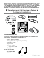

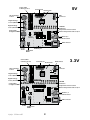
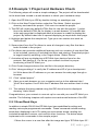


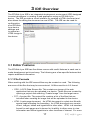
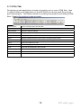
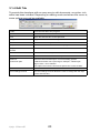
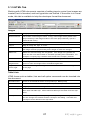
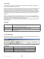

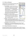


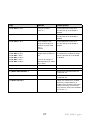

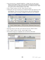

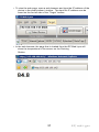
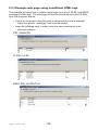
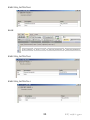
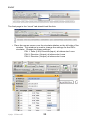


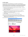


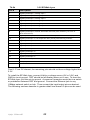
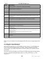
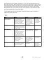


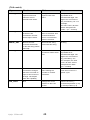
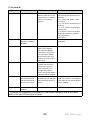
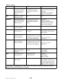
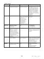
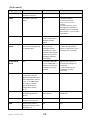
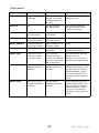
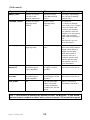
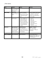
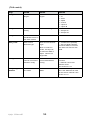


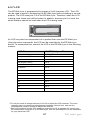


![[ActionX DVS5G9]を 豊富なオプションと](http://vs1.manualzilla.com/store/data/006551907_2-22955ea2d03d47ae9c24816caac3a79d-150x150.png)