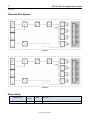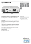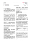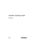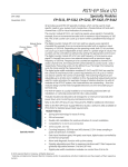
1
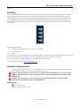
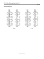
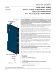
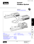
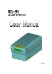
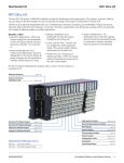
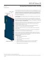
RSTI-EP Slice I/O Analog Output Modules EP-4164, EP-4264 GFK-2961 November 2015 Module Status LED Channel Status LEDs GE provides RSTi-EP analog output modules with up to 4 analog outputs at +/-10 V, +/-5 V, 0-10 V, 0-5 V, 2-10 V, 1-5 V, 0-20 mA or 4-20 mA. The resolution is 16 bit per channel. An output can be connected to each connector, the internal switching is carried out automatically. The output range is defined using parameterization. A status LED is assigned to each channel. The outputs are supplied with power from the output current path (IOUT). The EP-4264 module provides individual channel diagnosis with channel related error messages. Each module features a type plate, which includes identification information, the key technical specifications, and a block diagram. In addition, a QR code allows for direct online access to the associated documentation. The software for reading the QR code must support inverted QR codes. Markers are available as accessories for labelling equipment. Each I/O module can be labelled using the markers to ensure clear identification when replacing individual modules or electronic units. The RSTi-EP station is usually installed on a horizontally positioned DIN rail. Installation on vertically positioned DIN rails is also possible. The outputs as well as the sense-lines of the AO modules must not be used as power outputs. Modules should to be allowed to de-energize for a minimum 10 seconds after power down, prior to starting any maintenance activity. Refer to the RSTi-EP Slice I/O User Manual (GFK-2958) for additional information. Analog Output Module Refer to the RSTi-EP Power Supply Reference Guide, a software utility available on PME V9.00, for detailed power-feed requirements. Module Features Control up to four analog outputs Module diagnosis Spring style technology for ease of wiring DIN rail mounted Double-click installation for positive indication of correct installation Supports indirect firmware update through the network monitor Supports hot insertion and extraction © 2015 General Electric Company. All Rights Reserved. Indicates a trademark of General Electric Company and/or its subsidiaries. All other trademarks are the property of their respective owners. * 2 RSTi-EP Slice I/O Analog Output Module GFK-2961 Ordering Information Module Description EP-4164 Analog Output, 4 Channels Voltage/Current 16 Bits 2, 3, or 4-Wire EP-4264 Analog Output, 4 Channels Voltage/Current 16 Bits with Diagnostics 2, 3, or 4-Wire Specifications EP-4164 System Data Data Interface System bus transfer rate Potential isolation Outputs Number Output levels Response time Resolution Accuracy Temperature coefficient Max. error between Tmin and Tmax Monotony Crosstalk between the channels Repeat accuracy Output ripple Voltage load resistance Current load resistance Actuator connection Short-circuit-proof Module diagnosis Individual channel diagnosis Substitute value Can be used with EP-19xx module Supply Supply voltage Current consumption from system current path ISYS Current consumption from output current path IOUT EP-4264 Process, parameter, and diagnostic data depend on the network adapter used. RSTi-EP system bus 48 Mbps Channel/system bus = yes Channel/channel = no 4 1. Voltage (0 – 5 V, ±5 V, 0 – 10 V, ±10 V, 1 – 5 V, 2 – 10 V) 2. Current (0 – 20 mA, 4 – 20 mA) 1 ms for 4 channels 16 bits 0.1 % FSR max., 0.05 % FSR typ. 20 ppm voltage / 31 ppm current measurement / K ±220 ppm FSR Yes ±0.001 % FSR max. < ±1 mV eff. max. 0.001 % ≥ 1 kΩ (at > 50°C (122 °F) max ambient temperature, total sensor current of 10 mA per channel but 25 mA per module) ≤ 600 Ω including field cable resistance 2-wire (current and voltage; automatic detection), 4-wire (voltage) Yes Yes No Yes Yes Yes 20.4V – 28.8V 8 mA 85 mA For public disclosure RSTi-EP Slice I/O Analog Output Module 3 GFK-2961 General data Operating temperature Storage temperature Air humidity (operation/transport) Width -20°C to +60°C (-4 °F to +140 °F) -40°C to +85°C (-40 °F to +185 °F) 5% to 95%, noncondensing as per IEC 61131-2 11.5 mm (0.45 in) Depth 76 mm (2.99 in) 120 mm (4.72 in) Height Weight 83 g (2.93 oz) 98 g (3.47 oz) Current Demand for Analog Output Modules Product ISYS IIN EP-4164 8 mA -EP-4264 8 mA -ISYS Current consumption from the system current path IIN Power consumption from input current path Power consumption from output current path IOUT Current demand of the connected sensors IS Current demand of the connected actuators IL x Must be included when calculating the power supply IOUT 85 mA 85 mA IS --- LEDs LED EP-4164 EP-4264 Module Green: Communication over the system bus Status Red: Module System Fault or Diagnostic Fault Red: Channel 0 at voltage output: overload 1.1 short-circuit, at current output: shunt resistance too high or line break detected -1.2 -1.3 -1.4 2.1 2.2 2.3 2.4 3.1 3.2 3.3 3.4 4.1 4.2 4.3 4.4 Red: Channel 1 at voltage output: overload short-circuit, at current output: shunt resistance too high or line break detected ---Red: Channel 2 at voltage output: overload short-circuit, at current output: shunt resistance too high or line break detected ---Red: Channel 3 at voltage output: overload short-circuit, at current output: shunt resistance too high or line break detected ---- Green: Communication over the system bus Red: Module System Fault or Diagnostic Fault Red: Channel 0 at voltage output: overload short-circuit, at current output: shunt resistance too high or line break detected ---Red: Channel 1 at voltage output: overload short-circuit, at current output: shunt resistance too high or line break detected ---Red: Channel 2 at voltage output: overload short-circuit, at current output: shunt resistance too high or line break detected ---Red: Channel 3 at voltage output: overload short-circuit, at current output: shunt resistance too high or line break detected ---- For public disclosure IL --- 4 RSTi-EP Slice I/O Analog Output Module GFK-2961 Field Wiring The connection frame can take up to four connectors, and four wires can be connected to each connector. Those four connectors are shown in the following figure. The Spring style technology allows either finely stranded or solid wire conductors with crimped wire-end ferrules or ultrasonically welded wires, each with a maximum cross-section of 1.5 mm² (16 guage), to be inserted easily through the opening in the clamping terminal without having to use tools. To insert fine stranded wires without wire-end ferrules, the pusher must be pressed in with a screwdriver and released to latch the wire. Connector Block Connector Specifications: • conductor cross-section 0.14 to 1.5 mm² (26 – 16 guage) • max. ampacity: 10 A • 4-pole The modules do not have a fused sensor/activator power supply. All cables to the connected sensors/actuators must be fused corresponding to their conductor cross-sections (as per Standard DIN EN 60204-1, section 12). Refer to the RSTi-EP Slice I/O User Manual (GFK-2958) for additional information. For technical assistance, go to http://support.ge-ip.com. Installation in Hazardous Areas EQUIPMENT LABELED WITH REFERENCE TO CLASS I, GROUPS A, B, C & D, DIV. 2 HAZARDOUS AREAS IS SUITABLE FOR USE IN CLASS I, DIVISION 2, GROUPS A, B, C, D OR NON-HAZARDOUS AREAS ONLY WARNING - EXPLOSION HAZARD - SUBSTITUTION OF COMPONENTS MAY IMPAIR SUITABILITY FOR CLASS I, DIVISION 2; WARNING - EXPLOSION HAZARD - WHEN IN HAZARDOUS AREAS, TURN OFF POWER BEFORE REPLACING OR WIRING MODULES; AND WARNING - EXPLOSION HAZARD - DO NOT CONNECT OR DISCONNECT EQUIPMENT UNLESS POWER HAS BEEN SWITCHED OFF OR THE AREA IS KNOWN TO BE NONHAZARDOUS. ATEX Marking II 3 G Ex nA IIC T4 Gc Ta: -20°C to +60°C (-4° F to +140 °F) For public disclosure RSTi-EP Slice I/O Analog Output Module 5 GFK-2961 Connection Diagrams EP-4164 EP-4264 For public disclosure 6 RSTi-EP Slice I/O Analog Output Module GFK-2961 Connection Block Diagrams EP-4164 EP-4164 EP-4264 EP-4264 Release History Catalog Number EP-4164, EP-4264 Firmware Version Date 01.00 Nov-2015 Comments Initial Release For public disclosure RSTi-EP Slice I/O Analog Output Module 7 GFK-2961 Important Product Information for this Release Updates Initial Release Funcional Compatibility Initial Release Problems Resolved by this Release None – Initial Release New Features and Enhancements None – Initial Release Known Restrictions and Open Issues None Operational Notes None Product Documentation RSTi-EP Slice I/O Module User Manual (GFK-2958) RSTi-EP Slice I/O Functional Safety Module User Manual (GFK-2956) GE Intelligent Platforms 1-800-433-2682 1-434-978-5100 www.ge-ip.com For public disclosure