1
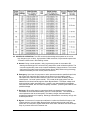
TECHNICAL SPECIFICATIONS for
Single Phase, (3 to 20 kVA) & (3 to 15 kW)
Battery Backup System
Crucial Power Products
Shadow
PTT6506B 3/10/08
1.0 GENERAL
1.1 SUMMARY: This specification defines a one-phase, on-line, solid-state, high frequency,
double conversion system, hereafter referred to as the ”Shadow”. It is designed to provide
high quality regulated and conditioned uninterruptible AC power to both linear and non-linear
loads during all modes of operation. The unit shall be specifically designed to meet UL 924A
for emergency lighting applications. It shall be suitable for all lighting loads including
Incandescent, Fluorescent, HID and HPS. It has an industry distinctive small footprint
stackable cabinet design allowing for equipment protection in limited spaces.
1.2 STANDARDS: The UPS shall comply with the following standards:
A - CSA certified per UL1778,
B - CSA 22.2
C - UL 924A – Fire and Life Safety for Emergency Back up Lighting
D - FCC rules and regulations, Part 15, subpart j, class A
E - The unit’s design shall comply with applicable sections of codes by NEC, NEMA, OSHA
1.3 SUBMITTALS
A. Proposal Submittals: submittals with the proposal shall include the following
documents: complete electrical characteristics, connection requirements, system
configuration on a single-line diagrams, description of equipment to be furnished, size
and weight of shipping units, detailed installation drawings showing cable entries and
the terminals locations.
B. Delivery Submittals: submittals on delivery shall include a complete set of submittal
drawings and one user’s manual with installation and maintenance guidelines. The
manual shall contain diagrams, safety precautions, illustrations, step-by-step operating
procedures, and routine troubleshooting information. Software packages, diagrams,
cables and user’s manuals shall be delivered for all optional accessories as required.
1.4 QUALIFICATIONS AND QUALITY ASSURANCE
A. Manufacturer’s Certification: A minimum of twenty years experience in the design,
manufacture and testing of solid-state UPS is required. The manufacturer shall
specialize in manufacturing of on-line, double conversion high frequency UPS modules
specified in this document. The manufacturer shall hold a current ISO 9001 certification
and shall design the units in accordance with internationally accepted standards.
Page 1 of 1
SHT6506C
B. Materials and Assemblies: All materials and parts in the UPS shall be new, of current
manufacture, unused, except for the purpose of factory testing. All active electronic
components shall be solid state and designed as to not exceed the manufacturer’s
recommended ratings and tolerances for ensuring maximum reliability. All IGBTs and
other semiconductor devices shall be sealed. All relays shall have dust covers. All
incoming parts, modular assemblies and sheet metal shall undergo detailed receiving
quality inspection.
C. Factory Testing: Every unit shipped will have completed a documented functional test of
the UPS module and battery system, including a battery discharge test. A copy of the test
report shall be available upon customer’s request.
1.5 ENVIRONMENTAL REQUIREMENTS
A. Temperature: operating - 0 C to 40 C (32 F to 104 F )
storage - 20 C to +45C (- 4F to 113 F)
B. Humidity: operating and storage: 0 to 95% RH, non condensing
C. Altitude: up to 6000 ft (1,829 meters)
D. Audible Noise: 57 dB on “response curve A”
1.6 WARRANTY
A. UPS Module: The UPS manufacturer shall warrant the UPS against defects in materials
and workmanship for a period of twenty-four (24) months. The warranty shall cover all
parts and labor for one (1) year period beginning from the start up, or 18 months from the
ship date, whichever comes first. Optional 1 year extended warranty and maintenance
contract packages shall also be available at the end of the factory maintenance period.
B. Battery: Battery manufacturer’s standard warranty shall be transferred and assigned to
the end user. It will have a minimum period of one year
2.0 PRODUCT DESCRIPTION
2.1 APPROVED MANUFACTURERS AND PRODUCT DESCRIPTION
A. Approved Manufacturer: The UPS shall be a Battery Backup System
and shall be manufactured by:
CRUCIAL POWER PRODUCTS
5701 Smithway Street
Commerce, CA 90040.
Phone: (323) 278-9550, Fax: (323) 278-9555
Power Wave Service – 1 800 797 7782
B. Product Description: this specification describes Shadow, single phase, on-line,
double conversion, high frequency UPS module. It is designed to provide high quality
regulated and conditioned uninterruptible AC power to both linear and non-linear loads
during all modes of operation. The system shall consist of a solid state, IGBT PWM
Page 2 of 2
SHT6506C
inverter, rectifier, static switch, internal maintenance bypass switch, battery, status and
metering display and communication ports as described herein.
1. Modular Design: The unit shall be specifically designed as a modular system to
minimize the number of replaceable assemblies. Except for the transformers,
contactor, circuit breakers, chokes and terminal blocks, the actual power conversion
and control system is limited to two replaceable parts: heat sink with IGBTs and
drivers, and control board with associated panel display. Both parts are easily
accessible and can be hot swapped in manual bypass mode. Modular design results
in a clear component layout for maximum EMI reduction and system reliability, due
to distributed heat rejection pattern.
2. Equipment Safety: The UPS shall have only front door access with a keyed door
lock provision to prevent system operation by unauthorized personnel. The controls
shall be accessible only from the inside of the cabinet, in compliance with UL 924A
safety standard. Operator activated CB’s shall be located at the front of the middle
shelf, for the ease and safety of operation. All remaining components shall be easily
accessible from the front, across the narrow, 18”- wide cabinet and located on a
multiple tiered shelves. This design provides a separation between the transformer,
breakers and power electronic sections and is safer for operation, maintenance and
troubleshooting.
3. Minimum Maintenance Time: The electronic modules shall be easily removable,
hot swappable (in manual maintenance bypass mode) with clearly marked, keyed
plug connectors. The UPS enclosure shall have vent louvers designed to prevent
dust collection inside the cabinet, eliminating the need for any filters to further
minimize required maintenance time
2.2
SYSTEM DESCRIPTION
A. UPS Design Requirements
1. Output Power Rating: The continuous output power rating of the UPS shall be
[
] kVA at 0.8 lagging power factor
2. Output Power Upgrade – unit shall be designed to have a min 20% of the rated power
capacity upgradeability without having to change the unit, option specified at the time of
ordering.
3. Input Voltage: [
] VAC, – 15% / + 10%
4. Output Voltage - [
] VAC, 1 phase, 2 wires plus-ground
5. Battery Autonomy: the UPS shall be capable of operating at full load for 5 to 31
minutes, depending on model, at 0.8 PF output on battery power, at 25 C temp.
6. Battery Type: valve regulated sealed lead-acid (VRLA), low maintenance
7. Battery Protection: battery CB, for safe UPS, battery operation and servicing
8. Cable Installation: conduit entries on the back and sides of enclosure
B. AC Input Specifications
1. Input Voltages: 120 / 208 / 240 / 277 VAC, 2 wires plus ground
2. Frequency: 60 Hz +/- 5%
3. Input Current: sinusoidal, 0.95 PF under all line/load conditions. Power factor
correction.
4. Input Protection: circuit breaker, contactor
5. Input Surge Protection: optional Transient Voltage Surge Suppressor (TVSS)
6. Transfer Time: zero
7. Input Power Connections: hard wired terminal block, optional input cable
Page 3 of 3
SHT6506C
8. Number of Wires: 2 wires plus ground
9. Cable Installation: conduit entries on the back and both sides of enclosure
C. AC Output Specifications
1. Output Ratings: 3 kVA / 2.1 kW, 5 kVA / 3.5 kW, 7.5 kVA / 5.25 kW, 10 kVA /
7.0 kW, 12.5 kVA / 8.75 kW, 15 kVA / 10.5 kW, 20 kVA / 14 kW
2. Output Voltages: 120 / 208 / 240 / 277 VAC
3. Frequency: 60 Hz +/- 0.5 Hz (when on inverter)
4. Voltage Regulation: +/- 3% No Load to Full Load, High Line to Low Line
5. Output Waveform: sinusoidal
6. Voltage Distortion: < 5% THD; < 3% Single Harmonic
7. Power Factor: 0.8 at the rated volt-amperes (kVA)
8. Inverter Overload Capability: 125% for 10 minutes, 150% surge for 10 seconds
9. Bypass Overload Capability: 150%
10. Protection: fault current limited
11. Non-Linear Load Capability: 100%
12. Slew Rate: 2 Hz/second, maximum
13. Crest Factor: 1 to 2
14. Output Power Connections: hard wired terminal block, optional output receptacle
panel board with NEMA type receptacles and overcurrent protection (max 30 CBs)
15. Output Distribution: unit shall have an internal or external load center for
customer use, eliminating the need for optional distribution
16. Number of Wires: 2 wires plus ground
D.
Battery Specifications
1.
2.
3.
4.
5.
6.
7.
8.
Standard Run Time: 5 – 45 min. at full load, depending on model
Extended Run Time : as required
Battery Type: sealed, maintenance-free, lead-acid, VRLA
Expected Life: 10 years
Charger Ampacity: per UL 924
Float Voltage: 2.25 V per cell
Protection: circuit breaker in each battery cabinet
Wiring: power cables from the UPS to the battery cabinet shall be provided by the
customer, per local code. With multiple battery cabinets, interconnecting cables
shall be provided.
9. Nominal DC Link Voltage: kVA/kW, ( dependent on number of batteries )
a) 3 kVA / 2.1 kW
- 96 VDC
b) 5 kVA / 3.5 kW
- 120 VDC
c) 7.5 kVA / 5.25 kW - 120 VDC
d) 10.0 kVA / 7.0 kW - 192 VDC
e) 12.5 kVA / 10.5 kW - 192 VDC
f) 15.0 kVA / 10.5 kW - 240 VDC
g) 20.0 kVA / 14.0 kW - 240 VDC
10. Battery Cabinets: matching battery cabinets, UL 924A listed, NEMA 1, consult
factory for other types. The specific UPS and batter cabinet shall be a CSA listed
system per UL924A,
F.
Physical Specifications
Page 4 of 4
SHT6506C
2.3 MODES OF OPERATION: The UPS module shall be designed to operate as an on-line,
high frequency (min 10 kHz), high precision PWM conversion, fully automatic system with
“no break” transfer time in the following modes:
A. Normal: During normal operation, utility (or generator) power is converted to DC,
drawing sinusoidal input AC current at unity power factor under all load conditions. The
converter supplies DC power to the Inverter and Battery Charger sections. The Inverter
shall supply the load through the Static Bypass Switch (SBS) without using the energy
stored in the battery at a min.10 kHz power conversion.
B. Emergency: Upon loss of input power or when power exceeds the specified input limits,
the control logic shall allow the inverter to draw energy from the battery without
interruption to the load and disconnect the input line. The transfer to battery shall be
uninterrupted - "no break" power transfer. The inverter shall supply power from the
batteries to the critical load through the Static Bypass Switch. The output voltage shall
be sinusoidal and within specified limits. If power is not restored before the batteries
have been exhausted, the UPS shall completely shutdown - protecting the batteries from
possible damage.
C. Recharge: When utility power is restored and before the batteries are completely
exhausted, the UPS shall automatically return to normal operation. This retransfer to
normal operation shall be uninterrupted. The battery charger shall automatically
recharge the batteries to full capacity. Recharge characteristics must strictly comply with
UL924 requirements.
D. Bypass: In the event of a component malfunction in either the Rectifier/Charger or the
Inverter sections, the unit’s Static Bypass Switch shall transfer the load to the utility
power with no interruption. Bypass mode shall cause alarm indication and initiate output
relay dry contacts closure for customer use.
Page 5 of 5
SHT6506C
E. Off-Battery: When the battery is removed for maintenance or the battery breaker is off,
the unit will continue to function, meeting all the specified performance parameters with
the exception of the power back up time capability.
2.4 COMPONENT DESCRIPTION
A. Input Terminal Block: an input terminal block shall be hard wired, and located in the
UPS close to knockouts for incoming power cable for easy installation. The conduit
entries shall be located on the top and both sides of the cabinet.
B. Optional Input Circuit Breaker: a circuit breaker shall be provided and hard wired at
the UPS input for protection from the utility line and associated wiring disturbances. An
optional, higher KAIC breaker shall be available, and should be specified when required.
C Input Contactor: The UPS shall have a line contactor to isolate the rectifier in case of a
line problem and allow for a smooth transfer/retransfer to and from bypass.
D. Input Transformer: An input transformer shall be factory installed inside the standard
UPS cabinet within 39” x 18” footprint design. It shall be located in the lower part of the
cabinet, with a barrier separating from the electronics section, to provide isolation
between the line and the rectifier / inverter circuit.
E. Rectifier: a solid state circuit design, converting incoming AC power to regulated DC
bus voltage for the input to the inverter and battery charger.
F. Inverter: The inverter shall feature pulse-width modulation (PWM) design utilizing high
frequency (15 kHz) switched IGBT’s. It shall use a true double conversion system,
generating rated AC output from the utility power, or the batteries when in back up mode.
The unit shall have a single heat sink and power IGBT’s assembly tray for reduced
switching noise and maximum reliability. The assembly shall come as a FRU and its
design and mounting location shall be conceived for an easy maintenance. It shall be
located on the electronics shelf with direct access, with opened door and can be replaced
in app.15 min, using only a screwdriver.
G. Charger: A separate battery charger circuit shall be provided. It uses the same IGBT’s
as in the inverter, with constant voltage and current limiting control. The battery float
voltage is uP programmable for the applicable kVA and DC bus ratings. Charging
current limit is temperature compensated for battery protection. Full recharge of the
batteries shall be in full accordance with UL 924. The rectifier, inverter and charger shall
be a part of the heat sink, IGBTs and drivers subassembly as part of FRU modular
design aimed at increased ease and safety of service.
H. Static Bypass : 100% rated, Continuous Duty
The bypass serves as an alternative source of power for the critical load when an input
line failure or abnormal condition prevents operation in inverter mode. It consists of a fully
rated, continuous duty static switch for high-speed transfers and features two back to
back SCRs to allow make before break transfer. The design shall include a Manual
Bypass Switch, protected within the locked cabinet. It shall be accessible only to
authorized personnel, allowing the unit to stay in bypass at all times for safe work on the
unit. Manual transfer to bypass shall not cause unit trip, nor transfer into battery back up
mode. The static switch shall be able to be powered up by an optional separate power
source (generator or other power supply) for dual input capabilities.
1. Transfer to Bypass - will initiate automatically under the following conditions:
Page 6 of 6
SHT6506C
a) Critical bus voltage out of limits
b) Total battery discharge – ( for specified back up time w/o damaging batteries)
c) Over temperature period expired
d) UPS problem
2. Automatic Re-transfer - takes place whenever the inverter is capable of assuming
the critical load. It shall be inhibited for the following conditions:
a) When transfer to bypass is activated manually or remotely
b) UPS problem
3. All Transfers to Bypass shall be inhibited for the following conditions
a) Bypass voltage out of limits (+/- 10 % of nominal)
b) Bypass frequency out of limits (+/- 3 Hz)
I. Control Logic: The entire UPS operation shall be performed by the microprocessor
controlled logic. All operations, parameters, diagnostics, test and protection routines are
firmware controlled, compensating component drift and changes in operating
environment to ensure stable and consistent performance. A self-test and diagnostics
subroutine shall assist in troubleshooting the unit. Control PCB shall be located on the
front door, removed from power wiring and switching devices. This arrangement shall
minimize EMI and allow hot boards swap, in manual bypass mode.
J. Manual Maintenance Bypass Switch: An auto/man MBS switch shall be provided in the
UPS cabinet for connecting power to the critical load through the external maintenance
bypass line. It shall be used when the unit needs to be de-energized for maintenance,
without disrupting power to the load. Operating the switch shall be strictly restricted to
authorized personnel with cabinet access key. The MBS shall be operated in conjunction
with a S-1 synchronization switch, ensuring full synchronization and no inrush current
during transfer.
K. Output Transformer: An isolation output transformer shall be utilized to provide
specified output voltage and separate the UPS rectifier/Inverter section from the load
disturbances and conducted noise.
L. Manual Inverter Test Switch: Unit shall have a momentary test switch to allow the user
a manual system test without the need to operate any breakers or shutting down the
system. The test switch shall be in compliance with UL924A rules, well marked,
accessible only after opening a locked front cabinet door and further protected from
accidental activation. The Power Wave shall resume a normal operation after the test
switch release.
M. Battery Subsystem: Sealed, maintenance-free VRLA batteries shall be provided. The
batteries shall have an expected life of 10 years or a minimum 250 complete discharge
cycles. The batteries shall be contained in a separate battery cabinet with a dedicated
circuit breaker (no fuses) for battery protection, convenient power cut-off, and servicing.
Battery run time (based on 100% full load) shall be no less than the specified time.
Runtime shall comply with UL924A providing a specified back up time at full load.
3.0 SYSTEM INDICATORS AND MONITORING
3.1
Front Panel LCD Display: Standard, 4 lines x 20 characters back lit, blue LCD display on
the UPS for instant indication of UPS status, metering, alarms and battery condition. The
Page 7 of 7
SHT6506C
display provides easy read-out on 2 standard and 2 optional screens, providing continuous
information with scrolling update:
A. Status Screen
1) Start Up : first screen to appear after energizing the unit
2) Stand By: unit continues internal check and self test
3) Normal : normal operating status, on inverter
4) UPS : kVA - indicates unit’s nominal capacity in kVA
5) Input : OK input power available;
6) Input BAD - no input power or out of limits
7) Charger: On - charger operational;
8) Charger: Off no input power
9) Battery: OK battery charged;
10) Battery: Bad - battery not charged
11) DC: OK – DC bus voltage normal;
12) UV: bus undervoltage;
13) OV: bus overvoltage
14) On Inverter: load supplied from inverter,
15) Out OK: output OK,
16) Out Bad: no output
10) On Battery: unit supplies load from battery power
11) On Bypass: unit supplies load via bypass
12) PM REQ:elapsed maintenance interval reminder
B. Metering Screen
1) Output: UPS output voltage
2) Output Power: total actual power - W
3) Input Voltage: UPS input voltage
4) Input Current: total input current
5) DC Bus: actual DC bus voltage, VDC
6) DC Bus: current in A (factory use)
7) Batt: -actual battery voltage, VDC
8) Batt: Charging (+), discharging(-) current
C.
D.
Events and Alarms screen - Optional
1) UPS Events Time/Date stamp up to 50 scrolling events, with freeze function
st
2) Aux. Output CB Trip – up to 20 CBs Trip alarm on 1 priority trip screens,
System Information Screen - Optional
1) Minutes on Battery: UPS in battery back up mode, accrued time
2) System Hours: UPS in operation, accrued time
3) Battery Event: number of times UPS operated in back up mode
4) Temp: UPS cabinet temperature
3.2 Alarm Relays: Standard, dry contacts signal relays closing for each of the following alarm
conditions: Input Fail, On Bypass, Low Battery, Summary Alarm
3.3 Communication Ports: Standard, Three com ports are available, 2 configured for RS232
type protocol and 1 for RS485 data transfer. All parameters displayed on front panel shall be
available on these ports for remote monitoring
Page 8 of 8
SHT6506C
3.4 Power Flow Mimic: Optional. A laminated overlay with embedded color LED’s. Combines
information on front panel display with a graphic power flow visualization for instant load
power status recognition
3.5 Optional Global Monitoring System (GMS): All GMS items are optional. The GMS shall
allow for flexibility in local and remote communications including internet access
A.
Local On UPS Display
1. Event Log: Monitoring uP circuit acquires system data and displays up to 50
most recent Date/Time stamped events on the front panel display. Its keyselectable menu provides access to events, system information, display, freeze
and delete functions.
2. Aux. CBs Trip Monitor with Event Log: In addition to the event log and
system data, this option registers trips of up to 20 auxiliary output circuit breakers
for monitoring of dedicated circuits.Trip signals from the breakers are displayed on
a CB trip screen. Trip modules mount easily on a DIN rail with aux.CB’s.
B. Local On PC - Via RS232 or RS485 Port: This option requires a PC and LabView
monitoring software on a Windows platform. Data sent to PC’s is displayed as a
control room panel for real-time monitoring. The distance to PC for RS232 cable
shall be 25 – 150 ft, RS485 increases the range to 1000 ft
C. Remote Dial Up- Monitor 2000: The Monitor 2000 requires a phone line for
remote operation. The device shall send data, voice and text messages to 32
destinations like phone, fax, pager and e-mail via phone line DSL service. The
Manager 2000 Windows software installed on a remote PC displays UPS
parameters, events and stats graphs. The device shall be installed in the unit and
comes fully wired and function-tested
D. Web/SNMP Card: This option is a web enabled monitoring device for a unit with
Internet or network connection. The internal IP internet address, can be preinstalled in firmware to fit customer network settings. The SNMP/Web card can
monitor the UPS on the network through a standard web browser. A Network
Management System software with Alarm Viewer utility shall provide monitoring of
multiple units on a single console application.
4.0 MECHANICAL DESIGN AND CONSTRUCTION
4.1 Enclosure: All system components shall be housed in a single floor mounted small
footprint (18” x 32 or 18” x 39”), freestanding NEMA 1 enclosure. The cabinet should have
front access only with two doors and the depth of no more than 18 inch, allowing easy
component reach from the front. The enclosure shall have shelves for component separation
and clear and accessible layout. Cabinet doors shall require a key for gaining access. Front
access only shall be required for safety and expedient servicing, adjustments and
installation. The cabinets shall be structurally adequate and have provisions for hoisting,
jacking and forklift handling. Enclosure design shall fully comply with UL 1778 for locked
door, unauthorized access protection and UL 924A for accidental or unauthorized unit
shutdown.
4.2 Construction: Only quality, unused material shall be used to build the unit, under strict
observance of standards and quality workmanship. The cabinets shall be cleaned, primed
and painted matt black. The unit shall be constructed with rigorously tested, burned-in,
replaceable subassemblies. Only two electronic subassemblies: heat sink assembly with
IGBTs and drivers and control PCBA shall be used for maximum reliability and simple
Page 9 of 9
SHT6506C
servicing. All printed circuit assemblies shall have plug connections. Like assemblies and
like components shall be interchangeable.
4.3 Earthquake Protection: The cabinet shall be evaluated for earthquake zone 4 installation,
with the addition of optional earthquake brackets.
4.4 Wiring Installation: UPS cabinet conduit entry arrangement shall allow for flexibility of user
wiring installation. The wiring shall be routed thru the top or either side of the cabinet.
4.5 Wiring Termination: The UPS input and output power connections shall be hard wired
within the cabinet. Optional input line cable and output receptacle panels shall be available
(limited range of units only, please consult factory for details). Input and output terminal
blocks shall be provided for easy field wiring of UPS and battery cabinets
5.0
ACCESSORIES (OPTIONAL COMPONENTS)
5.1 External Manual Bypass Switch: If specified by the customer, The bypass switch,
enclosed in a box, could be field mounted in the UPS cabinet or an adjacent wall. This box
includes a rotary switch with make before break contacts to provide a single control for
transferring to and from maintenance bypass with no load support interruption.
5.2 Audio Alarm with Silence Switch: Provides audible warning signal, acknowledge and
reset for Input Fail, On Bypass, Inverter On, Low Battery and Summary Alarm for any of the
foregoing alarm conditions.
5.3 Remote UPS Status Panel: The Remote Status Panel is available in a console mount style
box in black finish. It can also be wall mounted and comes with a 10 ft long “DB” connector
signal cable or optional cable that can be up to 1000 feet long. Remote Status Panel
requires 120 VAC power, comes with 6 ft power cord, Silence, LED /Horn test switches. It
includes following LED’s: Input Fail, On Bypass, Inverter On, Low Battery, Summary Alarm.
5.4 Form “C” Relay Contacts: Terminal strip TB is provided on the optional alarm relay board
for user connection to the individual alarm contacts. The Remote Contact Board includes
isolated Form C contacts for the same signals as on the Remote UPS Status Panel.
5.5 Transient Voltage Surge Suppressor (TVSS): TVSS is a DIN rail mounted device,
connected to the UPS input. Its plug-in phase modules are easily replaceable. The device
contains energy absorbing components and has a two-stage protection. When a protection
component is damaged by absorbed transient, the module will display a flag indicating a
need for replacement. At this time the device is still operational, due to redundant circuits.
After the second spike, the device shows alarm condition indicating need for replacement.
Remote indication contacts “TS” allows remote control of the protection status.
5.6 External Status Indicator: customer use, N/O volt-free contacts compatible with IBM
AS400 standard shall be provided on a plug-in standard connector for the following signals:
Low Battery, On Bypass, Summary Alarm and Input Fail
5.7 Normally On/ Normally Off Output Aux. Circuit Breakers: These CB’s are 1 pole, 20 A
devices for protection of customer’s load circuits. Combine 5.7 & 5.8 to eliminate the need
of internal output breakers
Page 10 of 10
SHT6506C
5.8 External Output Aux. CB’s In Panel Board: 1 pole, 20 A located in external panel board
mounted on the UPS cabinet side. Maximum number of QO breakers – 42
5.9 EMI Filter: complies with: EN55022, 1998 Class ”B” Radiated Emission EN55022, 1998
Class “B” conducted emission. FCC Part 15 Class “B” radiated emission, FCC Part 15 Class
“B” conducted emission.
5.10 Higher KAIC Norm On/Off Output CB: 1 Pole, 20 A Circuit Breaker with Higher KAIC, DIN
rail mounted or molded case design.
5.11 Seismic Mounting Brackets: Left / Right seismic floor mounting brackets
5.12 Battery Monitoring System: single jar, string and entire system monitoring on a local,
remote or web enabled PC. Assessment of actual remaining charge and jars deterioration
for maximum battery life and total back up safety.
6.0 SERVICE
6.1
Service Personnel: The UPS manufacturer shall employ a nationwide service organization,
with factory-trained Customer Service Engineers dedicated to the start-up, maintenance,
and repair of UPS and power equipment. The manufacturer shall provide a fully automated
national dispatch center to coordinate field service personnel schedules. One toll-free
number shall reach a qualified support person 24hrs/day, 7days/week and 365 days/year.
For emergency service calls, response time from a local Customer Engineer shall be
approximately 15 minutes.
6.2
Replacement Parts: Parts shall be available through an extensive network to ensure
around- the-clock parts availability throughout the country. Customer Support Parts
Coordinators shall be on-call 24hrs/day, 7days/week, 365 days a year for immediate parts
dispatch. Parts shall be delivered to the site within 24 hours.
6.3
Maintenance Training: In addition to the basic operator training conducted as a part of the
system start-up, class-room courses for customer employees shall be made available by the
manufacturer. The course shall cover UPS theory, location of subassemblies, safety, battery
considerations and UPS operational procedures. It shall include AC/DC and DC/AC
conversion techniques as well as control and metering, Troubleshooting and fault isolation
using alarm information and internal self-diagnostics interpretation shall be stressed.
6.4 Maintenance Contracts: A comprehensive offering of preventive and full service
maintenance contracts shall be available. An extended warranty and preventive
maintenance package shall be available. All services shall be performed by factory trained
Service Engineers.
6.5 Site Testing: The manufacturer’s field service personnel shall provide site testing if
requested. The testing shall consist of a complete test of the UPS system and the
associated accessories supplied by the manufacturer. A partial battery discharge test shall
be provided as part of the standard start-up procedure. The test results shall be
documented, signed, and dated for future reference.
NOTE: This Guide Specification follows the Construction Specification Institute guidelines per CSI
MP-2-1,MP-2-2. It is subject to change due to product improvement and/or enhancement.
Please use this document as a guide specification, and do not hesistate to contact our application
engineering department, should you have any further questions or special requirements.
Page 11 of 11
SHT6506C
You can contact us at: 800 –227-8899, or via e-mail: [email protected],
[email protected]
Dec. 2006
Page 12 of 12
SHT6506C