1
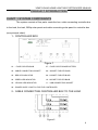
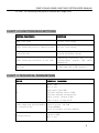
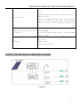
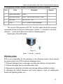
30WP SOLAR HOME LIGHTING SYSTEM USER MANUAL
Thanks for choosing 30Wp solar home lighting system
Please refer to the manual before using
MODEL: 30W SOLAR HOME LIGHTING SYSTEM
Model No:SHS-30
Standards:Q/ZX 01024-2010
Q/ZX 00966-2012
Q/ZX 01069-2011
IEC60896-21/22
GB/T 9535-2006
GB 19064-2003
GB/T 2828.1
GB/T 2829
ZTE MAKES THE WORLD WARMER
ZTEMAKES THE WORLD BRIGHTER
1
30WP SOLAR HOME LIGHTING SYSTEM USER MANUAL
CONTENT
BRIEF DESCRIPTION
2
LIST OF MAIN EQUIPMENT
3
PRODUCTS INRODUCTION
4
CHAPT1 SYSTEM COMPO NENTS
4
CHAPT2 FUNCTIO N DES CRIPTIONS
6
CHA P T3 TE CHNI CA L PA RA METE RS
6
CHAPT 4 ELECTRICAL PRINCIPLE CHART
07
I N S TA L L AT I O N I N T R O D U C T I O N
8
D I S P L AY S TAT U S
112
NORMAL FAULTS RECOVER
12
MAINTENANCE
113
WARRANTY NOTES
13
1
3
Brief Description:
SHS-30 is designed and produced for home users. It is a solar power system which
has advantages of portability, safety, long life and low maintenance cost. SHS-30 is made
up of solar module, bracket and support, battery, controller box, cables, 3pcs of 3W LED
lamp and other accessories. The solar module converts sunlight directly into electricity. It
charges the battery by the charge controller and then the electricity is stored in the battery.
The DC loads get the electricity power from the controller box.
2
30WP SOLAR HOME LIGHTING SYSTEM USER MANUAL
LIST OF MAIN EQUIPMENT
ITEM
PARTS DISCRIPTION
UNIT
QTY
REMARK
1
30Wp solar panel
pcs
1
polycrystalline solar modules
kit
1
2
supporting frame
for solar
panel
25°-35°adjustable, 5°per step, with screw &
mounting bolt
3
Controller
4
3W LED lamp
5
cable(for connecting solar
box (12V 10A)
kit
1
pcs
3
kit
1
length 9.2m per kit
kit
3
length 9.2m per kit
12V/28AHbattery & main control board built in
panel to controller box)
6
cable(for connecting control
box to load)
expansion bolt m6 6kit
7
spare package
box
1
hexagonal bolt m6 4 kit
fuse 4 kit
stepping 4 pcs
8
Compass
pcs
1
solar panel mounting direction locating
9
user manual
pcs
1
version of Urdu, English, Chinese
3
30WP SOLAR HOME LIGHTING SYSTEM USER MANUAL
PRODUCT INTRODUCTION
CHAPT 1 SYSTEM COMPONENTS
The system consists of five parts: controller box, cable connecting controller box
to the load, the load, 30Wp solar panel and cable connecting solar panel to controller box
(see principle chart).
1、CONTROLLER BOX
Figure 1
01— FUSE FOR LED BULB
07—FUSE FOR STORAGE BATTERY
02—CABLE CONNECTING SOCKET
08—SOCKET FOR LED BULB
03—RED LED INDICATOR
09—SOCKET FOR LED BULB
04—GREEN LED INDICATOR
10—SOCKET FOR LED BULB
05—YELLOW LED INDICATOR
11—USB CONNECTING SOCKET
06—POWER SUPPLY SWITCH FOR THE CONTROLLER
2、CABLE CONNECTING CONTROLLER BOX TO THE LOAD
Figure 2
4
30WP SOLAR HOME LIGHTING SYSTEM USER MANUAL
12—CABLE CONNECTING CONTROLLER BOX TO LED LAMP
13—CABLE CONNECTING CONTROLLER BOX TO LED LAMP
14—CABLE CONNECTING CONTROLLER BOX TO LED LAMP
15—USB CONNECTING CABLES(PREPARED BY CUSTOMER)
3、THE LOAD
Figure 3
16—LED LAMP
18—LED LAMP
17—LED LAMP
19—LOAD FOR USB CONNECTING
4、30WP SOLAR PANEL
Figure 4
20—30WP SOLAR PANEL
24—BOX OF WIRING TERMINAL
21—SUPPORTING FRAME B
25—CABLE CONNECTING SOLAR PANEL TO CONTROLLER BOX
22—SUPPORTING FRAME A
26—MOUNTING BOLT FOR SOLAR PANEL TO FRAME A & B
23—WIRING TERMINAL“﹢”,“﹣” 27—EXPASION BOLT FOR FRAME A&B TO GROUND
5、CABLE CONNECTING SOLAR PANEL TO CONTROLLER BOX
5
30WP SOLAR HOME LIGHTING SYSTEM USER MANUAL
2*1.5mm², for connecting solar panel to controller box, length 9.2m ;
CHAPT 2 FUNCTION DESCRIPTIONS
SYSTEM COMPONENTS
FUNCTION
30Wp solar panel
collect solar energy
cable connecting solar to controller box
deliver solar energy
controller box
store & distribute energy
cable connecting controller to the load
connecting controller box to the
load(customers prepare USB cables
themselves)
the load
3 LED lamps and 1 USB interface
CHAPT 3 TECHNICAL PARAMETERS
DEVICE
TECHNICAL PARAMETERS
PV
model: 30W
Qty: 1 pcs
peak power value:30W
the best working curret:1.83A;
the best working voltage:16.4V
short circuit current:1.98A
open circuit voltage:21.6V
cable connecting solar PV module
to controller box
storage battery
specifications: 2*1.5mm²;
length=9200mm;
Qty:1 kit(socket, wiring terminal)
capacity:28Ah
Qty: 1 pcs
6
30WP SOLAR HOME LIGHTING SYSTEM USER MANUAL
controller box
Qty:1
Interface: PV input interface:1; lamp interface:3;
USB interface:1
indicator lamp:3 working status indicator lamps
switch: switch for control supply with indicator
fuse:2 ( battery fuse and LED power supply fuse)
cable connecting controller box
to the load
specification: 2*1.0mm²
length=9200mm
Qty:3kit(including lamp holder , plug and push
button switch
LED lamp
Qty:3 pcs
shape: conic
color: neutral white
CHAPT 4 ELECTRICAL PRINCIPLE CHART
Figure 5
7
30WP SOLAR HOME LIGHTING SYSTEM USER MANUAL
Figure 6
INSTALLATION INTRODUCTION
Installing tools:
1 M4 flat head screwdriver, 1 M4 cross screwdriver, 1 M6 socket wrench,
1 electric drill (with 8mm bit), and 1 mark pen (tools prepared by user).
Installation equipment, materials and accessories:
Support frame A, 2pcs, specification: 90mm*50mm*3mm
Support frame B, 2pcs, specification: 205mm*50mm*3mm(the angle is
adjustable to 25°, 30°, 35°)
Hexagonal screws, 4 kits, specification: M6*15 mm (with nut, plain washer
and spring washer)
Expansion bolt, 6 kits, specification: M6*50mm
Cable connecting solar panel to controller box, 1 kit, specification:
8
30WP SOLAR HOME LIGHTING SYSTEM USER MANUAL
2*1.5mm², L=9200mm
30Wp solar panel
Step 1: Confirm the installation location with compass.
Step 2: The installation angle of solar panel to ground is based on the
local sunshine parameters (25°/30°/35°optional). Choose the best angle.
Figure 7
Step 3: Fix the support frame A & B to the solar panel with hexagonal bolt.
Figure 8
Step 4: Put the support frame A & B to the installation location, mark the
installation hole with a pen.
9
30WP SOLAR HOME LIGHTING SYSTEM USER MANUAL
Figure 9
Step 5: Check the holes position and size given by installation guide map.
After confirmation, dig 6 holes at the identified location with an electric drill,
clean dust in the hole, install 6 expansion bolts, fix the bolts in place with a M6
socket wrench, and then remove the nut, plain washer and spring washer off
the bolts.
Figure 10
Step 6: Fix the support frame A&B to the expansion bolts on the ground
with a socket wrench, install the solar panel.
Step 7: Install the cable connecting solar panel to the controller box. Open
the cover of the terminal box, connect the anode(red wire) of cable to (“﹢”)
and cathode(black wire) to (“﹣”), then cover the terminal box tightly.
10
30WP SOLAR HOME LIGHTING SYSTEM USER MANUAL
Figure 11
Step 8: Controller box should be put in the room where is well drafty and
dry. Please don’t put anything on controller box. Connect cables according to
the installation diagram. At first, the battery fuse and DC out fuse should be
installed. After confirmation of correct connection, turn on the power supply
switch for the controller
, the green indicator
lights on means the
system is in normal condition, and the illuminating function can be used
normally. While the system is running do not turn off the power supply switch
for the controller to control the lamps or the solar system will not supply power
normally. In case of thunderstorm weather, please remove the cable
connecting solar panel from the controller box in order to avoid safety risk.
Figure 12
Green indicator lamp
Power supply switch for the controller (used as RESET when abnormal)
11
30WP SOLAR HOME LIGHTING SYSTEM USER MANUAL
DISPLAY STATUS
Indicator lamp(red,
yellow) board
green
and
1-Red
Single
lamp
2-Green
3-Yellow
Combinati
on lamps
Indication
Status
Lighting
Flash
Lighting
Low battery charge
Power down
Normal
Flash
Waiting for recovery
Lighting
Flash
Full charge
Overvoltage protection
Red+Green
Double Flash
Over discharge/Power down
Green+Yellow
Double Flash
Overcharge
Red+Green+Yellow
Three slow Flash
Over temperature
Red+Green+Yellow
Three slow Flash
Short circuit/Overload
Normal Faults Recovery
Item
1
2
Faults
No
illumination
No power
Solution
1, Wait 1 hour late auto-recover
2, Operating the main switcher (6) off/on
3, Check the fuse(10)
4, Watch the indicator and judge the station
5, Check the fuse (11) if necessary.
1,Check the main switcher whether it is on or turn it
off/on
2, Check all of the connection cables
3 Check the output ( DC12V ) of solar panel with
multimeter
4 Check life time of the battery
Remark
Please
contact the
vendor if the
faults is from
the parts
If abnormal condition happened (such as short circuit, the LED bulbs of
load part are not luminous), the system will recover again 1hour later.
If immediate recovery is necessary, please press RESET twice.
MAINTENANCE
Maintenance is unnecessary during guarantee period. If accessories need
12
30WP SOLAR HOME LIGHTING SYSTEM USER MANUAL
to be replaced, please consider the parameters listed as following:
Item
Parts
Parameter
1
30Wp solar panel
30WP
2
Lead-acid battery
28Ah,Size 223mm*81mm*175mm
3
LED bulb
3W, DC12V,E27
4
Fuse
10A(4 fuses in spare package)
Remark
The circuit of this product is DC12V, thus the cable should be correctly
connected during running or maintenance. (anode “+” connects to red wire, ,
cathode “-” connects to black wire (refer to following figure).
Electrodes of the LED bulbs
Figure 13
Notes: “+” anode; “-” cathode
Warranty notes:
ZTE is not responsible for the warranty in the following cases. Users should
buy spare parts from ZTE to replace damaged ones.
1. Physical damages due to improper use after the delivery of the product.
2. Product damages due to controller water inlet.
3. Damages by using the controller and storage battery installed outdoor.
4. Damages by natural disasters and force majeure (such as earthquake,
floods and lightning strike, etc.).
13