1
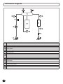
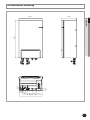
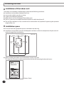
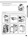
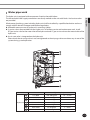
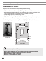
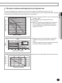
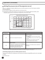
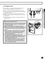
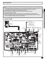
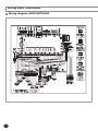
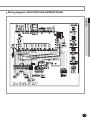
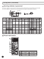
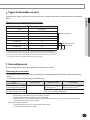
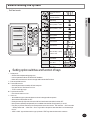
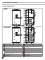
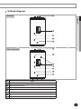
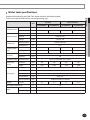
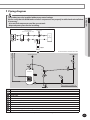
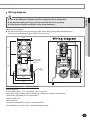
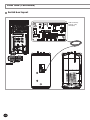
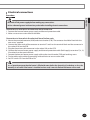
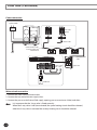
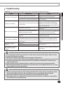
Contents E-2 Safety precautions . . . . . . . . . . . . . . . . . . . . . . . . . . . . . . . . . . . . . . . . . . . . . . . . . . . . . . . . . . . . . . . . . . Product specifications . . . . . . . . . . . . . . . . . . . . . . . . . . . . . . . . . . . . . . . . . . . . . . . . . . . . . . . . . . . . . . Typical application examples . . . . . . . . . . . . . . . . . . . . . . . . . . . . . . . . . . . . . . . . . . . . . . . . . . . . . . . . Main components . . . . . . . . . . . . . . . . . . . . . . . . . . . . . . . . . . . . . . . . . . . . . . . . . . . . . . . . . . . . . . . . . . Functional diagram . . . . . . . . . . . . . . . . . . . . . . . . . . . . . . . . . . . . . . . . . . . . . . . . . . . . . . . . . . . . . . . . . Dimensional drawing . . . . . . . . . . . . . . . . . . . . . . . . . . . . . . . . . . . . . . . . . . . . . . . . . . . . . . . . . . . . . . . Installing the unit . . . . . . . . . . . . . . . . . . . . . . . . . . . . . . . . . . . . . . . . . . . . . . . . . . . . . . . . . . . . . . . . . . . Pipe work . . . . . . . . . . . . . . . . . . . . . . . . . . . . . . . . . . . . . . . . . . . . . . . . . . . . . . . . . . . . . . . . . . . . . . . . . . . Wiring work . . . . . . . . . . . . . . . . . . . . . . . . . . . . . . . . . . . . . . . . . . . . . . . . . . . . . . . . . . . . . . . . . . . . . . . . Before running the system . . . . . . . . . . . . . . . . . . . . . . . . . . . . . . . . . . . . . . . . . . . . . . . . . . . . . . . . . . Troubleshooting . . . . . . . . . . . . . . . . . . . . . . . . . . . . . . . . . . . . . . . . . . . . . . . . . . . . . . . . . . . . . . . . . . . . DHW tank . . . . . . . . . . . . . . . . . . . . . . . . . . . . . . . . . . . . . . . . . . . . . . . . . . . . . . . . . . . . . . . . . . . . . . . . . . 3 5 8 10 11 12 13 15 22 31 32 35 Safety precautions All materials supplied to this manual are indispensable for the safety of equipment. Users shall establish appropriate safety and health practices and determine the applicability of regulatory limitation based on following descriptions prior to use. •A lways disconnect the air to water heat pump from the power supply before servicing it or accessing its internal components. • Verify that installation and testing operations are performed by qualified personnel. • Verify that the air to water heat pump is not installed in an easily accessible area. ENGLISH WARNING General information Carefully read the content of this manual before installing the air to water heat pump and store the manual in a safe place in order to be able to use it as reference after installation. For maximum safety, installers shall always carefully read the following warnings. Store the user and installation manual in a safe location and remember to hand it over to the new owner if the air to water heat pump is sold or transferred. This manual explains how to install an indoor unit with a split system with two SAMSUNG units. The use of other types of units with different control systems may damage the units and invalidate the warranty. The manufacturer shall not be responsible for damages arising from the use of non compliant units. The air conditioner is compliant with the requirements of the Low Voltage Directive (2006/95/EC), the EMC Directive (2004/108/EC) and the pressure equipment directive(97/23/EC). The manufacturer shall not be responsible for damage originating from unauthorized changes or the improper connection of electric and hydraulic lines. Failure to comply with these instructions or to comply with the requirements set forth in the “Operating limits” table, included in the manual, shall immediately invalidate the warranty. Do not use the units if damaged. If problems occur, switch the unit off and disconnect it from the power supply. In order to prevent electric shocks, fires or injuries, always stop the unit, disable the protection switch and contact SAMSUNG’s technical support if the unit produces smoke, if the power cable is hot or damaged or if the unit is very noisy. Always remember to inspect the unit, electric connections, refrigerant tubes and protections regularly. These operations should be performed by qualified personnel only. The unit contains moving parts, which should always be kept out of the reach of children. Do not attempt to repair, move, alter or reinstall the unit. If performed by unauthorized personnel, these operations may cause electric shocks or fires. Do not place containers with liquids or other objects on the unit. All the materials used for the manufacture and packaging of the air to water heat pump are recyclable. The packing material and exhaust batteries of the remote control(optional) must be disposed of in accordance with current laws. The air to water heat pump contains a refrigerant must be disposed in authorized center or returned to retailer as special wastes. Installing the unit IMPORTANT: When installing the unit, always remember to connect first the refrigerant tubes, then the electrical lines. Always disassemble the electric lines before the refrigerant tubes. Upon receipt, inspect the product to verify that it has not been damaged during transport. If the product appears damaged, DO NOT INSTALL it and immediately report the damage to the carrier or retailer (if the installer or the authorized technician has collected the material from the retailer.) After completing the installation, always carry out a functional test and provide the instructions on how to operate the air to water heat pump to the user. Do not use the air to water heat pump in environments with hazardous substances or close to equipment that release free flames to avoid the occurrence of fires, explosions or injuries. E-3 Safety precautions (Continued) Power supply line, fuse or circuit breaker Always make sure that the power supply is compliant with current safety standards. Always install the air to water heat pump in compliance with current local safety standards. Always verify that a suitable grounding connection is available. Verify that the voltage and frequency of the power supply comply with the specifications and that the installed power is sufficient to ensure the operation of any other domestic appliance connected to the same electric lines. Always verify that the cut-off and protection switches are suitably dimensioned. Verify that the air to water heat pump is connected to the power supply in accordance with the instructions provided in the wiring diagram included in the manual. Always verify that electric connections (cable entry, section of leads, protections…) are compliant with the electric specifications and with the instructions provided in the wiring scheme. Always verify that all connections comply with the standards applicable to the installation of air to water heat pumps. Make sure that you earth the cables. - Do not connect the earth wire to the gas pipe, water pipe, lighting rod or telephone wire. If earthing is not complete, electric shock or fire may occur. Install the circuit breaker. - If the circuit breaker is not installed, electric shock or fire may occur. Make sure that the condensed water dripping from the drain hose runs out properly and safely. Install the power cable and communication cable of the indoor and outdoor unit at least 1m away from the electric appliance. E-4 Product specifications Product compatibility Line-up Remark ENGLISH Chassis Heat pump units Model name AEX060EDEHA AEX100EDEHA AEX160EDEHA AEX160EDGHA AEX140EDEHA AEX140EDGHA AEX125EDEHA AEX125EDGHA Hydro units Indoor units AEN160YDEHA AEN160YDGHA AEN080YDEHA Model name Cylinder Auxiliary parts NH200CHXEA NH300CHXEA Model name Option Accessories Installation Manual(1) User’s Manual(1) Pattern Sheet(1) Service Valve(2) Wall Mounting Bracket(1) Remote Controller Wire(1x15m) (1) Temperature sensor for DHW Tank(1x15m) (1) Cover Controller (1) Ring band (1) E-5 Product specifications (Continued) Specifications Type Power Source Operating Range [Water] Sound Pressure Dimensions(WxHxD) Weight AEN160YDGHA AEN160YDEHA AEN080YDEHA V/Hz 3P, 380-415~, 50Hz 1P, 220-240V~, 50Hz 1P, 220-240V~, 50Hz Cooling °C 5~25 5~25 5~25 Heating °C 15~55 15~55 15~55 Cooling dB(A) 35 35 35 Heating dB(A) 35 35 35 Net mm 850 x 510 x 315 850 x 510 x 315 850 x 510 x 315 Gross mm 1024 x 412 x 564 1024 x 412 x 564 1024 x 412 x 564 Net kg 48 48 45 Gross kg 58 58 55 Connecting Pipe[Refrigerant] Liquid Inch 3/8" 3/8" 3/8" Gas Inch 5/8" 5/8" 5/8" Connecting Pipe[Water] Liquid Inch BSPP male 1 1/4" BSPP male 1 1/4" BSPP male 1 1/4" Gas Inch BSPP male 1 1/4" BSPP male 1 1/4" BSPP male 1 1/4" Model name Water Pump Heat Exchanger Electric Heater Flow rate kg/min RS 25/8 RS 25/8 RS 25/7 31.5 40.1 45.9 31.5 40.1 45.9 17.0 20.5 23.0 E.S.P kPa Type - 64.0 Brazing plate 59 54 64.0 Brazing plate 59 54 53.0 Brazing plate 51 45 No. of Plate ea 72 72 48 Input power W 6,000 6,000 4,000 Materials - INCOLOY 800 INCOLOY 800 INCOLOY 800 Flow switch Set Point LPM 16 ± 1.5 16 ± 1.5 12 ± 1.5 Expansion vessel Volume Liter 8.0 8.0 8.0 Size Inch BSPP male 1/2" BSPP male 1/2" BSPP male 1/2" Relief Pressure bar 2.9 2.9 2.9 Size inch BSPP male 3/8” BSPP male 3/8” BSPP male 3/8” Pressure relief valve Air-vent valve E-6 Unit Typical application examples The application examples given below are for illustration purposes only. The unit is only to be used in a closed water system. Application in an open water circuit can lead to excessive corrosion of the water piping. SAMSUNG can not be responsible put responsible for incorrect or unsafe situations in the water system. Make sure that the boiler, radiators, convectors, solar collectors, UFHs, FCUs, additional pumps, pipings, and controls in the water system are in accordance with relevant local laws and regulations under the installer's responsibility. ENGLISH When the SAMSUNG Air-to-Water Heat Pump system is used in series with another heat source (e.g. gas boiler), ensure that the return water temperature not exceed 55°C. SAMSUNG shall not be held liable for any damage resulting from not observing this rule. SAMSUNG do not provide specific water system components such as Pressure relief valve, Air vent valve, buffer tank and etc. Installers and end-users shall consider how to install the above designated components in overall water system depending on the installation conditions. If the components are not installed in appropriate location, the water system can not be operated as designed. The below examples are for illustration purposes only. Application 1: Space heating Outdoor Indoor Room Controller 45°C Supply Header Return Header Radiators or Convectors Load Pump #1 Our Supply Range Load Pump #2 [Application #2] Thermostatic & Balancing Valves 40°C [Application #3] Room Thermosat & Actuators Supply Header Return Header Outdoor unit Hydro-unit Mixing Tank Under-Floor Heating Coils [Application #1] Zone Thermostat & 2way Valve Bypass valve [Application #4] Differential Pressure bypass Valve E-7 Typical application examples Application 2: Space heating + water heating Outdoor Indoor Room Controller 45°C Supply Header Our Supply Range Return Header Radiators or Convectors DHW Tank Load Pump #1 Load Pump #2 [Application #2] Thermostatic & Balancing Valves 40°C [Application #3] Room Thermosat & Actuators Supply Header Return Header Outdoor unit Under-Floor Heating Coils Mixing Tank Hydro-unit [Application #1] Zone Thermostat & 2way Valve Bypass valve [Application #4] Differential Pressure bypass Valve Application 3: Hybrid application(backup boiler and solar panel connected) Outdoor Indoor So Solar thermal Panel la rP an Room Controller el Solar Pump Back-up Boiler Supply Header Return Header Radiators or Convectors Our Supply Range DHW Tank Load Pump #1 Load Pump #2 [Application #2] Thermostatic & Balancing Valves 40°C [Application #3] Room Thermosat & Actuators Supply Header Return Header Outdoor unit E-8 Hydro-unit Mixing Tank Under-Floor Heating Coils [Application #1] Zone Thermostat & 2way Valve [Application #4] Differential Pressure bypass Valve Bypass valve Main components 21 1 20 19 18 5 ENGLISH 2 3 4 6 17 7 16 8 9 15 14 13 10 12 11 No. Name Note 1 Air vent 3/8” 2 Backup heater thermal fuse Thermal cut out 94°C (+0, -6°C) 3 Backup heater thermostat Disc. 65°C ±4°C 4 Backup Heater Element Incoloy 800, 4/6kW, 230V AC 50Hz 5 Drain Hose BSPP male 3/8” 6 Flow switch 12/16LPM ±1.5LPM 7 Water pump 1P-230V-50Hz, 46LPM x 54kPa 8 Manometer ø48, 0~4 bar 9 Water outlet pipe BSPP male, 1-1/4” 10 Drain valves 11 Service valve(L) BSPP male, 1-1/4” 12 Service valve(R) BSPP male, 1-1/4” 13 Water inlet pipe BSPP male, 1-1/4” 14 Refrigerant pipe ø9.52(3/8”) 15 Refrigerant pipe ø15.88(5/8”) 16 Wire for controller length 15m 8 Liter, Pre-charge gas : 0.1 MPa, N2, BSPP male, 3/8” 17 Expansion Vessel 18 Plate heat exchanger 19 LED display 20 Control box 21 Pressure relief valve 0.3 MPa, BSPP 1/2” E-9 Functional diagram 7 6 5 14 Tw3 Tw2 13 3 4 9 8 Tw1 12 10 2 11 1 Water Out No. 1 Note Service valve(R) 2 Strainer 3 Flow switch 4 Heat exchanger 5 Backup heater 6 Pressure relief valve 7 Air-vent valve 8 Water pump 9 Expansion tank 10 Manometer 11 Service valve(L) 12 Water temp. sensor 1 13 Water temp. sensor 2 14 Water temp. sensor 3 E-10 Water In Dimensional drawing 510.0 314.6 39.2 22.0 850.0 ENGLISH 125.0 104.0 103.7 490 78.5 131.7 E-11 Installing the unit Installation of the indoor unit The indoor unit should be installed indoors and meet the following conditions. Installation site should be sheltered from frost. In area with suitable space for servicing. A place with adequate ventilation. Where there is no risk of leakage of flammable gases. There is a provision for condensate drain and pressure relief valve blow-off. The wall for installation is a flat, vertical and non-combustible wall, capable of supporting the operation weight of the unit. Installation space Ensure to leave the appropriate space as indicated in the drawing. Installation site should be secured with adequate ventilation so that the components of hydro unit will not be damaged from overheating. 200 (Unit :mm) 300 ≥350 ≥1200 500 Before installing the indoor unit, fix the pattern sheet on the wall. This sheet has a function to take correct position for the wall mounting bracket and screws. <Pattern Sheet> E-12 Mounting the indoor unit Handle ENGLISH A minimum of two people should lift the unit by the handles and not by the drain pan or pipe work. Drill 6 holes from the pattern sheet for fixing the wall bracket and unit. After completing holes, detach the pattern sheet. Fix the wall-mount-bracket to the wall using appropriate plugs and screws(Use over M8 6 screws). Hang the indoor unit on an wall-mount-bracket and fix a front cabinet on the unit by using 4 screws. • Fix screw through base panel of the unit. E-13 Pipe work Refrigerant pipe work For all guide lines, specifications regarding refrigerant pipe work between the indoor unit and the outdoor unit, please follow the outdoor unit installation manual. Gas pipe (O.D.) Liquid pipe (O.D.) Tightening Torque Final Torque 15.9mm(5/8 inch) 9.5mm(3/8 inch) 400kg∙cm 450kg∙cm Outdoor unit 15.9mm(5/8 inch) 9.5mm(3/8 inch) 700 kg∙cm 750kg∙cm Indoor unit When connecting the refrigerant pipes, always use 2 wrenches/spanners for tightening or loosening nuts. If not, piping connections can be damaged. Liquid Gas pipe pipe WATER OUTLET E-14 WATER INLET Water pipe work ENGLISH The hydro unit is equipped with components listed on the table below. The hot and cold water supply connections are clearly marked on the unit with labels. And service valves are provided. Whole water plumbing system including Hydro unit shall be installed by a qualified technician and must comply with all relevant European and national regulations. Allowable water pressure of hydro unit is maximum 3.0 bar. 2 service valves are provided with the Hydro unit. To facilitate service and maintenance work, install R-Type service valve at the water inlet of the hydro unit and L-Type service valve at the water outlet of the hydro unit. An air-vent valve is integrated on the hydro unit. Please check that air purge valve is not overtightened so the air purge valve can release any air out of the system during system operation. 3 4 2 6 7 5 1 Name Hydro unit Tightening Torque 1 1.25” BSPP 350~380 kgf•cm 34 ~ 37 N•m 2 3/8” BSPP 120 ~ 150 kgf•cm 12 ~ 15 N•m 3 Pressure relief valve 120 ~ 150 kgf•cm 12 ~ 15 N•m 4 Air-vent valve 120 ~ 150 kgf•cm 12 ~ 15 N•m 5 Manometer 200~230 kgf•cm 19 ~ 23 N•m 6 Flow switch 72~82 kgf•cm 7 ~ 8 N•m 7 Strainer 350~380 kgf•cm 34 ~ 37 N•m E-15 Pipe work (Continued) Flushing and air-purging When filling water, the following start-up procedure should be followed. 1. All system components and pipes must be tested for the presence of leaks. 2. Preparation of a make-up water assembly or Flushing unit is recommended for installation and service. 3. Before connecting pipes to the hydro unit, Flush water pipes clean to remove contaminants during 1 hours using a flushing unit or tap water pressure if it is adequate (at 2 to 3 bar) 4. Fill water into the hydro unit by opening service valves. 5. Purge the air. (Fill with a flushing unit with sufficient capacity: avoid aerating the water) 6. Circulate for long enough to ensure that all air has been bled from the complete water piping system. After installations, Commissioning should be performed by qualified representatives. Unless flushing and air-purging works are performed adequately, It might result in malfunctions. Hydro unit Heater Vessel Strainer Flushing unit (or purging cart) Water Out Water In Service ports for flushing & purging Out of Indoor E-16 Check and clean strainer periodically. Replace strainer when necessary. Its recommended that you flush the system for 4 hours minimum once a per annum. Use chemical cleaning agents(Begin with acid , finish with alkali). Install Air vents on the top of the system Pressure of entering water(over 2.0 bar) The water volume and expansion vessel pressure Hydraulic Head Loss(kPa) . H (kPa) Norminal ax 0 To secure enough water flow rate, set water pump speed as “Max.”. The standard pressure drop of the unit is 30~35 kPa. When it’s needed to get additional E.S.P(external pressure drop) according to field piping works, connect additional pumps(RS25/8) on the field piping line in series. m 80 Head Operating range 75 70 65 60 55 54 kPa 50 45 40 35 30 25 20 15 10 5 46 LPM 8.3 16.7 25.0 33.3 41.7 50.0 58.3 66.7 75.0 83.3 91.7 100.0 180 160 140 120 100 108 kPa 80 60 40 54 kPa 20 0 0 16.7 Water Flow Rate [LPM] If the pressure loss of total system is over 54kPa, additional water pump should be installed in series. Otherwise, the water flow rate might be decreased, causing insufficient heating or cooling. Head 1# pump 4# pump 1#+4# in series In Series ENGLISH The unit is equipped with an expansion vessel of 8 litres which has a default pre-pressure of 1 bar. To ensure correct operation of the unit, the pre-pressure of the expansion vessel might need to be adjusted and the minimum and maximum water volume must be checked. Norminal 46 LPM 33.3 50.0 66.7 83.3 1000 Water Flow Rate (LPM) Pre-pressure is adjusted by the total water volume. Pre-pressure(bar) 2.5 2.0 1.5 Operation range 1.0 0.5 0.0 150 200 250 300 Total water volume(ℓ) 350 E-17 Pipe work (Continued) Setting the pre-pressure of the expansion vessel When it is required to change the default pre-pressure of the expansion vessel(1 bar), keep in mind the following guidelines: Use only dry nitrogen to set the expansion vessel pre-pressure. Inappropriate setting of the expansion vessel pre-pressure will lead to malfunction of the system. Therefore, the pre-pressure should only be adjusted by a licensed installer. Expansion Vessel capacity (Liter) 14.00 12.00 10.00 Norminal [Lit] 8.00 Operation range 6.00 4.00 2.00 0.00 50 100 150 200 250 300 350 400 Water volume (Litre) in total system including pipes Water volume of total system for reliable performance is minimum 50 litres. Installation height difference(a) Water volume < 220 Litres > 220 Litres Actions required: •P re-pressure must be decreased, calculate according to “Calculating the pre-pressure of the expansion vessel”. •C heck if the water volume is lower than maximum allowed water volume <7m No pre-pressure adjustment required. >7m Actions required: •P re-pressure must be increased, calculate the appropriate value following by “Calculating the Expansion vessel of the unit too small for the pre-pressure of the expansion vessel”. installation. •C heck if the water volume is lower than maximum allowed water volume (a) Installation height difference: height difference(m) between the highest point of the water circuit and the indoor unit. If the indoor unit is located at the highest point of the installation, the installation height is considered 0m. Calculating the pre-pressure of the expansion vessel The pre-pressure(Pg) to be set depends on the maximum installation height difference(H) and is calculated as below: Pg=(H/10+0.3) bar E-18 Charging water Liquid Gas pipe pipe WATER OUTLET ENGLISH After installation is completed the following procedures shall be used to charge water into the hydro unit. Connect water lines to water connections of hydro unit. The air-vent valve shall be opened at least 2 turns and drain valves shall be closed. Open the service valve in the water supply connection. Water pressure of supply line shall be over 2.0 bar for good charging work. Stop water supply when the pressure gauge of hydro unit indicates 2.0 bar. WATER INLET Air-vent valve Service space should be secured. Water pipe and connections must be cleaned using water. If internal water pump capacity is not enough, install external water pump. Do not connect electric wire while water charging. When initial installation or re-installation required, open the cap to prevent air trap in the unit while charging water. The back-up heater vessel shall be full of water before heater is turned on. Confirm if the vessel is empty by opening the pressure relief valve of hydro unit. (OK if water is flowing out) It is recommended to install the make-up water assembly to feed small quantities of water to the system automatically, replacing the minor water losses and maintaining the system pressure. This assembly usually consists of a pressure-reducing valve, water filter, check-valve and shut-off valves. In this case, Check-valve must be installed to prevent from contaminating city water. Cap E-19 Pipe work (Continued) Pressure relief valve A pressure relief valve is integrated on heater vessel of hydro unit and shall work in abnormal condition for protecting the hydro unit. The pressure relief valve will operate releasing the pressure by flowing out some water through the drain hose. Make certain that the discharged water out of drain pan can not contact any electrical parts. Piping insulation The complete water circuit, including all piping must be insulated to prevent condensation forming on the surface of the pipe and heat loss to external environment. E-20 Wiring work ENGLISH Field-supplied electrical components such as power switch, circuit breakers, wires, terminal blocks, etc must be properly chosen with compliance with national legislation or regulation. Switch off the power supply before making any connections. All field wiring and components must be installed by a licensed electrician. Use a dedicated power supply. All power connections must be protected from dew condensation by thermal insulation. The system shall be earthed. Do not earth the unit to a utility pipe, surge absorber or telephone earth. Incomplete earth may cause electrical problems. Layout of PCB CN 54 (White) 1-2 : Water outlet ( TW3 ) 3-4 : PIPE OUT ( TR2 ) 5-6 : PIPE IN ( TR1 ) 7-8 : PHE outlet ( TW2 ) 9-10 : Water inlet( TW1 ) LED & Buzzer CN 01 (White) EEV CN 62 (Blue) Download port DHW tank temp. External room temp. CN10 (black) (Default, 15m) (Optional, 15m) CN 53 (Red) CN 55 (White) Solar temp. CN52(Black) Temp. Sensor SMPS circuit Communication Micom Flow switch CN 51 (Blue) COMM1 CN 31 (Red) EEPROM Load control LED CN 02 (White) Wired remote controller COMM2 CN 32 (Red) Fuse AC-POWER CN01(Blue) THERMOSTAT1(L)/ BOILER THERMOSTAT2(H) CN74(Black) BACKUP HEATER CN85(White) WATER-PUMP CN71(Yellow) 2-WAY-1 SOLAR-PUMP BOOSTER CN78(Black) CN75(Red) CN86(White) CN73(Yellow) 2-WAY CN76(Red) 3-WAY CN77(White) THERMOSTAT AC-POWER CN84(Blue) E-21 Wiring work (Continued) Wiring diagram (AEN160YDGHA) E-22 Wiring diagram (AEN160YDEHA/AEN080YDEHA) ENGLISH E-23 Wiring work (Continued) Selecting solderless ring terminal Select a solderless ring terminal of a connecting power cable based on a nominal dimensions for cable. Cover a solderless ring terminal and a connector part of the power cable and then connect it. Silver solder Nominal Nominal B D d1 E F L d2 t dimensions dimensions Standard Standard Standard Standard Allowance Allowance Allowance Allowance for cable for screw dimension dimension dimension Min. Min. Max. dimension Min. (mm) (mm) (mm) (mm) (mm2) (mm) (mm) (mm) (mm) (mm) 4 9.5 8 15 10 8 16 5 20 4.3 9 28.5 8.4 7.9 9 30 8.4 9.5 13 33 8.4 ±0.2 5.6 +0.3 -0.2 3.4 ±0.2 6 15 ±0.2 7.1 4.5 ±0.2 8 16 ±0.2 9 5.8 ±0.2 8 8 8 8 12 16.5 16 22 50 8 70 8 +0.3 -0.2 +0.3 -0.2 +0.5 -0.2 +0.5 -0.2 +0.5 -0.2 +0.5 -0.4 4/6 25 35 ±0.3 11.5 ±0.3 13.3 22 ±0.3 13.5 24 ±0.4 17.5 7.7 ±0.2 11 15 13 13 13 38 43 8.4 8.4 8.4 8.4 34 9.4 ±0.2 12.5 11.4 ±0.3 17.5 14 50 8.4 13.3 ±0.4 18.5 20 51 8.4 Torque requirements 1 2 3 3 3 3 2 # 3 E-24 Tightening Torque 1 7~9 kgf•m 68 ~ 88 N•m 2 11~12 kgf•m 107 ~ 117 N•m 3 13~15 kgf•m 127 ~ 147 N•m + 0.2 0 +0.4 0 +0.4 0 +0.4 0 +0.4 0 +0.4 0 +0.4 0 +0.4 0 0.9 1.15 1.45 1.7 1.8 1.8 2.0 Types of allowable current ENGLISH Conductors of supply cord shall have a nominal cross-sectional area not less than that shown in the table below. Minimum cross-sectional area of conductors Rated current of appliance (A) ≤0.2 Nominal cross-sectional area (mm2) Tinsel corda ≤0.2 and ≤3 0.5a >3 and ≤6 0.75 >6 and ≤10 1.0(0.75)b >10 and ≤16 1.5(1.0)b >16 and ≤25 2.5 >25 and ≤32 4 >32 and ≤40 6 >40 and ≤63 10 Exterior connection DHW Power IN/OUT Main power a: These cords may only be used if their length does not exceed 2m between the point where the cord or cord guard enters the appliance and the entry to the plug. b: Cords having the cross-sectional areas indicated in the parentheses may be used for portable appliances if their length does not exceed 2m. Grounding work Grounding must be done by a qualified installer for your safety. Grounding the power cable • The standard of grounding may vary according to the rated voltage and installation place of a heating pump. • Ground the power cable according to the following. Installation place Power condition Electrical potential of lower than 150V Electrical potential of higher than 150V High humidity Average humidity Low humidity Perform the Perform the grounding work 2 if grounding work 3. Note 1) possible for your safety. Note 2) Must perform the grounding work 3. Note 1) (In case of installing circuit breaker) Note 1) G rounding work 3 ◆ Grounding must be done by your installation specialist. ◆ Check if the grounding resistance is lower than 100Ω. When installing a circuit breaker that can cut the electric circuit in case of a short circuit, the allowable grounding resistance can be 30~500Ω. Note 2) G rounding at dry place ◆ The grounding resistance is should be lower than 100Ω. (It should not be higher than 250Ω) E-25 Wiring work (Continued) Connection of the power supply and communication cable Description No. of wires Main power Max. A 2+ground 32A 2 6A Communication Thickness Supply Scope 4.0mm2 H05RN-F or H07RN-F 0.75mm2 H05RN-F or H07RN-F Field supply (230V~, Input) 7Vdc data 2 wires for communication cable, 1 phase 3 wires(230V ~) for power supply 1 phase 230V~ Earth cable (U-Trap) Circuit breaker Power cable Communication cable between indoor and outdoor units Earth Communication cable F1 N L N L N F2 L 1 phase 1 phase 230V~ 230V~ Hydro unit DHW Tank Communication cable connection N L1 L N L1 L N L1 L L1 L2 N L1 L2 N L1 L2 N L C1 H1 N L C1 H1 N L C1 H1 N 3WAY VALVE 2WAY VALVE THERMO STAT1 (IN) (OUT) (OUT) N L C2 H2 N L N L F1 1 F2 N L C2 H2 N L N L F1 F2 N L C2 H2 N L N L F1 F2 THERMO STAT2 BACK-UP SOLAR IN-OUT BOILER(OUT) PUMP(IN) COMM. (IN) Power wire connection 1 phase 1 2 2 SMART GRID N L1 N L1 3 phase L3 L3 2WAY VALVE 1 (OUT) N L N L N L N L N L N L DHW TANK POWER OUT DHW TANK POWER IN MAIN POWER IN N L N L R S T N N L N L R S T N S T N DHW TANK POWER OUT DHW TANK POWER IN R MAIN POWER IN If the supply cable is damaged, it must be replaced by a special cable or assembly available from the manufacturer or installer. C ircuit Breaker (ELCB, ELB, MCCB etc.) for outdoor and indoor units shall be installed by installers because they are not sub-parts in the units. But you don't need to install for hydro unit (Built-in ELCB). E-26 ELCB : Earth leakage circuit breaker ELB : Earth leakage breaker MCCB : Molded case circuit breaker Connecting the power terminal Solderless terminal ENGLISH Connect the cables to the terminal board using the solderless ring terminal. Use certified and reliable cables. Connect the cables with the torque chart as below. If the terminal is loose, fire may occur caused by arc. If the terminal is connected too firmly, the terminal may be damaged. External force should not be applied to the terminal block and wires. The cable ties to fasten the wire should be an incombustible material, V0 or above. (The cable ties should be used to fasten the power wire and they are supplied with the unit.) Cable tie Thin cable Thick cable Separate the solderless terminal up and down to prevent it being get loosen. Place the thin cable upward and the thick cable downward. Secure the power cable with the cable tie. Tightening Torque (kgf • cm) M3 M5 9~10 (19.8~22) 14~15 (30.8~33) E-27 Wiring work (Continued) Connection of the backup heater power supply Do not use a power supply shared by other appliances. Each components for outdoor unit, indoor unit, backup heater and booster heater has the dedicated power supply. Model Heater capacity (kW) ELCB capacity (A) AEN160YDGHA 6 20 AEN160YDEHA 6 40 AEN080YDEHA 4 30 DHW tank(200 or 300) 3 20 Circuit Breaker(ELCB, ELB, MCCB etc.)s written above are already included in the hydro unit. ELCB : Earth leakage circuit breaker ELB : Earth leakage breaker MCCB : Molded case circuit breaker 3 phase 1 phase Booster heater ( DHW ) 2Step control [Back-Up Heater Operation] - Y-Connection : 2kW -△-Connection : 6kW Back up Heater 1 Main MC △-Connection Back up Heater 2 M/C M/C ELCB ELCB Y-Connection [T/B] - Main Power : Label-R, S, T, N N N L N L N L N L N L L DHW Tank E-28 Connection of the thermostat Description No. of wires 4 N L C1 H1 Thickness Supply Scope 22mA > 0.75mm2 Field supply (230V~, Input) Process Thermostat 1 Thermostat 2 N L C1 H1 Max. A Thermostat -Weather controller -Changeover (Heating and Cooling) -230V AC -4 wires ENGLISH Room Thermostat for weather control 1. B efore the installation, hydro unit should be turned off. 2. Using the appropriate equipment to correct position of terminal block as shown on the diagram. 3. M ake sure what type is you use. - Contact signal must be “ L “. When you install two thermostats, thermostat2 is prior to thermostat1. Connection of the 2-way valve Description No. of wires Max. A Thickness Supply Scope Motorized 2-way valve to shut off UFH loops during cooling. 2+ground 22mA > 0.75mm2 Field supply (230V~, Output) N L C1 H1 C H 2-way motorized valve -When outlet water temperature reach to lower than 16°C in cooling mode, UFH loops will be closed. -230V AC -2 wires(Normal Open or Normal Close) Process 1. B efore the installation, hydro unit should be turned off. 2. U sing the appropriate equipment to correct position of terminal block as shown on the diagram. 3. M ake sure what type is you use. – Normal OPEN or Normal CLOSED. th N N L1L2 * Connection of 2 wires 2-way valve In case of normal open type Normal closed type when it opens (relay on) Normal open type N L1 In case of normal closed type - When it closes L2 - When it opens N N L1 Mixing Tank Floor Heating Mixing Tank Floor Heating 2Way Valve In case of normal open type - When it opens 2Way Valve - When it closes N Mixing Tank Floor Heating 2Way Valve Mixing Tank L2 Floor Heating 2Way Valve There are 2 types of 2-way valve, normal open type and normal closed type. Make sure to connect terminals to right positions of terminal block. As detailed on the wiring diagram and illustrations above. E-29 L Wiring work (Continued) Connection of the 3-way valve Description No. of wires Max. A Diverting type 3way valve 4 22mA Thickness 0.75mm2 H05RN-F or H07RN-F Supply Scope Field supply (230V~, Output) Field Setting Valve (#3071) “0” Field Setting Valve (#3071) “1” Floor heating as default DHW tank as default 3-way diverting valve for water tank -Diverting type -230V AC FLOOR HEATING Relay OFF HYDRO UNIT HYDRO UNIT Process 1. B efore the installation, hydro unit should be turned off. 2. Using the appropriate equipment to correct position of terminal block as shown on the diagram. 3. Make sure what type of 3 way V/V you use . 3WAY V/V 3WAY V/V DHW TANK FLOOR HEATING Relay ON DHW TANK FLOOR HEATING Relay ON HYDRO UNIT 3WAY V/V FLOOR HEATING Relay OFF HYDRO UNIT 3WAY V/V DHW TANK DHW TANK Connection of the back-up boiler Description Back-up Boiler No. of wires Max. A 2+ground 1A Thickness 0.75mm2 H05RN-F or H07RN-F Supply Scope Field supply (230V~, Output) Process 1. B efore the installation, hydro unit should be turned off. 2. Using the appropriate equipment to correct position of terminal block as shown on the diagram. 3. Make sure EXT-CTRL signal of back up boiler must be 230Vac. Do not connect supply power of back up boiler directly. When it set back up boiler on the hydro unit (relay off ) N L When it order to back up boiler operates (relay on) N L N N L Boiler Boiler Connection of the solar circulation pump for DHW tank Description Solar pump No. of wires Max. A 2+ground 1A Thickness 0.75mm2 H05RN-F or H07RN-F Supply Scope Field supply (230V~, Input) Process 1. Before the installation, hydro unit should be turned off. 2. Using the appropriate equipment to correct position of terminal block as shown on the diagram. 3. It is for hydro unit to inform that the pump is operating. 4. Solar pump is controlled by installer’s handling. And it send the signal to hydro unit depending on solar pump conditions. In operating mode, signal shall be around 230Vac B/W N&L. In non-operating mode, signal shall be around 0Vac B/W N&L. E-30 In non-operating mode, No signal to Hydro unit In operating mode, On-signal to Hydro unit N L N L N L Solar pump Solar pump Before running the system Self test mode (3sec) Enter Self Test Mode Function OFF / (3sec) Quit Self Test Mode Water Pump ② Back up Heater 1 st state ③ Back up Heater 2 st state ④ Booster Heater ③ ⑤ Back up Boiler ④ ⑥ DHW Valve ⑤ ⑦ Zone #1 Valve ⑧ Zone #2 Valve ① ⑦ ② ⑧ ⑥ ENGLISH ① - Show five temp .sensor values in order - Not available Thermostat (Heating) No.1 / No.2 Thermostat (Cooling) No.1 / No.2 Setting option switches and function of keys 1. Self test mode - Self Test Mode is implemented ignoring errors . - It can be implemented without OUTDOOR UNIT installation . - Buttons have new functions as shown in the upper table under the Self Test Mode 2. Enter and quit Self test mode ► To enter Self test mode - Set DIP #5 (wired remote controller) “ON” and reset power. - Press both “Set” and “Test” buttons over 3 sec . - ‘TEST’ icon and sign pop up. ► To quit the self test mode - Press “Cancel “ button over 3 sec . 3. How to use - ‘Not available’ icon pops up when the buttons not shown in the upper table are pressed . - All the functions’ default states are “OFF” - Pressing the button (#1~#8) makes its function “ON” and Cancel button makes all the functions “OFF” - Back up Heater 1(button#2) and 2(button#3) are not available when the Water Pump (button #1) is not “ON” - Every time you press the View button, it shows temperature sensor values in order . PHE water inlet → PHE water outlet → Backup Heater outlet → Water Tank → Room. It goes back to the previous state when there is no View button input for 5 sec. - ‘HEAT’ or ‘COOL’ sign and thermostat icon pop up instead of ‘TEST’ sign when the thermostat is connected . E-31 Troubleshooting If the unit has some problem to work properly, the LED on hydro unit will flash and some error codes will be displayed on the controller. The following table described the explanation of error codes on the LCD display. Thermistor Check its resistance. 10kohm@24°C (Hydro unit), 220kohm@24°C (DHW Tank, Solar) Check its location as shown at the diagram. Check its contact status with pipe. Final solution is to change parts Display Explanation Wired remote controller thermistor SHORT or OPEN FRAM Read/Write Error(Wired remote controller data error) Water Inlet thermistor SHORT or OPEN PHE Outlet thermistor SHORT or OPEN Water Outlet thermistor SHORT or OPEN Water TANK thermistor SHORT or OPEN E903 Water Outlet thermistor PHE Outlet Tw3 E902 Tw2 Wired remote controller thermistor E653 Tw1 Water inlet E901 Water Out E-32 Water In Water tank thermistor E904 Communication Display Explanation Communication tracking error B/W Wired remote controller & Hydro unit FRAM Read/Write Error(Wired remote controller data error) ENGLISH Abnormal communication B/W Wired remote controller & Hydro unit E601, E604 E654 • Wrong data transmit B/W micom & IC07(eeprom) E-33 Troubleshooting (Continued) Water pump &flow S/W Display Explanation Flow S/W “OFF” error (Condition : Flow switch signal is off during 10seconds when the water pump signal is ON) Flow S/W “ON” error (Condition : Flow switch signal is on during 10seconds when the water pump signal is off) Tw2 Tw3 Tw1 Water Out Water In E911 • Water pump ON ( Flow S/W off ) Water flow>16 LPM(NH160PHXEA) >12 LPM(NH080PHXEA) • Water pump ON ( Flow S/W off ) : NOT enough water flow Water flow<16 LPM(NH160PHXEA) <12 LPM(NH080PHXEA) E912 • Water pump OFF ( Flow S/W on ) E-34 DHW tank Safety information WARNING • If you don’t follow the safety precautions, you may get the risk of serious wound or death. ENGLISH (Before installing an DHW Tank, please read this manual thoroughly to ensure that you know how to safely and efficiently install a new appliance.) The installation must be done by the manufacturer or its service agent or a qualified person in order to avoid a hazard. - Installation by an unqualified person may cause a water leakage, electric shock or fire and so on. The electric work must be done by service agent or qualified persons according to national wiring regulations and use only rated cable. - Use certified power cable in the market suggested here and do electric work according to installation manual otherwise, electric shock or fire may occur. Install the outdoor unit correctly according to the installation manual. - An incorrect installation may cause a water leakage, electric shock or fire and so on. Manufacturer is not responsible for accidents due to incorrect installation. Use certified parts in the market and supplied parts from the factory. - All wiring, components and materials to be procured on the site must comply with the applicable local and national codes. If you don’t use the certified parts and tools, it can cause trouble to the air conditioner and bring into injury. Install the DHW Tank on a hard and even place that can support its weight. - If the place cannot support its weight, the outdoor unit may fall down and it may cause injury. Fix the outdoor unit securely on foundation it can fall over strong wind or earthquake. - If the outdoor unit is not properly fixed, it turns over and accidents may occur. Secure power cable with a conduit, which is accessory part for DHW tank, not to be pulled out by external force. - If fixing is incomplete, it can cause trouble with a heat generation, electric shock or fire and so on. General information SAMSUNG Eco Heating system with SAMSUNG DHW tank is designed to withstand SAMSUNG durability and reliability requirements. We cannot guarantee neither good operation nor reliability of total system with other brand tanks. The piping, valves and system configuration of DHW tank system should be followed a relevant local or national regulations. A pressure relief valve in accordance with an opening pressure of max. 0.9MPa should be connected. The electrical box must be opened by a licensed electrician. Switch off the power supply before opening the electrical box lid. Make sure that the installation location of DHW tank system including piping and valves is frost free. DHW Tank shall be located and installed indoors (garage, multipurpose room, boiler room). E-35 DHW tank (Continued) Main components Standard 14 1 9 3 12 6 8 10 11 5 7 2 1 4 13 Solar Connected 14 9 1 3 12 6 10 11 5 8 7 2 1 4 13 No. Note No. Note 1 Top and bottom dome (pressure vessel) 2 Cylinder (pressure vessel) 3 Outer casing 9 4 Base 10 Thermistor pocket Heating element 2.6kW,1x240V 11 Hole for Conduit/Cable gland Heating element head 12 Electric box lid O-ring for immersion heater 13 Adjustable feet 6 Thermostat kit 14 Foam Insulation 7 Heat Exchanger 15 Terminal Block 5 E-36 8 Anode 200 ltr Anode 300 ltr Recirculation dip tube Outlook diagram 1 ENGLISH Standard 2 3 4 5 1 Solar Connected 6 2 7 3 4 5 No. 1 Note Hot water connection 2 Threaded thermistor hole 3 Flow inlet connection 4 Return outlet connection 5 Cold water connection 6 Flow inlet connection from solar panel 7 Flow outlet connection to solar panel E-37 DHW tank (Continued) Accessories Leg (3) E-38 Anode bar (1) Conduit (1) Water tank specifications Unit Pressure vessel Volume capacity Heating coil for Solar Insulation Solar Connected NH300WHXEA litres 198 287 kW 287 1P, 230~, 50 Duplex LDX 2101 m 0.71 2 m 2 - - - - Material quality Thickness 198 INCOLOY 825 V/Hz Material quality Heating Area NH300WHXES 2.6 Material quality Heating Area NH200WHXES AISI 444 / DIN 1.4521 Material Voltage Heating coil NH200WHXEA Material quality Capacity Electric element Standard Duplex LDX 2101 Duplex LDX 2101 0.47 0.47 Polyurethane form mm 40 Insulation jacket Material quality Dimensions overall Diameter mm 585 585 585 585 Height mm 1130 1580 1130 1580 Connections Weight Other Epoxy-coated mild steel – white Cold water inlet inch BSPP 3/4” Hot water outlet inch BSPP 3/4” Recirculation mm ø22mm straight tube (for compression fitting) Flow & Return inch BSPP 3/4” Sensor pocket(s) mm ø8.05 mm inside, 1/2” thread Overall Max. Water temperature kg °C Packaging Adjustable legs ENGLISH Detailed information for the DHW Tank are described in the following table. There are 4 types of DHW tank by size and operating ways. 47 61 51 65 70 Eco Foam - PUF pcs 3 E-39 DHW tank (Continued) Space requirements Positions of water inlet and outlet pipe are affected by the layout of DHW Tank. The layout of pipes and other components except DHW tank are the responsibility of installers. The DHW Tank must be laid out in accordance with the illustrations as below to prevent any water leakage and malfunction. Observe the clearances and dimensions as seen below during installing the water tank. Note The installation space mentioned above is minimum suggested clearance. To secure enough service space and performance of system, take account of more sufficient space. Be sure to install unit in a place strong enough to withstand its weight. [Total weight 365 kg, Tank(65 kg), Water(300 kg)] 47° 40 0 30° 23° 296+h 90° E-40 110 220 (Unit :mm) Volume H h 200 1130 800 300 1580 1250 475/630 H 580 Piping diagram ENGLISH The product must be installed without any water leakage. Please verify that the DHW tank and other components are properly installed and reinstall them if necessary. - Use certified components and the correct tools. - Keep adequate space for the installing. OVERVIEW Field supply Field installation (Delivered with Hydro unit) 2 1 M M3S Hydro unit 1 WATER FLOW Outdoor unit WATER RETURN FCU or Radiator Option DHW tank WATER FLOW WATER RETURN OPTION SANITARY WARM WATER TANK WATER MAIN OUT WATER MAIN IN 10 TPRV (*) (*) (*) DHW tank t> Tw4 (*) 8 4 5 9 6 (*) 3 7 Field installation except DHW Tank No. 1 2 3 4 5 6 7 8 9 10 TW4 Note Service valve 3 way diverting valve Drain valve T-Joint Tundish Expansion vessel T-Joint Expansion relief valve T-Joint Pressure reducing valve with integrated check valve and strainer Temperature sensor for DHW tank The table above contains the different components of the functional diagrams. E-41 DHW tank (Continued) System configuration For the reliable performance and durability, all parts as listed below ,including a relief valve, an expansion vessel, a drain valve and pressure reducing valve , should be installed according to each national or regional standards. They are not supplied by SAMSUNG. - Pressure relief valve (9 bar) - Expansion vessel (pre-charge pressure = 8 bar) - Drain valve (manual type) - Tundish - Expansion relief valve - Pressure reducing valve Screw the thermistor socket in the foreseen threaded thermistor hole in the tank, use a thread sealant such as Teflon or similar to make water tight. Apply contact glue to the thermistor and insert the thermistor as deep as possible in the thermistor socket. Fix using the nut provided. E-42 Wiring diagram ENGLISH T urn on the DHW tank and hydro unit after completing electric wiring works. D o not disassemble the wirings out of the unit while the unit is operating. C ircuit breaker shall be installed for safety and maintenance . Make sure of a earthing. Do not connect the earth wire to the gas pipe, water pipe, lighting rod or telephone wire. If earthing is incomplete, electric shock or fire may occur. 40.4 66T 1 1 4 4 2 DATE CODE CAL LOT NO. 59T 4117 2 59T N ø5.56 2 HOLES L 42.52 50.8 63.5 Outer casing Electrical connections – Technical Data: Electric element: 2.6 kW 230V 1 phase, 1 1/4” connection with O-ring seal Adjustable: E lectric output can be reduced by cutting one bridge on the element. Thermostat: Adjustable 40~70°C(preset 60°C) Safety cut-off: 91°C Electric central: Internally connected from factory. Splash proof IP21. For installation in sanitary rooms special regulations apply. E-43 DHW tank (Continued) Switch box layout DHW tank temp. (Default, 15m) CN53(Red) M/C ELCB N L N L N To DHW tank 1P, 230V~ 50Hz E-44 L Electrical connections Procedure ENGLISH S witch off the power supply before making any connections. U se a thermal grease in thermistor pocket after installing electric connections. Connections to be made in the electrical box of DHW tank 1. C onnect the booster heater power supply and thermal protection cable. 2. Make sure to ensure strain relief of the cable. Connections to be made in the electrical box of indoor units 3. M ount the prewired contactor (K3M) and circuit breaker (F2B). The contactor should be fixed with the two screws supplied. 4. C onnect the loose ends of the contactor to terminal 7 and 8 on the terminal block and the connector in the socket X13A on the PCB. 5. Plug the thermistor cable connector in the socket X9A on the PCB. 6. Connect the booster heater power supply and thermal protection cable (field supply) to terminal 7, 8, 21, 22 and earth on the terminal block. 7. Connect the booster heater power supply cable to the circuit breaker (F2B) and earthing screw. 8. Fix the cables to the cable tie mountings with cable ties to ensure strain relief. 9. Set DIP switch SS2-2 on the PCB to ON. It is of great importance that the heater is filled with water before the electricity is hooked up, or else- the warranty is not valid. If the heater is installed and not used, it must be flushed with water once a week. E-45 DHW tank (Continued) Power connection 1 phase 230V~ Circuit breaker Earth cable (U-Trap) Power cable Communication cable between indoor and outdoor units Earth F1 N L N L N Communication cable F2 L 1 phase 1 phase 230V~ 230V~ Hydro unit DHW Tank Water circuit connection 1. Connect the water inlet and water outlet. 2. Connect the hot and cold water supply tubes. 3. Connect the pressure relief valve (field supply, opening pressure maximum 10 bar) and drain. Note It is important that the 3-way valve is fitted correctly: When the 3-way valve is idle (not activated) the space heating circuit should be selected, when the 3-way valve is activated the sanitary heating circuit should be selected. E-46 Troubleshooting IMPORTANT: All maintenance or repair work must be executed by an approved installer. Hot water is not coming out. Heating is not working Water is not warm enough Safety valve(SV) is dripping. Leak warning outlet is dripping. Other problems, or if none of the above solves the problem. Possible cause Solution Check if there is any power on the power No power supply to the water heater supply terminal on the thermostat. The thermostat may be set too high and Reduce thermostat setting by 5°C and press cause the fuse or safety cut-off to operate. the reset button. Check if there is any power on the power supply on the connector of the heating Heating element or internal electrical wiring element between black and yellow/green is out of order. wires. If this is OK, press the reset button on the fuse/safety cut-off. Adjust the thermostat up using a standard Thermostat is set too low. screwdriver. Check the resistance of the heating element Heating element or the internal electrical on the connector of the heater bundle, and wiring is partially out of order. the condition of the internal wiring. UX mixing valve(fitted on top) is incorrectly Adjust the UX mixing valve correctly to the adjusted. preferred temperature. Water expands when heated. If there is no If drip from the SV is severe, it might need consumption of hot water over a period of to be replaced. Some dripping is normal. time pressure builds up, causing the safety Alternatively an expansion vessel can be valve to open. fitted. The heating element may not be properly Check the heating element o-ring seal and tightened. all connections. There may be a leak. ENGLISH Problem Contact the installer/supplier regarding any other failure. Incorrect handling of thermostat, safety valve or other valves may lead to tank rupture. When servicing the unit follow instructions carefully: Always turn off main power supply when water supply is being shut off. T est the free operation of the safety valve regularly by opening the valve ensuring the water flows freely. E lectrical connection and all servicing of the electrical components should only be carried out by an authorized electrician. Fitting and all servicing of plumbing fixtures should only be carried out by an authorized installer. W hen replacing the thermostat, safety valve or any other valve or part supplied with this unit, use only approved parts of the same specification. B efore resetting the safety cut-off or altering the thermostat setting, always remember to isolate the electrical supply to the unit. This must be done prior to removing the electrical box lid. If the electric element or thermostat is defective, contact authorized electrician. A fter adjustments are completed, ensure the lid to the electrical box is refitted correctly and that the retaining screw is properly fitted. E-47 Indoor Unit AEN160YDEHA AEN160YDGHA AEN080YDEHA DHW Tank NH200WHXEA NH300WHXEA NH200WHXES NH300WHXES Air to Water Heat Pump -Split Hydro Unit installation manual imagine the possibilities Thank you for purchasing this Samsung product. To receive more complete service, please register your product at www.samsung.com/register E S F I P D DB68-03239A-1