1
GE Fanuc Automation
Programmable Control Products
Series 90-30 FIP
Remote I/O Scanner
User’s Manual
GFK-1037B
July 1996
GFL–002
Warnings, Cautions, and Notes
as Used in this Publication
Warning
Warning notices are used in this publication to emphasize that
hazardous voltages, currents, temperatures, or other conditions that
could cause personal injury exist in this equipment or may be
associated with its use.
In situations where inattention could cause either personal injury or
damage to equipment, a Warning notice is used.
Caution
Caution notices are used where equipment might be damaged if care is
not taken.
Note
Notes merely call attention to information that is especially significant to
understanding and operating the equipment.
This document is based on information available at the time of its publication. While
efforts have been made to be accurate, the information contained herein does not
purport to cover all details or variations in hardware or software, nor to provide for
every possible contingency in connection with installation, operation, or maintenance.
Features may be described herein which are not present in all hardware and software
systems. GE Fanuc Automation assumes no obligation of notice to holders of this
document with respect to changes subsequently made.
GE Fanuc Automation makes no representation or warranty, expressed, implied, or
statutory with respect to, and assumes no responsibility for the accuracy, completeness,
sufficiency, or usefulness of the information contained herein. No warranties of
merchantability or fitness for purpose shall apply.
The following are trademarks of GE Fanuc Automation North America, Inc.
Alarm Master
CIMPLICITY
CIMPLICITY PowerTRAC
CIMPLICITY 90–ADS
CIMSTAR
Field Control
GEnet
Genius
Genius PowerTRAC
Helpmate
Logicmaster
Modelmaster
PowerMotion
ProLoop
PROMACRO
Series Five
Series 90
Copyright 1994, 1996 GE Fanuc Automation North America, Inc.
All Rights Reserved
Series One
Series Six
Series Three
VuMaster
Workmaster
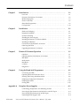
Preface
Content of this Manual
t
This book is a reference to installing, configuring, and using a GE Fanuc Series 90 -30
FIP Remote I/O Scanner (IC693BEM330).
Chapter 1. Introduction: This chapter describes the FIP Remote I/O Scanner and other
equipment that may be used with it.
Chapter 2. Installation: This chapter describes installation procedures for the Remote
I/O Scanner and I/O Nest.
Chapter 3. Remote I/O Scanner Operation: This chapter explains how a Remote I/O
Scanner interacts with the modules in its I/O Nest, how it stores data, and how it
exchanges data with the system host.
Chapter 4. Using the Hand-held Programmer: This chapter explains how to use a
Hand-held Programmer to read configuration data from the Remote I/O Scanner,
temporarily delete a module configuration, temporarily change some parameters of I/O
modules, display data, and temporarily force data.
Appendix A. Baseplate Power Supplies: This appendix gives information about the two
types of baseplate power supply that may be used in an I/O Nest.
Related Publications
For more information, refer to these publications:
Series 90-30 Hand-held Programmer Manual (GFK–0402). This book provides operating
instructions for the Hand-held Programmer.
Logicmaster 90 Software Reference Manual (GFK-0265). Reference manual which
describes program structure and defines program instructions for the Series 90–70 PLC.
t
Series 90 -70 FIP Bus ControllerUser’s Manual (GFK-1038). Reference manual for the
Bus Controller, which interfaces a FIP bus to a Series 90-70 PLC.
We Welcome Your Comments and Suggestions
At GE Fanuc Automation, we strive to produce quality technical documentation. After
you have used this manual, please take a few moments to complete and return the
Reader ’s Comment Card located on the next page.
Jeanne Grimsby
Senior technical writer
iii
Contents
Chapter 1
Chapter 2
Chapter 3
Chapter 4
Appendix A
GFK-1037B
Introduction . . . . . . . . . . . . . . . . . . . . . . . . . . . . . . . . . . . . . . . . . . . . . . .
1-1
Overview . . . . . . . . . . . . . . . . . . . . . . . . . . . . . . . . . . . . . . . . . . . . . . . . . . . . . . .
1-1
Features of the Remote I/O Scanner . . . . . . . . . . . . . . . . . . . . . . . . . . . . . . . . .
1-2
Module Description . . . . . . . . . . . . . . . . . . . . . . . . . . . . . . . . . . . . . . . . . . . . . . .
1-3
Parts of a FIP Nest . . . . . . . . . . . . . . . . . . . . . . . . . . . . . . . . . . . . . . . . . . . . . . . .
1-5
Hand-held Programmer . . . . . . . . . . . . . . . . . . . . . . . . . . . . . . . . . . . . . . . . . . .
1-9
Configuration . . . . . . . . . . . . . . . . . . . . . . . . . . . . . . . . . . . . . . . . . . . . . . . . . . . .
1-10
Installation . . . . . . . . . . . . . . . . . . . . . . . . . . . . . . . . . . . . . . . . . . . . . . . .
2-1
Hardware Packaging . . . . . . . . . . . . . . . . . . . . . . . . . . . . . . . . . . . . . . . . . . . . . .
2-1
Baseplate Installation . . . . . . . . . . . . . . . . . . . . . . . . . . . . . . . . . . . . . . . . . . . . . .
2-2
System Grounding . . . . . . . . . . . . . . . . . . . . . . . . . . . . . . . . . . . . . . . . . . . . . . . .
2-4
Installing the Power Supply . . . . . . . . . . . . . . . . . . . . . . . . . . . . . . . . . . . . . . . .
2-5
Installing the Remote I/O Scanner Module . . . . . . . . . . . . . . . . . . . . . . . . . . .
2-7
Installing I/O Modules . . . . . . . . . . . . . . . . . . . . . . . . . . . . . . . . . . . . . . . . . . . . .
2-8
Connections to the Remote I/O Scanner . . . . . . . . . . . . . . . . . . . . . . . . . . . . .
2-9
Observing the LEDs . . . . . . . . . . . . . . . . . . . . . . . . . . . . . . . . . . . . . . . . . . . . . .
2-11
Upgrading the Remote I/O Scanner . . . . . . . . . . . . . . . . . . . . . . . . . . . . . . . . .
2-12
Remote I/O Scanner Operation . . . . . . . . . . . . . . . . . . . . . . . . . . . . . .
3-1
Operation . . . . . . . . . . . . . . . . . . . . . . . . . . . . . . . . . . . . . . . . . . . . . . . . . . . . . . .
3-1
Operating Modes of the Remote I/O Scanner . . . . . . . . . . . . . . . . . . . . . . . . .
3-1
Idle Mode . . . . . . . . . . . . . . . . . . . . . . . . . . . . . . . . . . . . . . . . . . . . . . . . . . . . . . .
3-2
Ready Mode . . . . . . . . . . . . . . . . . . . . . . . . . . . . . . . . . . . . . . . . . . . . . . . . . . . . .
3-3
Run Mode . . . . . . . . . . . . . . . . . . . . . . . . . . . . . . . . . . . . . . . . . . . . . . . . . . . . . . .
3-4
I/OData . . . . . . . . . . . . . . . . . . . . . . . . . . . . . . . . . . . . . . . . . . . . . . . . . . . . . . . . .
3-5
Diagnostics . . . . . . . . . . . . . . . . . . . . . . . . . . . . . . . . . . . . . . . . . . . . . . . . . . . . . .
3-14
Using the Hand-held Programmer . . . . . . . . . . . . . . . . . . . . . . . . . . .
4-1
Connecting the HHP . . . . . . . . . . . . . . . . . . . . . . . . . . . . . . . . . . . . . . . . . . . . . .
4-2
Operating Mode and Protection Level . . . . . . . . . . . . . . . . . . . . . . . . . . . . . . .
4-3
Entering and Exiting Standalone Mode . . . . . . . . . . . . . . . . . . . . . . . . . . . . . .
4-4
Displaying Configuration Parameters . . . . . . . . . . . . . . . . . . . . . . . . . . . . . . . .
4-6
Displaying I/O Data . . . . . . . . . . . . . . . . . . . . . . . . . . . . . . . . . . . . . . . . . . . . . . .
4-10
Forcing Data . . . . . . . . . . . . . . . . . . . . . . . . . . . . . . . . . . . . . . . . . . . . . . . . . . . . .
4-15
Baseplate Power Supplies . . . . . . . . . . . . . . . . . . . . . . . . . . . . . . . . . . .
A-1
Load Ratings, Temperature, and Mounting Position . . . . . . . . . . . . . . . . . . .
A-1
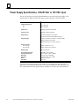
Power Supply Specifications, 120/240 VAC or 125 VDC Input . . . . . . . . . . . .
A-2
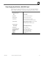
Power Supply Specifications, 24/48 VDC Input . . . . . . . . . . . . . . . . . . . . . . . .
A-3
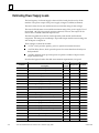
Estimating Power Supply Loads . . . . . . . . . . . . . . . . . . . . . . . . . . . . . . . . . . . .
A-4
Series 90-30 FIP Remote I/O Scanner User’s Manual – July 1996
v
restart lowapp ARestart oddapp: ARestarts for autonumbers that do not restart in
each chapter. figure bi level 1, reset table_big level 1, reset chap_big level 1, reset1
Lowapp Alwbox restart evenap:A1app_big level 1, resetA figure_ap level 1, reset
table_ap level 1, reset figure level 1, reset table level 1, reset Table 1. these
restarts oddbox reset: 1evenbox reset: 1must be in the header frame of chapter 1.
a:ebx, l 1 resetA a:obx:l 1, resetA a:bigbx level 1 resetA a:ftr level 1 resetA c:ebx, l 1
reset1 c:obx:l 1, reset1 c:bigbx level 1 reset1 c:ftr level 1 reset1 Reminders for
autonumbers that need to be restarted manually (first instance will always be 4)
let_in level 1: A. B. C. letter level 1:A.B.C. num level 1: 1. 2. 3. num_in level 1: 1. 2.
3. rom_in level 1: I. II. III. roman level 1: I. II. III. steps level 1: 1. 2. 3.
Chapter
1 Introduction
1
This chapter describes the FIP Remote I/O Scanner (IC693BEM330) and other
equipment that may be used with it.
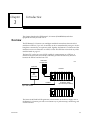
Overview
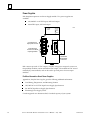
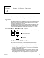
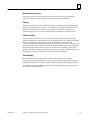
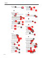
The FIP Remote I/O Scanner is an intelligent module that interfaces Series 90-30 I/O
modules to a FIP bus. Up to 19 I/O modules can be accommodated by using two 10-slot
baseplates connected by an expansion cable. Together, the Remote I/O Scanner and the
modules it serves are referred to as a FIP I/O Nest. The FIP Nest can include any of the
modules listed on page 1-7.
The host CPU can be any type of CPU capable of communicating on a FIP bus. A
module in the host (such as a FIP Bus Controller) provides the necessary interface
between the FIP bus and the host CPU.
Hand-held
Programmer
46550
Host CPU
CPU
ÎÎ
Î
Î
Î
Î
Î
ÎÎ
ÎÎÎÎ
ÎÎÎÎÎÎ
ÎÎ
Scanner
FIP
Bus
Controller
I/O Nest
FIP Bus
Up to 128 devices
Expansion Cable,
up to 50 feet (15 Meters)
ÎÎ
Î
Î
Î
ÎÎ
Î
Î
Î
ÎÎ
ÎÎÎÎ
ÎÎÎÎÎÎ
ÎÎ
The Series 90-30 Hand-held Programmer, which attaches to the Power Supply next to
the Remote I/O Scanner, provides a convenient way to perform setup, monitoring, and
control functions.
GFK-1037B
1-1
1
Features of the Remote I/O Scanner
The FIP Remote I/O Scanner performs the following basic functions:
H
H
H
H
H
controls operation of the I/O nest in the selected mode
H
H
H
H
H
H
H
retains its network configuration through loss of power
scans discrete and analog I/O modules and maintains I/O scan timing
maps I/O data to FIP application variables
detects module and system faults and reports them to the FIP network
permits Stand–Alone monitoring and limited configuration using Hand-held
Programmer
permits I/O forcing from the Hand-held Programmer
detects and records input transitions
supports FIP messaging services
responds to an external synchronization signal
can provide blinking or pulsed outputs
can provide input filtering and chatter detection
FIP Bus Interface
The Remote I/O Scanner communicates at a data rate of 1MHz.
The Remote I/O Scanner has two 9–pin male D connectors for redundant FIP bus
cables (see next page).
There are two versions of the FIP communications standard: FIP and WORLD FIP. A
DIP switch on the module is used to select the version that will be used by the Remote
I/OScanner. (The same communications method will then be used on both bus cables).
1-2
Series 90-30 FIP Remote I/O Scanner User’s Manual – July 1996
GFK-1037B
1
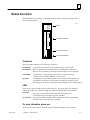
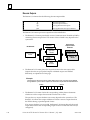
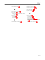
Module Description
The FIP Remote I/O Scanner is a standard Series 90–30 PLC module that plugs easily
into the rack backplane.
ÎÎÎÎÎ
ÎÎÎÎÎ
ÎÎÎÎÎ
ÎÎÎÎÎ
Î
Î
ÎÎÎÎÎ
ÎÎÎÎÎ
ÎÎÎÎÎ
ÎÎÎÎÎ
ÎÎÎÎÎ
ÎÎÎÎÎ
ÎÎÎÎÎ
ÎÎÎÎÎ
ÎÎÎÎÎ
ÎÎÎÎÎ
ÎÎÎÎÎ
ÎÎÎÎÎ
FIP CH S2
1.0 MHz
46551
CD1
TEN1
CD2
LEDs
TEN2
C
H
A
N
N
E
L
1
FIP Bus Connectors
C
H
A
N
N
E
L
2
S
Y
N
C
H
R
O
Synchro Connector
Lug for Ground Wire
Connectors
The front of the module has the following connectors:
CHANNEL 1
CHANNEL 2
9–pin male D connectors for two FIP bus cables. A bus may be
disconnected from the module without disturbing the continuity of
the bus. The second bus is a backup for the first bus; its use is optional.
SYNCHRO
Connector for a FIP synchronization cable. It requires a mating
connector such as Molex/Waldom #39–O1–4 O31.
(ground)
The lug below the Synchro connector is used for the module ground wire
(provided). The other end of the ground wire must be connected to the
mounting bolt on the lower left corner of the baseplate and to chassis ground.
LEDs
There are two pairs of LEDs at the top of the module. The upper pair is for channel 1
and the lower pair is for channel 2. Page 2-11 explains LED operation in more detail.
CD1/CD2
the green Carrier Detected LEDs indicate the presence of a
carrier-detect signal on their respective channels.
TEN1/TEN2
the red Transmission Enabled LEDs indicate the module is generating
transmissions on their respective channels.
For more information, please see:
The FIP Bus Controller Manual for information about bus installation and operation.
GFK-1037B
Chapter 1: Introduction
1-3
1
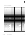
FIP Remote I/O Scanner Specifications
ClimaticOperating Conditions
Ambient Air Temperature
0 C to 60 C
RelativeHumidity
5% to 95% non-condensing
Atmospheric Pressure
80 kPa to 108 kPa
MechanicalOperatingCharacteristics
Vibration
IEC 68–2–6 Fc
Electric EnvironmentalOperatingConditions
IEC 801.2
8 kV (air). Unused FIP bus connector
must be covered by anti-static cap, such
as DCC12.
4 kV (contact)
IEC 801.3
10V/m
IEC 801.4
1 kV peak
IEC 801.5
2 kV peak (12 ohm)
EN55011(radiation)
CISPR 11
Storage and TransportCharacteristics
1-4
Storage Temperature
–40 C to 85 C
Relative Humidity
5% to 95% non-condensing
Atmospheric Pressure
66 kPa to 108 kPa
Vibration
IEC 68–2–6 Fc
Free Fall
250mm
Data Rate
1Mbit/sec
Protocol
FIP/W
orld FIP
Bus Address
0 to 127 decimal / 0 to 7F hex
Current Required from 5V Bus
609 mA
Series 90-30 FIP Remote I/O Scanner User’s Manual – July 1996
GFK-1037B
1
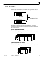
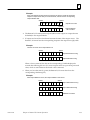
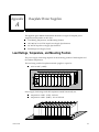
Parts of a FIP Nest
A FIP nest may consist of either one or two ten-slot or five-slot baseplates. With two
ten-slot baseplates, the FIP Remote I/O Scanner can control up to 19 I/O modules.
FIP
ÎÎ
Î
Î
Î
ÎÎÎ
ÎÎ
ÎÎÎÎÎ
ÎÎÎ
CPU Baseplate
FIP Bus
ÎÎ
Î
ÎÎ
Î
Î
Î
ÎÎ
ÎÎÎ
ÎÎ
ÎÎÎÎÎ
ÎÎÎ
Total maximum distance from main
baseplate to expansion baseplate is
50 feet (15 meters)
I/O EXPANSION CABLES
IC693CBL300 3 FT. (.9 M)
IC693CBL301 6 FT. (I.8 M)
IC693CBL302 50 FT. (15 M)
I/O Bus Terminator Plug
IC693ACC307
Expansion Baseplate
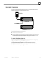
The Remote I/O Scanner is installed on the first (CPU) baseplate. An Expansion
baseplate may be connected to the CPU baseplate using an expansion cable up to 50
feet (15 Meters) in length.
Ten-Slot Baseplates with Modules
The ten-slot CPU baseplate can accommodate the FIP Remote I/O Scanner and up to
nine I/O modules. A ten-slot Expansion Baseplate can accommodate ten I/O modules.
Î
Î
Î
Î
Î
Five-Slot Baseplates with Modules
The five-slot CPU baseplate can accommodate the FIP Remote I/O Scanner and up to
four I/O modules. A five-slot Expansion Baseplate can accommodate five I/O modules.
Î
Î
Î
GFK-1037B
Chapter 1: Introduction
ÎÎ
ÎÎ
1-5
1
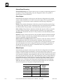
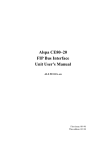
Power Supplies
Each baseplate requires its own Power Supply module. Two power supplies are
available:
H
H
120/240VAC or 125 VDC input, 30W total output
24/48 VDC input, 30W total output
POWER
SUPPLY
46552
PWR
OK
RUN
BATT
Connections for
input power source
Internal power
source for modules
requiring 24VDC
+
ÎÎÎÎ
ÎÎÎÎ
ÎÎÎÎ
ÎÎÎÎ
ÎÎÎÎ
ÎÎÎÎ
ÎÎÎÎ
Hand-held
Programmer
Connector
Both versions provide +5 VDC output, +24 VDC relay power output for circuits on
Output Relay modules, and an isolated 24 VDC output. The isolated 24 VDC is used
internally by some modules, and can be used to provide power for some input
modules.
For More Information About Power Supplies:
Appendix A, Baseplate Power Supplies, gives the following additional information:
H
H
H
H
Load Rating, Temperature, and Mounting Position
120/240VAC or 125 VDC Input Power Supply Specifications
24/48 VDC Input Power Supply Specifications
Estimating Power Supply Loads
Consult Appendix A to determine the I/O module capacity of your system.
1-6
Series 90-30 FIP Remote I/O Scanner User’s Manual – July 1996
GFK-1037B
1
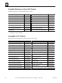
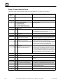
Modules for a FIP Nest
The I/O Nest can include most types of standard Series 90-30 I/O modules. Compatible modules
include those listed in the table below.
Description
Catalog #
Description
Catalog #
Input Simulator Module
IC693ACC300
Input 24VDC 16 Pt Pos (1 mS)
IC693MDL643
Input Analog 4 Pt Voltage
IC693ALG220
Input 24VDC 16 Pt Neg (1 mS)
IC693MDL644
Input Analog 4 Pt Current
IC693ALG221
Input 24VDC 16 Pt Pos/Neg
IC693MDL645
InputAnalog16Sgl/8DiffVoltage
IC693ALG222
Input 24VDC 16 Pt Pos/NegFast
IC693MDL646
InputAnalog16Sgl/8DiffCurrent
IC693ALG223
Input 24VDC 32 Pt Neg/Pos 20 mS
IC693MDL652
Output Analog 2 Pt Voltage
IC693ALG390
Input 24VDC 32 Pt Neg/Pos 2 mS
IC693MDL653
Output Analog 2 Pt Current
IC693ALG391
Input5/12VDCNeg/Pos 32 Pt
IC693MDL654
Mixed I/O 8 In/8 AC Out
IC693MAA550
Input24VDCNeg/Pos 32 Pt 1 mS
IC693MDL655
Mixed I/O 8 120VAC In/8 Relay Out
IC693MAR590
Output 12/24VDC 2A 8 Pt Pos
IC693MDL730
Mixed I/O 8 24VDC In/8 VDC Out
IC693MDD330
Output 12/24VDC 2A 8 Pt Neg
IC693MDL731
Input 120VAC 8 Pt Isolated
IC693MDL230
Output 12/24VDC 0.5A 8 Pt Pos
IC693MDL732
Input 240VAC 8 Pt Isolated
IC693MDL231
Output 12/24VDC 0.5A 8 Pt Neg
IC693MDL733
Input 120VAC 16 Pt
IC693MDL240
Output 125VDC 2A 6 Pt Isol Neg
IC693MDL734
Input 24VAC/VDC16Pt
IC693MDL241
Output 12/24VDC 0.5A 16 Pt Pos
IC693MDL740
Output 120VAC 0.5A 12 Pt
IC693MDL310
Output 12/24VDC 0.5A 16 Pt Neg
IC693MDL741
Output120/240VAC 1A 8 Pt
IC693MDL330
Output 12/24VDC 1A 16 Pt Pos Fuse
IC693MDL742
Output 120VAC .5A 16 Pt
IC693MDL340
Output 12–24VDC 32 Pt Neg Logic
IC693MDL750
Output120/240VAC 2A 5 Pt Isolated
IC693MDL390
Output 12/24VDC 32 Pt Pos Logic
IC693MDL751
Input 24VDC 8 Pt Pos Logic
IC693MDL630
Output5/12/24(TTL)32Pt
IC693MDL752
Input 125VDC 8 Pt Neg/Pos Logic
IC693MDL632
Output 12–24VDC 32 Pt Pos Logic
IC693MDL753
Input 24VDC 8 Pt Neg Logic
IC693MDL633
Output Relay 4A 8 Pt Isolated
IC693MDL930
Input 24VDC 8 Pt Neg/Pos Logic
IC693MDL634
Output Relay 8A 4/4 FormB/CIsol
IC693MDL931
Input 24VDC 16 Pt Pos Logic
IC693MDL640
Output Relay 2A 16 Pt
IC693MDL940
Input 24VDC 16 Pt Neg Logic
IC693MDL641
Mixed I/O 8 24VDC In/8 Relay Out
IC693MDR390
Input 125VDC 16 Pt Pos/Neg
IC693MDL642
GFK-1037B
Chapter 1: Introduction
1-7
1
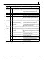
Compatible Miscellaneous Series 90-30 Products
ÁÁÁÁÁÁÁÁÁÁÁ
ÁÁÁÁÁÁÁÁÁÁÁ
ÁÁÁÁÁÁÁÁÁÁÁ
ÁÁÁÁÁÁÁÁÁÁÁ
ÁÁÁÁÁÁÁÁÁÁÁ
ÁÁÁÁÁÁÁÁÁÁÁ
ÁÁÁÁÁÁÁÁÁÁÁ
ÁÁÁÁÁÁÁÁÁÁÁ
ÁÁÁÁÁÁÁÁÁÁÁ
ÁÁÁÁÁÁÁÁÁÁÁ
ÁÁÁÁÁÁÁÁÁÁÁ
ÁÁÁÁÁÁÁÁÁÁÁ
ÁÁÁÁÁÁÁÁÁÁÁÁ
ÁÁÁÁÁÁÁÁÁÁÁÁ
ÁÁÁÁÁÁÁÁÁÁÁÁ
ÁÁÁÁÁÁÁÁÁÁÁÁ
ÁÁÁÁÁÁÁÁÁÁÁÁ
ÁÁÁÁÁÁÁÁÁÁÁÁ
ÁÁÁÁÁÁÁÁÁÁÁÁ
ÁÁÁÁÁÁÁÁÁÁÁÁ
ÁÁÁÁÁÁÁÁÁÁÁÁ
ÁÁÁÁÁÁÁÁÁÁÁÁ
ÁÁÁÁÁÁÁÁÁÁÁÁ
Á
ÁÁÁÁÁÁÁÁÁÁÁ
ÁÁÁÁÁÁÁÁÁÁÁÁ
The following products can be included in an I/O Nest.
Description
*
Catalog #
Description
Catalog #
CPU Baseplate, 10-Slot *
IC693CHS391
Hand Held Programmer & Cable
IC693PRG300
CPU Baseplate, 5-Slot *
IC693CHS397
Expansion Cable: 3 ft (1 M)
IC693CBL300
Expansion Baseplate, 10-slot
IC693CHS392
Expansion Cable: 6 ft (2 M)
IC693CBL301
Expansion Baseplate, 5-Slot
IC693CHS398
Expansion Cable: 50 ft (15 M)
IC693CBL302
Power Supply 120/240 VAC 30 W
IC693PWR321
Expansion Cable: 0.5 ft (0.15 M), shielded
IC693CBL312
Power Supply 24/48 VDC 30 W
IC693PWR322
Expansion Cable: 25 ft (8 M)
IC693CBL313
Filler Module
IC693ACC310
Expansion Cable: 50 ft (15 M), shielded
IC693CBL314
FIP Scanner can be located here
Incompatible 90–30 Products
These modules and baseplates CANNOT be used in an I/O Nest.
ÁÁÁÁÁÁÁÁÁÁÁ
ÁÁÁÁÁÁÁÁÁÁÁ
ÁÁÁÁÁÁÁÁÁÁÁ
ÁÁÁÁÁÁÁÁÁÁÁ
ÁÁÁÁÁÁÁÁÁÁÁ
ÁÁÁÁÁÁÁÁÁÁÁ
ÁÁÁÁÁÁÁÁÁÁÁ
ÁÁÁÁÁÁÁÁÁÁÁ
ÁÁÁÁÁÁÁÁÁÁÁ
ÁÁÁÁÁÁÁÁÁÁÁ
ÁÁÁÁÁÁÁÁÁÁÁ
ÁÁÁÁÁÁÁÁÁÁÁ
ÁÁÁÁÁÁÁÁÁÁÁ
ÁÁÁÁÁÁÁÁÁÁÁ
ÁÁÁÁÁÁÁÁÁÁÁ
ÁÁÁÁÁÁÁÁÁÁÁ
ÁÁÁÁÁÁÁÁÁÁÁ
ÁÁÁÁÁÁÁÁÁÁÁ
Description
1-8
Catalog #
Alpha–numeric Display Module
IC693ADC311
MixedAnalog4in/2outVoltage
IC693ALG440
MixedAnalog4in/2outCurrent
IC693ALG441
High Speed Counter Module
IC693APU300
Axis PositioningModule
IC693APU301
Axis Positioning Module (2 Axis)
IC693APU302
I/O Link Module (Slave)
IC693BEM320
I/O Link Module (Master)
IC693BEM321
Base 10–slot Remote Expansion
IC693CHS393
Base 5–slot Remote Expansion
IC693CHS399
Genius Communications Module
IC693CMM301
Enhanced Genius Comm Module
IC693CMM302
ÁÁÁÁÁÁÁÁÁÁÁ
ÁÁÁÁÁÁÁÁÁÁÁ
ÁÁÁÁÁÁÁÁÁÁÁ
ÁÁÁÁÁÁÁÁÁÁÁ
ÁÁÁÁÁÁÁÁÁÁÁ
ÁÁÁÁÁÁÁÁÁÁÁ
ÁÁÁÁÁÁÁÁÁÁÁ
ÁÁÁÁÁÁÁÁÁÁÁ
ÁÁÁÁÁÁÁÁÁÁÁ
ÁÁÁÁÁÁÁÁÁÁÁ
ÁÁÁÁÁÁÁÁÁÁÁ
ÁÁÁÁÁÁÁÁÁÁÁ
ÁÁÁÁÁÁÁÁÁÁÁ
ÁÁÁÁÁÁÁÁÁÁÁ
ÁÁÁÁÁÁÁÁÁÁÁ
ÁÁÁÁÁÁÁÁÁÁÁ
ÁÁÁÁÁÁÁÁÁÁÁ
ÁÁÁÁÁÁÁÁÁÁÁ
Description
Catalog #
CCM, RTU, SNP Communications
IC693CMM311
Base 5–slot with CPU 311
IC693CPU311
Base 5–slot with CPU 313
IC693CPU313
Base 10–slot with CPU 311
IC693CPU321
Base 10–slot with CPU 323
IC693CPU323
Series 90–30 CPU 331
IC693CPU331
Series 90–30 CPU 341
IC693CPU341
PCM300, 64K
IC693PCM300
PCM301, 85KB
IC693PCM301
PCM311 Module, 640KB
IC693PCM311
Ethernet Interface
IC693CMM321
Series 90-30 FIP Remote I/O Scanner User’s Manual – July 1996
GFK-1037B
1
Hand-held Programmer
The Series 90-30 Hand-held Programmer provides a convenient portable operator
interface to the Remote I/O Scanner and the I/O Nest.
Hand-held
Programmer
46553
FIP
Î
Î
Î
ÎÎ
Î
Î
Î Î
ÎÎ
ÎÎ
ÎÎÎÎÎ
ÎÎÎ
CPU Baseplate
FIP Bus
ÎÎ
Î
ÎÎ
Î
Î
Î
ÎÎ
ÎÎÎ
ÎÎ
ÎÎÎÎÎ
ÎÎÎ
Expansion Baseplate
The Hand-held Programmer can be used to:
H
H
Monitor, force, and unforce I/O
Be set for different levels of security that control the amount of read/write access
available from the Hand-held Programmer. Instructions for setting the security
level of the HHP are included in the Hand-held Programmer Manual.
For more information, please see:
Chapter 4, Using the Hand-held Programmer, which explains how to temporarily
configure an I/O Nest using a Hand-held Programmer.
The Hand-held Programmer Manual for basic HHP operating instructions.
The FIP Bus Controller Manual for system configuration instructions and more
detailed information about system operation.
GFK-1037B
Chapter 1: Introduction
1-9
1
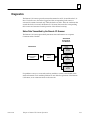
Configuration
The FIP Remote I/O Scanner may be configured in two ways.
H
H
temporarily with a Hand-held Programmer.
over the FIP network.
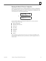
Hand-held Programmer Configuration
A Hand-held Programmer can be used to temporarily configure I/O modules so I/O
data can be monitored, forced and unforced, before the Remote I/O Scanner is
operational on the FIP network.
For more information about this type of configuration see Chapter 4, Using the
Hand-held Programmer
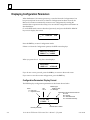
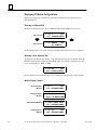
Network Configuration
A Network Configuration must be received before the Remote I/O Scanner can
exchange I/O data on the network. Until it has a valid configuration, the Remote I/O
Scanner is only capable of identifying itself on the network, then accepting the
configuration supplied.
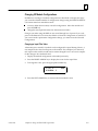
Items set up by System Configuration include.
H
H
H
H
1-10
I/O module rack and slot locations
Communications Variable (COMV) definitions and attributes.
Input filtering, chatter detection, transition detection, hold last state or default state
Output pulsing, blinking, hold last state or default state
Series 90-30 FIP Remote I/O Scanner User’s Manual – July 1996
GFK-1037B
Chapter
2 Installation
2
section level 1 1
figure bi level 1
table_big level 1
This chapter describes installation procedures for the Remote I/O Scanner and I/O
Nest.
H
H
H
H
H
H
H
H
H
Hardware Packaging
Baseplate Installation
System Grounding
Installing the Power Supply
Installing the Remote I/O Scanner Module
Installing I/O Modules
Connections to the Remote I/O Scanner
Observing the LEDs
Upgrading the Remote I/O Scanner
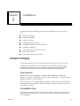
Hardware Packaging
Each module, baseplate, and prewired expansion cable is shipped in its own carton.
An expansion baseplate carton also includes an I/O bus Terminator plug, used for
terminating the expansion cable. This plug is not needed if you use the prewired
50 foot (15 meter) expansion cable, which has a built-in terminating resistor.
Visual Inspection
When you receive your equipment, carefully inspect all shipping containers for
damage. If you notice any damage, notify the carrier immediately. Save the damaged
shipping container to show the carrier.
As the consignee, it is your responsibility to register a claim with the carrier for damage
that happened during shipment. However, GE Fanuc will fully cooperate with you, if
such action is necessary.
Pre-installation Check
After unpacking the equipment, record all serial numbers. These serial numbers may
be required if you should need to contact Product Service during the warranty period
of the equipment.
GFK-1037B
2-1
2
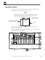
Baseplate Installation
The baseplates have standard attachment flanges for mounting on an electrical panel.
Baseplate dimensions and proper spacing are shown below.
Note
Baseplates must be mounted in the orientation shown below for proper cooling.
Mounting the baseplate on a horizontal surface may affect the power
supply load rating. See appendix A for more information.
5.59
(142)
Side View
of Module
Allow ample room for FIP bus
connectors and cables here
ÎÎ
ÎÎ
ÎÎ
ÎÎ
ÎÎ
ÎÎ
Dimensions In Inches,
(Millimeters In Parenthesis)
Baseplate
Be sure to provide enough space in front of the module to allow the FIP cables and
connectors to be installed easily..
If expansion cable is used, allow about 6 inches horizontal clearance on the right side of
the backplate for access to the connector.
*
4.00
(102)
17.44
(443)
10.43
(265)
*
16.85
(428)
9.84
(250)
15.60
(396)
4.00
(102)
*
4.00
(102)
8.60
(218)
ÎÎÎ
ÎÎ
ÎÎÎ
ÎÎ
ÎÎÎ
ÎÎ
ÎÎÎ
ÎÎ
ÎÎÎ
ÎÎ
ÎÎÎ
ÎÎ
ÎÎÎ
ÎÎ
ÎÎÎ
ÎÎ
ÎÎÎ
ÎÎ
ÎÎÎ
ÎÎ
ÎÎÎ
ÎÎ
ÎÎÎ
ÎÎ
ÎÎÎ
ÎÎ
ÎÎÎ
ÎÎ
ÎÎÎ
ÎÎ
ÎÎÎ
ÎÎ
ÎÎÎ
ÎÎ
ÎÎÎ
ÎÎ
ÎÎÎ
ÎÎ
ÎÎÎ
ÎÎ
ÎÎÎ
ÎÎ
ÎÎÎ
ÎÎ
ÎÎÎ
ÎÎ
ÎÎÎ
ÎÎ
ÎÎÎ
ÎÎ
POWER
SUPPLY
3.54
(90)
.20 DIA.
(5.08)
(TYPICAL)
5.12
(130)
FRONT VIEW
.79
(20)
*
*
2-2
Allowance for cooling
4.00
(102)
Dimensions for 5 slot rack
Series 90-30 FIP Remote I/O Scanner User’s Manual – July 1996
GFK-1037B
2
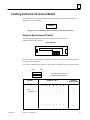
Checking the Rack-Number DIP Switches
An Expansion Baseplate is always designated “rack 1”. Before installing any modules on an
Expansion Baseplate, check the DIP switches to be sure they are set as shown below:
DIP
SW
1
2
3
1
X
X
2
X
3
X
X
4
X
X
Rack Number
Selection DIP
Switches
Closed
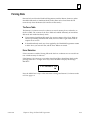
Connecting the Expansion Cable
If there is an Expansion Baseplate, it must be connected to the CPU Baseplate by an
Expansion Cable. The catalog numbers of prewired Expansion Cables are:
IC693CBL300 - 3 feet (1 meter)
IC693CBL301 - 6 feet (2 meters)
IC693CBL302 - 50 feet (15 meters)
IC693CBL312 - 0.5 feet (.15 meters), shielded
IC693CBL313 - 25 feet (8 meters)
IC693CBL314 - 50 feet (15 meters), shielded
Cables can be made to other lengths by following the instructions in the Series 90-30
PLC Installation Manual.
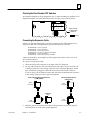
To connect an Expansion Cable:
1.
Attach the single male connector to the right of the CPU baseplate.
2.
For any cable except the 50-foot (15 Meter) prewired cables, connect the male end
of the dual connector to the mating connector on the Expansion Baseplate. Attach
the I/O Terminator plug (part number IC693ACC307) to the female connector.
If you are using a 50-ft (15M) prewired cable, attach the terminated male connector
to the mating connector on the expansion baseplate.
All Prewired Cables Except 50 foot
(15 M) Cables
Male
Connector
Male
Connector
3.
GFK-1037B
ÎÎ
Î
ÎÎ
ÎÎÎ
ÎÎ
a
Î
ÎÎ
Î ÎÎ
50 foot (15 M) Prewired
Cables Only
Male
Connector
Terminator
Plug
ÎÎ
Î
Î
ÎÎ
Male
Connector
Make the ground connections according to the instructions on the next page. Be
sure both racks are at the same ground potential.
Chapter 2: Installation
2-3
2
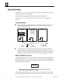
System Grounding
All components of a system must be properly grounded to ensure both personal safety
and proper operation of the equipment.
The importance of a properly-grounded system cannot be overemphasized.
See the FIP Bus Controller User’s Manual for recommendations on grounding a FIP
network.
GroundConductors
H
Ground conductors should be connected in a tree fashion with branches routed to
a central earth ground point. This ensures that no ground conductor carries
current from any other branch.
CABINET
Baseplate
MOTOR DRIVES
AND OTHER
ELECTRICAL
CONTROL
EQUIPMENT
MACHINERY
Baseplate
NOTE
EARTH
GROUND
H
CENTRAL
GROUND POINT
SIGNAL AND POWER
CONNECTIONS
ARE NOT SHOWN
Ground conductors should be as short and as large in size as possible. Braided
straps or ground cables (typically green insulation with a yellow tracer - AWG #12
(3.3 mm2) or larger) can be used to minimize resistance. Conductors must be large
enough to carry the maximum short circuit current of the path being considered.
Safety and Reference Ground
Each baseplate metal frame should be connected to earth ground. Following applicable
electical safetly codes, connect a ground strap from one of the baseplate ground lugs to
the control panel or cabinet. Use of a nut and star washer for each wire on the ground
connection lug is recommended.
Warning
The baseplate must be grounded to minimize electrical shock hazard
which may result in severe personal injury.
All baseplates grouped together in a system must have a common ground connection.
This is very important for baseplates that are not mounted in the same control cabinet.
2-4
Series 90-30 FIP Remote I/O Scanner User’s Manual – July 1996
GFK-1037B
2
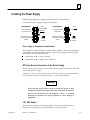
Installing the Power Supply
Install the appropriate power supply in the leftmost slot of each baseplate.
Connections for power supply wiring are shown below.
Input
IC693PWR321
+
Connections for AC/
DC power source
Internal power source
for modules requiring
24VDC
+
Input
IC693PWR322
+
100–240 VAC
50/60 HZ
125VDC
24/48 VDC
Connections for DC
power source
Internal power source
for modules requiring
24VDC
24 VDC
Output
0.8A max
+
24 VDC
Output
0.8A max
Power Supply vs. Temperature Considerations
The normal load rating of the power supply at 60_C (140_F) is 100% when a baseplate
is mounted in its normal upright position on a panel. Power supply load ratings with
the baseplate mounted horizontally are:
H
H
temperature at 25_C (77_F) - full load
temperature at 60_C (140_F) - 50% of full load
DC Power Source Connections to the Power Supply
The DC power source can be from 18 to 56 VDC for the 24/48 VDC supply or 100 to 150
VDC for the 125 VDC supply.
Connect the + and – wires from the power source to the top two protected terminals
on the terminal board (+ to the top terminal, – to the second terminal).
Warning
If the same DC power source is used to provide DC power to other
baseplates, be sure the DC input connections are identical at each rack.
Do not cross the Positive (+) and Negative (–) lines. A resulting
difference in potential can injure personnel or cause damage to
equipment.
+24 VDC Output
The bottom two terminals on the Power Supply can be used (within the power
limitations of the supply) to provide 24VDC power for input circuits.
GFK-1037B
Chapter 2: Installation
2-5
2
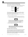
AC Power Source Connections to the Power Supply
An AC power source must be within the range of 100VAC to 240VAC at 50/60 Hz. The
120 VAC supply can range from 90 to 132 VAC, and the 240 VAC supply can range from
180 to 264 VAC. No jumper is required for selection of power source voltage.
IC693PWR321
+
Connections for AC/
DC power source
Internal power source
for modules requiring
24VDC
+
100–240 VAC
50/60 HZ
125VDC
24 VDC
Output
The power supply terminal board accepts one AWG #14 (2.1 mm2) or two AWG #16
(1.3 mm2) copper 75_ C (167_ F) wires. Each terminal can accept solid or stranded
wires, but the wires for any given terminal should be the same type. The suggested
torque for the power supply terminal board is 12 in-lbs.
Be sure the power cord plug has the correct pin configuration for 100 VAC or 240 VAC.
1.
Open the door protecting the terminal board.
2.
Make the power connections to the upper two terminals on the terminal board:
A. for 100VAC nominal input connect the hot (L1, black) and neutral (N, white) wire.
B. for 240 VAC nominal input, connect L1 and L2 of a three-wire AC power cord.
Warning
3.
If the same power source is used to provide AC power to other baseplates
in the system, ensure that all AC input connections are identical at each
rack. Do not cross Line 1 (L1) and Line 2 (L2). A resulting difference in
potential can injure personnel or cause damage to equipment.
Connect the safety ground wire (green wire) to the center ground terminal.
4.
Carefully reinstall the protective cover plate.
Warning
During normal operation with an AC power source either 120 VAC or
240 VAC is present on the AC Power Supply. The cover protects against
accidental shock hazard which could cause severe or fatal injury to the
operator or maintenance personnel.
Power Supply Line Filter for AC Power Supply
The Remote I/O Scanner and its associated hardware components have been designed
for use in industrial applications which are, in general, exempt from FCC requirements.
The AC Power Supply may not comply with FCC requirements in non-industrial
applications for conducted EMI on AC power lines. A line filter can be added in series
with the AC power line, to satisfy the FCC requirements for non-industrial applications. A
suitable line filter that will satisfy the FCC requirements for non-industrial applications is
available from GE Fanuc as part number 44A720084-001. For more information about this
filter, see the Series 90-30 Installation Manual (GFK-0356).
2-6
Series 90-30 FIP Remote I/O Scanner User’s Manual – July 1996
GFK-1037B
2
Installing the Remote I/O Scanner Module
The FIP Remote I/O Scanner Module must be installed in the slot next to the Power
Supply of the CPU baseplate.
Caution
Rack power should be OFF when installing or removing the module.
Setting the Board Address DIP Switch
Before installing the Remote I/O Scanner, it may be necessary to set its
address-selection DIP switches.
Back of Module
Switch positions are numbered 1 through 8. Switch 1 selects FIP or World FIP protocol,
as shown in the table below.
Set switches 2 through 8 to represent a board network address from 0 to 127 (decimal).
MSB
1
LSB
8
" (up, away from board) = 0
# (down, toward board) = 1
Switch 1
1
# FIP = 1
" World FIP = 0
GFK-1037B
Chapter 2: Installation
Address
Represented
Switches 2 to 8
2
3
4
5
6
7
8
"
"
.
.
.
.
.
.
#
"
"
.
.
.
.
.
.
#
"
"
.
.
.
.
.
.
#
"
"
.
.
.
.
.
.
#
"
"
.
.
.
.
.
.
#
"
"
.
.
.
.
.
.
#
"
#
.
.
.
.
.
.
#
O
1
.
.
.
.
.
.
127
2-7
2
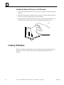
Installing the Remote I/O Scanner on the Baseplate
1.
Grasp the module with the front cover toward you and the rear hook facing away
from you.
2.
Align the module with its intended slot and connector. Tilt the module upward so
that its top rear hook engages the slot on the baseplate.
3.
Swing the module downward until the connectors mate and the locking lever on
the bottom of the module snaps into place, engaging the baseplate notch.
ÎÎÎÎÎÎÎÎÎÎÎ
ÎÎÎÎÎÎÎÎÎÎÎ
ÎÎÎÎÎÎÎÎÎÎÎ
ÎÎÎÎÎÎÎÎÎÎÎ
ÎÎ
ÎÎÎÎÎÎÎÎÎÎÎ
ÎÎ
ÎÎ
ÎÎÎÎÎÎÎÎÎÎÎ
ÎÎ
ÎÎ
ÎÎÎÎÎÎÎÎÎÎÎ
ÎÎ
ÎÎÎÎÎÎÎÎÎÎÎ
a43055
Î
Î
Installing I/O Modules
Install I/O modules on the baseplate as shown at the top of the page. Refer to the I/O
Modules User’s Manual for information about completing field wiring to the I/O
modules.
2-8
Series 90-30 FIP Remote I/O Scanner User’s Manual – July 1996
GFK-1037B
2
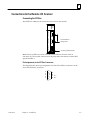
Connections to the Remote I/O Scanner
Connecting the FIP Bus
ÎÎÎÎ
ÎÎÎÎ
ÎÎÎÎ
Î
Î
ÎÎÎÎ
ÎÎÎÎ
ÎÎÎÎ
ÎÎÎÎ
ÎÎÎÎ
ÎÎÎÎ
ÎÎÎÎ
ÎÎÎÎ
ÎÎÎÎ
ÎÎÎÎ
Attach FIP bus cable(s) to the connectors on the front of the module.
FIP CH S2
1.0 MHz
CD1
TEN1
CD2
TEN2
C
H
A
N
N
E
L
1
C
H
A
N
N
E
L
2
Connect FIP bus
cable(s) here.
S
Y
N
C
H
R
O
Connect ground strap here
Note: If only one FIP bus is used, cover the unused FIP bus connector with an
anti-static cap. The unused connector must be protected in this manner to meet IEEE
specification 801.2.
Pin Assignments for the FIP Bus Connectors
The diagram below shows pin assignments for both of the FIP bus connectors on the
front of the Remote I/O Scanner.
5
4
3
2
1
GFK-1037B
Chapter 2: Installation
9
8
7
6
D–
D+
2-9
2
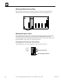
Attaching the Module Ground Strap
Attach the grounding strap to the spade connector on the front of the module (see
illustration below for location), and to the baseplate’s lower left mounting screw.
Attaching the Synchro Cable
The Synchro signal can be used to synchronize the timing information used by all FIP
I/O components on the network. If used, the Synchro cable attaches to the lower
connector on the front of the module. The mating connector for the Synchro cable should
be Molex/Waldom #39-01-4031 or an equivalent connector.
Pin Assignments for the Synchro Cable Connector
The diagram below shows pin assignments for the Synchro connector.
SYNC +
SYNC –
SHIELD
1
2
3
Synchro Connector
Ground Strap Connector
2-10
Series 90-30 FIP Remote I/O Scanner User’s Manual – July 1996
GFK-1037B
2
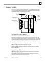
Observing the LEDs
When power is applied, the LEDs on the Remote I/O Scanner and the Power Supply
on the CPU baseplate indicate operating status. The Remote I/O Scanner controls the
OK and RUN LEDs on the CPU baseplate Power Supply.
LED On Indications
Power Supply
Operating
POWER
SUPPLY
OK
RUN
Remote I/O Scanner
is operating (but may
not be configured)
ÎÎÎÎÎ
ÎÎÎÎÎ
ÎÎÎÎÎ
ÎÎÎÎÎ
Î
Î
ÎÎÎÎÎ
ÎÎÎÎÎ
ÎÎÎÎÎ
ÎÎÎÎÎ
ÎÎÎÎÎ
ÎÎÎÎÎ
ÎÎÎÎÎ
ÎÎÎÎÎ
ÎÎÎÎÎ
ÎÎÎÎÎ
ÎÎÎÎÎ
ÎÎÎÎÎ
PWR
FIP CH S2
1.0 MHz
TEN1
CD2
TEN2
BATT
C
H
A
N
N
E
L
Remote I/O Scanner
is in Run mode
CD1
Carrierdetect
SIgnal is
present
Remote I/O
Scanner is
transmitting
1
+
C
H
A
N
N
E
L
2
Power Supply LEDs on the CPU Baseplate
PWR: Indicates correct operation of the Power Supply.
OK: Goes on when the Remote Scanner passes its powerup diagnostics. This LED
stays on unless a backplane failure or Remote I/O Scanner failure occurs. Note that this
LED does NOT indicate whether or not the Remote I/O Scanner has been configured.
RUN: This LED is on when the Remote Scanner is in its running mode. On an
expansion rack, the Run LED is on whenever the OK LED is on in the main rack and
the power supply of the expansion rack is also on.
BATT: The Battery Status LED is not used. It is always off.
If there is an Expansion Baseplate, its PWR and OK LEDs come on as soon as the
Expansion Baseplate receives power. The RUN LEDs come on as soon as the Main
Rack OK LED comes on.
Remote I/O Scanner LEDs
CD1, CD2: The green carrier-detect LEDs indicate the presence of a carrier-detect
signal on their respective channels.
TEN1, TEN2: The red Transmit Enabled LEDs flicker rapidly when the module is
generating transmissions on their respective channels.
GFK-1037B
Chapter 2: Installation
2-11
2
Upgrading the Remote I/O Scanner
To upgrade the Remote I/O Scanner firmware, connect the serial port of a personal
computer to the HHP connector (on the CPU baseplate Power Supply). This requires
an RS-422/RS-485 to RS-232 converter. Download the contents of the upgrade diskette
to the Remote I/O Scanner, using the instructions included with the upgrade diskette.
By default, communications will be at 19.2 kBaud (8 bits/character, odd parity, one stop
bit).
2-12
Series 90-30 FIP Remote I/O Scanner User’s Manual – July 1996
GFK-1037B
Chapter
3 Remote I/O Scanner Operation
3
section level 1 1
figure bi level 1
table_big level 1
This chapter explains how a Remote I/O Scanner interacts with the modules in its I/O
Nest, how it stores data, and how it exchanges data with the system host.
Operation
The primary runtime operations of the Remote I/O Scanner are to accept data from the
FIP bus and pass this to the corresponding output modules and to acquire updated
input data for transmission onto the FIP bus.
If a problem occurs (or is corrected) with any module or circuit, it is included in the status
information regularly transmitted by the Remote I/O Scanner. Such module problems do
not affect operation of the Remote I/O Scanner or its communications on the network.
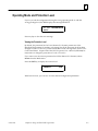
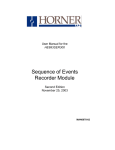
Operating Modes of the Remote I/O Scanner
Stand
alone
Idle
Stand
alone
Ready
Idle
Ready
Run
The Remote I/O Scanner can operate in the following
modes:
H
H
H
H
H
Idle Mode
Standalone Idle Mode
Ready Mode
Standalone Ready Mode
Run Mode
How Communications Affect Operating Mode
The operating mode of the Remote I/O Scanner depends on whether or not it is
communicating with the FIP network.
A. If it is communicating with the FIP network, the Remote I/O Scanner may be commanded by the network controller to operate in Idle, Ready, or Run mode. An HHP may be
used to change the operating mode from Ready to Standalone Ready and back.
B. If a FIP network is not present, the Remote I/O Scanner remains in Idle mode at
powerup. A Hand-held Programmer may be used to change the operating mode
from Idle to Standalone Idle and back.
C. If a FIP network is present but communications between the Remote I/O Scanner
and the network controller have been lost, the Remote I/O Scanner returns from
Run mode back to Ready mode. The Hand-held Programmer may be used to
change the operating mode from Ready to Standalone Ready and back.
GFK-1037B
3-1
3
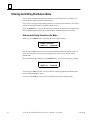
Idle Mode
Stand
alone
Idle
Stand
alone
Ready
Idle
Ready
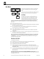
In Idle mode, the Remote I/O Scanner can indicate its
presence on the FIP bus, but it cannot exchange I/O
data.
There are two sub-types of Idle mode: Idle mode and
Standalone Idle mode. Both are described below.
Idle Mode
The Remote I/O Scanner is in Idle mode after it is
powered up, but when no configuration or mode
change commands have been received from the
network. During normal operation, the Remote I/O
Scanner is only in Idle mode during the first few seconds after powerup. If a FIP
network controller is not present, the Remote I/O Scanner remains in Idle mode. In
Idle mode:
Run
h
h
password protection is level 4.
h
the I/O default data and, if force retention is enabled, the force conditions are
recovered from non-volatile memory for later use.
all I/O validator data is set to “invalid”.
a Hand-held Programmer can be used to monitor I/O and validators and module
configuration.
h
h
h
the Remote I/O Scanner scans I/O modules for identification information and input
data only: all outputs remain off.
The Remote I/O Scanner can receive a system configuration from the FIP network.
No forcing via FIP messages is permitted.
After receiving a system-level configuration the Remote I/O Scanner can be commanded
(from the network) to go to Ready mode. If a Hand-held Programmer is attached and
the MODE and # keys are pressed simultaneously, the Remote I/O Scanner goes to
Standalone Idle mode instead.
Standalone Idle Mode
In Standalone Idle mode:
h
h
h
h
The Remote I/O Scanner ignores any messages from the FIP network.
h
I/O data may be monitored and/or forced, The Remote I/O Scanner scans default
and/or forced data to all installed I/O modules. Scanning is independent of FIP
network activity.
HHP communications are permitted at 9600 baud.
default password protection is set to level 4.
limited configuration changes may be entered from a Hand-held Programmer.
Configurable features are the rack and slot locations of I/O modules and discrete input
module filter values.
Standalone Idle mode may be exited by pressing the MODE and # keys on the
Hand-held Programmer simultaneously. At that time, the Force table is again cleared and
all outputs are set to zero.
3-2
Series 90-30 FIP Remote I/O Scanner User’s Manual – July 1996
GFK-1037B
3
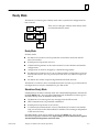
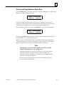
Ready Mode
The Remote I/O Scanner goes to Ready mode when a system-level configuration has
been received.
Stand
alone
Idle
Idle
Stand
alone
Ready
Ready
There are two subtypes of Ready mode: Ready mode
and Standalone Ready mode.
Run
Ready Mode
In Ready mode:
h
the Remote I/O Scanner waits for permission to enter Run mode from the FIP
network controller.
h
h
default password protection is level 2.
h
h
configuration can NOT be changed by a Hand-held Programmer.
h
the Remote I/O Scanner accepts forcing information from the network.
a Hand-held Programmer can be used to monitor I/O and validators and module
configurations.
the Remote I/O Scanner scans I/O in accordance with the configuration it received
from the FIP network. If it was previously in Idle mode, any unforced outputs are
set to 0.
The Remote I/O Scanner can be commanded (from the network) to go to Idle mode for
reconfiguration or it may be commanded to go to Run mode.
Standalone Ready Mode
If the Remote I/O Scanner is in Ready mode with a Hand-held Programmer attached and
the HHP MODE and # keys are pressed simultaneously, the Remote I/O Scanner goes to
Standalone Ready mode. In Standalone Ready mode:
h
h
h
h
The Remote I/O Scanner ignores any messages from the FIP network.
HHP communications are permitted at 9600 baud.
default password protection is set to level 2.
I/O data may be monitored and/or forced, The Remote I/O Scanner scans default
and/or forced data to all of the installed I/O modules. The scanning is independent
of FIP network activity.
Standalone Ready mode may be exited by pressing the MODE and # keys on the
Hand-held Programmer simultaneously. Upon exiting, any forces that have been applied
with the Hand-held Programmer remain in effect.
GFK-1037B
Chapter 3: Remote I/O Scanner Operation
3-3
3
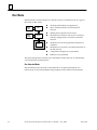
Run Mode
In Ready mode, when the Remote I/O Scanner receives a command to do so, it goes to
Run mode. In Run mode:
Stand
alone
Idle
Idle
Stand
alone
Ready
Ready
Run
h
h
all configured modules are operational
h
h
default password protection is level 2.
h
the Remote I/O Scanner generates and observes
validators.
h
the Remote I/O Scanner can communicate fully on
the FIP network.
h
h
configuration changes are not permitted.
data is communicated to and from the FIP
network.
the Remote I/O Scanner scans I/O in accordance
with the configuration it received from the FIP
network.
HHP use is not permitted.
The mode changes back to Ready upon command from the network, or if the Remote
I/O Scanner loses communications.
Run Unlocked Mode
Run Unlocked mode is the same as described above, except that the Remote I/O
Scanner does not check refreshment and promptness status in Run Unlocked mode.
3-4
Series 90-30 FIP Remote I/O Scanner User’s Manual – July 1996
GFK-1037B
3
I/O Data
The Remote I/O Scanner scans I/O modules in its I/O Nest in the same manner in
which a PLC CPU scans I/O modules in the PLC. I/O updates and data types are
described in detail on the following pages.
Remote I/O Scanner Data Tables
The Remote I/O Scanner stores I/O data, as well as additional data representing forced
conditions and “validator” status, in separate memory areas.
DataDescription
Data Type
Displayedon
HHP
Series 90-70
PLC Data Type
Remote I/O
Scanner Data
Type
discrete input states
I
%I
IF
discrete output states
Q
%Q
QF
analog input values
AI
%AI
AIF
analog output values
AQ
%AQ
AQF
discrete input validators
IV
outputvalidators
QV
analog input validators
AIV
analog output validators
AQV
IVF
Fault/NoFault
Contacts
QVF
AIVF
AQVF
unforced discrete input states
I
unforced discrete output states
Q
unforced analog input states
AI
unforced analog output states
AQ
unforced discrete input validators
IV
unforced discrete output validators
QV
unforced analog input validators
AIV
unforced analog output validators
AQV
In the Remote I/O Scanner, the I/O state and validator tables contain the actual input
and output data. The unforced I/O state and validator tables contain the same
information as in the actual I/O state and validator tables, except that they reflect the
states and validators without regard to the effect of applied forces.
Displaying Data with a Hand-held Programmer
The Hand-held Programmer can read data directly from the Remote I/O Scanner. If the
Remote I/O Scanner is in Standalone Idle or Standalone Ready mode, the Hand-held
Programmer can also force the states of I/O data. Validators are forced to “valid” for
forced inputs.
GFK-1037B
Chapter 3: Remote I/O Scanner Operation
3-5
3
Synchronous or Non-synchronous Scanning
I/Oscanning for the devices on the network may be set up in the Network
Configuration as synchronous. Synchronous operation means that devices on the
network are capable of maintaining a local time and date which is coherent with a
system clock. Scanning is referenced to the network timing as described below.
To use this feature, the Remote I/O Scanner must be connected to other devices and to
a system clock pulse source by a cable that attaches to the Synchro terminals on the
front of the module.
Updating the Remote I/O Scanner Time and Date
The Remote I/O Scanner receives a message containing the time and date from
another FIP subscriber (usually a CPU) which is in charge of maintaining an accurate
network time. The Remote I/O Scanner stores this information until it receives the next
Synchro signal (via the Synchro cable). The Remote I/O Scanner then synchronizes its
time-of-day clock according to this new time and date information.
The frequency with which the time and date information is sent to the Remote I/O
Scanner is set up in the Network Configuration.
Frequency of Synchro Pulse
The frequency of the Synchro pulse is called its “periodicity”. Periodicity is also set up
in the Network Configuration. The periodicity range is 1 second to 10 seconds.
Status Information Sent to the CPU
If the Remote I/O Scanner does not receive a new time-and-date message or detect a
Synchro pulse within the configured period, it keeps operating using the existing time
and date. However, it notifies the CPU that it is using the “non-synchronous” time and
date by setting a bit in the status information (described later in this chapter).
3-6
Series 90-30 FIP Remote I/O Scanner User’s Manual – July 1996
GFK-1037B
3
Discrete Inputs
The Remote I/O Scanner has the following discrete input tables:
I
IV
IF
IFV
discrete input states
discrete input validators
force applied: discrete inputs
force applied: discrete input validators
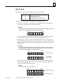
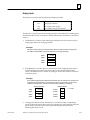
The Remote I/O Scanner processes input data as described below.
1.
the Remote I/O Scanner scans input and I/O modules in the I/O Nest and then
places discrete input data in its discrete input table
Example:
The Remote I/O Scanner reads the inputs configured to use I0001 through I0008 during
its input scan. It places the data into its discrete input table:
I0001
I0008
1
0
0
1
0
1
0
0
If set up by the Network Configuration, the Remote I/O Scanner may also process
inputs for filtering, chatter detection, and time-stamping. See page 3-9.
2.
if the Remote I/O Scanner detects a module fault while reading the input data, it
defaults all inputs for that module to the configured on/off or last state, and marks
them as “invalid” by setting to the input validator (IV) locations associated with
those inputs.
Example:
If the module supplying inputs I0001 through I0008 is configured to default inputs OFF,
and the module is subsequently removed, the Remote I/O Scanner sets its inputs OFF
and also sets the corresponding input validator data:
I0001
0
I0008
0
0
0
0
0
0
IV0001
1
3.
1
0
Inputs set to OFF
IV0008
1
1
1
1
1
1
Input validators
set to “invalid”
Discrete inputs may be forced. The Remote I/O Scanner sets the corresponding
inputs in the input table. When a force is removed, the input table displays the
normal data following the next I/O scan.
Example:
The HHP is used to force input I0008 to 1.
I0001
GFK-1037B
I0008
0
0
0
0
0
0
0
0
Input Data before forcing
0
0
0
0
0
0
0
1
Input Data after forcing
Chapter 3: Remote I/O Scanner Operation
3-7
3
4.
When you force the state of a point, the Remote I/O Scanner also forces the
corresponding validator (IVF) to the valid state.
Example:
When the HHP forces input I0008, the input validator is also forced.
I0001
I0008
0
0
0
0
0
0
0
0
Input Data before forcing
0
0
0
0
0
0
0
1
Input Data after forcing
1
1
1
1
1
1
1
0
Validator Data after forcing
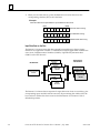
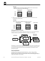
Input Data Sent on the Bus
The Remote I/O Scanner treats the data acquired from each Input or Input/Output
module as an “application variable”. It combines these (input) application variables into
one or more Communications Variables (COMVs). It periodically transmits these
COMVs on the FIP Network.
FIP Network
Application
Variable
Application
Variable
Application
Variable
Communications
Variable
Validity
Qualifiers
Validity
Qualifiers
Validity
Qualifiers
Series 90-30
I/O Modules
Input or I/O
Module
Input or I/O
Module
Input or I/O
Module
The Remote I/O Scanner honors requests for input data even when it is invalid (e.g. the
corresponding input module has been removed). By monitoring the validity data, the
host can know whether the data it receives from the Remote I/O Scanner is real or
defaulted input data.
3-8
Series 90-30 FIP Remote I/O Scanner User’s Manual – July 1996
GFK-1037B
3
Optional Input Processing
If set up by Network Configuration discrete inputs can be processed for filtering,
chatter detection, and time-stamping. These features are described below.
Filtering
A discrete input module or mixed I/O module can be configured for input filtering. In
the Network Configuration, select 1, 2, or 4 samples as the value for all inputs on the
module. For example if you selected 2, each input on this module would need to
remain changed for two successive samples before the change is considered valid.
Chatter Detection
Individual input circuits can be set up in the Network Configuration as chattering
inputs. The Remote I/O Scanner processes all chattering inputs on a module identically.
This processing occurs after the inputs are filtered (see above). The Network
Configuration specifies a time period which is a multiple (0, 100, 1000, or 10,000) of the
10 mS acquisition rate. It also defines the number of transitions that must occur during
the selected time period before the input is considered to be chattering. If the input
changes state more than the specified number of times during the selected time period,
the Remote I/O Scanner informs the CPU that the input is chattering.
Time-Stamping
Individual input circuits and/or their validators can be set up in the Network
Configuration for time-stamping. If an input set up for time-stamping changes after
filtering, the Remote I/O Scanner supplies the time and date of the change to the host.
The format for the time and date stamp and for the State Change message to the host
are defined in the FIP Standard.
GFK-1037B
Chapter 3: Remote I/O Scanner Operation
3-9
3
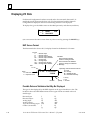
Discrete Outputs
The Remote I/O Scanner has the following discrete output tables:
Q
QV
QF
QVF
discrete output states
discrete output validators
force applied: discrete outputs
force applied: discrete output validators
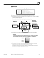
The Remote I/O Scanner processes output data as described below.
1.
The Remote I/O Scanner periodically receives Communications Variables (COMVs)
containing discrete output data. The content of these COMVs may depend on the
system host.
Series 90-30
Output and I/O
Modules
Application
Variable
Application
Variable
Application
Variable
FIP Network
Output or I/O
Module
Output or I/O
Module
Output or I/O
Module
Communications
Variable
Validity
Qualifiers
Validity
Qualifiers
Validity
Qualifiers
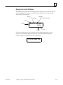
2.
The Remote I/O Scanner places the output data into its discrete output table.
Outputs that are set up as pulsed outputs or blinked outputs are handled
differently, as explained on a later page.
Example:
The Remote I/O Scanner receives output data from the host, including outputs Q0009
through Q0016. It places those outputs into its discrete output table as illustrated below:
Q0009
0
3.
Q0016
0
1
1
0
1
1
1
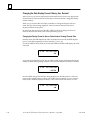
The Remote I/O Scanner checks the corresponding validity data to determine
whether or not the output data received from the host is valid.
The specific way output validators are set may depend on the system host. The
Remote I/O Scanner sets output validators if it doesn’t receive output data from
the FIP bus during a specified period of time.
If an output validator is set to invalid, the Remote I/O Scanner discards the actual
output data and sets the corresponding output to OFF or holds their last state (as
configured).
3-10
Series 90-30 FIP Remote I/O Scanner User’s Manual – July 1996
GFK-1037B
3
Example:
If the host stopped sending outputs, the Remote I/O Scanner could set all discrete
outputs to off (as shown here) or to their last state, and also set the corresponding
output validator data:
Q0009
Q0016
0
0
0
0
0
0
0
QV0009
1
0
Outputs set to OFF
QV0016
1
1
1
1
1
1
Output validators
set to “invalid”
1
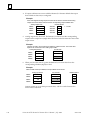
4.
The Remote I/O Scanner passes outputs (either actual outputs or outputs that are
defaulted) to the output modules.
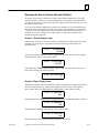
5.
If outputs are forced, the forced state becomes the state of the output circuit. The
Remote I/O Scanner sets the corresponding outputs in the output force (QF) table.
Example:
The HHP is used to force output Q0012 to 0.
Q0009
Q0016
0
0
1
1
0
1
1
1
0
0
1
0
0
1
1
1
Output Data before forcing
Output Data after forcing
When a force is removed, the data in the corresponding I/O table displays the
normal data following the next I/O scan. Outputs retain an up–to–date processed
value, which is used whenever the forced value is removed.
6.
When you force the state of a point, the Remote I/O Scanner also forces the
corresponding validator (QVF).
Example:
When output Q0012 is forced, the output validator is also forced.
Q0009
GFK-1037B
Q0016
0
0
1
1
0
1
1
1
Output Data before forcing
0
0
1
0
0
1
1
1
Output Data after forcing
1
1
1
0
1
1
1
1
Validator Force data
Chapter 3: Remote I/O Scanner Operation
3-11
3
Optional Output Processing
Normal/Temporizing: Each output can be set up as a normal or temporizing output. If
an output is set up as temporizing, it may be configured to behave as a pulsed or
delayed output as described below.
Pulsed Outputs
Individual discrete outputs can be set up in the Network Configuration to be pulsed
outputs. When the Remote I/O Scanner receives the output state for a pulsed output
from the CPU, it processes the output as defined by the following configuration
parameters.
Polarity: This parameter determines whether the point will respond to positive-edge
or negative-edge transitions of the commanded state. The output itself will respond in
the same direction. This parameter can be individually selected for each point.
Pulse or Delay: This parameter determines whether the response will be a true pulse
or simply a delayed transition. A delayed response will return to its original state
whenever the commanded state does so. This parameter can be individually selected
for each point.
Duration: If Pulse is selected (see above), this parameter defines the maximum length
of the pulse. If Delay is selected, this parameter defines the delay time. The duration
selection is applied to all points on the module.
Return to Zero or Non-Return to Zero: This parameter is used only if Pulse is selected.
Choosing Return to Zero will cause the pulse to terminate whenever the state
commanded by the CPU does back to its original state. Choosing Non-Return to Zero
will cause the pulse to last for its configured duration (see item above) regardless of
whether the CPU changes the output’s commanded state. This parameter can be
individually selected for each point.
Blinked Outputs
Individual discrete outputs can be set up in the Network Configuration to be blinked
outputs. For blinked outputs, the Remote I/O Scanner synchronizes output data
transitions with an internal clock which may be synchronized with the network system
clock. Operation of blinked outputs depends on the state of the output bit itself and on
the state of another bit sent by the CPU, called the blink bit. There is a unique blink bit
for each blinked output. The table below shows the relationship between the state of
the blink bit and the state of the output bit. A blinked output always blinks while its
blink bit is set to 1. The state of the output point bit determines the rate of blinking.
While the state of the output bit is 0, the physical output blinks at 0.5 Hz. While the
state of the output bit is 1, the physical output blinks at 2.0 Hz.
Blink Bit
State Bit
Physical
Discrete
Output
0
0
0
0
1
1
1
0
2 Hz Blink
1
1
0.5 Hz Blink
Communications Variable
3-12
Series 90-30 FIP Remote I/O Scanner User’s Manual – July 1996
GFK-1037B
3
Analog Inputs
The Remote I/O Scanner has the following analog input tables.
AI
AIV
analog input values
analog input validators
AIF
AIVF
force applied: analog inputs
force applied: analog input validators
The Remote I/O Scanner processes analog input data as described below (analog input
modules filter data locally, so the data is already filtered when the Remote I/O Scanner
reads it.)
1.
The Remote I/O Scanner scans analog input modules in the I/O Nest and places
analog input data in its analog input table
Example:
During the analog input scan, the Remote I/O Scanner reads the inputs configured to
use AI001 through AI004. It places the inputs into its analog input table:
2.
AI001
57143
AI002
16385
AI003
36884
AI004
1141
If the Remote I/O Scanner detects a module fault while reading the input data, it
defaults all inputs associated with that module to their default/hold last state
values, and marks them as “invalid” by setting to one the AIV locations associated
with those inputs.
Example:
If the module supplying inputs AI001 through AI004 were removed and the module were
configured for Hold Last State, the Remote I/O Scanner would hold the inputs for that
module to their last values, and set the corresponding validators to invalid (1).
Analog Input Data
3.
GFK-1037B
Validator Status
AI001
57143
AIV001
1
AI002
16385
AIV002
1
AI003
36884
AIV003
1
AI004
1141
AIV004
1
1 = invalid
Analog inputs may be forced. The Remote I/O Scanner sets the corresponding
inputs in the analog input table, which also contains the current states of unforced
inputs. When a force is removed, the input table displays the normal data
following the next I/O scan.
Chapter 3: Remote I/O Scanner Operation
3-13
3
Example:
The HHP is used to force analog input AI002 to a different value. The forced value
replaces the actual value in the analog input table:
Analog Input Data
before forcing
4.
Analog Input Data
after forcing
AI001
57143
57143
AI002
16385
500
AI003
36884
36884
AI004
1141
1141
When you force the state of a point, the Remote I/O Scanner also forces the
corresponding validator (IVF).
Example:
When the HHP forces input AI002 its input validator is also forced.
Analog Input Data
before forcing
Analog Input Data
after forcing
Validator Status
AI001
57143
57143
1
AI002
16385
500
0
AI003
36884
36884
1
AI004
1141
1141
1
Analog Input Data Sent on the Bus
The Remote I/O Scanner combines analog input data into one or more Communications
Variables (COMVs). It periodically transmits these COMVs on the Network.
FIP Network
Application
Variable
Application
Variable
Application
Variable
Communications
Variable
Validity
Qualifiers
Validity
Qualifiers
Validity
Qualifiers
Series 90-30
I/O Modules
Input or I/O
Module
Input or I/O
Module
Input or I/O
Module
The Remote I/O Scanner honors requests for input data even when it is invalid (e.g. the
corresponding input module has been removed). By monitoring the validity data, the
host can know whether the data it receives from the Remote I/O Scanner is real or
defaulted input data.
Smart Analog Modules
In addition to the analog input data described above, “smart” analog modules
(IC693ALG392 and ALG442) use 5 bytes of discrete input data, which is used for
diagnostic status bits. If the first byte of this data is not zero, each analog input validator
(AIV) for the module is set to invalid.
3-14
Series 90-30 FIP Remote I/O Scanner User’s Manual – July 1996
GFK-1037B
3
Analog Outputs
The Remote I/O Scanner has the following analog output tables.
AQ
AQV
AQF
analog output values
analog output validators
force applied: analog outputs
AQVF
force applied: analog output validators
The Remote I/O Scanner processes analog output data as described below.
1.
The Remote I/O Scanner periodically receives Communications Variables (COMVs)
containing analog output data.
The content of these COMVs may depend on the system host.
FIP Network
Series 90-30
Output and I/O
Modules
Application
Variable
Application
Variable
Application
Variable
Output or I/O
Module
Output or I/O
Module
Output or I/O
Module
Communications
Variable
Validity
Qualifiers
Validity
Qualifiers
Validity
Qualifiers
2.
The Remote I/O Scanner places the output data into its Analog Output table.
Example:
The Remote I/O Scanner receives output data from the host, including outputs AQ005
through AQ008. It places those outputs into its AQ data table as illustrated below:
3.
AQ005
114
AQ006
72
AQ007
106
AQ008
93
The Remote I/O Scanner checks the corresponding validity data to determine
whether or not the output data received from the host is valid.
The Remote I/O Scanner sets output validators if it doesn’t receive output data
from the FIP bus during a specified period of time.
GFK-1037B
Chapter 3: Remote I/O Scanner Operation
3-15
3
4.
If output validators are set to invalid the Remote I/O Scanner defaults the output
data or holds its last state, as configured.
Example:
If the host stopped sending outputs, the Remote I/O Scanner would hold all analog
outputs at their last values and also set the corresponding output validator data:
Analog Output Data
114
AQ005
72
AQ006
106
93
AQ007
AQ008
5.
Validator Status
1 = invalid
1
1
AQV005
AQV006
AQV007
1
1
AQV008
Analog outputs may be forced. The Remote I/O Scanner sets the corresponding
outputs in the output force (AQF) table. The forced value becomes the value of the
output circuit.
Example:
The HHP is used to force analog input AQ007 to a different value. The forced value
replaces the actual value in the analog output table:
Analog Output Data
114
AQ005
114
AQ006
72
72
AQ007
106
93
75
AQ008
6.
Forced Data
93
When you force the state of a point, the Remote I/O Scanner also forces the
corresponding validator (AQVF) to valid.
Example:
When the HHP forces input AQ007, its output validator is also forced.
Analog Input Data
Forced Data
Validator Status
AQ005
114
114
1
AQ006
72
72
1
AQ007
106
75
0
AQ008
93
93
1
Outputs retain an up–to–date processed value, which is used whenever the
forced value is removed.
3-16
Series 90-30 FIP Remote I/O Scanner User’s Manual – July 1996
GFK-1037B
3
Diagnostics
The Remote I/O Scanner provides status information for each I/O module in the I/O
Nest. If a fault occurs, the fault is logged and the corresponding fault contact is
activated. It remains activated only while the fault is in effect. After the condition that
caused the fault is corrected, the Remote I/O Scanner deactivates the corresponding
fault contact and resumes normal operation of the affected circuit(s).
Status Data Transmitted by the Remote I/O Scanner
The Remote I/O Scanner periodically transmits status information as a separate
Communications Variable.
All Installed
Series 90-30
I/O Modules
Output
Module
Output
Module
FIP Network
Status
Communication
Variable
Modules’
Status
I/O
Module
I/O
Module
Input
Module
Input
Module
If a problem occurs (or is corrected) with any module or circuit, it is included in this
status information. Such module problems do not affect the operation of the Remote
I/OScanner, or its communications on the network.
GFK-1037B
Chapter 3: Remote I/O Scanner Operation
3-17
3
Remote I/O Scanner Status Data Format
The format of the status (IOSTAT) COMV sent by the Remote I/O Scanner is shown below.
Offset
(Byte #)
0
1
2, 3
4
5
6
Content
1
0
RemoteI/O Scanner Identification
0 to 65535
Version number
00 = Non-operationalfault
01 = Operational: Idle
02 = Operational: Ready
03 = Operational: Running Locked
04 = Operational: Running Unlocked
Operating mode
Bit
3-18
Status Bits
0
Loss of FIP Status bits
1
reserved
2
I/O are currently forced
Set when any points are forced.
3
HHP forcing is permitted
Set when it is possible to force I/O with the HHP. Operating mode changes are not allowed.
4
HHP password violation
Set when a password access violation occurs
5
Configuration rejected by scheduler
Set when the most recent CONFIG_ENABLE command
failed because the downloaded configuration could not
be used to build a valid internal schedule table.
6
reserved
7
Ready mode disconnected
Bit
Set when status bits (refreshment and promptness)
associated with any consumed COMVs are invalid.
Cleared when all status bits are valid.
Set if the I/O nest is in READY mode following disconnection of the network. Cleared as soon as a command
is received regardless of whether or not the command is
valid. Loss of more than two consecutive EOC in synchronous mode is also treated as disconnection of the
network.
Fault Type
0
Blocking (fatal) fault
Always0.
1
Non-blockingfault
Set when any faults are detected. Cleared when none is
present.
2
I/O Scanner blocking fault
Always0.
3
I/O Scanner non-blocking fault
Set when the Scanning Module Fault (byte 8) is not 0.
4
I/Omodulefault
Set when any I/O modules have the status: empty, discordant, user-fault, or fault.
5–7
7
Description
reserved
0
Series 90-30 FIP Remote I/O Scanner User’s Manual – July 1996
GFK-1037B
3
Offset
(Byte #)
8
Content
Bits
10, etc...
GFK-1037B
Scanning module faults
0
Loss of time synchronization
1
reserved
2
Store operation failure
Set when an error occurs during a non-volatile memory
store operation. Cleared by a successful store operation.
3
Watchdog expired
Set when a watchdog fault occurs after a transition to
Idle mode. Cleared when a CONFIG_ENABLE command is received.
This bit remains set until the next time the Remote I/O
Scanner is commanded to go to Ready or Run mode.
4, 5
9
Description
Set when the Remote I/O Scanner is not able to synchronize its local clock with the external clock. Cleared
when synchronization with the external clock is restored.
reserved
6
Loss of FIP media redundaucy
Set when a redundancy error has been detected.
Cleared when the redundancy is restored.
7
Timing Fault
Set when an RTC interrupt has taken more than 10 mS
to execute. Once it is set, it stays set until as new CONFIG_ENABLE command is received.
reserved (19)
Maximum number of I/O slots
I/O Slot status (repeated for each I/O module). May have the following values for a Remote I/O
Scanner application:
01 = empty
The configuration is installed, but there is not anything
present in the slot even though that slot has been configured.
02 = discordant
The configuration is installed, but the module in the slot
does not match the configuration.
04 = operational
Configuration installed, correct module is present in
slot, and it is fully functional.
05 = user fault
For a discrete input module, this bit is set when an input is chattering. For an intelligent analog module, this
bit is set when a fault is reported by the module
ff = fault (255 decimal)
Configuration is installed, correct module is present in
slot, but it is not functional.
Chapter 3: Remote I/O Scanner Operation
3-19
Chapter
4 Using the Hand-held Programmer
4
section level 1 1
figure bi level 1
table_big level 1
This chapter explains how to use a Hand-held Programmer to:
H
H
H
H
H
read configuration data from the Remote I/O Scanner
temporarily delete a module configuration
temporarily change some parameters of I/O modules
display data
temporarily force data
For additional information on basic Hand-held Programmer functions, please refer to
the Hand-held Programmer User’s Manual (GFK-0402).
GFK-1037B
4-1
4
Connecting the HHP
Connect the Hand-held programmer to the power supply of Rack 0 (the rack that
contains the Remote I/O Scanner).
Hand-held
Programmer
Rack 0
FIP
Î
Î
Î
Î
ÎÎ
ÎÎÎ
Î
ÎÎÎÎÎÎÎÎÎ
ÎÎ
Apply power to the PLC. During powerup, the HHP displays:
CONFIGURING
SYSTEM
Then the following screen appears:
_ 1. DATA
<ID
2. PROTECT
On this screen, selecting DATA displays I/O data (see chapter 5 for more information).
Selecting PROTECT displays the current protection level of the Remote I/O Scanner.
Cursor down to CONFIG to display or change configuration data.
(You can return to the above screen from any other screen by pressing the MODE key.)
4-2
Series 90-30 FIP Remote I/O Scanner User’s Manual – July 1996
GFK-1037B
4
Operating Mode and Protection Level
If you try to edit the configuration during the wrong operating mode or with the
wrong privilege level, the HHP displays the message PROTECT:
0: 02
AI16
PROTECT<ID
Press any key to clear the error message.
Viewing the Protection Level
By default, the protection level of a new Remote I/O Scanner permits use of the
Hand-held Programmer for reading or changing data. If the protection level has been
changed to Level 1 or Level 2, you will not be able to read or change data. See the “PLC
Control and Status” chapter of the Hand-held Programmer User’s Manual (GFK-0402) for
instructions to change the protection to Level 3 or Level 4.
If you want to see the current protection level of the Remote I/O Scanner, select 2
Protect from the Mode menu.
Press the ENT key to display the current level:
LEVEL4
<ID
With Level 4 access, you can view or write selected configuration parameters.
GFK-1037B
Chapter 4: Using the Hand-held Programmer
4-3
4
Entering and Exiting Standalone Mode
You can read configuration and data parameters while the Remote I/O Scanner is in
any mode that supports HHP communications.
If you want to change configuration parameters or force data, the Remote I/O Scanner
must be in Standalone Idle or Standalone Ready mode.
Press the MODE and # keys at the same time to change the Remote I/O Scanner from
Idle to Standalone Idle (SI) mode or from Ready to Standalone Ready (SY) mode.
Entering and Exiting Standalone Idle Mode
When you press MODE and # from Idle mode the screen displays:
CLEAR FORCES?
<ENT>=Y <CLR>=N
You must press ENT and clear forces to enter Standalone Idle mode. When you do all
forces (including any forces previously applied from the network) will be cleared
immediately.
To exit Standalone Idle mode, press the MODE and # key. The screen again prompts:
CLEAR FORCES?
<ENT>=Y <CLR>=N
You must press ENT and clear any forces that have been applied in Standalone mode
before exiting Standalone mode.
If you press the CLR key, forces are not cleared and no mode change is made.
4-4
Series 90-30 FIP Remote I/O Scanner User’s Manual – July 1996
GFK-1037B
4
Entering and Exiting Standalone Ready Mode
Press the MODE and # keys at the same time to change the Remote I/O Scanner from
Ready to Standalone Ready (SY) mode
ENTER STANDALONE
<ENT>=Y <CLR>=N
If you enter Standalone Ready mode, the Remote I/O Scanner will continue to
exchange I/O data with the network. However, you will be able to force inputs and
outputs locally. Press ENT if you want to enter Standalone Ready mode.
To exit Standalone Ready mode, press the MODE and # key. The screen prompts:
EXIT STANDALONE?
<ENT>=Y <CLR>=N
If you press the ENT key, the Remote I/O Scanner returns to Ready (RY) mode. If you
press the CLR key, no mode change is made.
When you exit Standalone Ready mode, the Hand-held Programmer relinquishes
control of the Remote I/O Scanner to the network. After exiting, you will be able to
display I/O data, but not change it with the Hand-held Programmer.
Note
The only way to exit one of the standalone modes is with the
Hand-held Programmer or by cycling power.
Although the Remote I/O Scanner can exchange I/O and status data on
the network while in standalone mode, it cannot respond to any
network commands, including any command to exit standalone mode,
force data, or change configuration.
Be sure to take the Remote I/O Scanner out of standalone mode when
you are finished using the HHP.
GFK-1037B
Chapter 4: Using the Hand-held Programmer
4-5
4
Displaying Configuration Parameters
When the Remote I/O Scanner powers up, it uses the Network Configuration if one
has previously been received. If no Network Configuration has been received, the
Remote I/O Scanner automatically creates its own configuration by reading the
modules that are present in the rack(s). You can read the configuration information as
described below.
Go to the HHP mode screen as described previously and press the DOWN ARROW
key twice to display this screen:
_ 3. CONFIG
<ID
Press the ENT key to enter Configuration mode.
If there is a Network Configuration present, the HHP screen displays:
Netcfg Present:
PRESS <–/+>KEY
When you press the –/+ key, the screen displays:
Proceed?
<ENT>=Y <CLR>=N
If you do not want to proceed, press the CLR key to return to the mode screen.
If you want to view the current configuration, press the ENT key.
Configuration Parameters Display Format
The HHP displays configuration parameters in the format shown below.
Slot
1 to 10
Rack
0 = main rack
1 = expansion rack
0:01 FR3
FIPID: 1
Module parameter
4-6
Module type
EMPTY, FR3 ...
or: Message
<ID
Operating mode of Remote Scanner
ID = Idle
RY = Ready
SI = Standalone Idle
SY = Standalone Ready
Module data or status
Series 90-30 FIP Remote I/O Scanner User’s Manual – July 1996
GFK-1037B
4
Displaying the Remote I/O Scanner Configuration
The first screen that appears shows whether the Remote I/O Scanner is configured for
FIP or WorldFIP protocol. It also shows the FIP Station ID (3 in this example). The FIP
Station ID allows the FIP Remote I/O Scanner to communicate on a FIP network. The
screen looks like one of the following illustrations.
0:01 FR3
<SI
WORLD FIPID: 3
or:
0:01 FR3
FIPID: 3
<SI
Press the RIGHT ARROW key to display other Remote I/O Scanner parameters.
Parameters appear in this order:
H
H
H
H
H
H
H
H
FIPID/WORLDFIPID
HHP KEY CLICK: ON/OFF
PROTOCOL
IDLE TIME
BAUD RATE
DATA BIT
STOP BIT
PARITY
These parameters are read-only. The only one you can change is the HHP key click.
Press the DOWN ARROW key from any of the above screens to display the first I/O
module screen.
GFK-1037B
Chapter 4: Using the Hand-held Programmer
4-7
4
Displaying I/O Module Configurations
Display or configure I/O modules by selecting an adjacent slot or a specific slot, as
described below.
Selecting an Adjacent Slot
To select an adjacent slot, use the UP ARROW and DOWN ARROW arrow keys.
b
Slot 2 screen
0:02 I
<ID
I16 OPERATIONAL
Slot 3 screen
0:03 EMPTY
<ID
NO CONFIG
y
In the example above, slot 2 has a 16-point input module and slot 3 is not configured.
Selecting a Non–adjacent Slot
To display a non-adjacent slot, use the # key and enter the rack (0 or 1) number. Press the
ENT key. Enter the slot number and press ENT again. For example, to display rack 0, slot
9, you would press: O ENT 9 ENT
0:09 AI
<SI
AI4 OPERATIONAL
In this example, slot 9 in the main rack has a configured analog input/output module.
Module Display Formats
4-8
Discrete (Input)
Module
0:02 I
<SI
I32 OPERATIONAL
Analog (Output)
Module
0:02 AQ
<SI
AQ02 OPERATIONAL
Smart Analog Module
0:02HI–DENS C<SI
I40 OPERATIONAL
Combination I/O
Module
0:02 QI
<SI
QI8 OPERATIONAL
Series 90-30 FIP Remote I/O Scanner User’s Manual – July 1996
GFK-1037B
4
Changing I/O Module Configurations
In addition to viewing I/O module configurations as described on the previous page,
you can make a limited number of configuration changes using the HHP. The Remote
I/O Scanner must be in standalone mode.
H
You may delete (but not enter) a module configuration. Select the module and
press the DEL key.
H
change discrete input filter times. See the instructions below.
Changes you make using the HHP are not stored through loss of power. If you cycle
power to the Remote I/O Scanner, the default or Network Configuration is restored. If
you want to make a permanent configuration change, you must revise the Network
Configuration.
Changing an Input Filter Value
A discrete input or mixed I/O module can be configured for input filtering. Select 1, 2,
or 4 samples as the value for all inputs on the module. For example if you selected 2,
each input on this module would need to remain changed for two successive samples
for the change to be considered valid.
1.
Display the module configuration as described previously.
2.
Press the RIGHT ARROW key to display the screen for the input filter:
3.
To change the value, press the appropriate number key.
0:02 I
FILTER: 1
4.
GFK-1037B
<SI
Press the LEFT ARROW key to return to the first module screen.
Chapter 4: Using the Hand-held Programmer
4-9
4
Displaying I/O Data
If a Network Configuration has been received and it does not match the actual I/O
module physically present in the slots, only I/O data associated with the Network
Configuration is displayed. Data for non-matching modules is not displayed.
To display data, go to the Mode screen as described previously and select 1 (see below).
_ 1. DATA
<ID
2. PROTECT
(You can return to the above screen from any other screen by pressing the MODE key.)
HHP Screen Format
The illustration below shows the I/O display format for the Remote I/O Scanner.
I/O type
I
Q
IV
QV
AI
AQ
AIV
AQV
=
=
=
=
=
=
=
=
discrete input
discrete output
discrete input validator
discrete output validator
analog input
analog output
analog input validator
analog output validator
I/O Offset
bits for discrete I/O data
words for analog I/O data
bits for discrete I/O validators
bytes for analog I/O validators
or: Message
Slot
1 to 10
Rack
0 = main rack
1 = expansion rack
0:02: I:0001<ID
0080H
Operating mode of Remote Scanner
ID = Idle
RY = Ready
SI = Standalone Idle
SY = Standalone Ready
B
= binary
H
= hex
(blank) = decimal
I/O data
Possible Data and Validators that May Be Displayed
The type of data displayed by the HHP depends on the type of module in a slot. The
list below shows the HHP abbreviations for the types of data associated with each
module type.
Discrete Input
Discrete Output
Analog Input
Analog Output
16–pt smart analog input
Combo I/O modules
4-10
I,
Q,
AI,
AQ,
I, AI,
I,
Q,
IV
QV
AIV
AQV
AIV
IV,
QV
Series 90-30 FIP Remote I/O Scanner User’s Manual – July 1996
GFK-1037B
4
Display for the First I/O Module
The HHP displays data for the first data point of the module in slot 2 in rack 0 (the slot
next to the Remote I/O Scanner ). In the following example, this is an input module
with a current value of 80 hex.
I/O type
I = discrete input
I/O Offset
bits for discrete I/O data
Slot 2
Rack 0
0:02: I:0001<ID
0080H
I/O data
H = hex
If you go to a different rack/slot location then exit Data Monitoring mode, the last
screen you viewed will be displayed when you re-enter Data Monitoring mode.
If a slot configuration is deleted its screen looks like this:
0:03:NO DATA <ID
GFK-1037B
Chapter 4: Using the Hand-held Programmer
4-11
4
Changing the Data Display Format: Binary, Hex, Decimal
After a power cycle, data is displayed in hexadecimal format, which is not appropriate
for discrete data. If the module in the first slot is a discrete module, change the display
format to binary.
When you go from module to module, remember to change the display format to
match the type of data being displayed—binary format for discrete data, hex or
decimal format for analog data.
To change the data format, press the DEC/HEX key. The data changes from hex to
binary to decimal, then back to hex with repeated key presses.
Changing the Display Format to Hex or Decimal when Viewing Discrete Data
In binary mode, the HHP displays bit values. In decimal or hex mode, the HHP displays
byte or word values beginning on a byte boundary (1, 9, 17, 25)
So with the HHP in binary mode, if you selected IV0007 the HHP would display the value
of that bit:
0:02: IV:0007<ID
0B
If you then pressed the HEX/DEC key, the HHP would display the decimal value of the
starting at IV0001 (the beginning reference of the byte that includes the reference IV0007):
0:02: IV:0001<ID
–32768
Once the HHP changes the reference being displayed as described above, it does not
return to the original reference (which was IV0007 in this example). So if you return to
binary mode, the HHP displays the binary value of the first bit of that byte or word:
0:02: IV:0001<ID
0B
4-12
Series 90-30 FIP Remote I/O Scanner User’s Manual – July 1996
GFK-1037B
4
Displaying the Next or Previous Data and Validators
To display the next data/validators for a slot use the DOWN ARROW key. To display
the previous data/validators, use the UP ARROW key. The display mode determines
how data is accessed; for a discrete module, the display mode must be binary to access
the individual point data.
If you press the DOWN ARROW key past the last validator for a slot, the HHP shows
the first I/O data offset for the next slot. If you press the UP ARROW key past the first
I/O offset of a slot, the HHP shows the last validator for the previous slot. (Smart I/O
modules do not have validators associated with their status data). Validator data
should be displayed in binary.
Example 1: Decimal Display Format
If the display data format is decimal, offsets are displayed on 16-bit boundaries. In this
example, rack 0 slot 2 has a 32-point discrete input module and the display is in
decimal format:
0:02:
I:0001<ID
–32768
Pressing the DOWN ARROW key once displays the next data offset. Since the display
mode is decimal, the next data offset is I0017.
0:02: I:0017<ID
–32767
Pressing DOWN ARROW again displays the first validator for the slot or the first 16
bits in the currently-selected data format.
0:02: IV:0001<ID
1
Example 2: Binary Display Format
Similarly, if the display data format is binary, offsets are displayed on single-bit boundaries.
The next example shows the same discrete module as above, with the data display in
binary format. (For an analog module, the HHP displays 16 bits in binary mode).
0:02: I:0001<ID
0B
Pressing the DOWN ARROW key once displays the screen for I0002 (not I0017, as above):
0:02: I:0002<ID
0B
Pressing DOWN ARROW again displays the screen for I0003:
0:02: I:0003<ID
0B
The HHP displays all I references, followed by all IV references.
GFK-1037B
Chapter 4: Using the Hand-held Programmer
4-13
4
Displaying a Specific Rack and Slot
To go to a specific rack and slot, enter the rack number (0 or 1) and press the ENT key,
then the slot number from 1 to 10. (If you want to cancel an entry, press the CLR key.)
Press the ENT key again. For example, to display rack 1 slot 5, press: 1 ENT 5 ENT
1:05: I:0005<ID
0B
Selecting a Data or Validator I/O Offset for a Slot
To display a data or validator I/O offset for the selected slot, first enter the data type by
pressing the I/AI or Q/AQ key as many times as needed to display the correct data
type (see below). Press the ENT key. Enter the offset number then press ENT again..
Data Type
I (discrete input)
AI (analog input)
IV (discrete input validator)
AIV (analog input validator)
Q (discrete input)
AQ (analog output)
QV (discrete output validator)
AQV (analog output validator)
HHP Input Characters
I
II
III
IIII
Q
QQ
QQQ
QQQQ
For example, to display input I0018 from the slot shown above, you would:
1.
Press the I key, then the ENT key.
2.
Enter 1 8 , then press the ENT key.
1:05: I:0018<ID
0B
If the module has validator offsets (IV references), they are located after the Data
offsets (I references) in the display sequence. (For validator data, 0 = valid and 1 =
invalid.) If you wanted to display input validator IV0009, you would:
1.
Press I I I. Press the Enter key.
2.
Enter 9 , then press then Enter key.
0:02: IV:0009<ID
0B
If You Enter an Incorrect Data Type
If you enter an incorrect data or validator type, the HHP displays:
0:02:NOT FND <ID
Press any key to clear the error screen.
4-14
Series 90-30 FIP Remote I/O Scanner User’s Manual – July 1996
GFK-1037B
4
Forcing Data
Data can be forced from the Hand-held Programmer with the Remote Scanner in either
Standalone Idle mode or Standalone Ready mode. (Data can be forced from the FIP
network only when the Remote I/O Scanner is in Run mode.)
The Force Table
The Remote I/O Scanner stores force data in an area of memory that is referred to as
the Force Table. The contents of the Force Table are handled differently in Standalone
Idle mode and Standalone Ready mode.
h
Upon entering Standalone Idle mode, the current contents of the Force Table are
erased. Upon exiting Standalone Idle mode, the Force Table is again cleared and all
outputs are set to zero.
h
In Standalone Ready mode, any forces applied by the Hand-held Programmer remain
in effect when you enter and exit, and the Force Table is not erased.
Force Retention
If force retention is enabled, during Idle mode the force conditions are recovered from
non-volatile memory for later use.
If the Remote I/O Scanner is not in either Standalone Idle or Standalone Ready mode,
pressing either the # or Right Arrow key causes the HHP to display the message:
PROTECT.
1:05:PROTECT <ID
0B
Press the MODE and # keys at the same time to change the Remote I/O Scanner mode
to SI. See page 4-4.
GFK-1037B
Chapter 4: Using the Hand-held Programmer
4-15
4
Forcing Data with the Hand-held Programmer
To force data with the Hand-held Programmer:
1.
Place the HHP in the correct display format:
A. Binary for discrete data.
B. Hex or decimal for analog data.
2.
In Data mode, select the data to be forced or unforced. For example:
1:05: I:0015<SI
0B
3.
Press the # key. The # sign blinks next to the current point state or value to
indicate that the point is ready to accept a force value:
1:05: I:0015<SI
#
0B
4.
Enter the intended force value state or value then press the ENT key. This forces
the point and places the value you enter in the Force Table.
Note: If you select a value but decide to change it before pressing the ENT key,
press the CLR key. The original screen will reappear. Press the CLR key again to
exit forcing.
When you force a discrete or analog value, the data value blinks in binary mode to
indicate that the force is in effect.
Blinking
1:05: I:0015<SI
1B
The HHP screen also blinks when displaying validators that correspond to a
selected range of forced data.
5.
Press # to remove the force.
Changing Values While Forced
If you want to change the value of a forced point without removing the force, press the
RIGHT ARROW key. Enter the new force value and press the ENT key.
4-16
Series 90-30 FIP Remote I/O Scanner User’s Manual – July 1996
GFK-1037B
Appendix A Baseplate Power Supplies
section level 1 1
figure_ap level 1
table_ap level 1
A
This appendix gives additional information about the two types of baseplate power
supply that may be used in an I/O Nest.
H
H
H
H
Load Rating, Temperature, and Mounting Position
120/240VAC or 125 VDC Input Power Supply Specifications
24/48 VDC Input Power Supply Specifications
Estimating Power Supply Loads
Load Ratings, Temperature, and Mounting Position
The power supply load rating depends on the mounting position of the baseplate and
the ambient temperature.
The load rating with the baseplate mounted upright on a panel is:
H
100% at 60_C (140_F)
Î
Î
Î
Î
Power supply load ratings with the baseplate mounted horizontally are:
H
H
GFK-1037B
temperature at 25_C (77_F) - full load
temperature at 60_C (140_F) - 50% of full load
A-1
A
Power Supply Specifications, 120/240 VAC or 125 VDC Input
The AC/DC input power supply (IC693PWR321) is a 30 watt wide range supply. It can
operate from a voltage source in the range of 100 to 240 VAC or 100 to 150 VDC.
Nominal Rated Voltage
Input Voltage Range
AC
DC
120/240VAC or 125 VDC
Input Power
50 amps maximum at full load
Inrush Current
4A peak, 250 ms maximum
Output Power
15 watts maximum, each output
30 watts maximum total (all three outputs)
Output Voltage
5 VDC: 5.0 VDC to 5.2 VDC (5.1 VDC nominal)
Relay 24 VDC: 24 to 28 VDC
Isolated 24 VDC: 21.5 VDC to 28 VDC
85 to 264 VAC
90 to 150 VDC
ProtectiveLimits
Overvoltage:
Overcurrent;
5 VDC output: 6.4 to 7 V
5 VDC output: 4 A maximum
Holdup Time:
20 ms minimum
OperatingTemperature
Storage Temperature
Humidity
Vibration
Shock
Standards
0 to 60_ C (32 to 140_ F)
-40 to +85_ C (-40 to +185_ F)
5 to 95% non-condensing
3.5 mm 5-9 Hz, 1G 9-150 Hz
15 g’s for 11 msec
UL, CSA
The AC Power Supply may not comply with FCC requirements in non-industrial
applications for conducted EMI on AC power lines. A suitable line filter that will satisfy
FCC requirements for these applications is available as GE Fanuc part 44A720084-001.
A-2
Series 90-30 FIP Remote I/O Scanner User’s Manual –July 1996
GFK-1037B
A
Power Supply Specifications, 24/48 VDC Input
The DC input power supply (IC693PWR322) is a 30 watt wide range supply designed for
24VDC or 48VDC nominal inputs. It accepts input voltage range from 18VDC to 56VDC.
GFK-1037B
Nominal Rated Voltage
Input Voltage Range
Start
Run
24 or 48 VDC
Input Power
50 watts maximum at full load
Inrush Current
4A peak, 100 ms maximum
Output Power
15 watts maximum, each output
30 watts maximum total (all three outputs)
Output Voltage
5 VDC: 5.0 VDC to 5.2 VDC (5.1 VDC nominal)
Relay 24 VDC: 24 to 28 VDC
Isolated 24 VDC: 21.5 VDC to 28 VDC
21 to 56 VDC
18 to 56 VDC
Protective Limits
Overvoltage:
Overcurrent;
5 VDC output: 6.4 to 7 V
5 VDC output: 4 A maximum
Holdup Time:
14 mS minimum
OperatingTemperature
Storage Temperature
Humidity
Vibration
Shock
Standards
0 to 60_ C (32 to 140_ F)
-40 to +85_ C (-40 to +185_ F)
5 to 95% non-condensing
3.5 mm 5-9 Hz, 1G 9-150 Hz
15 g’s for 11 msec
UL, CSA
Appendix A: Baseplate PowerSupplies
A-3
A
Estimating Power Supply Loads
The load capacity of a Power Supply is the total of the loads placed on it by all the
modules. The power output of the power supply voltages is 30 Watts, maximum.
The total current for any one module must not exceed the rating for that voltage.
The sum of all loads must not exceed the maximum rating of the power supply. Use of
the isolated +24 Volt power supply output is optional; however, this output can be
used to drive a limited number of input devices.
The following table shows the DC load required by each module and hardware
component. All ratings are in milliamps. Input and Output module current ratings are
with all inputs or outputs on.
Three voltages are listed in the table:
H
H
+5 VDC, which provides primary power to operate most internal circuits.
H
+24 VDC Isolated, which provides power to operate a number of input circuits
(input modules only).
+24 VDC Relay Power, which provides power for circuits that drive the relays on
Relay modules.
Note that the figures listed in the table are maximum requirements, not typical.
Catalog
Number
A-4
Description
+5 VDC
+24 VDC
Relay Power
+24 VDC
Isolated
IC693MDL230
120 VAC Isolated, 8 Point Input
60
-
-
IC693MDL231
240 VAC Isolated, 8 Point Input
60
-
-
IC693MDL240
120 VAC, 16 Point Input
90
-
-
IC693MDL241
24 VAC/DCPos/Neg logic, 16 Point
80
-
125
IC693MDL630
24 VDC Positive Logic, 8 Point Input
2.5
-
60
IC693MDL632
125 VDC Pos/Neg Logic, 8 Point Input
40
-
-
IC693MDL633
24 VDC Negative Logic, 8 Point Input
5
-
60
IC693MDL634
24 VDC Pos/Neg Logic, 8 Point Input
80
-
125
IC693MDL640
24 VDC Positive Logic, 16 Point Input
5
-
120
IC693MDL641
24 VDC Negative Logic, 16 Point Input
5
-
120
IC693MDL643
24 VDC Positive Logic, FAST, 16 Point Input
5
-
120
IC693MDL644
24 VDC Negative Logic, FAST, 16 Point Input
5
-
120
IC693MDL645
24 VDC Pos/Neg Logic, 16 Point Input
80
-
125
IC693MDL646
24 VDC Pos/NegLogic,FAST, 16 Point Input
80
-
125
IC693MDL652
24 VDC Pos/Neg Logic 32 Point Input
5
-
-
IC693MDL653
24 VDC Pos/NegLogic,FAST, 32 Point Input
5
-
-
IC693MDL654
5/12 VDC (TTL) Pos/Neg Logic, 32 Point
195/440{
-
-
IC693MDL655
24 VDC Pos/Neg,32Point Input
195
-
224
IC693ACC300
Input Simulator,8/16Points
120
-
-
IC693MDL310
120 VAC, 0.5A, 12 Point Output
210
-
-
Series 90-30 FIP Remote I/O Scanner User’s Manual –July 1996
GFK-1037B
A
Catalog
Number
Description
+5 VDC
+24 VDC
Relay Power
+24 VDC
Isolated
IC693MDL330
120/240VAC, 1A, 8 Point Output
160
-
-
IC693MDL340
120 VAC, 0.5A, 16 Point Output
315
-
-
IC693MDL390
120/240VAC Isolated, 2A, 5 Point Output
110
-
-
IC693MDL730
12/24VDCPositive Logic, 2A, 8 Point Output
55
-
-
IC693MDL731
12/24 VDC Negative Logic, 2A, 8 Point Output
55
-
-
IC693MDL732
12/24VDCPositive Logic, 0.5A, 8 Point Output
50
-
-
IC693MDL733
12/24 VDC Negative Logic, 0.5A, 8 Point Output
50
-
-
IC693MDL734
125 VDC Pos/Neg Logic, 6 Point Output
90
-
-
IC693MDL740
12/24VDCPositive Logic, 0.5A, 16 Point Output
110
-
-
IC693MDL741
12/24 VDC Negative Logic, 0.5A, 16 Point Output
110
-
-
IC693MDL742
12/24VDCPos. Logic ESCP, 1A, 16 Point Output
130
-
-
IC693MDL750
12/24 VDC Negative Logic, 32 Point Output
21
-
-
IC693MDL751
12/24VDCPositive Logic, 32 Point Output
21
-
-
IC693MDL752
5/24 VDC (TTL) Negative Logic, 0.5A, 32 Point
260
-
-
IC693MDL753
12/24VDCPositive Logic, 0.5A, 32 Point Output
260
-
-
IC693MDL930
Relay, N.O., 4A Isolated, 8 Point Output
6
70
-
IC693MDL931
Relay, N.C. and Form C, 8A Isolated, 8 Point Out
6
110
-
IC693MDL940
Relay, N.O., 2A, 16 Point Output
7
135
-
IC693MDR390
24 VDC Input, Relay Output, 8 In/8 Out
80
70
-
IC693MAR590
120 VAC Input, relay Output, 8 In/8 Out
80
70
-
IC693ALG220
Analog Input, Voltage, 4 Channel
27
-
98
IC693ALG221
Analog Input, Current, 4 Channel
25
-
100
IC693ALG222
Analog Input, Voltage, High Density (16 Channel)
112
IC693ALG223
Analog Input, Current, High Density (16 Channel)
120
-
-
IC693ALG390
Analog Output, Voltage, 2 Channel
32
-
120
IC693ALG391
Analog Output, Current, 2 Channel
30
-
215
IC693CHS391
10-slotCPUBaseplate(Model331/340/341)
250
-
-
IC693CHS392
10-slotExpansionBaseplate(Model331/340//341)
150
-
-
IC693CHS397
5-slotCPUBaseplate(Model331/340/341)
270
-
-
IC693CHS398
5-slotExpansionBaseplate(Model331/340/341)
170
-
-
n/a
41
Expansion Bus Termination Pack
72
-
-
IC690ACC900
RS-422/RS-485toRS-232Converter
170
-
-
IC693PRG300
Hand-Held Programmer
170
-
-
Refer to module specifications in GFK-0898, Series 90-30 I/O Module Specifications Manual for more details.
GFK-1037B
Appendix A: Baseplate PowerSupplies
A-5
Index
A
AC line filter, 2-6
Address selection, DIP switches, 2-7
Alphanumeric Display Module, 1-8
Analog inputs, 3-10
transmitted on bus, 3-11
Analog outputs, 3-12
transmitted on bus, 3-12
Axis Positioning Module, 1-8
B
Baseplates
installation, 2-2
number in FIP Nest, 1-1
Binary data, 4-12, 4-13
Bus interface, 1-2
C
Catalog numbers
FIP Remote I/O Scanner, IC693BEM330,
1-1
of miscellaneous compatible products,
1-8
of miscellaneous incompatible products,
1-8
of modules in I/O Nest, 1-7
Catalog numbers, cables
IC693CBL312, 2-3
IC693CBL313, 1-8, 2-3
IC693CBL314, 1-8, 2-3
Communications
effect on operating mode, 3-1
in Run mode, 3-4
Communications Module, 1-8
Communications Variables, 3-7, 3-8, 3-11,
3-12
Compatible products, 1-8
COMVs, 3-7, 3-8, 3-11, 3-12, 3-14
Configuration
changes not permitted in Run mode, 3-4
for I/O Nest, 4-1
I/O modules with HHP, 4-8
overview, 1-10
with Hand-held Programmer, 4-1
Connectors, 1-3
D
Damaged equipment, 2-1
Decimal data, 4-12, 4-13
Diagnostics, 3-14
DIP switches
board address selection, 2-7
FIP protocol selection, 2-7
rack number selection, 2-3
Discrete inputs, transmitted on bus, 3-7
Discrete outputs, transmitted on bus, 3-8
E
Expansion cable
catalog numbers, 2-3
installation, 2-3
F
FCC requirements, for AC power supply,
A-2
Filter, ac line, 2-6
FIP bus, 1-1
connecting, 2-9
FIP Nest
description, 1-1
modules in, 1-7
FIP protocol, selecting type with DIP
switches, 2-7
Firmware, upgrading, 2-12
Force retention, 3-2
Forcing data, 3-3, 4-15
analog inputs, 3-10
analog outputs, 3-13
discrete inputs, 3-6
discrete outputs, 3-9
G
Ground lug on module, 1-3
Index-1
Index
Grounding, 2-4
attaching module ground strap, 2-10
H
Hand-held Programmer
baud rate, 3-2
change data format, binary, hex, decimal, 4-12
configuring I/O Nest with, 4-1
connection to Power Supply, 4-2
limited configuration changes with, 3-3
overview of use in system, 1-1
screen formatfordisplaying/forcing
data, 4-10
use not permitted in Run mode, 3-4
using to display data, 3-5
using to force data, 4-16
using with Remote I/O Scanner, 1-9
Hex data, 4-12
High-speed Counter Module, 1-8
Host CPU, 1-1
I
Installation, 2-1
grounding procedures, 2-4
I/O modules, 2-8
power supply, 2-5
Remote I/O Scanner module, 2-7
L
LEDs, 1-3
description of functions, 2-11
Line filter, for AC power supply, A-2
M
Module installation, 2-7
Modules in FIP Nest, types, 1-7
O
Operating modes, 3-1
idle, 3-1, 3-2
ready, 3-1, 3-3
run locked, 3-1, 3-4
run unlocked, 3-1, 3-4
standalone idle, 3-1, 3-2
standalone ready, 3-1
Operation, 3-1
I/Odata
analog inputs, 3-10
analog outputs, 3-12
discrete inputs, 3-6
discrete outputs, 3-8
displayable on HHP, 4-10, 4-14
types and quantities, 3-5
I/OForce Table erased, 3-2
I/O Link Module, 1-8
I/Omodules
loads, A-4
number in FIP Nest, 1-1
I/OScanning
in Idle mode, 3-2
in Ready mode, 3-3
Incompatible products, 1-8
Input data, 3-10
Inspection, new system, 2-1
Index-2
Outputs, off in idle mode, 3-2
P
Packaging information, 2-1
Password protection, 3-4
in Idle mode, 3-2
in Ready mode, 3-3
Power Supply, A-1
+24 vdc output connections, 2-5
AC power source connections, 2-6
AC supply, specifications, A-2
DC power source connections, 2-5
DC supply, specifications, A-3
description, 1-6
installation, 2-5
line filter for ac supply, 2-6
load, 2-5, A-1, A-4
mounting position, 2-5, A-1
temperature, 2-5, A-1
Index
Preinstallation check, 2-1
Standalone idle mode, 3-2
Standalone ready mode, 3-3
R
Rack number selection, 2-3
Ready mode, 3-3
entered after receiving system configuration, 3-2
Remote I/O Scanner
installing, 2-7
operation, 3-1
S
Serial numbers, recording, 2-1
Status data format, 3-15
System overview, 1-1
V
Validator data, 3-5
analog inputs, 3-10
discrete inputs, 3-6
discrete outputs, 3-8
displayable on HHP, 4-10, 4-13
generated and observed in Run mode,
3-4
set to invalid in idle mode, 3-2
Index-3