1
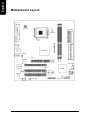
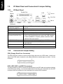
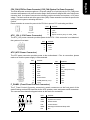
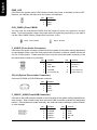
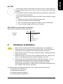
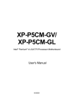
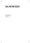
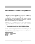
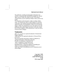
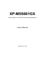
XP-M5S661GX
Intel® Pentium® 4 LGA775 Processor Motherboard
User's Manual
12MM-M5S661GX-1002R
Copyright Declaration
© 2005 Gigatrend Technology Co., Ltd. All rights reserved. No part of this manual may be
reproduced, copied, translated, or transmitted in any form or by any means without express
permission from Gigatrend Technology. Companies and product names mentioned in this
document are trademarks or registered trademarks of their respective owners.
Legal Disclaimer
The information and content of this document is provided "as is", without warranty of any kind,
express or implied, including but not limited to the warranties of merchantability, fitness for a
particular purpose and non-infringement. Gigatrend Technology assumes no responsibility for
errors or omissions in this document or other documents which are referenced by or linked to
this document. The content of this document are subject to change without prior notice.
Gigatrend Technology may make improvements and/or changes in the product described in
this publication at any time and without prior notice. In no event shall Gigatrend Technology be
liable for any special, incidental, indirect or consequential damages of any kind arising out of
or in connection with the use or performance of this document. If you are uncertain about any
installation procedures, please consult a qualified computer technician.
Terms of Use
To avoid unnecessary errors of operation, please consult the user manual prior to hardware
installation. For more up-to-date information, please link to our company website at http://
www.axper.com.tw
Prior to beginning installation procedures, please make sure that your computer turned off and
is connected to a grounded power outlet. If your system is not turned off during installation,
this could result in harm or damage to the motherboard, the components as well as to the
user.
Motherboard
XP-M5S661GX
Motherboard
XP-M5S661GX
Aug. 5, 2005
Aug. 5, 2005
Contents
Motherboard Layout ......................................................................... 4
1. Product Introduction .................................................................. 5
1.1.
1.2.
Feature Summary ............................................................................. 5
I/O Back Panel and Connectors & Jumper Setting ......................... 6
1.2.1. I/O Back Panel ....................................................................................... 6
1.2.2. Connectors & Jumper Setting .............................................................. 6
2.
Hardware Installation ................................................................. 9
2.1.
Installation of a LGA775 Pentium 4 CPU and Fan Sink ................ 10
2.1.1. Installation of a LGA775 CPU ............................................................ 10
2.1.2. Installation of Fan Sink ....................................................................... 11
3.
4.
5.
2.2.
Installation of Memory..................................................................... 12
2.3.
Installation of the Graphics Card ................................................... 12
BIOS Setup ............................................................................ 13
Driver Installation ..................................................................... 13
Installation of SATA RAID Disks ............................................... 14
5.1.
Configuring the System BIOS for the SATA Channel ..................... 14
5.2.
Creating RAID 0 .............................................................................. 14
5.3.
Creating RAID 1 .............................................................................. 15
5.4.
Making the SATA RAID Driver Disk ................................................. 15
5.5.
Loading the SiS 964 Serial ATA Driver ............................................ 15
KB_MS
ATX_12V
COMA
ATX FDD
LPT
CPU_FAN
LAN
SiS 661GX
F_AUDIO
XP-M5S661GX
VGA
LGA 775
R_USB
USB
AUDIO
PCI1
IDE2 IDE1
CLR_CMOS
IT8705AF
PCI2
SiS 964
SATA1
BIOS
PCI3 BATTERY
CODEC
CD_IN
4
SATA0
F_PANEL
SUR_CEN
F_USB1 F_USB2
PWR_LED
SYS_FAN
ICS1883
DDR2
AGP
DDR1
English
Motherboard Layout
English
1.
Product Introduction
The user manual provides steps related to quick installation. If you wish to view complete
", Open User Manual button located on the driver
product information, please select the "
CD or link to our website at http://www.axper.com to received the most up-to-date information.
1.1.
Feature Summary
CPU
Chipset
Memory
Slots
On-Board IDE
On-Board SATA
On-Board Floppy
On-Board Peripherals
On-Board VGA
On-Board LAN
On-Board Sound
BIOS
I/O Control
Hardware Monitor
Form Factor
LGA775 for Intel® Pentium® 4 Processor
Intel® Pentium® 4 533MHz FSB
L2 cache depends on CPU
North Bridge: SiS® 661GX
South Bridge: SiS® 964
2 184-pin DDR DIMM sockets, supports up to 2GB DRAM (Max.)
Supports DDR400/DDR333/DDR266 DIMM
Supports only 2.5V DDR SDRAM
1 AGP slot support 4X/8X(1.5V) device
3 PCI slots support 33MHz & PCI 2.2 compliant
2 IDE controllers provide IDE HDD/CD-ROM(IDE1, IDE2) with PIO,
Bus Master (Ultra DMA33/ATA66/ATA100/ATA133) operation modes
Can connect up to 4 IDE devices
2 SATA ports support 2 SATA devices with up to 150MB/s transfer
rate and can support data striping (RAID 0) and mirroring (RAID 1)
1 Floppy port supports 2 FDD with 360K, 720K,1.2M, 1.44M and
2.88M bytes
1 Parallel port supports Normal/EPP/ECP mode
1 VGA port, 1 Serial port (COMA)
8 USB 2.0/1.1 ports (4 x Rear, 4 x Front by cable)
1 Front Audio connector
1 PS/2 Keyboard
1 PS/2 Mouse
Built-in SiS® 661GX Chipset
Built-in ICS1883 chip
1 RJ45 port
Realtek ALC655 CODEC
Support 2 / 4 / 6 channel
Line Out / Line In / Mic In
CD In connection
Licensed AWARD BIOS
Supports BIOSNow!
IT8705AF
System voltage detect
CPU temperature detect
CPU/System fan revolution detect
Micro-ATX form factor, 24.4cm x 23.0cm
5
English
1.2.
I/O Back Panel and Connectors & Jumper Setting
1.2.1.
I/O Back Panel
PS/2
Mouse
Parallel Port
LAN
Line In
USB
Line Out
Mic In
PS/2
Keyboard
COMA
PS/2 Keyboard
PS/2 Mouse connector
Parallel port (LPT)
COMA (Serial port)
VGA Port
USB
(Universal Serial Bus Port)
LAN (RJ45 LAN Port)
Line In
Line Out
Mic In
1.2.2.
USB
VGA
Connects PS/2 standard keyboard and PS/2 standard
mouse
Connects to printer
Connects to serial-based mouse or data processing devices
Connects to 15-pin D-Sub device such as a monitor
Prior to use, please make sure that your system as well
as the connected attachments support the USB interface.
If driver installation is required, please consult the USB
section of the user manual.
Internet connection with speed of up to10/100Mbps
Connects to optical devices, CD players and other audio
input devices
Connects to speakers or headphones
Connects to microphone
Connectors & Jumper Setting
FDD (Floppy Disk Drive Connector)
The FDD connector is able to connect a single floppy disk drive via a FDD cable. Usually one
edge of the FDD cable is marked in red, please attach this marked edge to position 1 on the
connector.
2
34
1
33
IDE1 / IDE2 (IDE1 and IDE2 Connectors)
The IDE connector is able to connect two IDE devices via an IDE cable and requires checking
of the IDE jumper setting. It is recommended that the hard drive be connected to the first IDE
connector while the optical drive be connected to the second IDE connector.
6
39
1
40
2
The cooler fan power connector supplies a +12V power voltage via a 3-pin/4-pin(only for CPU_FAN) power
connector and possesses a ful-proof connection design. Most coolers are designed with color-coded power
connector wires. A red power connector wire indicates a positive connection and requires a +12V power
voltage. The black connector wire is the ground wire (GND). Please remember to connect the power to the
cooler to prevent system overheating and failure.
Caution!
Please remember to connect the power to the CPU fan to prevent CPU overheating and failure.
PIN
1
1
SYS_FAN
CPU_FAN
ATX_12V (+12V Power Connector)
SIGNAL
1
GND
2
3
+12V
Sense
4
Speed Control (Only for CPU_FAN)
The ATX_12V power connector provides power to the CPU. If this connector is not attached,
the system will not start.
PIN
4
3
2
1
SIGNAL
1
GND
2
3
GND
+12V
4
+12V
ATX (ATX Power Connector)
The ATX power connector provides power to the motherboard. Prior to connection, please
make sure that the power supply is disconnected.
PIN
11
20
1
10
SIGNAL
PIN
SIGNAL
1
2
3.3V
3.3V
11
12
3.3V
-12V
3
GND
13
GND
4
+5V
14
PS_ON (soft on/off)
5
6
GND
+5V
15
16
GND
GND
7
GND
17
GND
8
Power Good
18
-5V
5VSB (stand by +5V)
+12V
19
20
+5V
+5V
9
10
F_PANEL (Front Panel Control Connector)
SPK-
SPK+
MSG+
MSGPW+
PW-
The F_Panel Control Connector connects to certain connectors on the front panel of the
system casing such as IDE Hard Disk Active LED, speaker, reset, and power on/off connectors.
You can use the schematic diagram below as the basis for connection.
20
2
1
HD+
HDRESRES+
NC
19
PIN
HD
SIGNAL
IDE Hard Disk Active LED
SPK
Speaker Connector
RES
Reset Switch
PW
MSG
Power Switch
Message LED/Power/Sleep LED
NC
NC
7
English
CPU_FAN (CPU Fan Power Connector); SYS_FAN (System Fan Power Connector)
English
PWR_LED
Connects to the system power LED indicator whereby the power is indicated as ON or OFF.
However, the indicator will flash when the system is suspended.
PIN
1
1
SIGNAL
MPD+
2
MPD-
3
MPD-
CLR_CMOS (Clear CMOS)
You can clear the motherboard CMOS with the jumper to return your system to its initial
status. To prevent improper usage, the jumper does not include the jumper plug. If you wish to
use the Clear CMOS function, please short circuit the 1-2Pin.
Short : Clear CMOS
Open : Normal
1
1
F_AUDIO (Front Audio Connector)
Connects to the audio connector located on the front panel of the system casing (dependent
on case design). When use of the front panel audio connector is required, please remove the
5-6 pin, 9-10pin jumper. Please note that use of only the front panel audio connector or the
rear panel audio connector is permitted.
PIN
10
2
9
1
SIGNAL
PIN
SIGNAL
1
2
MIC
GND
6
Rear Audio (R)
7
Reserved
3
MIC_BIAS
4
POWER
8
9
NO PIN
Front Audio (L)
5
Front Audio (R)
10
Rear Audio (L)
CD_IN (Optical Drive Audio Connector)
Connects CD-ROM or DVD-ROM audio connector.
PIN
1
SIGNAL
1
CD_L
2
3
GND
GND
4
CD_R
F_USB1/F_USB2 (Front USB Connector)
Connects to the USB connector located on the front panel of the system casing (dependent on
case design). Note: Please make sure that each USB connection matches its designated
position. If connections are made incorrectly, the result can lead to inability to use the function
or even damage.
8
PIN
SIGNAL
1
POWER
PIN
6
SIGNAL
USB Dy+
2
10
2
POWER
7
GND
1
9
3
4
USB DxUSB Dy-
8
GND
5
USB Dx+
9
10
NO PIN
NC
The improper removal of the battery can result in harm. When replacing a
battery, please make sure you use one that is of similar brand and model
number.
For information related to battery specifications and precautions, please refer
to the manufacturer instructions.
If you wish to delete the data stored in the CMOS, please follow the steps
below:
1. Please turn off your computer and unplug the power.
2. Remove the battery from the motherboard.
3. Wait 10 minutes and then replace the battery onto the motherboard.
4. Plug in the power supply and turn on your system.
SUR_CEN (Surround Center Connector)
Connects to the optional surround center cable.
PIN
2.
2
6
1
5
SIGNAL
1
2
SUR OUTL
SUR OUTR
3
GND
4
No Pin
5
6
CENTER_OUT
LEF_OUT
Hardware Installation
1. Please make sure that the CPU used is supported by your motherboard.
2. Please be aware of the placement position of the CPU. If the CPU does not
insert properly, do not apply force but check the placement position.
3. Please make sure that an even layer of heat sink paste is added between the
CPU and the fan sink.
4. Please do not turn on the power prior to installing the fan sink. Doing so can
result in overheating and lead to permanent damage to the CPU.
5. Please follow the CPU specifications when setting the frequency. It is not
recommended that system speed settings exceed that of hardware
specifications. If you wish to set your system speed to exceed the
recommended specifications, please check your hardware specifications eg:
CPU, graphics card, memory, hard drive
The following must be supported to allow the use of Hyper-Threading Technology:
- an Intel Pentium 4 CPU with HT
- a motherboard supporting HT
- HT selection feature within BIOS
- an operating system supporting HT
9
English
BATTERY
English
2.1.
Installation of a LGA775 Pentium 4 CPU and Fan Sink
2.1.1.
Installation of a LGA775 CPU
1. Push the socket lever arm down and away from the
CPU socket and raise it up completely.
2. Open the load plate and gently remove the plastic cover.
3. Hold the CPU with your thumb and index fingers (do not
touch the bottom of the CPU when holding it).
Align notchs on the two sides of the CPU with the small
sockets of the CPU socket and place the CPU straight
down.
4. Make sure the CPU is properly installed and then close
the load plate. Lower the socket lever and engage it to
lock the CPU in place.
10
English
2.1.2.
Installation of Fan Sink
1. Apply a thin coating of thermal paste to complete cover
the surface of the CPU.
2. Align the four fasteners of the fan sink with the four
holes around the CPU socket. Push down each fastener and you should hear a "click" when the fastener is
attached. Make sure the four fasteners are attached
securely.
Prior to installation of the fan sink, check the direction of
each fastener by the arrow engraved on fastener top.
Before attaching the fasteners, turn each fastener
clockwise. To uninstall the fan sink, release each fastener by rotating the fastener along the direction of the
arrows and pull them up.
3. Connect the 4-wire power cable of the fan sink to the
CPU_FAN header on the motherboard to complete the
installation.
11
English
2.2.
Installation of Memory
1. Before installing or removing memory, please make sure that the computer power
is turned off to prevent hardware damage.
2. Please make sure that the memory used is supported by the motherboard.
3. Memory modules have a foolproof insertion design. The memory can be
installed only when facing the correct position. If you cannot insert the module,
please switch directions.
4. It is recommended that memory of similar capacity, specifications and brand be
used.
The motherboard supports DIMM memory modules, whereby BIOS will automatically detect
memory capacity and specifications. Memory modules are designed so that they can be
inserted only in one direction.
1. Unfasten the clips on each end of the memory slots.
Correctly align the memory module in the slot and
push downwards.
2. Once the memory module is correctly inserted, the
clips will automatically refasten. If the memory
module is positioned in the wrong direction, it will
not insert. If this occurs, please switch directions.
2.3.
Installation of the Graphics Card
1. Before installing the graphics card, please carefully read the accompanying user manual.
As well, make sure the computer power is turned off.
2. Your graphics card must be 1.5V and support the AGP4X/8X specification.
3. When installing or removing the graphics card, first pull out the white AGP knob before
insertion or removal. Releasing the AGP knob will hold the graphics card firmly in place.
12
English
3.
BIOS Setup
BIOS (Basic Input and Output System) stores all the information of the motherboard settings
that is needed for system initiation as well as examining the CMOS. Its CMOS SETUP utility
allows the user to make changes in BIOS configurations that are required or to activate
certain features.
The CMOS SETUP saves each item configuration in the CMOS SRAM of the motherboard.
When the power is turned off, the battery on the motherboard supplies the required power
to the CMOS SRAM.
When the power is turned on, pushing the <Del> button during the BIOS POST (Power-On
Self Test) will bring up the CMOS SETUP screen. If you wish to enter the BIOS setup, please
press "Ctrl + F1" at the BIOS setup screen.
When using BIOS setup for the first time, it is recommended that you save the present BIOS
onto a disk in case you need to reset the BIOS back to its original settings. If you wish to
update to a new BIOS, the BIOSNow! can be used.
The user can select BIOSNow! as a way to quickly and easily update or back up BIOS
without entering the operating system.
4.
Driver Installation
Driver installation for the Windows 2000/XP operating systems is simple. Once you insert
the provided driver disks into your optical drive, the AUTORUN screen will appear. If this
screen does not appear, you can use "D:\setup.exe" (with "D" being the specified drive) to
bring up the screen shown below. Just follow the screen instructions to easily complete
driver installation.
13
English
5.
Installation of SATA RAID Disks
The Serial ATA channel controlled by the SiS 964 southbridge chip supports RAID 0 and
RAID 1. This section explains the steps required to configure RAID disks.
RAID (Redundant Array of Independent Disks) is a method of combining two hard disk
drives into one logical unit. The advantage of an Array is to provide better performance
or data fault tolerance. Hard disk drives can be combined together through a few
different methods. The different methods are referred to as different RAID levels. Different RAID levels represent different performance levels, security levels and implementation costs.
RAID 0 (Striping)
RAID 0 reads and writes sectors of data interleaved between multiple drives. If any disk
member fails, it affects the entire array. The disk array data capacity is equal to the
number of drive members times the capacity of the smallest member. RAID 0 does not
provide fault tolerance funtionality.
RAID 1 (Mirroring)
RAID 1 writes duplicate data onto a pair of drives and reads both sets of data in parallel.
If one of the mirrored drives suffers a mechanical failure or does not respond, the
remaining drive will continue to function. Due to redundancy, the drive capacity of the
array is the capacity of the smallest drive. Due to the fault tolerance, if any RAID 1 drive
fails, data access will not be affected as long as there are other working drives in the
array.
5.1.
Configuring the System BIOS for the SATA Channel
1. Connect two SATA hard disks to the SATA ports on the motherboard.
2. Reboot you system and press the <Delete> key to enter the BIOS setup screen after
POST begins.
3. Under Integrated Peripherals, locate the SATA controller and SATA mode setup
options. Assure that the SATA controller and SATA RAID mode are enabled.
4. Save changes and exit the BIOS Setup.
5.2.
Creating RAID 0
1. Upon re-boot, you will see the RAID software prompting you to press CTRL+S keys to
enter the SiS RAID BIOS Setting Utility. Press CTRL+S.
2. In the SiS RAID BIOS Setting Utility, press <R> to enter the RAID Setup utility.
3. In the RAID Setup window, press <A> to create RAID volume. Then, use number keys
1~3 to select a RAID type. Press 2 to select RAID 0 and then press <Enter>.
4. Use <1> or <2> key to select Auto Create or Manual Create.
5. When the next message appears, if you wish to proceed to map and stripe all current
data and future data to the RAID disks, press <Y>. Or press <N> to perform striping on
future data only. Then press <Enter>.
6. After the completion, you will see the RAID 0 array under the Current Created Raid
list in the RAID Setup window.
14
Creating RAID 1
5.4.
Making the SATA RAID Driver Disk
For the RAID disks to be recognized correctly during Windows Setup process, you need
to install the SiS 964 SATA RAID driver at the beginning of Windows Setup. The procedure below introduces how to make a floppy disk containing the RAID driver.
1. Insert the Axper motherboard driver CD to the CD-ROM drive in your system. Go to
My Computer and right-click the CD-ROM icon to select Open.
2. In the BootDrv folder, double-click the Menu.exe file. Then a MS-DOS prompt screen
will appear, presenting a list of SATA/RAID/SCSI controllers.
3. Select the RAID controller for your motherboard. (Example: select SiS 964 SATA for
the XP-M5S661GX motherboard.) Then the driver file will be automatically copied and
transferred to the floppy disk. Wait until it's done, then you can begin to install
Windows operating system to the RAID disks.
5.5.
Loading the SiS 964 Serial ATA Driver
1. Boot from the Windows Installation CD. Press <F6> as soon as you see the Press F6
if you need to install a 3rd party SCSI or RAID driver message. Follow the onscreen instructions and supply the RAID driver with the floppy disk. Then proceed to
complete the Windows installation and drivers installation.
(Note: Each time you add a new hard drive to a RAID array, the RAID driver will have to
be installed under Windows once for that hard drive. After that, the driver will not have
to be installed.)
For more details about SATA RAID configurations, please refer to the manual file in the motherboard
driver CD.
This product must not be disposed of with your other household waste and must be
handed over to a designated collection point for the recycling of waste electrical and
electronic equipment !
15
English
5.3.
1. Upon re-boot, you will see the RAID software prompting you to press CTRL+S keys to
enter the SiS RAID BIOS Setting Utility. Press CTRL+S.
2. In the SiS RAID BIOS Setting Utility, press <R> to enter the RAID Setup utility.
3. In the RAID Setup window, press <A> to create RAID volume. Then, use number keys
1~3 to select a RAID type. Press 3 to select RAID 1 and then press <Enter>
4. Use <1> or <2> key to select Auto Create or Manual Create.
Manual Create allows you to assign the source disk.
5. W hen the prompt "Duplicate the SOURCE data to RAID disks?" appears, press Y or N
as needed.
6. After the completion, you will see the RAID 1 array under the Current Created Raid
list in the RAID Setup window.
16
English