1
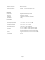
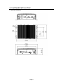
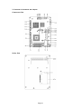
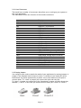
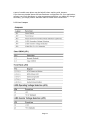
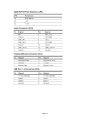
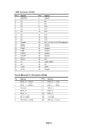
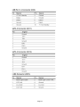
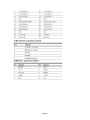
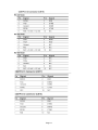
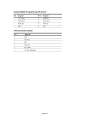
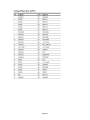
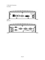
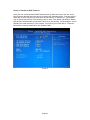
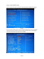
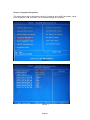
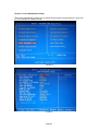
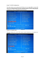
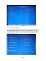
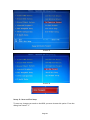
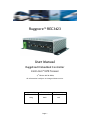
Ruggcore™ REC3423
User Manual
Ruggdized Embedded Controller
Intel® Atom™ N270 Processor
(1st Edition 09/30/2009)
All information is subject to change without notice.
Approved by
Checked by
Prepared by
Ming
Hank
Jack
Page 1
RECORD OF REVISION
Version and Date
Sep.30 2009
Page
Old Description
all
New Description
Preliminary Release
Page 2
Remark
Acknowledgments
All other products’ name or trademarks are properties of their respective owners.
Award is a trademark of Award Software International, Inc.
®
®
Intel , Atom™ are trademarks of Intel Corporation.
®
Microsoft Windows is a registered trademark of Microsoft Corp.
IBM, PC/AT, PS/2, and VGA are trademarks of International Business Machines
Corporation.
Please be notified that all other products’ name or trademarks not be mentioned
above are properties of their respective owners.
Page 3
Packing List
Before installation, please ensure the following items have been shipped:
z
1 x REC3423 Embedded Controller
z
1 x CD-ROM for manual (in PDF format) and drivers
If any of these items should be missing or damaged, please contact your distributor
or sales representative immediately.
Ordering Information
Model Number Description
REC3423-A01
Intel Atom™ N270 CPU, Fanless, DC 8.5~19V input, SODIMM DDRII 1GB RAM, 2 x
GbE, 4 x COM, 1 x DVI-I, 2 x USB2.0, CompactFlash™, Mini-PCI, HDD Bay
Optional Accessories
810218001020 DVI-I to DVI-D & DVI-I to VGA Port Y Cable
810618301015 Power Cable USA Type
810618301070 Power Cable Europe Type
Page 4
Safety & Warranty
1. Read these safety instructions carefully.
2. Keep this user's manual for later reference.
3. Disconnect this equipment from any AC outlet before cleaning. Do not use liquid
or spray detergents for cleaning. Use a damp cloth.
4. For pluggable equipment, the power outlet must be installed near the equipment
and must be easily accessible.
5. Keep this equipment away from humidity.
6. Put this equipment on a firm surface during installation. Dropping it or letting it
fall could cause damage.
7. Make sure the voltage of the power source is correct before connecting the
equipment to the power outlet.
8. Position the power cord so that people cannot step on it. Do not place anything
over the power cord.
9. All cautions and warnings on the equipment should be noted.
10. If the equipment is not used for a long time, disconnect it from the power source
to avoid damage by transient over-voltage.
11. Never pour any liquid into an opening. This could cause fire or electrical shock.
12. Never open the equipment. For safety reasons, only qualified service personnel
should open the equipment.
13. If any of the following situations arises, get the equipment checked by service
personnel:
a. The power cord or plug is damaged.
b. Liquid has penetrated into the equipment.
c. The equipment has been exposed to moisture.
d. The equipment does not work well, or you cannot get it to work according to
the user’s manual.
e. The equipment has been dropped and damaged.
f. The equipment has obvious signs of breakage.
14. DO NOT LEAVE THIS EQUIPMENT IN AN ENVIRONMENT WHERE THE STORAGE
TEMPERATURE IS BELOW -20°C (-4°F) OR ABOVE 70°C (158°F). IT MAY DAMAGE THE
EQUIPMENT.
FCC Safety
This device complies with Part 15 FCC Rules.
Operation is subject to the following two conditions:
(1) this device may not cause harmful interference, and
(2) this device must accept any interference received including
interference that may cause undesired operation.
Page 5
TABLE OF CONTENT
RECORD OF REVISION ........................................................................................................ 2
1.0 INTRODUCTION......................................................................................................... 7
2.0 HARDWARE INSTALLATION ........................................................................................... 9
3.0 AWARD BIOS SETUP.................................................................................................... 21
4.0 DRIVER INSTALLATION................................................................................................ 32
Page 6
1.0 INTRODUCTION
1.1 About Ruggcore™ Embedded Controller
The REC3423 Embedded Controller system’s design concept not only focuses on the fast
expanding Machine Automation market but also the Industrial Automation industry. The
REC3423 provide one mini PCI slot (internal) for expansion.
A solid sealed aluminum case provides vibration and dust resistance while also providing
a passive cooling solution. The REC3423 provides system integrators with a turn-key
solution and versatile application development path to fulfill the diversified market
demand.
The REC3423 can be used as a standalone system, and wall-mounted. The system
accepts a wide range of power supplies (DC power in). The rugged aluminum case not
only provides great protection from EMI, shock/vibration, cold and heat, but also passive
cooling for quiet fanless operation.
The REC3423 Embedded Computer supports Compact Flash card for storage options and
it can provide the diversified application field. Therefore REC3423’s expandable
function, compact size combined with fanless design and highly efficient heat
conduction mechanism can fulfill any rugged technical application in industrial
automation, factory control, and test instrumentation.
1.2 FEATURES
z
z
z
z
Intel® Atom Based Fanless Design
Rugged Design
Rich IO (4 USB, 2 COM, 2 GbE)
Wide Range DC Input (+8.5V ~ 19V)
1.3 SPECIFICATIONS:
System
Processor
Intel Atom N270 Processor
Chip Set
Intel945GSE + ICH-7M
System Memory
DDRII SODIMM x 1, Max. 2GB (DDRII 400/533)
Ethernet
Intel 82574L GbE (Gigabit Ethernet)
Storage
CF Card
SATAII HDD Bay
Audio
Line-Out, MIC in
I/O Interface-Front
PWR/HDD LED, DC-In, Power on SW,
RJ45 x2, USB x2, COMx1, DVI-I x1, CFD
I/O Interface-Rear
Audio Phone Jack (Line-out, MIC-in), USBx2, COMx3
(RS232 x2, RS232/422/485 x1), DC Input Phoenix Connector
BIOS
Award
Watchdog Timer
Generates a time-out system reset
Page 7
Expansion Interface
Mini PCI (internal)
Power Requirement
+8.5V DC ~ +19V DC wide range DC input
Mechanical
Construction
Rugged Aluminum Alloy chassis
Mounting
Wallmount, Desktop
Dimension
196mm (W) x 69mm(H) x 150mm(D)
Net Weight
2.3Kg
Environment
Operating Temperature
-15°C ~ 50°C ( 5°F ~ 131°F) – HDD
Storage Temperature
-20°C ~ 70°C (-4°F ~-158°F)
Operating Humidity
5~90% @ 40°C, non-condensing
Vibration:
5g rms / 5~500Hz / random operation (CFD);
1g rms / 5~500Hz / random operation (HDD);
Shock:
50g peak acceleration (11msec. duration)(CFD)
20g peak acceleration (11msec. duration) (HDD)
Certification
CE/FCC
Page 8
2.0 HARDWARE INSTALLATION
2.1 REC3423 Dimension
Page 9
2.2 Location of Connectors and Jumpers
Component Side
Solder Side
Page 10
2.2.1 List of Connectors
The board has a number of connectors that allow you to configure your system to
suit your application.
The table below shows the function of the board's connectors:
Location
CN1
CN3
CN4
CN9
CN11
CN12
CN12
CN13
CN14
CN15
CN16
CN17
CN18
CN19
CN20
CN21
CN22
CN23
CN24
CN25
CN26
CFD1
MPCI1
DIMM1
Function
Audio Connector
Keyboard / Mouse Connector
USB Port 1,2 Connector
USB Port 3,4 Connector
SATA 1 Connector
SATA 2 Connector
I2C Connector
LVDS Connector
LVDS Inverter Connector
COM Port 1 Connector
COM Port 2 Connector
COM Port 3 Connector
COM Port 4 Connector
DVI Display Connector
Digital I/O Connector
Onboard BIOS Programming I/F
ATX Connector
Wide Range Voltage Input Connector
+5V Power Input Connector
CPU Fan Connector
+5V / +12V Output Connector
Compact Flash Disk
Mini-PCI Slot
DDRII SODIMM Slot
2.2.2 Setting Jumpers
You configure your card to match the needs of your application by setting jumpers. A
jumper is the simplest kind of electric switch. It consists of two metal pins and a
small metal clip (often protected by a plastic cover) that slides over the pins to
connect them. To “close” a jumper you connect the pins with the clip.
To “open” a jumper you remove the clip. Sometimes a jumper will have three pins,
labeled 1, 2 and 3. In this case you would connect either pins 1 and 2 or 2 and 3.
Page 11
A pair of needle-nose pliers may be helpful when working with jumpers.
If you have any doubts about the best hardware configuration for your application,
contact your local distributor or sales representative before you make any change.
Generally, you simply need a standard cable to make most connections.
2.2.3 List of Jumpers
Page 12
Page 13
Page 14
Page 15
Page 16
Page 17
Page 18
Page 19
2.3 External I/O Connectors
Front View
Rear View
Page 20
3.0 AWARD BIOS SETUP
3.1 Award BIOS Setup
The BIOS setup, also called CMOS setup, is a crucial part of the proper setting up of
Ruggcore. The BIOS (Basic Input Output System) tells the operating system the
characteristics of the main basic components of Ruggcore. Because of this, an
incorrectly set up BIOS can result in some devices not being recognized by the
operating system.
Getting into the Award BIOS
Cold boot Ruggcore and when you see the first screen showing in monitor, press the
Delete key repeatedly till you get a blue screen titled.
When you successfully get into the BIOS setup, you will be presented with the
following menu.
Setup 1: The Main BIOS Menu.
The sections that follow provide guidelines on how to set up the various settings in
each section of the BIOS. We have concentrated only on those settings that may
need changing, if a setting does not appear in this document, leave it as you found
it.
Press Enter on a main menu option to go into that section.
To return to the Main Menu from within a section, press Escape.
Screen 1
Page 21
Setup 2: Standard CMOS Features
Here you can setup the basic BIOS features such as date and time. Use the arrow
keys to move around and press enter to select the required option. You can specify
what IDE or SATA devices you have such as Hard drive, CF device etc. The easiest
way to setup the devices is by leaving it set to auto. This allows the BIOS to detect
the devices automatically so you don't have to do it manually. At the bottom, it also
displays the total memory in your system. Verify that your hard disk or CF device
have been correctly detected in the shaded fields.
Screen 2
Page 22
Setup 3: Advanced BIOS Features
As you can see from screen 3, there are numerous advance settings which you can
select if required. For most cases leaving the default setting should be adequate.
Screen 3
As you can see from the screen 4, the first and second boot device is set to Hard Disk.
This ensures that the hard disk is read first when the system boots, and therefore
can boot from boot disk. The third is set to CD ROM.
Screen 4
Page 23
Setup 4: Advanced Chipset Features
Here you can setup the contents of the chipset buffers. It is closely related to the
hardware and is therefore recommended that you leave the default setting unless
you know what you are doing. Having an incorrect setting can make your system
unstable.
Screen 5
Page 24
Setup 5: Integrated Peripherals
This menu allows you to change the various I/O devices such as IDE controllers, serial
ports, keyboard, USB, and LAN. You can make changes as necessary.
Screen 6
Screen 7
Page 25
Setup 6: Power Management Setup
The power management allows you to setup various power saving features, when the
PC is in standby or suspend mode.
Screen 8
Screen 9
Page 26
Setup 7: PnP/PCI Configurations
This menu allows you to configure your PCI slots. You can assign IRQ's for various PCI
slots. It is recommended that you leave the default settings, BIOS can automatically
configure all the boot and plug & play compatible devices. You may choose manual
mode when you want to change PCI device resources.
Screen 10
Setup 8: PC Health Status
This menu displays the current CPU, chipset, system temperature, fan speeds, and
voltages.
Screen 11
Page 27
Screen 12
Setup 9: Load Fail-Safe Defaults
If you made changes to the BIOS and your system becomes unstable as a result, you
can change it back to default. However if you made many changes and don't know
which one is causing the problem, your best bet is to choose the option "Load Fail
Safe Defaults" from the BIOS menu. This uses a minimal performance setting, but the
system would run in a stable way. From the dialog box Choose "Y" followed by enter
to load Fail-Safe Defaults.
Screen 13
Page 28
Setup 10: Load Optimized Defaults
Like the Fail-Safe mode above, this option loads the BIOS default settings, but runs
the system at optimal performance. From the dialog box Choose "Y" followed by
enter to load Optimized Defaults.
Screen 14
Steup11: Set Password
There are two kinds of password protect your BIOS, Supervisor and User password,
you can specify a password and make sure you don't forget the password. You will be
asked for password when you into BIOS setup manual.
Page 29
Screen 15
Screen 16
Setup 12: Save and Exit Setup
To save any changes you made to the BIOS you must choose this option. From the
dialog box choose "Y".
Page 30
Screen 17
Setup 13: Exit without Saving
If you don't want to save changes made to the BIOS, choose "N" from the dialog box.
Screen 18
Page 31
4.0 DRIVER INSTALLATION
The REC3423 comes with a CD-ROM that contains all drivers and utilities that meet
your needs.
Follow the sequence below to install the drivers:
Step 1 – Install INF Driver
Step 2 – Install VGA Driver
Step 3 – Install LAN Driver
Step 4 – Install Audio Driver
USB 2.0 Drivers are available for download using Windows Update for both Windows
XP and Windows 2000. For additional information regarding USB 2.0 support in
Windows XP and Windows 2000, please visit www.microsoft.com/hwdev/usb/.
Please read instructions below for further detailed installations.
4.1 Installation:
Insert the REC3423 CD-ROM into the CD-ROM Drive. And install the drivers from Step
1 to Step 5 in order.
Step 1 – Install Chip Driver
1. Click on the Step 1 - INF Update Utility v8.2.0.1014 folder and double click
on the Setup.exe
2. Follow the instructions that the window shows
3. The system will help you install the driver automatically
Step 2 – Install VGA Driver
1. Click on the Step 2 - Intel Graphics Media Accelerator Driver folder and
select the OS folder your system is
2. Double click on the Setup.exe file located in each OS folder
3. Follow the instructions that the window shows
4. The system will help you install the driver automatically
Step 3 –Install LAN Driver
1. Click on the Step 3 - Intel Ethernet Driver folder and select the OS folder
your system is
2. Double click on the .exe file located in each OS folder
3. Follow the instructions that the window shows
4. The system will help you install the driver automatically
Step 4 –Install Audio Driver
1. Click on the Step 4 - Realtek ALC655 Audio Driver v3.71 folder and select
the OS folder your system is
2. Double click on setup.exe file located in each OS folder
3. Follow the instructions that the window shows
4. The system will help you install the driver automatically
Page 32