1
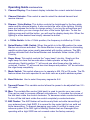
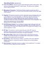
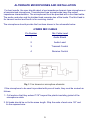
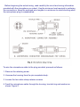
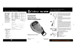
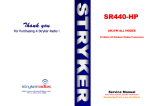
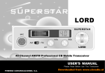
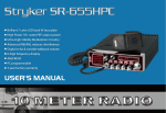
SR-447HPC
AM/FM/PA
10 Meter HF Amateur Mobile Transceiver
USER’S MANUAL
READ THIS MANUAL BEFORE OPERATION
Downloaded from www.cbradio.nl
INTRODUCTION
Congratulations on your purchase of a Stryker 10 meter mobile amateur transceiver.
Your Stryker is designed to provide years of enjoyment and trouble-free service. There
are many features and functions designed into this transceiver. To ensure that your
investment is enjoyed to its fullest extent, please take a few moments and thoroughly
read this manual.
LIMITED WARRANTY
Stryker Amateur Radio warrants this product to be free of defects for a period of one
(1) year from the original date of purchase. You must activate your warranty by
completing the included form or online at www.strykerradios.com/register.aspx
This warranty is non-transferable. This limited warranty is subject to repair or
replacement of defective components only. This warranty is void if the radio has been
tampered with or misused. If your Stryker Radios needs repair any time during the
(1) year warranty period please visit our website: www.StrykerRadios.com to obtain an
RA number or call 910-221-1086 between the hours of 10 a.m. – 5 p.m. Eastern
standard time. If you do need service after your warranty has expired you can still
send your radio to us for repair. Our rates are very reasonable and you can rest
assured that your radio will be fixed correctly.
IMPORTANT: RETAIN YOUR SALES RECEIPT
You will need to include a copy of your original sales receipt along with your radio
when sending it in for warranty repair.
INSTALLATION
1. Contents
Unpack and inspect your Stryker SR-447/497 for missing or damaged
Components.
Quantity
Description
1
1
1
1
1
Stryker SR-447/497 Transceiver
Microphone
DC Power Cord with Inline Fuse
Mounting Bracket with Hardware
Microphone Hanger with Hardware Set
1
INSTALLATION CONTINUATION
Location
Plan the location of the transceiver and microphone brackets before starting the
installation. Select a location that is convenient for operation and does not interfere
with the driver or passengers in the vehicle. In automobiles, the transceiver is usually
mounted below the dash panel, with the microphone bracket beside it.
Mounting
Your mobile radio is supplied with a universal mounting bracket. When mounting the
bracket and radio to your car, make sure it is mechanically strong. Also provide a good
electrical connection to the chassis of the vehicle. Proceed as follows to mount the
transceiver:
Mount the Transceiver
After you have determined the most convenient location in your vehicle, hold the mobile radio with the mounting bracket in the exact location desired. If nothing will
Interfere with mounting it in the desired position, remove the thumbscrews and use the
mounting bracket as a template to mark the holes for the mounting screws. Before
drilling the holes, make sure nothing behind the surface will be damaged or interfere
with the installation.
Electrical Connections
The Stryker SR447/497 is designed to work on any 13.8 volt DC, negative ground
electrical source. The condition of a vehicle’s electrical system can have a profound
affect on the performance of the radio. A low battery, worn generator/alternator, or
poor voltage regulator will seriously impair the performance of the transceiver. Any of
the above conditions could result in a high level of receiver noise generation or a
Substantial loss of the transmitter’s RF output. Make sure that all these components
on your vehicle’s electrical system are in good condition prior to installing the
transceiver.
CAUTION! VOLTAGE EXCEEDING 15 Volts DC WILL DAMAGE THE RADIO.
MEASURE VOLTAGE AT BATTERY TERMINALS, WITH VEHICLE RUNNING,
PRIOR TO INSTALLATION!
1. Before making any electrical connections make sure the volume (VOL) control is in
the“OFF” position.
2. Connect the positive (+) red wire of the DC power cord to a positive 13.8-volt
source at the vehicle fuse block. If connecting to the fuse block, it is recommended
that a switched power source be used so that the power to the
Transceiver is disconnected when the vehicle is off. This eliminates the possibility
the transceiver draining the vehicle’s battery.
3. Connect the negative (-) black wire to a metal part of the vehicle’s frame, or
chassis ground. Make sure that this is a good ground connection.
Antenna Connections
The Stryker SR447/497 has a jack in the rear for a standard PL-259 antenna plug. If
you are looking for the most range for your transmission, use a vertically polarized,
quarter-wave length antenna. If antenna height is a problem, you may use a shorter,
loaded-type whip antenna although you can expect some loss of transmission range.
Your antenna should always be adjusted for the lowest possible SWR (1.5 or less.)
To adjust your antenna for best performance you must use a SWR meter, these can be
purchased separately for at little as $12.95 from various retailers. Failure to properly
adjust your antenna(s) will diminish your operational range and could result in damage
to your radio. Damage that results from operating with high SWRs is not
covered under your factory warranty!
Tuning the Antenna for Optimum SWR
Because such a wide variety of base and mobile antennas are available, this section
will concern itself only with the usual types of mobile adjustable antennas.
Antenna length is directly related to signal frequency. Therefore, it must be
tuned to resonate optimally throughout the frequency range of the transceiver.
Lower frequencies require a longer antenna than higher frequencies.
Due to the various methods of adjusting antennas for proper SWR, we have
chosen what we think is the optimum method:
A. Antennas with adjustable screws (setscrews).
1. Start with the antenna extended and tighten the setscrew lightly enough so
that the antenna can be lightly tapped with your finger for easy adjustment.
2. Set your Stryker radio to your desired operating frequency or the center of
the range of frequencies you plan to use. Press the PTT (Press-To-Talk) switch,
and tap the antenna (making it shorter). The SWR meter will show a lower reading
each time the antenna is tapped. By continuing to shorten the antenna, you will
notice the SWR reading will reach a low point and then start rising again.
This means that you have passed the optimum point for the middle frequency.
3. Extend the antenna a short distance and again follow the procedure above.
4. When the lowest point has been reached, switch to the lowest frequency you plan to
operate on and then to the highest and compare SWR readings. They should be
almost equal.
B. Antennas that must be cut to proper length.
1. Follow the procedure as in A above, but adjust the length
by cutting in 1∕8" increments until a good match is obtained.
2. Be very careful not to cut too much off the antenna at one time.
Once it is cut, it can no longer be lengthened.
3
Tuning the Antenna for Optimum SWR CONTINUATION
3. The whip is easily cut by filing a notch all the way around,
then breaking the piece off with pliers.
NOTE
The proper setting is achieved when the SWR is 1.5 or below and when it has
the same reading for the low and high frequencies in the range you plan to use.
External Speaker
The external speaker jack (EXT) on the rear panel is used for remote receiver
monitoring. The external speaker should have 8 ohms impedance and be able to
handle at least four watts. When the external speaker is plugged in, the internal
speaker is disabled.
Public Address
To use the transceiver as a public address system, connect an external 8 ohm speaker
that is able to handle at least four watts to the PA jack on the rear panel. Direct the
speaker away from the microphone to prevent acoustic feedback. Physical separation
or isolation of the microphone and speaker is important when operating the PA at high
output levels.
Improper Radio Adjustments
Service by unqualified technicians could result in damage to your radio. Never allow
anyone to disable your radio’s modulation limiting circuitry. We have designed your
radio for optimal performance and durability. Disabling this circuitry could damage
your radio and potentially void your factory warranty!
For further service information please visit www.StrykerRadios.com
Operating Guide CONTINUATION
1. Channel Display: The channel display indicates the current selected channel
2. Channel Selector: This control is used to select the desired transmit and
receive channel.
3. Dimmer / Color Button: This button controls the brightness for the face plate,
meter and the channel display. It also controls the color of the lighting. Quickly
press and release the button to change colors, if you key the microphone and
press the button you can change the color of the meter light also. To dim the
lighting press and hold the button, you will see the display slowly dim. When the
lighting is at the desired level simply release the button.
4. + 10Khz Switch: In the +10kHz position, the frequency is shifted up 10 kHz.
5. Noise Blanker / ANL Switch: When this switch is in the NB position the noise
Blanker circuits are activated. The Noise Blanker is very effective in eliminating
repetitive pulse type noise usually associated with ignition systems. The NB+
position activates both the Noise Blanker and Automatic Noise Limiter (ANL)
Circuitry.
6. Roger Beep: This switch controls the "roger beep" circuitry. Simply put the
roger beep is a tone that sounds when a radio operator un-keys their
microphone. Switch position "1" will sound one short beep when the radio is
un-keyed. Position "2" will sound two short beeps and position "off" de-activates
the roger beep completely.
7. Mode Switch: This switch allows you to operate in AM, FM or PA mode. The PA
feature allows the radio operator to use their radio as a public address system.
8. Band Selector: Use to select frequency segments A-H.
9. Transmit Power: This variable control allows the power to be adjusted from 2.5 60+ watts.
10. Mon: The variable Mon control (talk back) is used to monitor your own voice.
This can be used to compare different microphones. To increase the volume of
the talk back rotate the control clockwise. To decrease rotate counterclockwise.
To turn off the talk back rotate the control completely counterclockwise.
11. AWI Flasher: The AWI flasher will continuously flash red while transmitting if
your antenna has a high SWR. It is normal for the meter light to turn solid red
while transmitting. To prevent damaging your radio it’s critical to repair your
antenna system if the AWI light is flashing! Radios that are Damaged from
operating with a high SWR are not covered under the factory warranty.
5
Operating Guide CONTINUATION
12. Front Panel Meter: Indicates receive signal strength and RF output power. The
top bar on the meter indicates RF output power. The bottom bar indicates
receive signal strength.
13. Microphone Connector: This Stryker Radio accepts microphones with a
female 4 pin connector. For further wiring information please see the next page
of this manual.
14. Squelch: This control is used to cut off or eliminate receiver background noise
in the absence of an incoming signal. For maximum receiver sensitivity it is
desired that the control be adjusted only to the point where the receiver
background noise or ambient backgrounds noise is eliminated. Turn fully
counterclockwise then slowly clockwise until the receiver noise disappears. Any
signal to be received must now be slightly
stronger than the average received noise.
15. On/Off Volume Control: Turn clockwise to apply power to the unit and to set
the desired listening level. During normal operation, the VOLUME control is
used to adjust the output level obtained either at the transceiver speaker or the
external speaker, if used.
16. RF Gain: This control is used to reduce the gain of the RF (receive)
amplifier under strong signal conditions. For maximum receiver sensitivity
this control should be turn all the way to the right (clockwise)
17. Microphone Gain: Adjusts the microphone gain in the transmit and PA
modes. This controls the gain to the extent that full talk power is available
several inches away from the microphone.
18. Echo Delay: Varies the amount of delay, or duration of the echo repetition.
Rotate clockwise to increase the amount of delay and counterclockwise
to decrease.
19. Echo Volume: Varies the volume or number of echo repetitions. To increase
the echo volume, rotate the control clockwise.
OPERATION GUIDE
For detailed descriptions of all function please see pages 5 & 6
1
LED Channel Display
2
Channel Selector
3
Dimmer / Color Button
4
+10Khz Switch
5
Noise Blanker & ANL
6
Roger Beep
7
AM/FM & PA (Mode)
8
9
8
Band Selector
6
5
18
19
9
10
RF Power Output Control
7
1
4
10 Monitor (Talkback)
11 AWI Flasher
12 Signal Strength Meter
13 Microphone Connector
14 Squelch Control
15 On/Off Volume Control
16 RF Gain
17 Microphone Gain
18 Echo Delay
19 Echo Volume - On/Off
13
12
11
14
15
16 17
3
2
ALTERNATE MICROPHONES AND INSTALLATION
For best results, the user should select a low-impedance dynamic type microphone or
a transistorized microphone. Transistorized type microphones have low output
impedance characteristics. The microphones must be provided with a four-lead cable.
The audio conductor and its shielded lead comprise two of the leads. The third lead is
for transmit control and fourth is for receiving control.
The microphone should provide the functions shown in the schematic below.
4 WIRE MIC CABLE
Pin Number
Mic Cable Lead
1
Audio Shield
2
Audio Lead
3
Transmit Control
4
Receive Control
If the microphone to be used is provided with pre-cut leads, they must be revised as
follows.
1. Cut leads so that they extend 7/16" beyond the plastic insulating jacket of the
microphone cable.
2. All leads should be cut to the same length. Strip the ends of each wire 1/8" and
tin the exposed wire.
9
Before beginning the actual wiring, read carefully the circuit and wiring information
provided with the microphone you select. Use the minimum heat required in soldering
the connections. Keep the exposed wire lengths to a minimum to avoid shorting when
the microphone plug is reassembled.
To wire the microphone cable to the plug provided, proceed as follows:
1. Remove the retaining screw.
2. Unscrew the housing from the pin receptacle body.
3. Loosen the two cable clamp retainer screws.
4. Feed the microphone cable through the housing, knurled ring and washer as
shown Figure 2.
http://www.StrykerRadios.com
PH: 1-910-221-1086
Stryker
Warranty Registration
To validate your one (1) year factory warranty
please register online at:
http://www.strykerradios.com/register.aspx
or fill out the information below and return the original,
or white copy, by mail or fax with a copy of the original
sales receipt to the address below.
Stryker must receive the warranty registration within
30 days of the date of purchase.
Stryker Radios
439 Westwood Shopping Center STE 108
Fayetteville, NC 28314
TEL: 910-221-1086
FAX: 480-247-5927
Registered Owner Information:
First Name
Last Name
Address 1
Address 2
City / Town
Country
Telephone
State / Province
Email
Serial Number
Store
Label Information:
Store Name
Date Purchased
Our goal at Stryker is to provide you, our customer,
with the best possible products and services. One way to do
this is by offering the option of extending the factory warranty
on your product. The extended service contracts offer the
same excellent coverage and service as the provided one (1)
year warranty, only the length of coverage is increased.
The Stryker Extended Service Contracts are only offered at
time of purchase to the original owner and are purchased
direct from Stryker, not a third-party provider. This means your
Stryker product will be serviced by the engineers and
technicians that
designed it. The extended service contracts are optional
and in no way effect your one (1) year factory warranty
that is included with this product!
There are two levels of coverage available. The 1 Year
Extended Service Contract provides an additional one (1)
year of warranty coverage for a total warranty of two (2) years
from the original date of purchase. The 2 Year Extended
Service Contract provides an additional two (2) years of
warranty coverage for a total warranty of three (3) years from
the original date of purchase.
Just as with the provided factory warranty, extended service
contracts are non-transferable and are limited to repair or
replacement of defective components only. All warranties are
void if the radio has been tampered with or misused.
Please select one of the following options:
Postal Code
Product Information:
Product Model (Name)
Special One-Time Offer
Extend Your Factory Warranty to 2 or 3 Full Years
City and State of Store Location
Purchase Price
Limited Warranty
Stryker warrants that this product is free from defects in
materials and workmanship under normal use and conditions
for a period of one (1) year from the date of original
purchase. This warranty is limited to the original purchaser of
the product and is not transferable.
Should service be required by reason of any defect or
malfunctioning the warranty period. Stryker will repair this
product during the 1 year period provided that the defective
unit is returned to Stryker freight prepaid.
This warranty does not cover damage which results from
modification, accident, misuse, abuse, fire, flood, lightning or
other acts of nature or damage resulting from repairs or
alterations performed other than by Stryker.
This warranty gives you specific legal rights, and you may
also have other rights which vary from state to state.
No thank you, I do not require an Extended Service Contract
Contract.
Yes, I would like to purchase the 1 Year Extended
Service Contract for a one time charge of only $59.99
Yes, I would like to purchase the 2 Year Extended
Service Contract for a one time charge of only $99.99
If you have decided to purchase an extended service
contract please make sure to fill out all forms on this page
and return it with payment to Stryker Radios.
Method of Payment:
Enclosed Check or Money Order (Payable to: SAR Comm)
Please Charge My Credit Card:
Visa or
Mastercard
Name as it Appears on Credit Card
Credit Card Number
Credit Card Expiration Date
By signing this agreement, I'm authorizing SAR Comm to charge my credit
card for the amount of the Extended Service Contract,
Your Signature