1
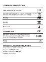
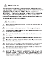
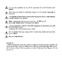
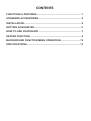
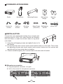
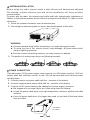
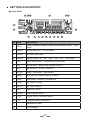
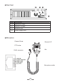
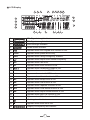
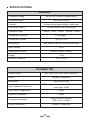
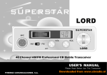
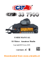
USER MANUAL
10 Meter Amateur Radio
CopyrightCRT France 2015
Downloaded from www.cbradio.nl
and EN 62311.
CONTENTS
FUNCTIONS & FEATURES ..................................................................1
STANDARD ACCESSORIES................................................................2
INSTALLATION .....................................................................................2
GETTING ACQUAINTED ......................................................................5
HOW TO USE YOUR RADIO ...............................................................7
KEYPAD FUNCTION ............................................................................9
BACKGROUND FUNCTION MENU OPERATION .............................12
SPECIFICATIONS...............................................................................13
FUNCTIONS & FEATURES
◆◆ Big LCD displays frequency and all kinds of information
◆◆ FM、AM、USB、LSB、PA mode
◆◆ Frequency Tuning Step 100Hz、1KHz、10KHz、100KHz、1MHz
◆◆ ±1.5KHz CLARLFILER Adjustment
◆◆ Flexible Menu Function and PC Program Software
◆◆ ECHO Function
◆◆ SQ, ASQ Function (FM and AM mode only)
◆◆ RF GAIN Adjustment
◆◆ RF PWR Adjustment
◆◆ SCAN Function
◆◆ Programmable RB Function
◆◆ NB/ANL Function
◆◆ DW DUAL-WATCH Function
◆◆ Offset Frequency Function
◆◆ BEEP Voice Prompt
◆◆ +10KHZ Function
◆◆ SIG、PWR、SWR Function
◆◆ TOT function
◆◆ HI-CUT Function
◆◆ EMG Channel Function
◆◆ SWR Protection
◆◆ Power Supply Voltage Protection
◆◆ Key-Lock Function
◆◆ Six(6) Groups Memory Channel
◆◆ Model Name Customized Function
◆◆ CTCSS/DCS Code(included)
1
STANDARD ACCESSORIES
Radio
Screws for
bracket
Microphone
Pads for
bracket
Mounting Bracket
Adjusting
screws
Microphone
Hanger
Spare Fuses Self-tapping
Screws
(10A,250V)
Non-slip
Mat
power cord
INSTALLLATON
Choose the most appropriate setting from a simple and
practical point of view. Your radio should not interfere
with the driver or crash the driver's knee or leg when
rush brake.
11 Using the self-tapping screws and pads(2 sets) to fix
the bracket.
21 Put the Non-slip mat on the 2 ends of the bracket and put in the radio. Then insert
the adjusting screws and check careful each screws, make sure the screws and
machine will not loose when the car shaking.
31 Choose suitable angle by the 3 screw holes in the two ends of bracket.
Microphone connection
11 Plug microphone connector into jack.
21 Pull on the screw for microphone connector.
2
ANTENNA INSTALLATION
Before using this radio, please install a high efficent and harmonious adjusted
CB antenna, suitable antenna type and correct installation will bring excellent
communication.
To match with the radio, the antenna and cable shall with characteristic impedance of
50ohm, or the antenna system will not efficient enough and will disturb TV, radio or other
electronics.
111 Screw the antenna connector into the antenna jack.
222 Grounding the antenna system to ensure best performance of this radio.
WARNING:
▲ Connect antenna firstly before transmiting, or it might damage the radio.
▲ To avoid the risk of fire, electric shock, radio damage, all base station shall
equip of lightning protector
▲ Be sure choose a matching antenna, you may enquiry our dealers.
333 The position of antenna can be put as following example:
POWER CONNECTION
This radio adopt 13.8V power supply, never connect it to 24V battery, And the 13.8V car
battery shall with sufficient current, or the LCD will become dark and Transmit power
will drop down.
111 Connect positive red power cable with the + terminal of the battery.
222 Connect negative black power cable with the - terminal of the battery.
333 Connect the DC power cable to the transceiver's power supply connector.
▲ We suggest not use cigar lighter as it often bring down the voltage.
▲ Locate the power cable away from high temperature, moisture, portfire and cable
insulator.
▲ Use a full power cable even it is longer than need, do not take off the fuse holder
from the cable.
Connected
to chassis
3
Replacing Fuse
This radio adopt 10A, 250V fuse.
If the fuse blows, determine the reason, then correct the problem.
After the problem is resolved, replace the fuse. If newly installed fuses continue to
blow, disconnect the power cable and contact your autho-rized dealer or an authorized
servicecenter:
111 Pull the two fuse cover in difference direction and open it.
IN-LINE
FUSE HOLDER
10A, 250V FUSE
222 Replace the broke fuse with good one, and close the fuse holder.
333 Be sure to use suggested fuse, or it might damage the radio.
IN-LINE
FUSE HOLDER
IN-LINE
FUSE HOLDER
FUSE
IN-LINE
FUSE HOLDER
Install Microphone Hanger
Choose a ideal location which will not interfere
the driver. Using supplied self-tapping screws and
pads(2 sets) to fix the hanger.
Install External Speaker
If use an external speaker, please choose 8ohm speaker with 3.50mm mono band
(doulbe cable) plug.
111 Locate the external speaker in a suitable place.
222 Plug into the speaker jack.
4
GETTING ACQUAINTED
Front Panel
2 11 12
18
13 14
1
17
16
15
No. Key
3
4
5
6
7
8
9
10
Functions
1
FRQ
Switch between channel mode and frequency mode、offset
setup
2
BAND
Switch band: A-I、ECHO setup
3
MENU
Function Menu key
4
MODE
Switch mode(FM、AM、USB、LSB、PA)、TSQ setup
5
DW
Dual-watch scan、Frequency+10K function
6
RB
RB function、Beep voice prompt function
7
NB
NB function、HI-CUT function
8
SCAN
Scan、Scan add、Scan delete
9
MEM
Use, store or delete memory channel
10
EMG
Emergency Channel; Keypad lock.
11
PWR
RF Power Control
12
RFG
RF Gain Control
13
SQ
Squelch Control
14
CLAR
SSB Clarifier switch
15
VOL
Power On/Off; Volume Control.
16
CH
Channel Switch, Push key.
17
Microphone Jack
18
LCD Display
5
Rear Panel
21
20
19
ANT.
PA.SP.
EXT.SP.
POWER +
22
No. Functions
19
External SP Jack
20
External PA Jack
21
Antenna Jack
22
Power Supply Jack
Microphone
Channel Down
Channel UP
PTT button
Mic
RJ45 connector
Microphone cable
6
LCD Display
7
6
5
11
13 12 15 18 19
22
1
21
2
3
24
4
8
9 10
23
1
RX Signal strength indicator.
2
TX Signal strength indicator.
3
SWR strength indicator.
4
Model name Indicator.
5
14 17 16 20
Appears when the Keypad lock function is ON.
6
FUNC
Appears when press MENU key.
7
EMG
Appears when using Emergency channel.
8
Appears when adjust SSB clarifier frequency.
9
AQ
Appears when use ASQ.
10
SC
Appears when scan function is ON.
11
Appears when modulation mode is ON.
12
CTC
Appears when set with CTCSS code.
13
DCS
Appears when set with DCS code.
14
HIC
Appears when Hi-cut function is ON.
15
BP
Appears when Beep voice is ON.
16
RB
Appears when RB function is ON.
17
REP
Appears when repeater function is ON.
18
DW
Appears when Dual-watch function is ON.
19
NB
Appears when adjust Noise Blanker is ON.
20
IOk
Appears when add 10k function is ON.
21
ECHO
Appears when Echo function is ON.
22
Working band indicator.
23
Appears when scan list is ON.
24
Display of frequency and channel.
7
HOW TO USE YOUR RADIO
OFF/ON Radio
111 Turn VOL clockwise to switch on the radio, the radio emit a beep. When the LCD
displays frequency or channel, the radio is on.
222 Turn VOL anti-clockwise to switch off the radio, the radio is OFF when hear Ka
Ta from the switch.
Volume Control
When the radio is turned on, turn VOL clockwise will increase the volume, turn VOL
anti-clockwise will reduce the volume. The LCD displays VOL: XX (XX stands for the
volume level, total 1-36 levels).
Note: Adjust the volume during communication to get suitable level.
RF Power Control
When the radio is transmitting, turn PWR outer shaft to adjust power. Turn it
clockwise to increase power, anti-clockwise to reduce power.
RF Gain Control
When the radio is receiving, turn RFG inner shaft to adjust RF gain. Turn it clockwise
to increase gain, anti-clockwise to reduce gain.
SQUELCH Control
When the radio is standby, turn SQ outter shaft clockwise to adjust squelch level.
The LCD displays SQ: XX. (XX stands for the squelch level, total 1-36 levels).
SSB Clarifier control
When the radio is transmitting or receiving, turn CLAR inner shaft to adjust USB/
LSB TX or RX frequency. Turn it clockwise to increase frequency, anti-clockwise to
reduce frequency.
Channel Selection
When radio is in channel mode, turn channel knob to select desired channel.
Clockwise to increase, anti-clockwise to reduce channel.
Note: In channel display mode, each press【PUSH】key will increase the
frequency by 10 times of channel step size.
8
Frequency control
111 In frequency mode, press 【PUSH】key, then you can adjust frequency for
present channel.
222 When the frequency is flashing, turn CH clockwise to increase frequency, anticlockwise to reduce frequency.
333 When the frequency is flashing, press【PUSH】again to adjust frequency step
size.
KEYPAD FUNCTION
【FRQ/REP】
Short press【FRQ】to switch between frequency display mode and channel
display mode.
Offset Direction Function
111 Long press 【FRQ】for 2 seconds to enter offset direction function, LCD
displays "REP";
222 Press【PUSH】to select offset, turn channel switch to select;
REPOF: Turn off offset direction function;
REP+: Turn on offset direction function, TX frequency>RX frequency;
REP-: Turn on offset direction function, RX frequency>TX frequency;
333 Press【PUSH】to store and exit.
【BAND/TONE】
Band Selection Function
Short press【BAND】to choose band A-B-C-D-E-F-G-H-I.
Echo Function
111 Long press【BAND】for 2 seconds to enter ECHO function, LCD displays
"ECHO";
222 Long press【BAND】for 2 seconds to turn off ECHO function.
【MENU】
Long press【MENU】for 2 seconds to enter menu list.
【MODE/TSQ】
Modulation Mode
Short press【MODE】to choose mode FM-AM-USB-LSB-PA.
9
CTCSS/DCS Function
111 Long press 【MODE】for 2 seconds to enter CTCSS/DCS function, LCD
displays "CTCSS" or "DCS";
222 Press【PUSH】to set CTCSS/DCS, turn channel switch to select CTCSS/
DCS, then Press【PUSH】to store and exit.
OFF: Turn off CTCSS/DCS function;
CTCSS: 67.0~250.3Hz, Total 38 groups;
DCS: D023N~D754N, Total 104 groups;
Note: This function is available only when install Optional CTCSS board.
【DW/+10K】
Dual-Watch function
111 Short press【DW】to turn on Dual watch, LCD displays "DW";
222 Short press【DW】again or press PTT to exit DW mode;
Frequency+10KHz function
111 Long press【DW】for 2 seconds to turn on frequency +10KHz function, LCD
displays "10K";
222 Long press【DW】for 2 seconds again to turn off frequency +10KHz function.
【RB/BEEP】
RB function
111 Short press【RB】to turn on RB function, LCD displays "RB";
222 Press【PUSH】to select RB frequency, turn on channel switch to select.
OFF~5, total 6 groups.
OFF: Turn off RB function;
333 Press 【PUSH】 to store and exit.
BEEP Voice Prompt function
111 Long press【RB】for 2 seconds to enter BEEP voice prompt function, LCD
displays "RB";
222 Long press【RB】for 2 seconds again to turn off BEEP voice prompt function.
【NB/HCUT】
NB function
111 Short press【NB】to enter NB function, LCD displays "NB";
222 Short press【NB】again to turn off NB function.
HI-CUT function
111 Long press【NB】for 2 seconds to enter HI-CUT function, LCD displays "HIC";
222 Long press【NB】for 2 seconds again to turn off HI-CUT function
10
【SCAN/SKP】
Scan function
111 Short press【SCAN】to enter scan function, LCD displays "SC";
222 In scan mode, Turn channel switch will change scan direction.
333 Short press【SCAN】again to exit.
Add/delete scan list function
111 Long press【SCAN】for 2 seconds to add or delete the current channel from
scan list;
222 When LCD displays "●", current channel is not added to scan list; When LCD
does not display "●", current channel is added to scan list.
【MEM/STOR】
Using memory channel:
111 Short press【MEM】to enter memory channel, turn channel switch to choose
memory channel. M1-M6, Total 6 memory channels.
222 Short press【MEM】again to exit memory channel mode.
Store/Delete memory channel:
111 Store memory channel
When the radio is not in memory channel mode, choose the channel to be
stored, and hold【MEM】enter storage mode, the channel number flashes, Turn
Channel switch to choose the location to be stored (M1-M6), then hold【MEM】
until the flashing channel number disappear, the storage is done.
222 Delete memory channel
In channel mode, hold【MEM】for over 2 seconds, the memory channel
number flashes, turn the CH switch to choose the memory to be deleted. Then
hold【MEM】until the flashing channel number disappear, the delete is done.
【EMG/LOCK】
Choose EMG channel:
Short press【EMG】to use Emergency channel, LCD displays "EMG".
111 Short press【EMG】once to choose CH9;
222 Short press【EMG】again to choose CH19;
333 Short press【EMG】thrice to return to last normal channel.
Keypad Lock Function:
";
111 Long press【EMG】to lock keys, LCD displays "
222 Long press【EMG】again to unlock the keys.
Note: When this function is turned on, only PTT button is valid.
11
BACKGROUND FUNCTION MENU OPERATION
111
222
333
444
555
Press【MENU】for 2 seconds to enter menu list;
Turn Channel switch to select menu No.1 to No.10;
Press【PUSH】to enter the menu setup;
Turn channel switch to select wanted setup;
Press any other key or wait 5 seconds, the setting will be stored and exit.
No.
Function
LCD Display
Values and Descriptions
1
Mic Gain
1-36, Total 36 levels available;
Default: 30.
2
Monitor Gain
1-32, OFF, Total 33 levels available;
Default: OFF. (Shut NOG function)
3
TOT
1-600s, OFF, Total 10minutes available;
Default: 180S. (Shut TOT function)
4
SWR
Protection
OFF: Shut SWR function;
ON: Open SWR function;
Default: ON.
5
Scan Type
SQ: SQ scan function;
TI: Time scan function;
Default: SQ.
6
SSB Clarifier
switch
OFF: Shut frequency adjustment;
R: Open RX frequency adjustment;
T: Open TX frequency adjustment;
RT: Open TX/RX frequency adjustment;
Default: R.
7
Channel
Frequency
switch
CHAN: Channel adjust;
FREQ: Frequency adjust;
Default: FREQ.
8
ASQ Control
01~09: Total 9 Levels;
Default: 05.
9
Offset
frequency
Frequency range: 100Hz~5MHz;
Default: 100KHz.
10
Reset
OPT: All function setup resume default;
ALL: All channels and setup resume default;
Default: OPT.
12
CTCSS code
No.
Freq. (Hz)
No.
Freq. (Hz)
No.
Freq. (Hz)
No.
Freq. (Hz)
1
67.0
11
97.4
21
136.5
31
192.8
2
71.9
12
100.0
22
141.3
32
203.5
3
74.4
13
103.5
23
146.2
33
210.7
4
77.0
14
107.2
24
151.4
34
218.1
5
79.7
15
110.9
25
156.7
35
225.7
6
82.5
16
114.8
26
162.2
36
233.6
7
85.4
17
118.8
27
167.9
37
241.8
8
88.5
18
123.0
28
173.8
38
250.3
9
91.5
19
127.3
29
179.9
10
94.8
20
131.8
30
186.2
DCS code
Code
DSC
Code
DSC
Code
DSC
Code
DSC
No.
(Octal)
No.
(Octal)
No.
(Octal)
No.
(Octal)
1
023
27
152
53
311
79
466
2
025
28
155
54
315
80
503
3
026
29
156
55
325
81
506
4
031
30
162
56
331
82
516
5
032
31
165
57
332
83
523
6
036
32
172
58
343
84
526
7
043
33
174
59
346
85
532
8
047
34
205
60
351
86
546
9
051
35
212
61
356
87
565
10
053
36
223
62
364
88
606
11
054
37
225
63
365
89
612
12
065
38
226
64
371
90
624
13
071
39
243
65
411
91
627
14
072
40
244
66
412
92
631
15
073
41
245
67
413
93
632
16
074
42
246
68
423
94
654
17
114
43
251
69
431
95
662
18
115
44
252
70
432
96
664
19
116
45
255
71
445
97
703
20
122
46
261
72
446
98
712
21
125
47
263
73
452
99
723
22
131
48
265
74
454
100
731
23
132
49
266
75
455
101
732
24
134
50
271
76
462
102
734
25
143
51
274
77
464
103
743
26
145
52
306
78
465
104
754
13
SPECIFICATIONS
GENERAL
Frequency Range
28.000-29.700MHz(Programmable)
Frequency Band
Channel
A/B/C/D/E/F/G/H/I
40channels(programmable)in each band
Frequency Control
Frequency Step
Phase-Locked-Loop Synthesizer
100Hz、1KHz、10KHz、100KHz、1MHz
Frequency Tolerance
± 5.00 ppm
Temperature Range
-20℃ to +50℃
Microphone
with push-to-talk /UP/DN and coiled cord
Input Voltage
13.8V
Dimensions (in mm)
250(W) x 280(L) x 60(H)
Weight
1.5kg
Antenna Connector
UHF, SO239
TRANSMITTER
Power Output
AM: 12W / FM: 30W / SSB: 30W(PEP)
Drain
8A(with modulation)
Modulation
AM/FM/USB/LSB
Inter-modulation Distortion
SSB: 3rd order, more than -25dB; 5th order,
more than -35dB
SSB Carrier Suppression
55dB
Unwanted Sideband
50dB
Frequency Response
AM/FM: 300 to 3000Hz
SSB: 450 to 2500Hz
Output Impedance
50ohms, unbalanced
13
RECEIVER
SSB: 0.25μV for 10dB(S+N)/N at greater than
1/2-watt of audio output
Sensitivity
AM:1.0μV for 10dB(S+N)/N at
greater than 1/2watt of audio output
FM: 1.0μV for 20 dB (S+N)/N at greater than 1/2
watt of audio output
Adjacent-Channel Selectivity
AM/FM: 60dB
Image Rejection
More than 65dB
IF Frequency
SSB: 70dB
AM/FM: 10.695MHz 1st IF, 455KHz 2nd IF
SSB: 10.695MHz
RF Gain Control
45dB adjustable for optimum signal reception
Automatic Gain Control(AGC)
Less than 10dB change in audio output for inputs
from 10 to 100,000 microvolt.
Squelch
Adjustable; threshold less than 1.0μV.
Automatic Squelch Control(only AM/FM)1.0μV
Audio Output Power
3 watts into 8 ohms
Frequency Response
AM/FM: 300 to 3000Hz
Built-in Speaker
8 ohms, round.
External Speaker(Not Supplied)
8 ohms; disables internal speaker when
connected.
14
SSB: 450 to 2500Hz
CONDITIONS OF GUARANTEE
Our transceivers CRT SUPERSTAR are guaranteed on 2 year. The other equipments :
6 months.
Any abnormality of functioning must be indicated to your retailer, who will intervene
or will send it to our technical service for control
The spare parts of our devices are the object of no sending under guarantee
Are excluded of the guarantee:
- the damages caused by accidents, shocks, natural elements (lightning, thunderstorm,
static electricity etc.)
- The transistors of power, the microphones, the fuses, the bad uses: badly adjusted ante
-nna (tos excessive), inversion of polarity, surge, bad connection etc. recognized by our
technical se rvice.
- The interventions having modified the standards of approval of the device.
PROCEDURE ON RETURNING TO THE
AFTER-SALES SERVICE CRT
- If you send back a radio under guarantee for repair : you must pay the freight costs to go.
CRT will pay the freight costs return. If the radio is not under guarantee postal charges are
at your expense.
- each device must be sent accompanied with a photocopy of the invoice as well as with a
descriptive note of the noticed defect
If our AFTER-SALES SERVICE estimates the repair more expensive than the value of the
device, this one will send you an estimate which must have returned to him accepted or
refused. If the estimate is refused, the device will have carriage forward returned.
DECLARATION OF CONFORMITY
We hereby declare under our responsibility that the product :
Description : mobile transceiver HF amateur radio
Brand : CRT
Model : SS 7900
Satisfies all the technical regulation applicable to the product within the scope of
directive R .TTE 1999/5/CE and european standarts.
EN 60950-1+A1+A11+A12
EN 301 489-1
EN 301 489-15
EN 301 783-1
EN301 783-2
EN 62311
The HAM version was approved in the CEPT countries and those non CEPT countries that
implement the CEPT regulation TR 61/01
CEPT Countries Codes : ALB-AND-AUT-AZE-BLR-BEL-BIH-BUL-HRV-CYP-CZEDNK-EST-FIN-F-GEO-D-GRC-HNG-ISL-IRL-I-LVA-LIE-LTU-LUX-MKD-MLT-MDAMCO-MNE-HOL-NOR-POL-POR-ROU-RUS-SMR-SRB-SVK-SVN-E-S-SUI-TUR-UKRG-CVA
Notified body PHOENIX TESTLAB Gmbh Germany
Mr CELESTRANO PHILIPPE
Manager
Date 30/04/2015