1
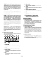
OPERATING MANUAL
Downloaded from www.cbradio.nl
Copyright © 2000 by Magnum International. All rights reserved.
TABLE OF CONTENTS
Introduction ......................................................................................................... 4
Limited Warranty ................................................................................................. 5
Installation ...................................................................................................... 6 - 7
Front Panel Controls .....................................................................................8 - 11
Rear Panel ......................................................................................................... 11
Other Features ................................................................................................... 11
Specifications .................................................................................................... 12
Contact Information ........................................................................................... 12
-3-
INTRODUCTION
Congratulations on your purchase of a Magnum AlphaForce 10 meter FM/AM transceiver. The AlphaForce is
designed to provide years of enjoyment and trouble-free service. There are many features and functions
designed into this transceiver. To ensure that your investment is enjoyed to its fullest extent, please take a
few moments and thoroughly read this manual.
The Magnum AlphaForce is a microprocessor controlled, user programmable radio combining high RF performance with a user-friendly environment. The AlphaForce is built rugged to withstand years of use in harsh
mobile environments. Although engineered with mobile use in mind the AlphaForce, with the addition of a
high quality 10 amp regulated power supply, may be easily adapted to fixed station operation.
Some of the features of the AlphaForce are; an advanced design liquid crystal display that provides the
operator with a full visual account of the transceivers operating status, automatic frequency scanning from
either the front panel or microphone, memory storage of your favorite frequencies, programmable frequency
resolution of either 1 kHz, 10 kHz or 100 kHz, and split (offset) frequency operation for repeater use. These
are just a few of the features that make the AlphaForce a pleasure to own and operate.
IMPORTANT: The Magnum AlphaForce is designed for entry level amateur use. If the transmitter is operated in the United States or within it’s territories a licensed amateur radio operator must be present at the
station. The minimum license class to operate 10 meter phone is Novice/Technician. If you are studying for
your license and want to familiarize yourself with the operation of the radio, the receiver may be operated with
or without a licensed operator present. For more information regarding FCC licensing, contact your nearest
amateur radio dealer, or for complete details contact the American Radio Relay League.
American Radio Relay League (ARRL)
225 Main Street
Newington, CT 06111
Telephone 860-594-0200
Facsimile 860-594-0259
http://www.arrl.org
-4-
LIMITED WARRANTY
Magnum International warrants this product to be free of defects for a period of one (1) year from the original
date of purchase. This warranty is non-transferable. This limited warranty is subject to repair or replacement
of defective components only. This warranty is void if the radio has been tampered with or misused.
IMPORTANT: RETAIN YOUR SALES RECEIPT
The enclosed warranty registration form must be filled out and mailed along with a photocopy of your sales
receipt within 15 days from the purchase date. If the warranty registration form and copy of your sales receipt
are not received the radio is not covered under warranty. Please fill out the enclosed warranty registration
form and send it along with a copy of your sales receipt to:
Magnum International
PO Box 445
Issaquah, WA 98027
Registering your AlphaForce with Magnum provides several benefits:
1) Validates your warranty.
2) Entitles you to free updates and information regarding your radio and new accessories for your radio.
3) Provides possible recovery of lost or stolen radios through our serial number tracking database.
4) Receive your free Magnum logo baseball cap within 30 days after registering.
-5-
INSTALLATION
1. CONTENTS
Unpack and inspect your Magnum AlphaForce for missing or damaged components. Your AlphaForce includes
the following items:
Quantity
1
1
1
1
1
1
Connect the positive (+) red wire of the DC power cord
to a positive 13.8 volt source at the vehicle fuse block.
If connecting to the fuse block, it is recommended that
a switched power source is used so that the power to
the transceiver is disconnected when the vehicle is off.
This will eliminate the possibility of the transceiver draining the vehicle’s battery.
Description
Magnum AlphaForce Transceiver
Microphone with Up/Down Controls
DC Power Cord with Inline Fuse
Mounting Bracket with Hardware
Microphone Hanger with Hardware Set
Operating Manual with Schematic
Connect the negative (-) black wire to a metal part of
the vehicle’s frame, or chassis ground. Make sure that
this is a good ground connection.
The AlphaForce power cord may also be connected
directly to the battery. Connecting directly to the battery has several benefits, the first of which is to maximize RF output. Secondly, the battery is a very large
capacitor and will help eliminate certain types of ambient and vehicle noise. If connecting directly to the
vehicle’s battery, additional power cable may be required. On runs of 8 feet or less use 14-gauge stranded
wire. Use 12-gauge wire on longer runs.
2. MICROPHONE HANGER
The microphone hanger may be attached to the side
of the transceiver, or any other convenient location. Use
the provided screws to attach the microphone hanger
either vertically or horizontally to the side of the transceiver.
3. MOUNTING
When attaching the AlphaForce mounting bracket to
the vehicle, choose a location that will provide easy
access to all front panel controls and air circulation to
the rear panel. When selecting a mounting location,
make sure that there is ample space behind the control deck for the cables. Do not pinch, or bend sharply,
the power or antenna cables. Do not install the
AlphaForce in any compartment that restricts airflow
and do not install in a location that interferes with the
safe operation of the vehicle.
5. ANTENNA CONNECTION
The transceiver will operate using any standard 50ohm ground-plane, vertical, mobile whip, long wire or
similar antenna. The antenna should be rated at 50
watts PEP minimum. A standard SO-239 type antenna
connector is located on the rear panel of the
AlphaForce. Connection is made using a PL-259 and
high grade coaxial cable (RG213, RG58A/U or Mini
RG-8 is recommended).
Attach the mounting bracket to the vehicle first then
mount the AlphaForce to the bracket. If the rear panel
is not accessible you may want to attach the power
and antenna cable prior to mounting.
A ground-plane antenna provides greater coverage and
is recommended for fixed station-to-mobile operation.
For point-to-point fixed station operation, a directional
beam antenna operates at greater distances even under adverse conditions. A non-directional antenna
should be used in a mobile installation; a vertical whip
is best suited for this purpose. The base loaded whip
antenna normally provides effective communications.
For greater range and more reliable operation, a full
quarter wave whip may be used. Either of these antennas uses the metal vehicle body as a ground plane.
4. ELECTRICAL CONNECTIONS
The Magnum AlphaForce is designed to work on any
13.8 volt DC, negative ground, source. The condition
of a vehicle’s electrical system can affect operation. A
low battery, worn generator/alternator, or poor voltage
regulator will seriously impair the performance of the
transceiver. Any of the above conditions could result in
a high level of receiver noise generation or a substantial loss of the transmitter’s RF output. Make sure that
all of these components of your vehicle’s electrical system are in good condition prior to installing the transceiver.
Once the antenna is mounted on the vehicle, route the
coaxial cable so that it is not next to any power cables
or vehicle cables. Connect the PL-259 to the antenna
connector on the rear panel of the AlphaForce. Make
sure that the cables does not interfere with the safe
operation of the vehicle.
CAUTION! VOLTAGE EXCEEDING 15 VDC
WILL DAMAGE THE RADIO. MEASURE VOLTAGE AT BATTERY TERMINALS, WITH VEHICLE
RUNNING, PRIOR TO INSTALLATION!
The Penetrator™ and Super Penetrator™ mobile antennas, available from RF Limited, are the perfect antennas for use with the Magnum AlphaForce. The
Penetrator™ and Super Penetrator™ feature power
ratings of up to 3,500 watts PEP and bandpass ratings
of 1.5 MHz, the widest bandpass of any mobile antenna of its kind.
Before making any electrical connections make sure
the volume/power control on the AlphaForce is in the
“OFF” position.
-6-
6. VSWR
Before use, it is important to determine the antenna
system’s VSWR (voltage standing wave ratio). First,
make sure the SWR bridge (meter) is in good working
order and is calibrated. To ensure your radio is performing properly the VSWR should never exceed 1.5
to 1. Never transmit on any antenna system where the
VSWR exceeds 1.8 to 1. This will stress the output
stage and could destroy the RF transistors; this type of
misuse and failure is not covered under warranty.
Measure the VSWR at the center of the operating band.
Tune the antenna (according to the manufacturer’s
tuning instructions) so that the VSWR is as close to
1.1 to 1 at the center of the operating band.
Next, measure the VSWR at the lowest and highest
frequency of the transceiver. If the antenna has a wide
enough frequency range and band-pass, the VSWR
readings should be below 1.5 to 1 across the entire
operating band. If at the lower or upper end of the transceiver operating frequency, the VSWR measures more
than 1.5 to 1, it is recommended that the antenna be
re-tuned before operating on those frequencies.
If you are experiencing unusual VSWR readings check
for the following possible problems:
1) Make sure that the antenna is installed properly and
grounded.
2) Check all coaxial cable and connectors for defects
and poor routing.
3) If testing a vehicle installation, make sure that all
vehicle doors are closed when testing.
4) Do not test near or around large metal objects or
buildings.
7. IGNITION NOISE
In certain vehicle installations, electrical noise or interference may be present in the receive audio of the transceiver. Typically the vehicle’s ignition system or more
specifically the alternator generates this noise. The
Magnum AlphaForce is equipped with a noise blanker
circuit that is designed to improve, and in many instances eliminate, this electrical noise.
In extreme cases, the noise blanker may not eliminate
all the electrical noise. In such cases, an after-market
alternator noise or ignition noise filter can be purchased
and installed according to the manufacturer’s instructions. If purchasing an alternator noise filter for the
Magnum AlphaForce make sure the filter is rated for
at least 10 amps continuous current draw.
-7-
16
15
14
17
20
18
21
19
22
23
13
12
24
2
1
4
3
7
5
6
9
8
10
11
FRONT PANEL CONTROLS
1. OFF / VOLUME CONTROLS
OFF: Turns the power to the radio on and off.
4. RF GAIN CONTROL
Adjusts the receiver sensitivity to both signals and background noise. This affects the distance at which a signal can be detected. Turning the control counterclockwise reduces the receiver sensitivity. This is particularly useful in areas where large volumes of traffic (signals) are present. The S/RF meter (refer to 13) indicates the received signal’s strength.
VOLUME: Adjusts the AF gain, or volume of the received audio. Turn clockwise to increase and counterclockwise to decrease.
2. SQUELCH CONTROL
Used to eliminate background or “white” noise when
monitoring strong signals. Also used to activate SCAN
feature (refer to 20). To properly adjust the squelch
circuit, start rotating the control slowly clockwise until
the received white noise disappears.
5. RB / S/RF / CAL / SWR CONTROL
ROGER BEEP: RB position activates the end of transmission, or roger beep, tone. When activated a 1 kHz
tone will automatically transmit upon release of the PTT
switch. This notifies contacts that your transmission
has ended and you are ready to receive their signal. To
turn off the roger beep, put the switch in the S/RF position. NOTE: In the RB position, the meter (refer to 13)
measures S/RF.
3. MICROPHONE GAIN CONTROL
Increases or decreases the energy developed in the
microphone amplifier circuit. The gain increases as the
control is rotated clockwise.
For optimum setting, press the push-to-talk (PTT)
switch on the microphone. While speaking in a constant tone (such as saying the word, “four-r-r-r-r”) adjust the mic gain control until the LCD peak reading RF
meter (refer to 24) reads +30. Next, rotate the control
counterclockwise until the +30 segment of the display
starts to flicker. The microphone gain should now be
set to maximum modulation without distortion.
SIGNAL STRENGTH / RF METER: S/RF position activates the meter (see 13) to measure receive signal
strength and transmitter RF output power.
-8-
CALIBRATE: CAL position activates the meter to calibrate for SWR measuring. To calibrate for SWR, set
the switch to the CAL position, press the PTT switch
and rotate the calibrate control (refer to 7) until the meter
(refer to 13) needle lines up with the CAL mark on the
far right side of the meter. Once lined up, release the
PTT. The transceiver is now ready to measure SWR.
NOTE: When first attempting to calibrate make sure
the transceiver is in the AM mode (refer to 22). If it is
not possible to calibrate in AM, then switch to FM mode.
11. FREQUENCY
Rotate clockwise or counterclockwise to select the
desired frequency.
12. MICROPHONE INPUT
A 6-pin, lock ring type, microphone connector is used.
Microphone wiring is as follows:
Pin 1 : Microphone Audio
Pin 2 : Receive
Pin 3 : Transmit
Pin 4 : Down (Up w/ 22K Ohm Resistor)
Pin 5 : Ground
Pin 6 : +13.8 VDC
STANDING WAVE RATIO: SWR position activates the
meter to measure the standing wave ratio of the transceiver and antenna system. After the meter is calibrated, set the switch to the SWR position and press
the PTT switch. The meter (refer to 13) will measure
the SWR. For optimum performance the SWR should
be below 1.5 to 1, the first green segment on the SWR
portion of the meter indicates an acceptable standing
wave ratio.
13. METER
The meter indicates receive signal strength, RF output
power, SWR calibrate and SWR. The top horizontal
bar graph indicates calibration and measuring of the
standing wave ratio. The center bar graph indicates
RF output power. The bottom bar graph indicates receive signal strength.
6. ALL MODE TALK BACK CONTROL
All Mode Talk Back, a Magnum exclusive, is an independent talk back monitor. The AMT functions in all
modes and allows the operator to monitor the transmitted audio of the AlphaForce. To increase the volume of the talk back rotate the control clockwise. To
decrease rotate counterclockwise. To turn off the talk
back rotate the control completely counterclockwise.
14. PUSH-TO-TALK SWITCH
Press and hold the switch to transmit. TX will appear
on the LCD screen when transmitting. Release the
switch to receive.
15. UP and DOWN FREQUENCY CONTROLS
Allows remote operation of the frequency control. Press
the up arrow to increase the frequency and press the
down arrow to decrease the frequency.
7. CALIBRATE CONTROL
Rotate to calibrate the meter (refer to 13) for SWR measurements. See instruction 5 for more information.
IMPORTANT!
Operating some of the features in 16 through 23 require the use of the function control. To activate the
function control, momentarily push the FUNC (16) control, the FUNC prompt will be displayed in upper lefthand corner of LCD. Push the control again to deactivate the function control.
8. ECHO ON/OFF and VOLUME CONTROL
Turns on and off the echo feature, and varies the volume or number of repetitions. To turn on the echo feature and increase the echo volume, rotate the control
clockwise. To turn off the echo feature rotate the control completely counterclockwise to the OFF position.
16. FUNCTION
This control is used to operate the functions that are
printed below the control buttons. To activate, press
and release. FUNC will be displayed on the LCD indicating that the function command is activated. After
you have pressed one of the buttons the FUNC prompt
will disappear from the screen.
9. ECHO DELAY CONTROL
Varies the amount of delay, or duration of the echo repetition. Rotate clockwise to increase the amount of
delay and counterclockwise to decrease.
10. POWER
Rotate clockwise to increase RF output power. Rotate
counterclockwise to decrease RF output power.
17. STEP / NB / 1
STEP: The STEP control selects frequency resolution
in either 1 kHz, 10 kHz or 100 kHz steps. Press the
STEP button, one of the digits will flash on and off.
Press the STEP button again to change stepping resolution.
Variable RF output power allows low power transmitting for QRP operation in compliance with the FCC request for reduced signal strength during periods when
propagation levels are high.
-9-
To tune frequencies in either 10 kHz or 100 kHz increments, press the STEP button until the desired digit is
flashing. Rotate the FREQUENCY control in either direction. The entire frequency range of the Magnum
AlphaForce can be stepped through in 10 or 100 kHz
increments.
SHIFT: Used for programming offsets to operate repeater networks. The AlphaForce can transmit and receive on different frequencies.
To program the offset, press the FUNC button and hold
down the SHIFT button for 3 or more seconds. Three
digits will appear on the LCD. This is the offset frequency in kHz. Rotate the FREQUENCY control until
the desired offset frequency is displayed. To return to
the main display press the FUNC button and hold down
the SHIFT button for 3 or more seconds, or momentarily press the PTT button on the microphone (the
transmitter will not be engaged).
To tune in 1 kHz increments, press the STEP button
until the 1 kHz digit flashes on and off. Rotate the FREQUENCY control. NOTE: When stepping in 1 kHz increments, you are limited to tuning within a 10 kHz
frequency range.
NB: Turns the noise blanker and automatic noise limiter on and off. The noise blanker circuit eliminates pulse
type interference usually associated with automotive
ignition systems. The automatic noise limiter reduces
atmospheric related noise. To activate the NB and ANL,
press the FUNC control and then press the NB button.
NB and ANL will appear on the LCD indicating the noise
blanker and ANL are turned on. To turn off the NB and
ANL, repeat the same process.
To activate the programmed offset frequency, press
the FUNC button, and then press the SHIFT button
once. +SHIFT is displayed on the LCD. The AlphaForce
will now transmit on the frequency that is XXX kHz
greater than the displayed, or receive, frequency (XXX
represents the programmed offset frequency in kHz).
To transmit on the frequency that is XXX kHz lower
than the displayed, or receive, frequency press FUNC,
then the SHIFT button. Repeat this until -SHIFT is displayed on the LCD.
1: Memory Channel 1. After programming this button
is memory channel 1. See M.LOAD \ M.SAVE control
for programming instructions.
To disengage the programmed offset frequency, press
the FUNC button and then press the SHIFT button.
Repeat this until the SHIFT indicator is no longer displayed on the LCD.
18. CALL / 2
CALL: The call frequency is 29.300 MHz, FM. The
radio’s operating frequency and mode are automatically reset to this when the CALL button is pressed.
3: Memory Channel 3. After programming this button
is memory channel 3. See M.LOAD \ M.SAVE control
for programming instructions.
2: Memory Channel 2. After programming this button
is memory channel 2. See M.LOAD \ M.SAVE control
for programming instructions.
21. LCR / RPT / 4
LCR: Press the last channel recall button to return to
the last frequency and mode that was transmitted on
for more than 3 seconds.
19. DIMMER
Press the DIM, or dimmer control, to decrease the
amount of back-lighting on the front panel and LCD
screen.
RPT: Repeater Access Tone. Most repeaters require
an 88.5 Hz tone burst to access. To activate the 88.5
Hz tone burst, press the FUNC control and then press
the RPT button. RPT will appear on the LCD indicating
that the tone burst will now automatically be transmitted whenever the PTT is pressed. To deactivate, repeat the same process.
20. SCAN / SHIFT / 3
SCAN: Scans in increments of 10 kHz. There are two
ways to scan using the front panel controls.
(1) Receive Audio On Scanning: Press the SCAN button. Scan rate is one step every 5 seconds. To stop
scanning press the SCAN button again, or momentarily press the PTT button on the microphone (scanning will stop without transmitting).
(2) Receive Audio Mute Scanning: Carefully rotate the
squelch control a minimum excursion (refer to 2) until
the receive audio is off. The receiver scan rate will now
be five frequencies per second. When a signal is detected the squelch is automatically disengaged and the
scanning is paused. The squelch circuit will automatically re-engage and the receiver will continue to scan
the moment the received signal is no longer detected.
4: Memory Channel 4. After programming this button
is memory channel 4. See M.LOAD \ M.SAVE control
for programming instructions.
22. MODE / TONE / 5
MODE: Press the MODE control to select the operating mode. The operating mode is indicated on the liquid crystal display, AM or FM.
- 10 -
TONE: Press the FUNC button, and then press the
tone button to turn on the receive audio tone control.
TONE will appear on the LCD indicating the feature is
activated. This feature will roll-off high frequency noise
(i.e. “white” noise). Under many operating conditions
this will improve the clarity and understanding of received signals.
5) NB and ANL
Indicates that both the noise blanker and the automatic noise limiter are active.
6) TONE
Indicates that the receive audio tone low feature is
active.
7) 5 DIGIT FREQUENCY DISPLAY
Indicates transmit and receive operating frequencies.
8) TX
Indicates that the transmitter is on.
9) FM / AM
Indicates the selected operating mode.
10) PEAK READING RF POWER METER
Indicates relative peak RF output power.
5: Memory Channel 5. After programming this button
is memory channel 5. See M.LOAD \ M.SAVE control
for programming instructions.
23. M.SAVE / M.LOAD
M.SAVE: To save in memory a specific frequency and
operating mode, select the desired mode and rotate
the FREQUENCY control to the desired frequency.
Press the FUNC button, and then press the M.SAVE
button. S will appear on the LCD next to the frequency.
While S is displayed, immediately press any of the
memory channel buttons (1 - 5). The mode and frequency is now saved into memory. If the S indicator
disappears before you press the memory channel button, the information will not be saved and the process
must be repeated.
REAR PANEL
1. External Speaker Jack
An external speaker jack is located on the rear panel
of the transceiver. The Magnum AlphaForce is designed to accept any standard 8 ohm external speaker
for use with two-way transceivers.
OTHER FEATURES
1. PROGRAMMING TONE
This tone sounds each time the CPU is being programmed. It is helpful, in the beginning so you can be
sure the command has been entered. You may turn off
the tone by simply pressing the PTT switch on the microphone and turning on the ON/OFF POWER switch
at the same time. To turn the tone back on, repeat the
same process.
M.LOAD: To load, or recall, any of the saved memory
channels press the M.LOAD button. L will appear on
the LCD for several seconds. While the letter is displayed press the desired memory channel button (1 5). The programmed mode and frequency will be displayed.
24. LIQUID CRYSTAL DISPLAY
The LCD screen is the status display for the majority
of the transceiver’s functions.
1
9
2
3
4
5
6
7
2. MEMORY BACK UP
The AlphaForce features a super-capacitor back up
for the 5 memory channels. The AlphaForce can be
disconnected from a power source for approximately
4 or 5 days before the memory is lost.
8
10
1) FUNCTION
Indicates the function button has been activated
and that the function dependent controls may be
accessed.
2) SCAN
Indicates that the transceiver is in scan mode.
3) +SHIFT / -SHIFT
Indicates that the split or offset frequency function
is activated.
4) RPT
Indicates that the repeater access tone burst function is active.
- 11 -
GENERAL SPECIFICATIONS
Frequency Coverage
Antenna Impedance
Frequency Control
Frequency Accuracy
Power Requirement
Current Consumption
Dimensions
Weight
:
:
:
:
:
:
:
:
Transmit and Receive ...................................... 28.000 to 29.699 MHz
50 ohm, unbalanced
Digital Phase-Lock Loop (PLL) Synthesizer
Better than +10 ppm from 0 - 40 0C after 15 min. warm up
12 - 13.8 V DC, negative ground
6 amps maximum
7.75 x 2.5 x 10.75 in (W x H x D)
4 lbs
TRANSMITTER SPECIFICATIONS
Power Output
Tuning Steps
Final Transistors
Spurious Emissions
Carrier Suppression
FM Deviation
Audio Response
Frequency Response
Microphone Impedance
:
:
:
:
:
:
:
:
:
:
FM......................................................................................... 30 Watts
AM ................................................... 9 Watts Average / 30 Watts PEP
1 kHz / 10 kHz / 100 kHz
2SC1969 (x2)
More than 50 dB below peak output power
More than 40 dB below peak output power
+/- 2 kHz maximum
More than 30dB below peak output
400 to 2800 Hz
ECM, 600 to 1K ohms
RECEIVER SPECIFICATIONS
Circuit Type
Intermediate Frequencies
Sensitivity
Selectivity
Adjacent Channel Rejection
IF Rejection
Frequency Response
Audio Output Power
Audio Output Impedance
:
:
:
:
:
:
:
:
:
:
:
Dual-Conversion Superheterodyne
1st IF ................................................................................ 10.695 MHz
2nd IF ..................................................................................... 455 kHz
AM ................................................................ 1.0 µV at 10 dB S + N/N
FM................................................................... 0.3 µV at 12 dB SINAD
AM / FM .......................................... 6.0 kHz (-6 dB) / 18 kHz (-60 dB)
Better than 70 dB
Better than 80 dB for all frequencies
250 to 3000 Hz
2 watts minimum at 10% THD with an 8 ohm load
8 ohms
MAGNUM INTERNATIONAL
A Division of RF Limited
PO Box 445 • Issaquah WA 98027
Telephone 425-558-9592 • Facsimile 425-558-9704
Technical Support Only 1-877-MAGNUM-9 (1-877-624-6869)
http://www.magnum-radio.com
E-Mail [email protected]