1
X-310™ Users Manual
Table of Contents
Trademark and Copyright Information................................................................................................................ 5
Warranty................................................................................................................................................................ 6
FCC Statement...................................................................................................................................................... 7
Installation Guidelines (Read Before Installing)................................................................................................ 8
Section 1: Introduction......................................................................................................................................... 9
1.1 X-310™ Features................................................................................................................................... 10
1.2 Applications........................................................................................................................................... 11
1.3 X-310™ Models Available..................................................................................................................... 12
1.3.1 Optional Accessories........................................................................................................................ 12
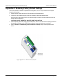
1.4 Connectors & Indicators....................................................................................................................... 13
1.5 Accessing X-310™................................................................................................................................ 14
Section 2: Installation and Setup ..................................................................................................................... 15
2.1 Mounting................................................................................................................................................ 15
2.1.1 Wall Mounting................................................................................................................................... 15
2.1.2 DIN-Rail Mounting............................................................................................................................ 15
2.2 Connection............................................................................................................................................. 16
2.2.1 Power Supply Connection................................................................................................................ 17
2.2.2 Relay Connection............................................................................................................................. 18
2.2.3 Digital Input Connections.................................................................................................................. 20
2.2.4 Temperature/Humidity Sensor Connection ...................................................................................... 22
2.2.5 Network Connection......................................................................................................................... 24
2.3 Establishing Communications for Setup............................................................................................ 25
2.3.1 Method 1: Assign a Temporary IP address to X-310™ .................................................................... 25
2.3.2 Method 2: Assign a Temporary IP Address to the Configuration Computer .....................................27
2.4 X-310™ General Settings Setup Pages .............................................................................................. 30
2.4.1 Information Tab................................................................................................................................. 31
2.4.2 Network Tab...................................................................................................................................... 32
2.4.3 Adv. Network Tab.............................................................................................................................. 36
2.4.4 Password Tab................................................................................................................................... 39
2.4.5 Date/Time Tab .................................................................................................................................. 40
2.4.6 Logging Tab...................................................................................................................................... 44
2.4.7 Events Scheduler Tab....................................................................................................................... 47
2.4.8 Script Tab ......................................................................................................................................... 51
2.4.9 Control Page Setup Tab.................................................................................................................... 53
2.5 X-310™ I/O Setup Pages ...................................................................................................................... 55
2.5.1 Digital Input Tab................................................................................................................................ 56
2.5.2 Counters Tab.................................................................................................................................... 58
2.5.3 Vin Tab.............................................................................................................................................. 60
2.5.4 1-Wire Sensors Tab.......................................................................................................................... 63
2.5.5 Relay Setup Tab............................................................................................................................... 66
2.5.6 Remote Relays Tab.......................................................................................................................... 74
2.5.7 External Variables............................................................................................................................. 80
2.6 X-310™ Monitor and Control Pages .................................................................................................... 83
Page 2
Xytronix Research & Design, Inc.
X-310™ Users Manual
2.6.1 Control Page Tab.............................................................................................................................. 84
2.6.2 Log File Tab...................................................................................................................................... 85
Section 3: Operation........................................................................................................................................... 87
3.1 Browser Operation................................................................................................................................ 87
3.2 XML Operation....................................................................................................................................... 90
3.2.1 state.xml........................................................................................................................................... 90
3.2.2 eventX.xml........................................................................................................................................ 92
3.2.3 Diagnostics.xml................................................................................................................................. 93
3.3 HTTP GET Requests (for custom applications).................................................................................. 95
3.3.1 Using GET for Control and Monitoring.............................................................................................. 95
3.3.2 HTTP GET Event Configuration........................................................................................................ 95
3.3.3 Common Base Ten Values for Event Days....................................................................................... 96
3.4 Modbus Operation................................................................................................................................. 97
3.4.1 X-310™ Function Code Summary.................................................................................................... 97
3.4.2 PLC Device Addressing.................................................................................................................... 98
3.4.3 X-310™ Full Address Table.............................................................................................................. 99
3.4.4 Read Coils - Modbus Function Code 01 (0x01).............................................................................. 100
3.4.5 Read Discrete Inputs – Modbus Function Code 02 (0x02)............................................................. 101
3.4.6 Read Sensors – Modbus Function Code 03 (0x03) ....................................................................... 102
3.4.7 Write Single Coil – Modbus Function Code 05 (0x05).................................................................... 103
3.4.8 Write Multiple Coils - Modbus Function Code 15 (0x0F)................................................................. 104
3.4.9 Write Multiple Registers – Modbus Function Code 16 (0x10)......................................................... 105
3.5 Email Notification................................................................................................................................ 106
3.5.1 Email Notification Description......................................................................................................... 106
3.5.2 Email Notification Setup ................................................................................................................. 106
Appendix A: Restoring Factory Default Settings........................................................................................... 108
Appendix B: Installing New Firmware............................................................................................................. 109
Requirements
Setup
Device Upgrade Procedure
Appendix C: Accessing X-310TM Over the Internet....................................................................................... 111
IP Addresses
A Simple Local Area Network
A Simple LAN connected to the Internet
Port Forwarding
Accessing Setup Pages
Appendix D: Log Files ..................................................................................................................................... 115
Data Log File – log.txt
System Log File – syslog.txt
Appendix E: External Server and Remote Services....................................................................................... 117
Accessing X-310™ with Custom Software or Third Party Applications
Using an External Web Server
Direct Server Control
Remote Services
Connection String
Appendix F: SNMP Requests, Objects and Community Strings...................................................................119
Xytronix Research & Design, Inc.
Page 3
X-310™ Users Manual
Standard Objects
Xytronix Objects
Password
Appendix G: BASIC Scripts............................................................................................................................. 122
Structure
Supported Statements
User-Defined Variables
Predefined Variables
External Variables
Testing and Debugging
Appendix H: Specifications............................................................................................................................. 130
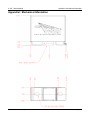
Appendix I: Mechanical Information............................................................................................................... 133
Alphabetical Index............................................................................................................................................ 134
Page 4
Xytronix Research & Design, Inc.
X-310™ Users Manual
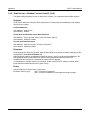
Trademark and Copyright Information
Trademark and Copyright Information
This document is Copyright ©2012-2015 by Xytronix Research & Design, Inc. All rights reserved.
X-310™, WebRelay™, ControlByWeb™, and Xytronix Research & Design™ are trademarks of Xytronix
Research & Design™, Inc. 2005-2015.
All other trademarks are the property of their respective owners.
All parts of this product and design including but not limited to firmware, hardware design, schematics,
PCB layout, concept, graphics, users manual, etc., are property of Xytronix Research & Design, Inc.
©2005-2015. X-310™ may not be opened, disassembled, copied or reverse-engineered.
No part of this manual may be reproduced or transmitted in any form or by any means, electronic or
mechanical, including photocopying or scanning, for any purpose other than the personal use by the
purchaser of this product. Xytronix Research & Design, Inc., assumes no responsibility for any errors
that may appear in this document.
Whereas reasonable effort has been made to make the information in this document as useful and
accurate as possible, Xytronix Research & Design, Inc. assumes no responsibility for the application,
usefulness, or completeness of the information contained herein. Under no circumstance will Xytronix
Research & Design, Inc. be responsible or liable for any damages or losses including direct, indirect,
special, incidental, or consequential damages or losses arising from either the use of any information
contained within this manual or the use of any products or services referenced in this manual.
Xytronix Research & Design, Inc. reserves the right to change any product’s features, specifications,
documentation, warranties, fee schedules, and conditions at any time and without notice.
Xytronix Research & Design, Inc.
Page 5
Warranty
X-310™ Users Manual
Warranty
This Xytronix Research & Design, Inc. product has a warranty against defects in material and
workmanship for a period of one year from the date of shipment. During the warranty period, Xytronix
Research & Design, Inc. will, at its option, either repair or replace products that prove to be defective.
This warranty is extended to the original purchaser of the equipment only.
For warranty service or repair, the product must be properly packaged, and returned to Xytronix
Research & Design, Inc. The purchaser shall prepay all charges for shipping to Xytronix Research &
Design, Inc., and Xytronix Research & Design, Inc. will pay the shipping charges to return the product to
the purchaser as long as the product is shipped within the United States. If the product is shipped
outside of the United States, the purchaser shall pay all shipping charges, duties, and taxes.
Limitation
The foregoing warranty shall not apply to defects or damage resulting from improper use or misuse,
unauthorized repair, tampering, modification, improper connection, or operation outside the
electrical/environmental specifications for the product. Further, the warranty does not cover Acts of God,
such as fire, flood, hurricanes, and tornadoes. This warranty does not cover damage to property,
equipment, direct, indirect, consequential, or incidental damage (including damage for loss of business
profit, business interruption, loss of data, and the like) arising out of the use or misuse of this product.
UNDER NO CIRCUMSTANCES WILL THE LIABILITY OF XYTRONIX RESEARCH & DESIGN, INC. TO
THE PURCHASER OR ANY OTHER PARTY EXCEED THE ORIGINAL PURCHASE PRICE OF THE
PRODUCT, REGARDLESS OF THE FORM OF THE CLAIM. No other warranty is expressed or implied.
Xytronix Research & Design, Inc. specifically disclaims the implied warranties or merchantability and
fitness for a particular purpose. Some jurisdictions may not allow the exclusion of limitation of liability for
consequential or incidental damage.
Page 6
Xytronix Research & Design, Inc.
X-310™ Users Manual
FCC Statement
FCC Statement
This device complies with Part 15 of the FCC Rules. Operation is subject to the following two conditions:
- This device may not cause harmful interference.
- This device must accept any interference received, including interference that may cause undesired
operation.
Warning
This equipment has been tested and found to comply with the limits for a Class B digital device,
pursuant to Part 15 of the FCC Rules. These limits are designed to provide reasonable protection. This
equipment generates, uses and can radiate radio frequency energy and, if not installed and used in
accordance with the instructions, may cause interference to radio communications. There is no
guarantee, however, that interference will not occur in a particular installation. If this equipment does
cause harmful interference to radio or television reception, which can be determined by turning the
equipment off and on, the user is encouraged to try to correct the interference by one or more of the
following measures:
-
Reorient or relocate the receiving antenna.
Increase the separation between the equipment and receiver.
Connect the equipment into a relay on a circuit different from where the receiver is connected.
Consult the dealer or an experienced radio/TV technician for help.
Notice
Changes or modification not expressly approved by the party responsible for compliance could void the
user’s authority to operate the equipment.
Xytronix Research & Design, Inc.
Page 7
Installation Guidelines (Read Before Installing)
X-310™ Users Manual
Installation Guidelines (Read Before Installing)
- This unit must be installed by qualified personnel.
- This unit must not be installed directly outdoors.
- This unit must not be used for medical, life saving purposes, or for any purpose where its failure
could cause serious injury or the loss of life.
- This unit must not be used in any way where its function or failure could cause significant loss or
property damage.
Security Notes
X-310™ does not employ a general purpose computer operating system and does not have features,
such as telnet, FTP, SSH, nor uncontrolled open ports. This means it is unlikely for someone to ‘break in’
to X-310™ and access other devices on your local network. The simplicity of X-310™ makes it a
inherently secure device. Nevertheless, as with any device installed on a network, appropriate security
precautions should be observed.
If X-310™ is installed on the Internet, it is recommended that passwords be enabled for the Control
Page. Passwords should be at least 8 characters in length and use a combination of upper and lower
case letters and numbers. For additional security, a firewall may be used to limit access to selected IP
addresses. Another option may be to set up a Virtual Private Network (VPN) between the network where
X-310™ resides and the client machine (web browser, another, ControlByWeb™ product, etc.).
Final Installation Notes
This ControlByWeb™ product supports connection to 10 Mbps and 100 Mbps networks. Although 100
Mbps networks are faster, the amount of data transferred to and from this device is very minimal and
little, if any, performance increase will be gained by setting it to 100 Mbps. There are advantages,
however, to operate this device at 10 Mbps. At 10 Mbps, less power is required, the unit runs cooler, and
the lifetime of the product will be extended.
Any changes to the Ethernet settings will require a removing and re-applying power to X-310™.
Page 8
Xytronix Research & Design, Inc.
X-310™ Users Manual
Introduction
Section 1: Introduction
X-310™ is a multi-function web-enabled module for control and monitoring. The X-310™ includes four
dry-contact relays, four digital inputs, two pulse counters and 1-wire bus with support for up to 4
temperature/humidity sensors. It can be controlled and/or monitored over any IP network including
private networks, IP-based industrial control networks, and the Internet. Users can operate the X-310™
using a web browser, or custom applications can be written to control the X-310™ from a computer,
PLC, or other automation controller. In addition, custom control scripts can be written and executed
using BASIC programming language.
Other outstanding features of other ControlByWeb products are also included, such as email notification,
BASIC scripting, scheduling, and logging. The X-310™ can also control up to 16 remote relays, can
graph logged data with any HTML 5 compliant web browser, and can monitor the supply voltage.
The X-310™ supports a number of Ethernet protocols with it's built-in server, including HTTP,
Modbus/TCP, SNMP, NTP, and XML.
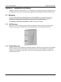
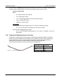
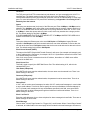
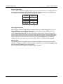
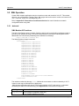
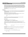
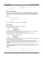
Figure 1.1 - Product Image
Xytronix Research & Design, Inc.
Page 9
Introduction
X-310™ Users Manual
1.1 X-310™ Features
Relay Outputs (4)
Control relays with a web browser, timers, input changes, or programmable logic. The relay contacts are
normally open with the common terminal tied together.
Digital Inputs (4)
View state of inputs with a web browser. Use inputs to control relays, trigger email messages, or use
first two inputs as pulse counters. Inputs have common terminal tied together.
Remote Relays (16)
Control relays on other ControlByWeb products.
Temperature or Humidity Digital Sensor Inputs (4)
Monitor temperature and/or humidity sensors - control relays or trigger email messages based upon
temperature and humidity values.
Power Supply Voltage
The power supply voltage (Vin+) is monitored internally. This value can be monitored, logged, and
used to control local/remote relays. It can also be configured to send email notifications.
Real-time Clock
Manual or NTP capability.
Event Scheduler
Program up to 100 control events based on time and date conditions.
Automatically switch from weekday to weekend or holiday schedules.
Logging
Configurable logging of inputs, temperature, humidity, Vin+, and relay states.
System logging of device operating parameters and events, such as power reset and NTP requests.
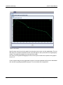
Graphing
Logged data can be graphed directly inside any HTML 5 compatible web browser.
Email Notification
Send email alerts based on any sensor or input conditions, such as temperature, time, digital inputs,
power supply levels, and more. Send text messages to a cell phone through a wireless carrier's
email bridge.
BASIC Script
Additional flexibility is provided through custom scripts using an easy-to-learn BASIC interface.
Web Server and Protocols
All configurable through the built-in, password protected web server. Additional interface options
include XML, Modbus/TCP, and SNMP. IP address configuration can be either static or DHCP.
Page 10
Xytronix Research & Design, Inc.
X-310™ Users Manual
Introduction
1.2 Applications
X-310™ was designed to meet a broad range of industrial applications. It works very well as a standalone
device that can be controlled using a web browser, or as a convenient way to add I/O to a computer. It can
easily be configured using simple menus and drop-down lists, or it can run simple BASIC scripts. Many of
its features such as scheduling, logging, input state monitoring, and the ability to control up to 20 relays (4
internal and 16 remote relays on other devices) make the X-310™ a very powerful, yet simple controller.
You can use the X-310™ to control motors, lights, coils, pumps, valves, bells, etc. You can also use it to
monitor alarms sensors, switches, fluid level switches, battery voltage, temperature, humidity, and much
more. A few example applications include:
- Bell Controller
- I/O Extender
- Industrial Thermostat
- Solar Energy Controller
- Process Controller
- Process Monitor
Xytronix Research & Design, Inc.
Page 11
Introduction
X-310™ Users Manual
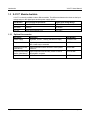
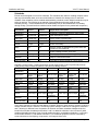
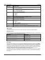
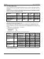
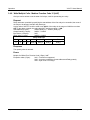
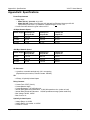
1.3 X-310™ Models Available
X-310™ is currently available in three different models. The differences between the three are the input
voltage range on the digital inputs and the power supply options.
Part Number
Power Supply Requirements
digital Input Voltage Range
X-310-I
9-28VDC
4-12VDC
X-310-24I
9-28VDC
11-26VDC
X-310-E
Power Over Ethernet or 5V
4-12 VDC
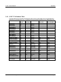
1.3.1 Optional Accessories
Page 12
Accessory
Description
Part Number
Power Supply
Regulated, 12V DC, 1.5Amp (100-240V AC Input)
PS12VW1.5-B
Temperature Sensor
Digital temperature sensor with 12 inch wire leads.
Note: Leads may be extended
X-DTS-U
Temperature Sensor
(Wall Mount)
Digital temperature sensor housed in vented plastic
enclosure
X-DTS-WM
Temperature/Humidity Digital temperature and humidity sensor housed in
Sensor (Wall Mount) vented plastic enclosure
X-DTHS-WM
Spare Connector
X-TERM14A
14-Pin Connector Pinout
Xytronix Research & Design, Inc.
X-310™ Users Manual
Introduction
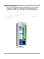
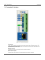
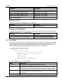
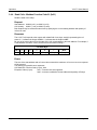
1.4 Connectors & Indicators
Figure 1.4a - Connections & Indicators
I/O Connector
X-310™ has a 14-position removable screw terminal connector and an Ethernet connector. The
terminal connector is used to provide power to the module and connect relays, digital inputs and
temperature/humidity sensor inputs.
Network Connector
The Ethernet connector is a standard, 8-position modular receptacle.
Module Power Indicator
The green Power LED indicator is illuminated whenever the module is powered.
Xytronix Research & Design, Inc.
Page 13
Introduction
X-310™ Users Manual
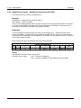
Relay Indicators
Four yellow LEDs illuminate when the corresponding relay is energized. When a relay is energized,
the common and normally open contacts are closed. All four relays share the same common
connection.
Ethernet Indicators
The LINK LED is illuminated green when the module is properly connected to an Ethernet network
and is ready to communicate. Network communications will only occur if this LED is illuminated. The
ACT LED flashes yellow when activity is detected on the network.
1.5 Accessing X-310™
Standard Access Using a Web Browser
X-310™ has a built-in web server that provides simple web pages that can be accessed directly using a
standard web browser. This allows users to access the unit with NO SPECIAL SOFTWARE installed on
their computer. This is ideal for applications that require a quick, simple solution that does not need to be
accessible to more than a few people. This configuration is simple to setup, simple to use, and can be
accessed from just about any computer or smart phone.
Note: Network routers may need to be configured to allow access from computers outside of the local
network (see Appendix C: Accessing X-310TM Over The Internet).
Page 14
Xytronix Research & Design, Inc.
X-310™ Users Manual
Installation and Setup
Section 2: Installation and Setup
Installation consists of mounting the X-310™, connecting it to an Ethernet network, providing power, and
configuring via a web browser, wiring the relays, digital inputs and temperature and/or humidity sensors.
2.1 Mounting
X-310™ can be mounted to a standard (35mm by 7.55mm) DIN-Rail. Or it can be wall mounted. It
should be mounted in a clean, dry location where it is protected from the elements. Ventilation is
recommend for installations where ambient air temperatures are expected to be high
See Appendix J: Mechanical Information for additional mechanical details.
2.1.1 Wall Mounting
Mount the X-310™ to a wall by using two #8 screws. Attach the screws to the wall vertically spaced
exactly 2.5 inches apart. The head of the screw should be about 1/10 inch away from the wall.
2.1.2 DIN-Rail Mounting
Attach the X-310™ to the DIN-Rail by hooking the top hook on the back of the enclosure to the DIN-Rail
and then snap the bottom hook into place. To remove the X-310™ from the DIN-Rail, use a flat-head
screwdriver. Insert the screw driver into the notch in the release tab and pry against the enclosure to
release the bottom hook.
Xytronix Research & Design, Inc.
Page 15
Installation and Setup
X-310™ Users Manual
2.2 Connection
CAUTION: MAKE SURE POWER IS SHUT OFF BEFORE WIRING!
CAUTION: THIS UNIT SHOULD BE INSTALLED BY A QUALIFIED TECHNICIAN.
MIS-WIRING OR MIS-CONFIGURATION COULD CAUSE PERMANENT DAMAGE TO THE X-310™,
THE EQUIPMENT TO WHICH IT IS CONNECTED, OR BOTH.
A removable terminal connector is provided for simple wiring. The correct wiring procedure is as follows:
1. Make sure power is turned off.
2. Remove the terminal connector from the X-310™ and make wiring connections to the terminals.
3. Reconnect the terminal connector.
4. Apply power.
It is recommended that the load (device to be controlled) not be connected to the X-310™ until after the
X-310™ has been configured and tested. By doing this, wiring and configuration mistakes will not cause
the load device to turn on unexpectedly.
IMPORTANT: MAKE SURE WIRES ARE PROPERLY ATTACHED TO THE TERMINALS AND THAT
THE TERMINALS ARE TIGHT!
Page 16
Xytronix Research & Design, Inc.
X-310™ Users Manual
Installation and Setup
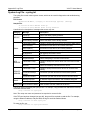
14-pin Connector Pinout
Pin
Description
Vin+
Power Supply VDC+
9-28 VDC for model X-310-I and X-310-24I
DO NOT EXCEED MAXIMUM POWER SUPPLY
VOLTAGE.
Vin-
VDC- (Ground) power supply input.
1NO
Relay 1 Normally Open Contact
2NO
Relay 2 Normally Open Contact
3NO
Relay 3 Normally Open Contact
4NO
Relay 4 Normally Open Contact
C
Relay 1,2,3, and 4 Common Contact
In1+
Positive side of the digital input 1.
In2+
Positive side of the digital input 2.
In3+
Positive side of the digital input 3.
In4+
Positive side of the digital input 4.
Gnd
Ground connection for 5VDC output, and optically isolated
inputs.
Data
Temperature/Humidity Data Input. Data connection for the
digital temperature and humidity sensors (1-Wire bus).
+5V Out
This output voltage is used to provide power for the digital
temperature/humidity sensors.
2.2.1 Power Supply Connection
X-310™ requires power for its internal logic circuits. Connect a 9-28 VDC power supply to the Vin+ and
Vin- terminals. Note that a regulated power supply is recommended. Verify that the power supply is rated
for the operating current of X-310™ (See Appendix H: Specifications for current requirements.)
Multiple X-310™ units may be connected to a single power supply by connecting the power supply input
terminals in parallel. The power supply must have a high enough current rating to power all units
connected. (See Appendix H: Specifications for current requirements.)
Xytronix Research & Design, Inc.
Page 17
Installation and Setup
X-310™ Users Manual
2.2.2 Relay Connection
The relay contacts are internally connected directly to the terminal connector. A Normally Open contact
is provided for each relay. All relays share the same Common contact. The relay contacts may be wired
in series with the power source for the load (device to be controlled) as long as the load does not exceed
the maximum current and voltage rating of the relay contacts. When connecting multiple relays, make
sure the common for all loads can be connected together without causing damage or short circuit.
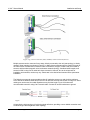
For loads greater than 1 Amp, an external interposer relay should be used. The illustration below (Figure
2.2a) shows how a 20-Amp motor can be controlled using an external relay. In the example, the X-310™
controls the external relay and the external relay controls the load.
Figure 2.2a—External Relay Connections / Figure 2.2b-High Side Switch Wiring
Page 18
Xytronix Research & Design, Inc.
X-310™ Users Manual
Installation and Setup
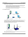
When mechanical relays switch inductive loads such as motors, transformers, relays, etc., the current
will arc across the internal relay contacts each time the contacts open. Over time, this causes wear on
the relay contacts which can shorten their life span. When switching an inductive load, it is
recommended that relay contact protection devices are used. Note that the X-310™ does not provide
relay contact protection in order to provide the greatest versatility and because appropriate protection
differs for various loads. Below is an example of relay contact protection for a DC circuit (Figure 2.2c)
and an AC circuit (Figure 2.2d). For component values required to provide sufficient contact protection
for your application, refer to appropriate references.
Figure 2.2c—DC Contact Protection
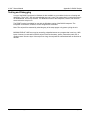
Figure 2.2d—AC Contact Protection
Xytronix Research & Design, Inc.
Page 19
Installation and Setup
X-310™ Users Manual
2.2.3 Digital Input Connections
The digital inputs can be used to control the internal relays, control remote relays (over the network), or
simply to monitor the state of a discrete device. To use these inputs, connect a DC control voltage
directly to the input and ground, and set up the function of the input using the configuration pages. A
current limiting resistor is provided internally, so no external resistors are required as long as the
maximum input voltage is not exceeded. If an AC signal, or a signal greater than the rated input voltage
needs to be detected by the X-310™, use a signal conditioner to convert the signal to a DC signal within
the input range. With the X-310, the digital inputs are not isolated and share a common ground with the
power connection.
Connecting "dry contacts" to the digital inputs:
Figure 2.2e illustrates how a dry contact switch can be connected to the input (or inputs) of the X-310™.
One side of the contact is connected to Vout, and the other side is connected to In+. When the contact is
closed, it applies 5V to the input terminals.
Figure 2.2e–Connecting Dry Contacts to X-310™
Connecting voltages to the digital inputs:
AC Inputs:
If an AC signal voltage needs to be detected, use a signal conditioner to convert the AC signal to a DC
voltage within the input range. An AC signal conditioner can be made using a diode (or bridge rectifier)
and a capacitor. Prepackaged signal converters are available as accessories at industrial automation
distributors. A simple voltage converter module manufactured by www.redlion.net is shown below. These
are available in two input voltage ranges that cover the spectrum from 4-270VAC/DC. These devices
have a MOSFET output (solid state DC contact closure) which is compatible with the X-310 input. The
converter module accepts AC (50/60 Hz) or DC voltages at input cycles up to 30 Hz. The converter
provides isolation between the input and output using an opto-isolator. You must provide a voltage
source for the input of the X-310 as shown in the example below:
Page 20
Xytronix Research & Design, Inc.
X-310™ Users Manual
Installation and Setup
DC Inputs:
With DC inputs, no external components are required as long as the maximum input voltage is not
exceeded (See Specifications). A DC voltage can be reduced with an external resistor of the appropriate
value and power rating to reduce the input current.
The formulas to calculate external resistor values are provided below:
X-310-I and X-310-E models with a 4-12VDC input range have an internal 680 ohm resistor. The forward
voltage drop of the photo-coupler is approximately 1.2V and works well with an input current of 10mA.
R =( (Vin-1.2)/0.01)-680
Where:
•
R = External resistor value required
•
Vin = Desired input voltage
•
1.2V = forward voltage drop of the LED in the photo coupler
•
.01A = workable LED current
•
680ohm = Internal resistor
For example:
To connect a 24VDC signal voltage to the X-310™ with a 4-12VDC input range:
R = ((24-1.2)/0.01)-680 = 1600 Ohms (use a 1600 ohm resistor)
Check the power dissipated by the resistor:
P = I x I x R, The resistor must be at least .01 x .01 x 1600 = 0.16 Watts, so use a 1/2
Watt resistor
Xytronix Research & Design, Inc.
Page 21
Installation and Setup
X-310™ Users Manual
X-310-24I with a 11-26VDC input range have an internal 3K ohm resistor. The forward voltage drop of
the photo-coupler is approximately 1.2V and works well with an input current of 10mA.
R =( (Vin-1.2)/0.01)-3000
Where:
•
R = External resistor value required
•
Vin = Desired input voltage
•
1.2V = forward voltage drop of the LED in the photo coupler
•
.01A = workable LED current
•
3000ohm = Internal resistor
For example:
To connect a 48VDC signal voltage to the X-310™ with a 11-26VDC input range:
R = ((48-1.2)/0.01)-3000 = 1680 Ohms (use a 1600 ohm resistor)
Check the power dissipated by the resistor:
P = I x I x R, The resistor must be at least .01 x .01 x 1600 = 0.16 Watts, so use a 1/2
Watt resistor
2.2.4 Temperature/Humidity Sensor Connection
Temperature or humidity sensors can be used for monitoring environmental conditions. The digital
sensors use a one-wire data bus, which allows up to four sensors to share the same terminals (+5V,
Ground, Data). Every sensor on the one-wire bus is assigned a unique serial number when it is
manufactured. That number is used to address the device during communication.
The sensors have three wires; the wire color is show in the table below.
Sensor Wire Color Connection
Figure 2.2f - Temperature Sensor
Page 22
Red
5V Out
Black
Gnd
Blue, White, Yellow Data
Xytronix Research & Design, Inc.
X-310™ Users Manual
Installation and Setup
Figure 2.2g - Direct Connection (Star) and Daisy Chain Connection(Linear)
Multiple sensors can be connected in two ways: directly connected to the unit (star topology) or “daisy
chained” (linear topology) as shown in Figure 2.2g. Many factors will determine the maximum length of
the cable. Some of these factors include, but are not limited to, the type of cable used, the number of
sensors, ambient electromagnetic noise, and sensor network topology. Combined cable lengths to all
sensors of 600 ft using Cat 5e cable have been successful. However, due to the uniqueness of
installation environments, results may vary. Please test in the desired environment before permanent
installation.
The following are general recommendations that will maximize sensor runs and minimize problems.
Cat 5 and Cat 5e network cable has proven to be an effective and low-cost solution for long runs. Other
cable types can be used, but cable capacitance may limit the length. Figure 2.2h shows the
recommended connection using Cat 5 network cable. Connect all unused conductors to ground.
Figure 2.2h - Recommended connection using Cat 5 cable
A linear (daisy chain) topology will minimize signal reflections, providing a more reliable connection and
will allow longer cable length than a star topology.
Xytronix Research & Design, Inc.
Page 23
Installation and Setup
X-310™ Users Manual
Appropriate strain relief should be used at the X-310™ and other connections that may be subjected to
vibration, movement, or repeated handling.
•
•
•
Avoid sensor runs adjacent to industrial equipment power cables. These cables can have high
voltage spikes that may induce noise on the sensor signals. Similarly, avoid running sensor
cables near any radio transmission antennas or coaxial feed-lines.
Protect any electrical connections with appropriate weather shielding.
Due to the broad range of applications and environments where the X-310™ may be employed,
successful installations of long sensor runs may vary significantly.
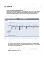
2.2.5 Network Connection
Figure 2.2i - Network Connection
Connect the Ethernet port to a 10 Base-T or 10/100 Base-T Ethernet connection. This typically connects
to an Ethernet hub, switch, or router. For configuration, X-310™ may be connected directly to the
Ethernet port on a computer using a “crossover” cable. Otherwise, for connection through a hub or
router, a standard “straight-through” cable should be used. X-310™ can be used on a wireless network
by connecting through an Ethernet bridge or a wireless router.
Figure 2.2j - Wireless Connection
Note: The wireless Ethernet bridge or router must be properly configured for the wireless network. Refer
to the installation instructions for the wireless device.
Page 24
Xytronix Research & Design, Inc.
X-310™ Users Manual
Installation and Setup
2.3 Establishing Communications for Setup
In order to configure X-310™ with the built-in web browser interface, the X-310™ and computer must be
addressed on the same network. This can be done by one of two methods:
Method 1 – Assign a temporary IP address to the X-310™ to work on an existing network.
-orMethod 2 – Temporarily change the IP address of a connected computer to the match the default IP
address used by the X-310™.
Note: If multiple ControlByWeb™ products are used on the same network, install one at a time and set
the IP address of each unit before connecting the next unit to the network. This avoids having multiple
devices on the network with the same factory default IP address at the same time. If this approach is
used, be sure to clear the arp cache after disconnecting each unit (arp -d).
2.3.1 Method 1: Assign a Temporary IP address to X-310™
This option is used to TEMPORARILY assign an IP address to X-310™ without the need to change the
IP address of the configuration computer. X-310™ will use this IP address as long as power is
maintained. Once power is lost, X-310™ will use the IP address assigned in the setup page and not the
temporary address assigned here.
Make sure that X-310™ and the configuration computer are connected to the same network.
This will not work through routers or gateways.
Microsoft Windows Instructions
1. Open a Command Prompt (select START, then RUN, then type “cmd”).
Note: For Vista, the Command Prompt should be run as administrator (select Start, then type “cmd”
and right click on “cmd” and select “Run as administrator”).
2. Type:
arp -s {new IP address} {serial number of X-310™ }
Note: IP address format is xxx.xxx.xxx.xxx. The serial number can be found on a label on the
module board. The format is ss-ss-ss-ss-ss-ss.
For example, to set X-310™ (with serial number 00-0C-C8-01-00-01 ) to 10.10.10.40 the following
command would be used:
arp -s 10.10.10.40 00-0c-c8-01-00-01
3. Next, type:
ping -l 102 {new IP address}
For example, if the new IP address is 10.10.10.40, the following command would be used:
ping -l 102 10.10.10.40
4. Proceed with X-310™ setup in section 2.4.
Once setup is complete, it may be necessary to clear the 'arp' cache to configure additional
WebRelays. This is necessary because each unit has the same default IP address, but a different
unit serial number (MAC address). Clearing the arp table can be done by typing arp -d in the
command prompt window.
Xytronix Research & Design, Inc.
Page 25
Installation and Setup
X-310™ Users Manual
Linux/Unix Instructions
1. Open a terminal and change to root user (su -, then enter root password).
2. Type:
arp -s {new IP address} {serial number of X-310™ }
Note: IP address format is xxx.xxx.xxx.xxx. The serial number can be found on a label on the
module board. The format is ss:ss:ss:ss:ss:ss.
For example, to set X-310™ (with serial number 00-0C-C8-01-00-01 ) to 10.10.10.40 the following
command would be used:
arp -s 10.10.10.40 00:0c:c8:01:00:01
3. Next, type:
ping -s 102 {new IP address}
For example, if the new IP address is 10.10.10.40, the following command would be used:
ping -s 102 10.10.10.40
4. Proceed with X-310™ setup in section 2.4.
Once setup is complete, it may be necessary to clear the 'arp' cache to configure additional
WebRelays. This is necessary because each unit has the same default IP address, but a different
unit serial number (MAC address). Clearing the arp table can be done by typing sudo arp -d -a
in the command prompt window.
Mac OS X Instructions
1. Open a terminal.
Note: The terminal is in the “Utilities” directory, which is in the “Applications” directory.
2. Type:
sudo arp -s {new IP address} {serial number of X-310™ }
Administrator password may be required.
Note: IP address format is xxx.xxx.xxx.xxx. The serial number can be found on the label on the
module board. The format is ss:ss:ss:ss:ss:ss.
For example, to set a X-310™ (with serial number 00-0C-C8-01-00-01 ) to 10.10.10.40 the following
command would be used:
sudo arp -s 10.10.10.40 00:0c:c8:01:00:01
3. Next, type:
ping -s 102 {new IP address}
For example, if the new IP address is 10.10.10.40, the following command would be used:
ping -s 102 10.10.10.40
4. Proceed with X-310™ setup in section 2.4.
Once setup is complete, it may be necessary to clear the 'arp' cache to configure additional WebRelays.
This is necessary because each unit has the same default IP address, but a different unit serial number
(MAC address). Clearing the arp table can be done by typing sudo arp -d -a in the command prompt
window.
Page 26
Xytronix Research & Design, Inc.
X-310™ Users Manual
Installation and Setup
2.3.2 Method 2: Assign a Temporary IP Address to the Configuration Computer
If the first option above is not used, you can use this option to communicate with the X-310™. By
default, X-310™ comes from the factory with an IP address of 192.168.1.2. Communication with the
X-310™ may be established by assigning an IP address to the configuration computer such that it is on
the same network as X-310™ (for example, the configuration computer could be assigned to
192.168.1.50)
The following example is for those running the Windows operating system:
1. Windows XP – Open the control panel by clicking on the start menu
and then on Control Panel.
Windows Vista/7 – Select the Windows Icon (Start Menu) and enter
ncpa.cpl into the search bar and press Enter (Figure 2.3a).
Figure 2.3a- Vista/7 Start
Menu
Note: The control panel
shown (Figure 2.3b) is in
“Classic View.” If the
control panel is in
“Category View,” select
the “Classic View” option
before proceeding.
Figure 2.3b- Control Panel
Xytronix Research & Design, Inc.
Page 27
Installation and Setup
X-310™ Users Manual
2. Double click on the
icon labeled Network
Connections. The
Network
Connections window
will open (Figure
2.3c).
Figure 2.3c- Network Connection
3. Right click on the icon labeled Local Area
Connection. In the menu that follows, select the
option at the bottom of the menu labeled Properties.
The Local Area Connection Properties window will
appear (Figure 2.3d).
Figure 2.3d- Local Area Connection
Page 28
Xytronix Research & Design, Inc.
X-310™ Users Manual
Installation and Setup
4. In the Local Area Connection Properties window in
the Connection Uses box, scroll down and
highlight “Internet Protocol (TCP/IP).” Click the
button labeled “Properties.” The “Internet Protocol
(TCP/IP)” Properties menu appears (Figure 2.3e).
Note: If “Use the following IP address” is already
selected, the computer has been setup with a
static IP address. Record these values so that the
IP address of the computer can be restored once
the IP address of the X-310™ has been
successfully changed.
5. Select the radio button labeled "Use the following
IP address" and type in the IP address:
192.168.1.50
6. Type in the subnet mask:
255.255.255.0
No need to change the default gateway field. Click
OK to accept the new settings.
7. Open the setup pages as described in section 2.4. Figure 2.3e- TCP/IP Properties
If the setup pages are not accessible, verify that X310™ is powered on and that the LINK light is illuminated. Check all network connections and
settings.
Another way to check communications is to ping X-310™ from the command prompt by typing ping
{X-310™ IP address}.
Xytronix Research & Design, Inc.
Page 29
Installation and Setup
X-310™ Users Manual
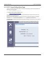
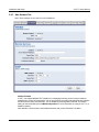
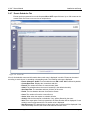
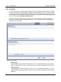
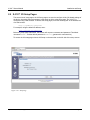
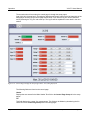
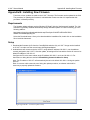
2.4 X-310™ General Settings Setup Pages
X-310™ is configured using a web browser. To access the setup pages, enter the following URL in the
address bar of a web browser:
http://{ipaddress}/setup.html
For example, using the default IP address, enter:
http://192.168.1.2/setup.html
The setup pages are divided into two sections: General Settings and I/O Setup. A third section is for
monitoring and controlling the device.
Before any setup page submission, the browser will request a username and password. The default
username is admin and the default password is webrelay (password is case sensitive).
To access the general settings setup pages choose General Settings on the menu bar on the left side of
the setup screen.
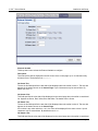
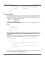
Figure 2.4a - Main Tab
Page 30
Xytronix Research & Design, Inc.
X-310™ Users Manual
Installation and Setup
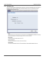
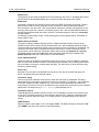
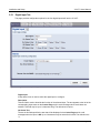
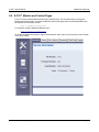
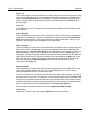
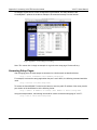
2.4.1 Information Tab
This is the initial page that is displayed when setup.html is entered into the address bar of the browser. It
displays the part number, firmware revision, and serial number of the unit. It also allows the user to
select the desired temperature units.
Figure 2.4b- Main Tab
Units
This allows the user to select between the temperature units of Fahrenheit and Celsius. All settings
entered and displayed on subsequent pages will be in the units selected.
Part Number
This displays the full model number of X-310™.
Firmware Revision
This is the current product revision of the unit's firmware.
Serial Number
This is the serial number of this unit. The serial number is also the MAC address of the unit.
Xytronix Research & Design, Inc.
Page 31
Installation and Setup
X-310™ Users Manual
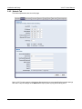
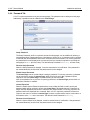
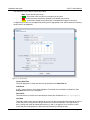
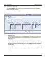
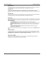
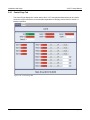
2.4.2 Network Tab
The network parameters are set on this page.
Figure 2.4c - Network Tab
Note: X-310™ must be power-cycled (power disconnected, then reconnected) before network settings
take effect. Only the settings on the Network tab require power-cycling before taking effect.
Page 32
Xytronix Research & Design, Inc.
X-310™ Users Manual
Installation and Setup
Use DHCP
This option allows DHCP to be enabled or disabled. If this option is set to Yes, X-310™ will wait for
an IP address from a DHCP server each time it is powered. The default setting is No (this is
recommended for most installations). If DHCP is set to Yes, the Network page must be submitted
and X-310™ must be rebooted before an IP address will be assigned. Once X-310™ is assigned an
IP address by the DHCP, the new IP address can be found through the list of clients kept by the
DHCP server. For most instances, the DHCP server is in the local gateway or router.
Brief Notes About DHCP
All devices on an IP network require an IP address. This is a unique address that identifies each
device on the network. DHCP (Dynamic Host Control Protocol) is a mechanism that automatically
assigns an IP address to a computer (or other devices) when it is connected to a network. This
eliminates the need to manually enter the IP address. When a computer is connected to the
network, another device on the network called a DHCP server detects the presence of the computer
and dynamically assigns the IP address to that computer. On many small networks, the DHCP
server is built into the router.
DHCP works well for "client" devices such as computers, but is not ideal for servers. This is because
servers usually don't initiate communications with other devices, but rather they wait for a request
from "clients." To make this request, the client must know the IP address of the server. If a server
gets its IP address dynamically, the IP address may not always be the same so client devices may
not be able to find the server. For this reason, servers usually use an IP address that is fixed and
does not change. X-310™ is a server and manual IP address assignment is usually recommended.
IP Address
Enter the IP address for X-310™ in this field. The IP address is specific to the network where X310™ will be installed, and must be obtained from the network administrator. For more information
on IP addresses and remotely accessing X-310™ over the Internet, see Appendix C: Accessing X310™ Remotely Over the Internet. The default setting for this field is 192.168.1.2.
Subnet Mask
The subnet mask defines the size of the local network. This can be obtained from the network
administrator. For additional information about sub-netting and IP networking, many tutorials are
available on the Internet. The default setting for this field is 255.255.255.0.
Gateway
This specifies the IP address of the gateway router. This can be obtained from the network
administrator. The default setting for this field is 192.168.1.1.
Preferred DNS Server
The IP address of the Primary DNS server is specified here. When DNS services are required, this
is the address that will be used. The default setting for this field is 192.168.1.1.
This field is only required when the following options are used:
- Remote Services (when server is specified by name and not IP address).
- Sync time clock with remote NTP server (when server name is specified by name and
not IP address).
- Mail Server (when server name is specified by name and not IP address).
Alternate DNS Server
This field is used to specify the IP address of a Secondary DNS server. This is used when X-310™
requires DNS services and the preferred DNS server is not available. The default setting for this field
is 192.168.1.1.
Xytronix Research & Design, Inc.
Page 33
Installation and Setup
X-310™ Users Manual
HTTP Port
The TCP port used for HTTP communications (web browser, xml, get commands) with X-310™ is
specified here. The default setting for this field is 80, which is the standard HTTP port. It is
recommended that the port be left unchanged unless the user has an understanding of TCP/IP and
ports. For more information on TCP ports and IP addressing see Appendix C: Accessing X-310™
Remotely Over the Internet.
Speed
This option sets the data rate (clock rate) of the Ethernet port. Either 10 Mbps or 100 Mbps can be
selected. The 100 Mbps option offers faster communications but the amount of data to and from X310™ is so small that users will not likely notice much (if any) difference. When the X-310™ is set
to 10 Mbps, it draws less power and runs a little cooler, which may translate into a longer product
life. The default setting for this field is 10 Mbps.
IT IS RECOMMENDED THAT THIS SETTING BE LEFT AT 10 Mbps UNLESS THE USER HAS A
SPECIFIC REASON TO USE 100 Mbps.
Mode
This option allows the Ethernet port to be set to Half Duplex or Full Duplex. Legacy Ethernet
operates in Half Duplex mode which means that devices can either send data or receive data, but
not both at the same time. Full Duplex means that devices can send and receive data at the same
time. The default setting for this field is Half Duplex.
Email Server Name/IP (SMTP)
The name of the SMTP (Simple Mail Transfer Protocol) mail server (for example mail.example.com)
or the IP address of the mail server (for example 192.10.10.10) should be entered in this field. There
is no default setting for this field.
Note: If the server name is entered and not the IP address, the address of a DNS server will be
required in the DNS field.
Email Server Port
This field is used to specify the SMTP Mail Server Port. The default setting is 25, which is the
standard SMTP port.
User Name (If Required)
If the SMTP mail server requires authentication, the user name must be entered here. There is no
default setting for this field.
Password (If Required)
If the SMTP mail server requires authentication, the password must be entered here. There is no
default setting for this field.
Return Email
X-310™ will not receive email messages, but when X-310™ sends email messages, it must include
a return email address. This field is used to specify the return email address. Note that although X310™ will send email messages with any email address specified in this field, some email filters
(spam filters) will not allow messages through that include an invalid email address. There is no
default setting for this field.
Email 1 to Email 3
Enter the email addresses of up to three recipients for alarm messages in these fields. There are no
default settings for these fields.
Email Message
Choose either “Control Page Content” or “Trigger Only” email formats. When “Control Page Content”
is selected, all visible fields in the control page will be included in the email message to be sent out;
Page 34
Xytronix Research & Design, Inc.
X-310™ Users Manual
Installation and Setup
however if “Trigger Only” is selected, the email content will only be a brief description of what
triggered the email message.
Remote Reboot
To cause the device to reboot, the following command can be entered into the address bar of the
browser: http://192.168.1.2/networkSetup.srv?rbt=1 The username and password will be requested
before the reboot will occur, so that only administrators of the device can cause the reboot.
MTU Setting
To change the MTU, manually enter the advSetup.html (case sensitive) page into the address bar.
(http://192.168.1.2/advSetup.html). This new setup page will have a text box that will allow the MTU
to be changed. The valid range is 256 to 1476 bytes. MTU is a network parameter that stands for
Maximum Transmission Unit. This defines the max size, in bytes, of the TCP packets sent out from
the device. This normally can be left alone, but there are some circumstances where it might be
beneficial to change it. One of these circumstances is when the device is to be used over a VPN
(virtual private network). VPN's add extra information to TCP packets, if the new packets are too big
to physically travel across the network (greater than about 1500 bytes) then the packets will be split
up. This causes problems for some firewalls and those firewalls will just discard the packets. To fix
this, the MTU can be adjusted until the TCP packets do not get split up.
Xytronix Research & Design, Inc.
Page 35
Installation and Setup
X-310™ Users Manual
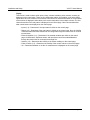
2.4.3 Adv. Network Tab
Note: These settings are not used for most installations.
Figure 2.4d - Advanced Network Tab
Modbus Enabled
X-310™ can support Modbus/TCP. Modbus is a messaging structure protocol used in industrial
manufacturing control and automation. It is an open protocol and offers interoperability with software
and devices from other manufacturers. This is enabled by selecting Yes in this field. The default
setting for this field is No. (See 3.4 Modbus Operation for more information on using X-310™ on a
Modbus network.)
Note: Modbus communications are disabled whenever the Control Password is enabled.
Page 36
Xytronix Research & Design, Inc.
X-310™ Users Manual
Installation and Setup
Modbus Port
This specifies the port used for Modbus/TCP communications with X-310™. By default this is set to
port 502 which is the standard Modbus port. It can be set within the range of 0 to 65535.
Endianness
32-bit data is treated as two individual 16-bit words using IEEE 754 floating point format. Floating
point format is used for sensor, and pulse counter as well as for setting output pulse duration.
If the checkbox is set, the X-310™ will use big-endian architecture, and the most significant 16-bit
word (big end) is sent first. If the box is cleared, then the X-310™ will use little-endian architecture,
and the least significant word (little end) is sent first. The default setting for this box is unchecked,
use little-endian.
For example, in little-endian format, a 32-bit floating point number represented by '1234 ABCD' is
sent as 'ABCD 1234'.
Remote Services Enabled
This option enables or disables Remote Services. If Yes is selected, Remote Services will be
enabled as soon as the submit button is pressed and X-310™ will immediately attempt to make a
connection with the remote server (power cycle not required). Once a connection is established, the
connection will remain until it is disconnected by the remote server. Proper connection with the
remote server can be verified by viewing the system status log file (see Appendix D: Log Files).
The default setting for this field is No. Most users should leave this setting at its default. (See
Remote Services at the end of this section for more information.)
Server Name/IP Address
Specify the name or IP address of the Remote Services server here. If the IP address is specified,
enter it in this format aaa.bbb.ccc.ddd. For numbers that are less than 100, preceding zeros should
not be included (for example, enter 80 rather than 080). This field can be up to 40 characters long
and has no default setting.
Server Port
Enter the TCP port used for the Remote Services server. This can be set within the range of 065535. The default setting for this field is 8000.
Connection String
This text is sent to the Remote Services server when the connection is established. This string
should include any information required by the server at connection. For example, it may include an
ID number, customer number, password, etc. The format is entirely dependent upon the server
requirements. This field can be up to 80 characters long. Default text is provided only as an example
placeholder. The default text is [<Serial Number>]:ControlByWeb,X-310.
Connection Interval
This field specifies the periodic interval in which X-310™ attempts to connect to the remote server,
or if X-310™ is already connected, it is the interval in which X-310™ sends the connection string.
This field can be set within the range of 1 to 34452 minutes. The default setting for this field is 1
minute.
SNMP Enabled
When this option is set to Yes, X-310™ will support SNMP. The default setting for this option is No.
(See SNMP at the end of this section for more information.)
Xytronix Research & Design, Inc.
Page 37
Installation and Setup
X-310™ Users Manual
SNMP Server IP
When SNMP is used, this field is used to specify the IP address of the SNMP manager. The default
setting for this field is 192.168.1.25.
SNMP Server Port
When SNMP is used, this field is used to specify the SNMP port that X-310™ listens on. The default
setting for this field is 161.
SNMP Trap Port
When SNMP is used, this field is used to specify the SNMP Trap port of the SNMP manager. The
default setting for this field is 162.
Remote Services
Remote Services initiates an outgoing connection to a server at a remote location. This can be used in
an environment where a web server on the Internet provides a custom web page to X-310™ and other
ControlByWeb products. Users access X-310™ through the web server rather than communicating
directly with it. This method is sometimes referred to as “web services” and allows programmers to
create powerful, custom web pages to multiple devices using the web programming languages of their
choice.
Remote Services initiates the connection to the external web server (rather than the web server initiating
communications to X-310™). This has two main benefits. First, the web server does not need to know
the IP address of X-310™. This means that X-310™ can get its IP address dynamically from a DHCP
server, simplifying the installation. Second, since the connection from X-310™ is outgoing, rather than
incoming, the local router on the network where X-310™ resides doesn't need to be configured to
forward sockets. This also simplifies the installation. Since the router configuration is not modified, the
risk of compromising security on the local network is eliminated. For more information about the Remote
Services see Appendix E: External Server and Remote Services.
SNMP
Simple Network Management Protocol (SNMP) is used to manage and administer network devices. X310™ supports SNMP V1.0 and can be configured here. Using SNMP, the I/O states of X-310™ can be
read as well as some basic information about the device. See Appendix F: SNMP Requests for
information about how to request information from X-310™ using an SNMP manager, as well as where
to find MIB files for X-310™.
Note: The read and write community strings used for SNMP are actually the Control Password found on
the Password setup tab (see Section 2.4.4). If the Control Password is disabled, then X-310™ does not
check for the community string when issued a Get or GetNext request from the SNMP manager.
Page 38
Xytronix Research & Design, Inc.
X-310™ Users Manual
Installation and Setup
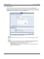
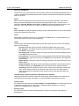
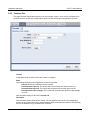
2.4.4 Password Tab
X-310™ requires a password to log into the setup pages. The password can be changed on this page.
Additionally, a password can be enabled for the Control Page.
Figure 2.4e - Password Tab
Setup Password
The Setup Password, which is required to access the setup pages, can be modified by entering a
new password here. Passwords that are 8 characters or longer (up to 13 characters can be entered
in this field) with both alphabetic and numeric characters are recommended. For security purposes,
the password will not be displayed as it is entered. Note: the username required for accessing the
setup pages is admin (all lower case). The default Setup Password is webrelay (all lower case).
Re-enter Setup Password
When the Setup Password is changed, it must be entered twice for verification. If the password is
not entered identically in both fields, the password will not be changed.
Enable Control Password
The Control Page can be viewed without entering a password. For security purposes, a password
can be required to access the Control Page. When this field is set to Yes, a password will be
required to view the Control Page. The default setting for this field is No.
Note: Since Modbus has no provision for passing passwords, the Control Page password will not
take effect if Modbus is enabled.
Control Password
When the Enable Control Password option above is set to Yes, this field is used to specify the
password which will be required to access the Control Page. Passwords that are 8 characters or
longer with both alphabetic and numeric characters are recommended. For security purposes, the
password will not be displayed as it is entered. Note: X-310™ requires a password, but does not
require a user name to access the Control Page. However, some browsers require a user name. In
this instance enter none as the user name. The default Control Password is webrelay.
Re-enter Control Password
When the Control Password is changed, it must be entered twice for verification. If the password is
not entered identically in both fields, the password will not be changed.
Xytronix Research & Design, Inc.
Page 39
Installation and Setup
X-310™ Users Manual
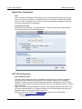
2.4.5 Date/Time Tab
X-310™ uses the time of day for scheduled events, such as turning the Outputs ON or OFF at
scheduled times and for logging (a time stamp is included with each logged event). The time is stored
and displayed in 24-hour time format. X-310™ has a capacitor-backed real-time-clock circuit that will
keep track of time for several days in the event of a power failure.
Figure 2.4f - Date/Time Tab - Set Time Manually
Date/Time
This is the current date and time stored in X-310™. The time is stored and displayed in 24-hour
format.
Set Time
This drop-down list offers two options for setting the time: Manually or Sync with NTP server.
The options that follow this field will change based upon how this option is set.
- Manually requires the user to enter the time and date.
- Sync with NTP server allows the user to set the clock automatically by using an NTP
(Network Time Protocol) server.
Page 40
Xytronix Research & Design, Inc.
X-310™ Users Manual
Installation and Setup
Manual Time Configuration
Date
The current date is entered by first selecting the correct month and year,using the left and right
arrows at the top of the calender. The single arrows(< and >) change the month and the double
arrows (<< and >>) change the year. Once the current month and year are displayed, select the
correct day, which will then be highlighted.
Time (24 Hour Format)
Enter the time as HH:MM:SS. (HH represents hours in 24-hour format [00-23], MM represents
minutes [00-59], SS represents seconds [00-59].)
Figure 2.4g - Date/Time Tab - Sync with NTP Server
NTP Time Configuration
Server Name/IP Address
This field is used to specify the name or IP address of the NTP server. If a name is specified, a
working DNS server address must be entered into the Network settings. If the IP address is
specified, it should be entered in the following format aaa.bbb.ccc.ddd where each of the letters
represents a number between 0 and 255. This field can be up to 40 characters. There is no default
value for this field.
Many NTP Internet servers are available. In addition, many desktop computers will function as an
NTP server (both Mac and PC). If a desktop computer is used, firewall settings may need to be
adjusted to allow for NTP communications on port 123.
Public NTP servers can be found at www.pool.ntp.org. Some of these are listed below.
US Servers (http://www.pool.ntp.org/zone/us):
0.us.pool.ntp.org
Xytronix Research & Design, Inc.
Page 41
Installation and Setup
X-310™ Users Manual
1.us.pool.ntp.org
2.us.pool.ntp.org
3.us.pool.ntp.org
North America (http://www.pool.ntp.org/zone/north-america):
0.north-america.pool.ntp.org
1.north-america.pool.ntp.org
2.north-america.pool.ntp.org
3.north-america.pool.ntp.org
Europe (http://www.pool.ntp.org/zone/europe):
0.europe.pool.ntp.org
1.europe.pool.ntp.org
2.europe.pool.ntp.org
3.europe.pool.ntp.org
Australia (http://www.pool.ntp.org/zone/au):
0.au.pool.ntp.org
1.au.pool.ntp.org
2.au.pool.ntp.org
3.au.pool.ntp.org
South America (http://www.pool.ntp.org/zone/south-america):
0.south-america.pool.ntp.org
1.south-america.pool.ntp.org
2.south-america.pool.ntp.org
3.south-america.pool.ntp.org
Africa (http://www.pool.ntp.org/zone/africa):
1.africa.pool.ntp.org
1.pool.ntp.org
3.pool.ntp.org
Sync With Server
This option allows the user to specify how often the time on X-310™ will be synchronized with the
time server. When the submit button on this page is pressed, X-310™ will immediately synchronize
with the time server. If Daily, Weekly, or Monthly options are selected, X-310™ will thereafter resynchronize with the time server at the period interval specified starting at 12:00 AM (00:00).
The exact time the NTP Request occurs is 12:00 AM (00:00) plus the minute equivalent of the last
two digits in the models serial number. For example, if the last two digits in the model's serial
number were -09, the NTP Request will occur 9 minutes after 12:00 AM. The default value of this
setting is Once (the unit will immediately sync with the NTP server, but will not automatically sync
again).
Sync on Power Up
When this option is set to Yes, X-310™ will be synchronized with the time server each time it is
powered.
Note: If X-310™ will lose power on a frequent basis, it may be beneficial to set this option to No;
some servers are configured to dis-allow access from client devices that excessively request their
services. The default value of this setting is No.
UTC Offset
Time servers return the current time in Universal Time (GMT). It is common for many servers and
data loggers to use GMT as their official time, even when they are not located within the GMT time
Page 42
Xytronix Research & Design, Inc.
X-310™ Users Manual
Installation and Setup
zone. The default value for this field is -7 (Mountain Standard Time). For convenience, the time can
be converted to local standard time by entering the offset here. This manual cannot include the UTC
Offset for all parts of the world, but the offset for GMT time and the four major US Time zones are
listed here.
GMT Time: 0
Eastern Standard Time: -5
Central Standard Time: -6
Mountain Standard Time: -7
Pacific Standard Time: -8
Daylight Savings
In many parts of the United States and in some other countries, the time is shifted forward by one
hour during the summer months. This is an effort to conserve energy by making the daylight last
longer into the evening hours. If this option is set to Yes, the time on X-310™ will automatically be
shifted forward by one hour between the hours of 12:00 AM – 5:00 PM on the Daylight Savings Start
date set below, and it will shift back to standard time between the hours of 12:00 AM – 5:00 PM on
the Daylight Savings End date set below. The time change is made at a random time within the
previously mentioned, five-hour time frame, in order to prevent several different devices from
simultaneously requesting a time and overwhelming the NTP server. The default setting is Yes.
Note: Enabling the daylight savings time adjustment, scheduled events will be adjusted for the new
time. Logged data includes a time stamp based upon the current time in the device, so it is possible
to duplicate log times in the spring and miss log times in the fall. To avoid confusion, many servers
and data loggers are set to remain on GMT time and do not shift for daylight savings.
Daylight Savings Start Day
This is the date that daylight savings will start. Note that on this date, between the hours of 12:00
AM – 5:00 PM, the current time will be shifted forward by one hour (i.e. the time will jump from 12:02
AM [00:02] to 1:02 AM [01:02]). By default this is set to the 2nd Sunday in March which is the date
used in the United States.
Daylight Savings End Day
This is the date that daylight savings will end. On this date, between the hours of 12:00 AM – 5:00
PM, the current time will be shifted backward by one hour (i.e. time will jump from 12:02 AM [00:02]
to 11:02 PM [23:02] the day before). By default this is set to the 1st Sunday in November which is
the date used in the U.S.
Xytronix Research & Design, Inc.
Page 43
Installation and Setup
X-310™ Users Manual
2.4.6 Logging Tab
X-310™ can be configured to record data such as changes in I/O state, sensor data, and events. Both
periodic and event-based logging are supported. The logged data is stored in internal nonvolatile
memory and can be retrieved by entering the command http://{X-310 IP address}/log.txt. For more
information on logging, see Appendix D: Log Files.
The log is stored in non-volatile, flash memory using a circular buffer (old date is over written). 512 kB of
memory space is reserved for logging. Log entries are composed of the following components, 8-byte
header, and 4 bytes for each log feature selected, except relays and inputs, which add two bytes
regardless of how many are logged. A log of Vin 1 (4 bytes) and 4 digital inputs (1 byte) will occupy 13
bytes per entry.
Note: Changing the log settings will erase the current log file.
Figure 2.4h - Logging Tab
Logging Enabled
When this option is set to Yes, X-310™ will record data as configured on this page. The default
setting for this option is No.
Note: This option controls data logging, but not system logging. System logging is always enabled.
Note: Logging of the Pulse Counter 1 or 2 will reduce the maximum counter rate to 10 Hz. Enabling
other options can lower this rate even more.
Start Time
If a logging interval is specified (periodic logging rather than event logging), logging will occur
relative to this start time. For example, if the start time is 01:00 and the logging rate is 6 hours,
logging will occur at 01:00, 07:00, 13:00, and 19:00. Start time is specified in 24-hour time format.
The default setting for this field is 01:00.
Page 44
Xytronix Research & Design, Inc.
X-310™ Users Manual
Installation and Setup
Logging Rate
This field is used to specify the time period of logging. A numerical value is entered into the text field,
and the unit of time is selected using the adjacent radio buttons. The range of values in this field is
1-20864. Time units are Minutes, Hours, and Days. Periodic logging can be disabled by selecting
the Event Logging Only radio button.
Logging Configuration
This section is used to select which inputs, relays, pulse counters, sensors, Vin and events get
logged and which events trigger the logging. There are five configuration tables. The first column in
each table identifies the elements to be logged . The second column is used to specify which events
can cause a log entry to be created. The last column is used to specify the Trigger Delta for the
corresponding counters and sensors.
When relays are selected as an Event Trigger, logging will occur whenever the selected relay is
turned ON or OFF. When inputs are selected as an Event Trigger, logging will occur whenever the
input state changes. When pulse counters, sensors and Vin are selected as an Event Trigger,
logging will occur whenever the input or sensor changes by the trigger delta.
The following Log/Event Trigger options are available:
- Inputs (1-4)
- Relays (1-4)
- Sensors (1-6)
- Pulse Counters (1-2)
- Vin
- Events
- XML Requests
- MODBUS Requests
- SNMP Requests
Note: Logging activity will lower the highest possible pulse counter rates.
Xytronix Research & Design, Inc.
Page 45
Installation and Setup
X-310™ Users Manual
Sensor Trigger Delta
X-310™ can be configured to log data when the count, voltage, temperature, or humidity measured
by a sensor changes by the amount specified in this field. This can be set from 1.0 to 9999 units, in
0.1 increments. The default setting for these fields is shown below.
Sensor
Trigger Delta
Counters
2
Vin
2.0 V
Temperature
2º
Humidity
2%
Filter Logged Requests
When logging is enabled for XML Requests, Modbus Requests, or SNMP Requests, the user can
filter out Reads (such as reading the Digital I/O states via an XML request) or Writes (such as
changing the output state via an XML command).
On the Control Page Setup tab, the user can specify the refresh rate of the Control Page. Each
time the page is refreshed, an XML request is sent and logged as a Read. Since the default refresh
rate is 3 seconds, the log file can get cluttered by many XML request logs. By filtering out Reads,
refresh requests will not be shown in the log. Likewise, by selecting Writes, any log created by
changing the state of the output will not be shown in the log file. The default selection is None.
Next Log Time
This field displays the next periodic log time. If logging is disabled, the next log time will indicate
"Disabled." If logging is enabled, but periodic logging is disabled (by selecting Event Logging Only)
the next log time will indicate "Event Logging Only."
Note: This information is updated only when the page is refreshed.
Page 46
Xytronix Research & Design, Inc.
X-310™ Users Manual
Installation and Setup
2.4.7 Events Scheduler Tab
Events can be programmed to turn the Outputs ON and OFF at specific times. Up to 100 events can be
created. Each event can occur one time or multiple times.
Figure 2.4i - Events Tab
A list of all scheduled events and information about each event is displayed in a table. Events can be sorted
according to each column, in ascending or descending order. The following columns are displayed:
- Events Scheduler: On/Off: Turns scheduled events ON or OFF. ON is selected by default.
- Current Date/Time: Displays the current date and time.
- Event #: The number and name of events that are listed.
- Schd #: The schedule where the event is located (0 is the default schedule).
- Start Date/Time: The start date and time (24-hour) of the event.
- Period: The time between the start of successive events.
- Count: The number of times the event will occur.
- Action: What action the outputs or schedule will take
- Act #(s): Which of the outputs or schedules, if any, will be affected by the event.
- Value: If an output pulse event is programmed, the Pulse Duration will be displayed. If a set
extVar(s) event is programmed, the new extVar value is displayed.
- Next Occurrence: The date and time of the event's next occurrence will be displayed. If the
event has already occurred, the event will be listed as “Inactive” here.
Xytronix Research & Design, Inc.
Page 47
Installation and Setup
X-310™ Users Manual
The events are color coded to indicate their status.
- Gray – Event has not been set up.
- Green – Events are active and will occur sometime in the future.
- Red – Events have been temporarily disabled by the disable event action.
- Yellow – Events have already occurred and are not scheduled to happen in the future.
Configuration of events is accomplished by clicking on the appropriate event, which causes the following
setup screen to be displayed.
Figure 2.4j - Event Setup
Current Date/Time
This field displays the current date and time as specified in the Date/Time tab.
Schedule #
X-310™ can be setup to use multiple schedules. The master event schedule is schedule 0. (See
Schedules below for more information.)
Description
Text entered here is used to name and describe each event. Default text is Event Description.
Start Date
This field is used to enter the start date of the event. The date is entered by first selecting the correct
month and year by using the left and right arrows at the top of the calender. The single arrows (<
and >) change the month and the double arrows (<< and >>) change the year. Once the current
month and year are displayed, the date should be entered by selecting the day.
Page 48
Xytronix Research & Design, Inc.
X-310™ Users Manual
Installation and Setup
Start Time (HH:MM:SS)
The start time of the event is entered in the drop down menus as HH:MM:SS (HH represents hours
in 24-hour format [00-23], MM represents minutes [00-59], SS represents seconds [00-59]). Default
setting is 00:00:00.
Period
When events are configured to occur more than one time (any entry other than 1 in the Count
below), the period field specifies the time between the beginning of events. This time can be
specified in Seconds, Minutes, Hours, Days, or Weeks by selecting the appropriate option in the
drop down menu. Default settings is 0 Days. Note that selecting 0 will disable the event.
Days
When a Period of one day is selected, the day(s) on which that event will occur can be specified by
marking the appropriate check boxes.
Count
The number of times the event will occur is specified. The default text is 0. Note that entering 0 in
this field will cause the event to occur continuously.
Action
This drop down menu specifies which action will take place when the event occurs. The following
options may be selected
- no action: When this option is selected, nothing will happen when event occurs.
- turn relay(s) on: This option causes the relay(s) specified in the Affected Relays(s) field to
turn ON when event occurs.
- turn relays(s) off: This option causes the relays(s) specified in the Affected Relays(s) field
to turn OFF when event occurs.
- pulse relays(s): This option causes the relays(s) specified in the Affected Relays(s) field to
turn ON when the event occurs, and then turn OFF after the Pulse Duration time (specified
below) expires.
- toggle relays(s): This option causes the relays(s) specified in the Affected Relay(s) field to
change states.
- change schedules: This option causes the schedule(s) specified in the Affected field to be
enabled or disabled. (See Schedules at the end of this section for more information).
- set extVar(s): External variables provide a way for scripts written in BASIC to interact with
users, and for scripts to execute as a result of event occurrences. This option sets the
extvar(s) specified in the Affected External Variables field to a specified value when the
event occurs.
Affected Relay(s), Affected Schedules, Affected External Variables
Depending on the Action selected in the Action field, another field will appear with 4 check boxes.
This field selects which relays, schedules, or external variables are affected by the action.
Pulse Duration
If the Output Action has been set to pulse output(s), the Pulse Duration is set in this field. The time
is specified in seconds and can range from 0.1 seconds to 86400 seconds in 0.1 second
increments. The default time is 1.5 seconds.
ExtVar(s) Value
If the Action has been set to the Set ExtVar(s) action, then the new value for the extVar(s) is
specified here.
Xytronix Research & Design, Inc.
Page 49
Installation and Setup
X-310™ Users Manual
Schedules
Events can be assigned to one of five schedules. The schedules are useful for creating complex events
that vary with calendar dates, such as work shift alarms. Schedule 0 is always active, it cannot be
disabled. Other schedules can be enabled and disabled by schedule events. Multiple schedules may be
active at one time. The following is an example of how schedules and events might be used.
Schedule 0 Event – Communication device is enabled daily at 8 pm and disabled at 6 am, Monday
through Friday. (The web interface could be used to disable the system for any authorized exceptions.)
Field Name
Event 1
Event 2
Application Description
Schedule #
0
0
Schedule 0 cannot be disabled by other events.
Description
SCADA ON
SCADA OFF
User description of event.
Start Date
Current Day
Current Day
Set to current or previous day.
Start Time
20:00:00
06:00:00
Start time in 24 hr format.
Period
1 Days
1 Days
Event occurs daily.
Days
M-F
M-F
Security system is disabled during work hours and
remains on over weekend.
Count
0
0
Event is always in effect, set to zero.
Action
turn output on turn output off
Security system is controlled through Output 1.
Affected
1
1
Output 1 receives the Action
Pulse Duration
n/a
n/a
The value is ignored except for a pulse action.
Schedule 1 and 2 Events – Radio transmission reports triggered at 8 am and 5 pm Monday through
Friday, during winter months but, shifts to 6 am start time during summer.
Field Name
Event 3
Event 4
Event 5
Event 6
Event 7
Event 8
Schedule #
1
1
Description
Summer AM Summer AM
Report
Report
Start Date
30 May
Start Time
0
2
2
0
End Summer Winter AM
Report
Winter AM
Report
End Winter
30 May
01 Sep
01 Sep
1 Sep
30 May
08:00:00
17:00:00
00:00:00
06:00:00
03:00:00
00:00:00
Period
1 Days
1 Days
365 Days
1 Days
1 Days
365 Days
Days
M-F
M-F
All
M-F
M-F
All
Count
0
0
0
0
0
0
Action
pulse output pulse output
change
schedules
pulse output
pulse output
change
schedules
Affected
1
1
2
1
1
1
Pulse Duration
3
3
n/a
3
3
n/a
In the above example, the Affected row applies to Outputs. When an output action is selected, or when a
change schedule action is selected. The security system example could also be changed to schedules 1
and 2, allowing for different hours of operation for summer and winter schedules. Additional lunch or
break bells could also be added to schedules 1 and 2 or added in schedules 3 and 4. Events 5 and 8
enable and disable schedules. Event 5 would enable schedule 2, and disable schedules 1,3,4. Event 8
would enable schedule 1, and disable schedules 2,3,4. Additional equipment could be controlled by
event schedules such as lighting, compressors, and magnetic door locks.
Page 50
Xytronix Research & Design, Inc.
X-310™ Users Manual
Installation and Setup
2.4.8 Script Tab
X-310™ can be used to run simple custom programs written in a language similar to BASIC. This page
is used to load and execute these programs. Before it can be loaded to the X-310™, a script must first
be written as a .txt file. The file must then be uploaded to X-310™ via the Basic Script tab (the maximum
size of script that can be uploaded to the device is 2K bytes). Information on writing a basic program for
X-310™ can be found in Appendix G: Basic Scripts.
Note: An ASCII standard text file format should be used, such as Windows Notepad, Programmer's
Notepad, vi, or other text editor that output the file as a .txt. Rich Text Format (.rtf) used by Microsoft
WordPad is NOT compatible.
Figure 2.4k - Script Tab
BASIC Script
This field displays the .txt file that is uploaded to X-310™. Text displayed in this screen cannot be
edited. In order to edit any script, it must be rewritten in the .txt file and uploaded to the unit again.
Interpreter Status
This field displays whether the program is continuing to run, has stopped or finished, or if there are
errors contained in the script. If there are errors in the script, the line on which the error occurred is
displayed.
Xytronix Research & Design, Inc.
Page 51
Installation and Setup
X-310™ Users Manual
Upload BASIC Script
This field displays the script selected to be uploaded to the device. To upload a script to X-310™,
click the 'Choose File' button, find the .txt file previously created, and select 'Open.' The location of
the file should appear in the neighboring field. To upload the script to the unit, select 'Submit.'
Run Script
This option selects whether or not the selected script will be run after it has been uploaded. The
Submit button must be clicked to run the script.
Page 52
Xytronix Research & Design, Inc.
X-310™ Users Manual
Installation and Setup
2.4.9 Control Page Setup Tab
The Control Page Setup page is used mainly to set parameters that affect the view of the Control
Page, how often it will refresh, etc.
Figure 2.4l - Control Page Setup Tab
Main Header Text
The text entered here appears at the top of the Control Page. It also appears in the header of the
email text when the email notification is used. This field can be up to 40 characters in length. The
default text is X-310.
Auto Refresh
The Auto Refresh Page option will cause the Control Page to continually update its contents by
setting a timer in the web page that causes it to be reloaded at a specified time interval. When set to
Yes, the web page will be refreshed at the time interval specified in the Refresh Rate setting. When
set to No, the web page will need to be manually refreshed to show the current status of the unit on
the control page.
Refresh Rate
When the Auto Refresh Page option is set to Yes, this field specifies the time interval in seconds that
the page will be refreshed. It can be set from 1 to 32 seconds. The default Refresh Rate is 3
seconds
Xytronix Research & Design, Inc.
Page 53
Installation and Setup
X-310™ Users Manual
Display
This section is used to select which inputs, relays, external variables, pulse counters, sensors get
displayed on the control page. There are six configuration tables. Some tables, such as the digital
inputs table, have one column of check boxes. Each check box determines whether or not the status
of the element is displayed. Other tables, such as the relays table, have multiple columns. The first
column determines if the relay status is displayed on the control page. Other columns determine
what control buttons are displayed on the control page.
- Inputs (1-4) – Determines if the input status is visible on the control page.
- Relays (1-4) – Determines if the relay status is visible on the control page. Also, the visibility
of On/Off buttons and Pulse buttons can be configured through the check boxes in columns
two and three.
- External Variables (1-4) – Determines if the external variables are visible on the control
page. On/Off buttons, Up/Down arrows, and Input boxes can all be enabled/disabled
through the check boxes in columns three through five.
- Sensors (1-6) – Determines the visibility of the sensor readings on the control page.
- Pulse Counters (1-2) – Determines the visibility of the counter values on the control page.
- Vin – Determines whether or not the Vin measurement is displayed on the control page.
Page 54
Xytronix Research & Design, Inc.
X-310™ Users Manual
Installation and Setup
2.5 X-310™ I/O Setup Pages
The second set of setup pages, the I/O Setup pages, are used to configure all the I/O related settings of
the device. Accessing these setup pages is the same as all the other setup page. The X-310™ is
configured using a web browser. To access the setup pages, enter the following URL in the address bar
of a web browser:
http://{ipaddress}/setup.html
For example, using the default IP address, enter:
http://192.168.1.2/setup.html
Before any setup page submission, the browser will request a username and password. The default
username is admin and the default password is webrelay (password is case sensitive).
To access the I/O setup pages choose I/O Setup on the menu bar on the left side of the setup screen.
Figure 2.5a - Setup Page
Xytronix Research & Design, Inc.
Page 55
Installation and Setup
X-310™ Users Manual
2.5.1 Digital Input Tab
This page provides configuration options for the four digital inputs built into the X-310™.
Figure 2.5b - Digital I/O Tab - Input Configuration
Digital Input
A drop-down menu is used to select the digital input to configure.
Description
This text field is used to describe the function of the selected input. The text appears to the left of the
corresponding input status on the Control Page, and in email messages when email alerts are
enabled. This field may be up to 9 characters long. The default text is Input #.
On Status Text
The text in this field specifies the text that will be displayed in the Control Page and in email
messages when the input is ON. Up to 9 characters may be entered in this field. The default text is
ON.
Page 56
Xytronix Research & Design, Inc.
X-310™ Users Manual
Installation and Setup
On Status Color
This field specifies the color that will be displayed on the control page when the input is considered
On. Options are Green, Red, Yellow, Blue and White. The default color is Green.
Off Status Text
The text in this field specifies the text that will be displayed in the control page and in email
messages when the input is OFF. Up to 9 characters may be entered in this field. The default text is
OFF.
Off Status Color
This field specifies the color that will be displayed on the control page when the input is considered
Off. Options are Green, Red, Yellow, Blue and White. The default color is Red.
Email Option
Simple email messages can be sent in response to input changes. This parameter is used to specify
what input changes, if any, will cause email messages to be sent. The default setting for this field is
No Email Messages.
- No Email Messages: No email notifications will be sent due to input changes.
- Send Email when input on: Email notifications will be sent when input state changes to On.
- Send Email when input off: Email notifications will be sent when input state changes to
OFF.
- Send Email when input changes state: Email notifications will be sent when input
changes state to ON or OFF.
Note: Email notification will work only if the email settings are correctly set up in the Network setup
page.
Use Email Address
If email messages are to be sent out based on input changes, these check boxes specify to which
email addresses the message will be sent. Email addresses specified on the Network setup tab will
be displayed next to each check box. By default, no boxes are checked.
Remote Service/SNMP
When this box (Send State Msg/Trap on Input Change) is checked, SNMP traps and/or State
messages will be sent whenever the input state changes.
Xytronix Research & Design, Inc.
Page 57
Installation and Setup
X-310™ Users Manual
2.5.2 Counters Tab
This page provides configuration options for the two counters. Inputs 1 and 2 can be configured to be
used as counters, counter one corresponds to input one and counter two corresponds to input two.
Figure 2.5c - Counters Tab - Input Configuration
Counter
A drop-down menu is used to select the counter to configure.
Mode
This settings determines what triggers the counter to increment.
- Counter off: No input transitions will be counted.
- Increment when input on: The counter will increment each time the input turns on.
- Increment when input off: The counter will increment each time the input turns off.
- Increment when input changes: The counter will increment each time the input changes
on or off.
Note the default setting for this field is Counter off.
Description
This text field is used to describe the counter. The text appears to the left of the corresponding
counter on the Control Page, and in email messages when email alerts are enabled. This field may
be up to 9 characters long. The default text is Count #.
Page 58
Xytronix Research & Design, Inc.
X-310™ Users Manual
Installation and Setup
Units
This text field is used to describe the units counted. The text appears to the right of the counter
reading. This field may be up to 4 charters long.
Slope (Multiplier)
The counter can be scaled to represent “real-world” units. X-310™ reads the “raw” value from each
counter, and calculates the number that represents the “real-world” measurement. This scaled value
is calculated using the following linear formula.
Scaled Value = Slope * Count + Offset
The calculated scaled value is used for trigger logs, email messages, control page, XML page, and
returned when Modbus values are read.
The “slope” in the formula above is provided by the user and is entered in this field. When both the
slope and offset are set to their default values, 1 and 0, respectively, the scaled value equals the
actual count.
When the counter is set to whole number mode, the slope multiplier is truncated, all digits to the
right of the decimal place are ignored.
Offset
The “offset” in the formula above is provided by the user and is entered in this field. The default
value for this field is 0.
Reset Counter
This button will reset the counter to zero.
Xytronix Research & Design, Inc.
Page 59
Installation and Setup
X-310™ Users Manual
2.5.3 Vin Tab
Figure 2.5d - Vin Tab - Input Configuration
This page configures how the supply voltage will be monitored.
Description
This text field is used to describe the supply voltage. By default it is set to “Vin.” The text appears to
the left of the Vin status on the Control Page. This text will also appear in email messages when
email alerts are enabled. This field may be up to 9 characters long.
Decimal Places:
This text field is used to specify the number of digits shown on the right of the decimal point on the
Page 60
Xytronix Research & Design, Inc.
X-310™ Users Manual
Installation and Setup
control page. The minimum number of decimal places shown is 0. The maximum number of decimal
places shown is 5. The default for this field is 3.
Alarm 1 Color
The selected color that will be displayed on the Control Page when Alarm 1 is reached. Options are
Green, Red, Yellow, Blue and White. The default setting is Green.
Alarm 2 Color
The selected color that will be displayed on the Control Page when Alarm 2 is reached. Options are
Green, Red, Yellow, Blue and White. The default setting is Red.
Normal Color
This field specifies the color that will be displayed on the Control Page when the Vin voltage is in a
Normal condition. Options are Green, Red, Yellow, Blue and White. The default setting is White.
Alarm 1
This setting is used to set the trigger point for an alarm condition. The number field specifies the
value at which the alarm is triggered. The High and Low radio buttons indicate whether the alarm is
triggered as a high or low alarm. A high alarm is triggered when the Scaled Value of Vin exceeds
the Alarm 1 set point. A low alarm occurs when the Scaled Value of Vin is lower than the alarm set
point.
Alarm 2
This is a second alarm trigger that works identical to Alarm 1.
Deadband
The Deadband prevents alarms from triggering excessively when the Vin measurement vacillates
around the trigger point. With high alarms, the measurement must fall below the high alarm point
minus the deadband before the high alarm will be triggered again. Likewise the deadband on the low
alarm requires the measurement to rise above the low alarm point plus the deadband before the low
alarm will be triggered again.
For example, if the deadband is set to 0.5 V, and a high alarm occurs at 13 V, the alarm will not
trigger until the temperature first drops below 12.5 V (13 V - 0.5 V).
Xytronix Research & Design, Inc.
Page 61
Installation and Setup
X-310™ Users Manual
Email Option
Simple email messages can be sent in response to alarm conditions. This parameter is used to
specify what alarm conditions, if any, will cause email messages to be sent. Email notification will
work only if email is correctly setup in the Network setup page.
-
No Email Messages: No email messages will be sent due to alarm conditions.
Send Email on Alarm 1: Email notifications will be sent due to Alarm 1 conditions.
Send Email on Alarm 2: Email notifications will be sent due to Alarm 2 conditions.
Send Email on Alarm 1 and Alarm 2: Email notifications will be sent due to Alarm 1 or
Alarm 2 conditions.
- Send Email on Alarm 1, Alarm 2, and Normal: Email notifications will be sent due to Alarm
1, Alarm 2, or when Normal conditions are regained.
Use Email Address
If email messages are to be sent based on alarm conditions, these check boxes specify to which
email addresses the message will be sent. Email address specified on the Network setup tab will be
shown next to each check box.
Remote Service/SNMP
This field specifies the action with a remote server due to an alarm condition.
- No Action: No action is taken.
- Send State Msg/Trap: An event string will be sent to the remote server.
The second drop down box specifies the conditions that will cause an alarm trigger. The following
alarm conditions are available:
- Alarm 1: The specified action occurs due to Alarm 1.
- Alarm 2: The specified action occurs due to Alarm 2.
- Alarm 1 or Alarm 2: The specified action occurs due to Alarm 1 or Alarm 2.
Page 62
Xytronix Research & Design, Inc.
X-310™ Users Manual
Installation and Setup
2.5.4 1-Wire Sensors Tab
This tab is used to configure temperature/humidity sensors and associated alarms. X-310™ will
automatically detect whether a temperature or humidity sensor is connected.
Sensor
Up to four sensors can be connected to X-310™. This drop-down list selects the sensor to be
configured. The fields below are the same for each sensor.
Figure 2.5e - Sensors Tab
Sensor Description
The text in this field appears to the left of the corresponding temperature/humidity reading on the
Control Page. This text also appears in the email status message when email is enabled. This field
can be up to 14 characters in length. The default text in this field is Sensor #.
Xytronix Research & Design, Inc.
Page 63
Installation and Setup
X-310™ Users Manual
Sensor Address
Each sensor connected to X-310™ should be associated (or assigned) to a sensor number. This
identifies the name, location, and function of the sensor. Every temperature/humidity sensor comes
from the factory with a unique, non-changeable address. When the sensors tab is selected (or the
Refresh List button is pressed), X-310™ scans the bus for sensors. The addresses of the sensors
that are found on the bus are listed in the drop-down list. For each sensor number (Sensor 1...
Sensor 3), select the address of the appropriate sensor from the drop-down list.
Selecting sensors is simplest when the sensors are connected to the bus one at a time. The
procedure is to start with one sensor and associate it with the appropriate sensor number by
selecting the sensor address within the appropriate drop-down list. Submit the page, connect a
second sensor, and press the Refresh List button. Associate the second sensor to the appropriate
sensor number. Continue this procedure until all sensors are set up.
Alarm 1 Color
This field specifies the color that will be displayed on the Control Page when Alarm 1 is reached.
Options are Green, Red, Yellow, Blue and White. The default color is Green.
Alarm 2 Color
This field specifies the color that will be displayed on the Control Page when Alarm 2 is reached.
Options are Green, Red, Yellow, Blue and White. The default color is Red.
Normal Color
This field specifies the color that will be displayed on the Control Page when the sensor is in a
Normal condition. Options are Green, Red, Yellow, Blue and White. The default color is White.
Offset
The value of the offset will be added to the sensor's reading. Normally this should be set to zero.
Alarm 1
This setting is used to set the trigger point for an alarm condition. The number field specifies the
temperature/humidity at which the alarm is triggered. The “High” and “Low” radio buttons indicate
whether the alarm is triggered as a high or low alarm. A high alarm is triggered when the sensor
reading exceeds the alarm value, and a low alarm is occurs when the sensor reading falls below the
alarm value. Generally this value will be static, but an external variable can be used as a trigger
point for an alarm condition as well. To use an external variable select the desired external variable
using the drop down box. The value of an external variable can be changed by the event scheduler,
through a basic script, and directly through the control page.
Alarm 2
This is a second alarm trigger that works similar to Alarm 1.
Deadband
The Deadband prevents alarms from triggering excessively when the sensor measurement
vacillates around the trigger point. With high alarms, the measurement must fall below the high
alarm point minus the deadband before the high alarm will be triggered again. Likewise the
deadband on the low alarm requires the measurement to rise above the low alarm point plus the
deadband before the low alarm will be triggered again.
Page 64
Xytronix Research & Design, Inc.
X-310™ Users Manual
Installation and Setup
For example, if the deadband is set to 1 degree, and a high alarm is occurs at 95 degrees, the dead
band ensures that once the high alarm is triggered, it won't trigger again until the temperature first
drops below 94 degrees (95 – 1).
Figure 2.5f - Alarm Deadband
Delay
The range for the Email/Action Delay is 0 to 3600 seconds. This allows the user to set a time period
that the device will wait before triggering an alarm. For example, if sensor 1 is configured to trigger
an alarm when the temperature is above 80 degrees and the Delay has been set to 20 seconds,
then there will be a delay of 20 seconds after the temperature goes above 80 degrees before the
alarm is triggered. At the end of the 20 second delay, before the alarm is triggered, the temperature
will be checked again, if the temperature has dropped below 80 degrees, no alarm will be triggered.
Email Option
Simple email messages can be sent in response to alarm conditions. This parameter is used to
specify what alarm conditions, if any, will cause email messages to be sent. Note that email
notification will work only if email is correctly setup in the Network setup page.
- No Email Messages: No email messages will be sent due to alarm conditions.
- Send Email on Alarm 1: Email notifications will be sent due to Alarm 1 conditions.
- Send Email on Alarm 2: Email notifications will be sent due to Alarm 2 conditions.
- Send Email on Alarm 1 and Alarm 2: Email notifications will be sent due to Alarm 1 or
Alarm 2 conditions.
- Send Email on Alarm 1, Alarm 2, and Normal: Email notifications will be sent due to Alarm
1, Alarm 2, or when normal conditions are regained.
Use Email Address
If email messages are to be sent out based on alarm conditions, these check boxes specify to which
email addresses the message will be sent. Email address specified on the Network setup tab will be
shown next to each check box.
Remote Service/SNMP
This field specifies the action with a remote server due to an alarm condition.
- No Action: No action is taken.
- Send State Msg/Trap: An event string will be sent to the remote server.
Xytronix Research & Design, Inc.
Page 65
Installation and Setup
X-310™ Users Manual
The second drop down box specifies the conditions that will cause an alarm trigger. The following
alarm conditions are available:
- Alarm 1: The specified action occurs due to Alarm 1.
- Alarm 2: The specified action occurs due to Alarm 2.
- Alarm 1 or Alarm 2: The specified action occurs due to Alarm 1 or Alarm 2.
Page 66
Xytronix Research & Design, Inc.
X-310™ Users Manual
Installation and Setup
2.5.5 Relay Setup Tab
Figure 2.5g - Relays Tab
Relay
This drop down menu is used to select the relay to configure.
Relay Description
This text field is used to describe the function of the selected relay. The text appears to the left of the
corresponding relay status on the Control Page and in the email message when email alerts are
Xytronix Research & Design, Inc.
Page 67
Installation and Setup
X-310™ Users Manual
enabled. Up to 14 characters may be entered in this field. The default text is Relay #.
On Status Text
The text in this field specifies the text that will be displayed in the Control Page and in email
messages when the relay is ON. Up to 9 characters may be entered in this field. The default text is
ON.
On Status Color
This field specifies the color that will be displayed on the control page when the relay is considered
On. Options are Green, Red, Yellow, Blue and White. The default color is Green.
Off Status Text
The text in this field specifies the text that will be displayed in the control page and in email
messages when the relay is OFF. Up to 9 characters may be entered in this field. The default text is
OFF.
Off Status Color
This field specifies the color that will be displayed on the control page when the relay is considered
Off. Options are Green, Red, Yellow, Blue and White. The default color is Red.
On Button Label
The text entered in this field appears in the 'On' button for the corresponding output on the Control
Page. Up to 9 characters may be entered in this field. The default text is ON.
Off Button Label
The text entered in this field appears in the 'Off' button for the corresponding output on the Control
Page. Up to 9 characters may be entered in this field. The default text is OFF.
Pulse Button Label
The text entered in this field appears in the 'Pulse' button for the corresponding output on the
Control Page. Up to 9 characters may be entered in this field. The default text is PULSE.
Email Option
Simple email messages can be sent in response to relay state changes. This parameter is used to
specify what relay state changes, if any, will cause email messages to be sent. Note that email
notification will work only if the email settings are correctly set up in the Network setup page. The
following options are available:
- No Email Messages: No email notifications will be sent due to relay state changes.
- Send Email when input on: Email notifications will be sent when relay state changes to
ON.
- Send Email when input off: Email notifications will be sent when relay state changes to
OFF.
- Send Email when input changes state: Email notifications will be sent when relay
changes state to ON or OFF.
Note: The default setting for this field is No Email Messages.
Use Email Address
If email messages are to be sent out based on relay state changes, these check boxes specify to
which email addresses the message will be sent. Email addresses specified on the Network setup
tab will be displayed next to each check box. By default, no boxes are checked.
Page 68
Xytronix Research & Design, Inc.
X-310™ Users Manual
Installation and Setup
Remote Service/SNMP
When this box (Send State Msg/Trap on Relay Change) is checked, SNMP traps and/or State
messages will be sent whenever the relay state changes. Remote Services or SNMP must be
enabled and properly configured for this feature to be effective.
Pulse Duration
When X-310™ receives a pulse command for the relay (through the web page or through a
command), the relay will pulse for the time specified in this field. Note that when a pulse command is
sent through the command interface, the command can include a pulse time which will over-ride this
value (for that pulse only). The time is specified in seconds and can range from 0.1 seconds to
86400 seconds in 0.1 second increments. The default time is 1.5 seconds.
State at Powerup
This drop down menu lets the user specify the state of each of the relays when the X-310™ is
powered up. The following options can be selected:
- off (unless overridden by event): The relay will be off upon power up. This is the default
setting.
- on (unless overridden by event): The relay will be on when power is applied to the X310™.
- last state (unless overridden by event): Upon power up, the relay will return to its last
state when the X-310™ was powered off.
Control Source and #
These drop down menus specify what input/sensor/relay controls the state of the relay. The following
options can be selected:
- Digital Input: The state of the relay will be controlled by a digital input.
- Vin: The state of the relay will be controlled by Vin.
- 1-Wire Sensor: The state of the relay will be controlled by a 1-Wire Sensor (temperature or
humidity)
- Relay: The state of the relay will be controlled by the state of another relay.
Depending on the Control Source selected, the # drop down menu will change. For example, when
Digital Input is selected, the # drop down menu will have options 1-4. If Vin is selected, the # drop
down menu will only have one option. If a Relay control source is selected then the # drop down
menu will have options 1-4 accept for the number of the relay currently being configured. Relays
cannot be configured to control themselves.
Relay Action – when –
These drop down menus specify what action to take when a criteria is met. The available actions are
the same regardless of the control source. The options in this drop-down list change depending on
which control source has been selected. The following table describes the options available.
Xytronix Research & Design, Inc.
Page 69
Installation and Setup
X-310™ Users Manual
Control Source
Available Options
Description
Digital Input
no action when input on
Input has no effect on relay
no action when input off
Input has no effect on relay
no action when input
changes
Input has no effect on relay
turn on when input on
Relay turns on when input turns on. Relay turns off
when input turns off.
turn on when input off
Relay turns off when input turns on. Relay turns on
when input turns off.
turn on when input changes Relay turns turns when input changes state. Input
change does not turn relay back off.
turn off when input on
Relay turns off when input turns on. Relay turns on
when input turns off.
turn off when input off
Relay turns off when input turns off. Relay turns on
when input turns on.
turn off when input changes Relay turns off when input changes state. Input
change does not turn relay back on.
Page 70
latch on when input on
Relay turns on when input turns on. Once on, the
relay can only be turned off through other means.
(Control page, modbus, etc.)
latch on when input off
Relay turns on when input turns off. Once off, the
relay can only be turned on through other means.
(Control page, modbus, etc.)
latch on when input
changes
Relay turns on when input changes state. Once off,
the relay can only be turned on through other means.
(Control page, modbus, etc.)
latch off when input on
Relay turns off when input turns on. Once off, the
relay can only be turned on through other means.
(Control page, modbus, etc.)
latch off when input off
Relay turns off when input turns off. Once off, the
relay can only be turned on through other means.
(Control page, modbus, etc.)
latch off when input
changes
Relay turns on when input changes state. Once off,
the relay can only be turned on through other means.
(Control page, modbus, etc.)
toggle when input on
Relay toggles state when input turns on. Relay
maintains current state when input turns off.
toggle when input off
Relay toggles state when input turns off. Relay
maintains current state when input turns on.
toggle when input changes
Relay toggles state when input turns off. Relay
toggles state when input turns on.
pulse when input on
Relay pulses on when input turns on. Uses pulse
duration setting.
pulse when input off
Relay pulses on when input turns off. Uses pulse
duration setting.
Xytronix Research & Design, Inc.
X-310™ Users Manual
Vin / 1-Wire
Sensors
Installation and Setup
pulse when input changes
Relay pulses on when input changes state. Uses
pulse duration setting.
no action when alarm 1
Sensor has no effect on relay.
no action when alarm 2
Sensor has no effect on relay.
no action when alarm 1 or
alarm 2
Sensor has no effect on relay.
turn on when alarm 1
Relay turns on when there is an alarm 1 condition for
sensor. Relay turns off when there is no alarm 1
condition. (Alarm 1 condition configured on sensor
tab)
turn on when alarm 2
Relay turns on when there is an alarm 2 condition for
sensor. Relay turns off when there is no alarm 2
condition. (Alarm 2 condition configured on sensor
tab)
turn on when alarm 1 or
alarm 2
Relay turns on when there is either an alarm 1 or
alarm 2 condition for sensor. Relay turns off when
there is no alarm 1 or alarm 2 condition. (Alarm
conditions configured on sensor tab)
turn off when alarm 1
Relay turns off when there is an alarm 1 condition for
sensor. Relay turns on when there is no alarm 1
condition. (Alarm 1 condition configured on sensor
tab)
turn off when alarm 2
Relay turns off when there is an alarm 2 condition for
sensor. Relay turns on when there is no alarm 2
condition. (Alarm 2 condition configured on sensor
tab)
turn off when alarm 1 or
alarm 2
Relay turns of when there is either an alarm 1 or
alarm 2 condition for sensor. Relay turns on when
there is no alarm 1 or alarm 2 condition. (Alarm
conditions configured on sensor tab)
latch on when alarm 1
Relay turns on when there is an alarm 1 condition for
sensor. Once on, the relay stays on until reset by
other means. (Alarm 1 condition configured on sensor
tab)
latch on when alarm 2
Relay turns on when there is an alarm 2 condition for
sensor. Once on, the relay stays on until reset by
other means. (Alarm 2 condition configured on sensor
tab)
latch on when alarm 1 or
alarm 2
Relay turns on when there is either an alarm 1 or
alarm 2 condition for sensor. Once on, the relay stays
on until reset by other means. (Alarm conditions
configured on sensor tab)
latch off when alarm 1
Relay turns off when there is an alarm 1 condition for
sensor. Once off, the relay stays off until reset by
Xytronix Research & Design, Inc.
Page 71
Installation and Setup
X-310™ Users Manual
other means. (Alarm 1 condition configured on sensor
tab)
Relay
latch off when alarm 2
Relay turns off when there is an alarm 2 condition for
sensor. Once off, the relay stays off until reset by
other means. (Alarm 2 condition configured on sensor
tab)
latch off when alarm 1 or
alarm 2
Relay turns of when there is either an alarm 1 or
alarm 2 condition for sensor. Once off, the relay stays
off until reset by other means. (Alarm conditions
configured on sensor tab)
toggle when alarm 1
Relay toggles state when there is an alarm 1
condition for sensor. (Alarm 1 condition configured on
sensor tab)
toggle when alarm 2
Relay toggles state when there is an alarm 2
condition for sensor. (Alarm 2 condition configured
on sensor tab)
toggle when alarm 1 or
alarm 2
Relay toggles state when there is either an alarm 1 or
alarm 2 condition for sensor. (Alarm conditions
configured on sensor tab)
pulse when alarm 1
Relay pulses on when there is an alarm 1 condition
for sensor. Uses pulse duration setting. (Alarm 1
condition configured on sensor tab)
pulse when alarm 2
Relay pulses on when there is an alarm 2 condition
for sensor. Uses pulse duration setting. (Alarm 2
condition configured on sensor tab)
pulse when alarm 1 or
alarm 2
Relay pulses on when there is either an alarm 1 or
alarm 2 condition for sensor. Uses pulse duration
setting. (Alarm conditions configured on sensor tab)
no action when relay on
Control relay has no effect on relay
no action when relay off
Control relay has no effect on relay
no action when relay
changes
Control relay has no effect on relay
turn on when relay on
Relay turns on when control relay turns on. Relay
turns off when control relay turns off.
turn on when relay off
Relay turns off when control relay turns on. Relay
turns on when control relay turns off.
turn on when relay changes Relay turns on when control relay changes state.
Control relay change does not turn relay back off.
turn off when relay on
Relay turns off when control relay turns on. Relay
turns on when control relay turns off.
turn off when relay off
Relay turns off when control relay turns off. Relay
turns on when control relay turns on.
turn off when relay changes Relay turns off when control relay changes state.
Control relay change does not turn relay back on.
Page 72
Xytronix Research & Design, Inc.
X-310™ Users Manual
Installation and Setup
latch on when relay on
Relay turns on when control relay turns on. Once on,
the relay can only be turned off through other means.
(Control page, modbus, etc.)
latch on when relay off
Relay turns on when control relay turns off. Once off,
the relay can only be turned on through other means.
(Control page, modbus, etc.)
latch on when relay
changes
Relay turns on when control relay changes state.
Once off, the relay can only be turned on through
other means. (Control page, modbus, etc.)
latch off when relay on
Relay turns off when control relay turns on. Once off,
the relay can only be turned on through other means.
(Control page, modbus, etc.)
latch off when relay off
Relay turns off when control relay turns off. Once off,
the relay can only be turned on through other means.
(Control page, modbus, etc.)
latch off when relay
changes
Relay turns on when control relay changes state.
Once off, the relay can only be turned on through
other means. (Control page, modbus, etc.)
toggle when relay on
Relay toggles state when control relay turns on.
Relay maintains current state when control relay
turns off.
toggle when relay off
Relay toggles state when control relay turns off.
Relay maintains current state when control relay
turns on.
toggle when relay changes
Relay toggles state when control relay turns off.
Relay toggles state when control relay turns on.
pulse when relay on
Relay pulses on when control relay turns on. Uses
pulse duration setting.
pulse when relay off
Relay pulses on when control relay turns off. Uses
pulse duration setting.
pulse when relay changes
Relay pulses on when control relay changes state.
Uses pulse duration setting.
Xytronix Research & Design, Inc.
Page 73
Installation and Setup
X-310™ Users Manual
2.5.6 Remote Relays Tab
X-310 can be configured to control relays on other ControlByWeb devices across the network.
These relays are called remote relays.
Figure 2.5h - Remote Relays Tab
Remote Relay
This option allows you to select which remote relay to configure.
IP Address
The IP address of the remote relay is entered here. The default value is 192.168.1.15
TCP Port
The TCP port number used to access the remote relay is entered here. This must match the TCP
port (HTTP port) set in the remote relay. The valid range is 0 to 65530. The default port number is
80
Password
If the remote relay requires a password for control, the password must be entered here
Relay #
The remote relay device may have multiple relays. This field is used to identify the specific relay to
be controlled on the remote device. If the remote device is a single WebRelay™, this field should be
zero. If the remote device has multiple relays, this field should be set to the relay number. For
example if relay 2 is to be controlled on another ControlByWeb™ product, the Relay # would be set
to 2. This field by be set from 0 to 255.
Page 74
Xytronix Research & Design, Inc.
X-310™ Users Manual
Installation and Setup
Control Source and #
These drop down menus specify what input/sensor/relay controls the state of the remote relay. The
following options can be selected:
- Digital Input: The state of the remote relay will be controlled by a digital input.
- Vin: The state of the remote relay will be controlled by Vin.
- 1-Wire Sensor: The state of the remote relay will be controlled by a 1-Wire Sensor
(temperature or humidity)
- Relay: The state of the remote relay will be controlled by the state of another relay.
Depending on the Control Source selected, the # drop down menu will change. For example, when
Digital Input is selected, the # drop down menu will have options 1-4. If Vin is selected, the # drop
down menu will only have one option. If a Relay control source is selected then the # drop down
menu will have options 1-4.
Relay Action – when –
These drop down menus specify what action to take when a criteria is met. The available actions are
the same regardless of the control source. The criteria change depending on what control source
has been selected. The following table details the options available based on the control source
selected.
Xytronix Research & Design, Inc.
Page 75
Installation and Setup
X-310™ Users Manual
Control Source
Available Options
Description
Digital Input
no action when input on
Input has no effect on remote relay
no action when input off
Input has no effect on remote relay
no action when input
changes
Input has no effect on remote relay
turn on when input on
Remote relay turns on when input turns on. Remote
relay turns off when input turns off.
turn on when input off
Remote relay turns off when input turns on. Remote
relay turns on when input turns off.
turn on when input changes Remote relay turns on when input changes state.
Input change does not turn remote relay back off.
turn off when input on
Remote relay turns off when input turns on. Remote
relay turns on when input turns off.
turn off when input off
Remote relay turns off when input turns off. Remote
relay turns on when input turns on.
turn off when input changes Remote relay turns off when input changes state.
Input change does not turn remote relay back on.
Page 76
latch on when input on
Remote relay turns on when input turns on. Once on,
the remote relay can only be turned off through other
means. (Control page, modbus, etc.)
latch on when input off
Remote relay turns on when input turns off. Once off,
the remote relay can only be turned on through other
means. (Control page, modbus, etc.)
latch on when input
changes
Remote relay turns on when input changes state.
Once off, the remote relay can only be turned on
through other means. (Control page, modbus, etc.)
latch off when input on
Remote relay turns off when input turns on. Once off,
the remote relay can only be turned on through other
means. (Control page, modbus, etc.)
latch off when input off
Remote relay turns off when input turns off. Once off,
the remote relay can only be turned on through other
means. (Control page, modbus, etc.)
latch off when input
changes
Remote relay turns on when input changes state.
Once off, the remote relay can only be turned on
through other means. (Control page, modbus, etc.)
toggle when input on
Remote relay toggles state when input turns on.
Remote relay maintains current state when input
turns off.
toggle when input off
Remote relay toggles state when input turns off.
Remote relay maintains current state when input
turns on.
toggle when input changes
Remote relay toggles state when input turns off.
Remote relay toggles state when input turns on.
pulse when input on
Remote relay pulses on when input turns on. Uses
pulse duration setting on remote device.
Xytronix Research & Design, Inc.
X-310™ Users Manual
Vin / 1-Wire
Sensors
Installation and Setup
pulse when input off
Remote relay pulses on when input turns off. Uses
pulse duration setting on remote device.
pulse when input changes
Remote relay pulses on when input changes state.
Uses pulse duration setting on remote device.
pulse (heartbeat mode)
when input on
Remote relay pulses on when input turns on and
continues to pulse on periodically (periodic state
interval) until the input turns off at which point the
remote relay turns off. Uses pulse duration setting of
remote device.
pulse (heartbeat mode)
when input off
Remote relay pulses on when input turns off and
continues to pulse on periodically (periodic state
interval) until the input turns on at which point the
remote relay turns off. Uses pulse duration setting of
remote device.
pulse (heartbeat mode)
when input changes
Remote relay pulses on when input changes state
and continues to pulse on periodically (periodic state
interval). Uses pulse duration setting of remote
device.
no action when alarm 1
Sensor has no effect on remote relay.
no action when alarm 2
Sensor has no effect on remote relay.
no action when alarm 1 or
alarm 2
Sensor has no effect on remote relay.
turn on when alarm 1
Remote relay turns on when there is an alarm 1
condition for sensor. Remote relay turns off when
there is no alarm 1 condition. (Alarm 1 condition
configured on sensor tab)
turn on when alarm 2
Remote relay turns on when there is an alarm 2
condition for sensor. Remote relay turns off when
there is no alarm 2 condition. (Alarm 2 condition
configured on sensor tab)
turn on when alarm 1 or
alarm 2
Remote relay turns on when there is either an alarm
1 or alarm 2 condition for sensor. Remote relay turns
off when there is no alarm 1 or alarm 2 condition.
(Alarm conditions configured on sensor tab)
turn off when alarm 1
Remote relay turns off when there is an alarm 1
condition for sensor. Remote relay turns on when
there is no alarm 1 condition. (Alarm 1 condition
configured on sensor tab)
turn off when alarm 2
Remote relay turns off when there is an alarm 2
condition for sensor. Remote relay turns on when
there is no alarm 2 condition. (Alarm 2 condition
configured on sensor tab)
turn off when alarm 1 or
alarm 2
Remote relay turns of when there is either an alarm 1
or alarm 2 condition for sensor. Remote relay turns
on when there is no alarm 1 or alarm 2 condition.
(Alarm conditions configured on sensor tab)
Xytronix Research & Design, Inc.
Page 77
Installation and Setup
Page 78
X-310™ Users Manual
latch on when alarm 1
Remote relay turns on when there is an alarm 1
condition for sensor. Once on, the remote relay stays
on until reset by other means. (Alarm 1 condition
configured on sensor tab)
latch on when alarm 2
Remote relay turns on when there is an alarm 2
condition for sensor. Once on, the remote relay stays
on until reset by other means. (Alarm 2 condition
configured on sensor tab)
latch on when alarm 1 or
alarm 2
Remote relay turns on when there is either an alarm
1 or alarm 2 condition for sensor. Once on, the
remote relay stays on until reset by other means.
(Alarm conditions configured on sensor tab)
latch off when alarm 1
Remote relay turns off when there is an alarm 1
condition for sensor. Once off, the remote relay stays
off until reset by other means. (Alarm 1 condition
configured on sensor tab)
latch off when alarm 2
Remote relay turns off when there is an alarm 2
condition for sensor. Once off, the remote relay stays
off until reset by other means. (Alarm 2 condition
configured on sensor tab)
latch off when alarm 1 or
alarm 2
Remote relay turns of when there is either an alarm 1
or alarm 2 condition for sensor. Once off, the remote
relay stays off until reset by other means. (Alarm
conditions configured on sensor tab)
toggle when alarm 1
Remote relay toggles state when there is an alarm 1
condition for sensor. (Alarm 1 condition configured on
sensor tab)
toggle when alarm 2
Remote relay toggles state when there is an alarm 2
condition for sensor. (Alarm 2 condition configured
on sensor tab)
toggle when alarm 1 or
alarm 2
Remote relay toggles state when there is either an
alarm 1 or alarm 2 condition for sensor. (Alarm
conditions configured on sensor tab)
pulse when alarm 1
Remote relay pulses on when there is an alarm 1
condition for sensor. Uses pulse duration setting of
remote device. (Alarm 1 condition configured on
sensor tab)
pulse when alarm 2
Remote relay pulses on when there is an alarm 2
condition for sensor. Uses pulse duration setting of
remote device (Alarm 2 condition configured on
sensor tab)
pulse when alarm 1 or
alarm 2
Remote relay pulses on when there is either an alarm
1 or alarm 2 condition for sensor. Uses pulse duration
setting of remote device. (Alarm conditions
configured on sensor tab)
pulse (heartbeat mode)
when alarm 1
Remote relay pulses on when alarm 1 condition
occurs and continues to pulse on periodically
(periodic state interval) until the alarm condition
clears at which point the remote relay turns off. Uses
Xytronix Research & Design, Inc.
X-310™ Users Manual
Installation and Setup
pulse duration setting of remote device.
Relay
pulse (heartbeat mode)
when alarm 2
Remote relay pulses on when alarm 2 condition
occurs and continues to pulse on periodically
(periodic state interval) until the alarm condition
clears at which point the remote relay turns off. Uses
pulse duration setting of remote device.
pulse (heartbeat mode)
when alarm 1 or alarm 2
Remote relay pulses on when alarm 1 or alarm 2
condition occurs and continues to pulse on
periodically (periodic state interval) until the alarm
condition clears at which point the remote relay turns
off. Uses pulse duration setting of remote device.
no action when relay on
Control relay has no effect on remote relay
no action when relay off
Control relay has no effect on remote relay
no action when relay
changes
Control relay has no effect on remote relay
turn on when relay on
Remote relay turns on when control relay turns on.
Remote relay turns off when control relay turns off.
turn on when relay off
Remote relay turns off when control relay turns on.
Remote relay turns on when control relay turns off.
turn on when relay changes Remote relay turns on when control relay changes
state. Control relay change does not turn remote
relay back off.
turn off when relay on
Remote relay turns off when control relay turns on.
Remote relay turns on when control relay turns off.
turn off when relay off
Remote relay turns off when control relay turns off.
Remote relay turns on when control relay turns on.
turn off when relay changes Remote relay turns off when control relay changes
state. Control relay change does not turn remote
relay back on.
latch on when relay on
Remote relay turns on when control relay turns on.
Once on, the remote relay can only be turned off
through other means. (Control page, modbus, etc.)
latch on when relay off
Remote relay turns on when control relay turns off.
Once off, the remote relay can only be turned on
through other means. (Control page, modbus, etc.)
latch on when relay
changes
Remote relay turns on when control relay changes
state. Once off, the remote relay can only be turned
on through other means. (Control page, modbus,
etc.)
latch off when relay on
Remote relay turns off when control relay turns on.
Once off, the remote relay can only be turned on
through other means. (Control page, modbus, etc.)
latch off when relay off
Remote relay turns off when control relay turns off.
Once off, the remote relay can only be turned on
through other means. (Control page, modbus, etc.)
Xytronix Research & Design, Inc.
Page 79
Installation and Setup
X-310™ Users Manual
latch off when relay
changes
Remote relay turns on when control relay changes
state. Once off, the remote relay can only be turned
on through other means. (Control page, modbus,
etc.)
toggle when relay on
Remote relay toggles state when control relay turns
on. Remote relay maintains current state when
control relay turns off.
toggle when relay off
Remote relay toggles state when control relay turns
off. Remote relay maintains current state when
control relay turns on.
toggle when relay changes
Remote relay toggles state when control relay turns
off. Remote relay toggles state when control relay
turns on.
pulse when relay on
Remote relay pulses on when control relay turns on.
Uses pulse duration setting of remote device.
pulse when relay off
Remote relay pulses on when control relay turns off.
Uses pulse duration setting of remote device.
pulse when relay changes
Remote relay pulses on when control relay changes
state. Uses pulse duration setting of remote device.
pulse (heartbeat mode)
when relay on
Remote relay pulses on when control relay turns on
and continues to pulse on periodically (periodic state
interval) until the control relay turns off at which point
the remote relay turns off. Uses pulse duration setting
of remote device.
pulse (heartbeat mode)
when relay off
Remote relay pulses on when control relay turns off
and continues to pulse on periodically (periodic state
interval) until the control relay turns on at which point
the remote relay turns off. Uses pulse duration setting
of remote device.
pulse (heartbeat mode)
when relay changes
Remote relay pulses on when control relay changes
state and continues to pulse on periodically (periodic
state interval). Uses pulse duration setting of remote
device.
Periodic State Interval
When the X-310™ is configured to control a remote device, a connection is established. If the
device does not receive a message for 50 seconds the connection is terminated. In order for the
connection to be maintained, a message containing the state of the relay can be sent at a periodic
interval. This field sets the time interval at which the message is sent. The default setting is 50
seconds, thus just maintaining the connection. If the connections should not be maintained enter a
value of 0. This field may be set to 0 or 5-50 seconds.
2.5.7 External Variables
External Variables are variables that can be used in BASIC scripts. They are called External
Variables because their values can be changed externally to the BASIC script using XML requests,
or through the Control Page. This allows basic scripts to react to user input. These variables are
considered to be floating point numbers, just like other variables in the BASIC script.
Page 80
Xytronix Research & Design, Inc.
X-310™ Users Manual
Installation and Setup
Figure 2.5i - ExtVar Configuration
External Variable
This drop down menu selects the External Variable to configure.
Description
Text entered here will be displayed in the left column of the control page. Up to 14 characters may
be entered here. The default text is extVar #.
On Status Text
The text in this field specifies the text that will be displayed when the extVar is value 1. The text also
appears in the status column on the Control Page. Up to 9 characters may be entered here. By
default the text is ON.
On Status Color
This field specifies the color that will be displayed on the control page when the extVar is considered
On. Options are Green, Red, Yellow, Blue and White. The default color is Green.
Off Status Text
The text in this field specifies the text that will be displayed when the extVar is value 0. The text also
appears in the status column on the Control Page.
If the extVar is any other value than 1 or 0, the value will be displayed in the same column. Up to 9
characters may be entered here. By default the text is OFF.
Off Status Color
This field specifies the color that will be displayed on the control page when the extVar is considered
Xytronix Research & Design, Inc.
Page 81
Installation and Setup
X-310™ Users Manual
Off. Options are Green, Red, Yellow, Blue and White. The default color is Red.
On Button Label
This text field is used to describe the function of button 1 of the selected extVar. The text also
appears to the right of the corresponding extVar status. Up to 9 characters may be entered here. By
default, this text is ON.
Off Button Label
This text field is used to describe the function of button 2 of the selected extVar. The text also
appears to the right of the corresponding extVar status. Up to 9 characters may be entered here. By
default, this text is OFF.
Page 82
Xytronix Research & Design, Inc.
X-310™ Users Manual
Installation and Setup
2.6 X-310™ Monitor and Control Pages
X-310™ can be monitored and controlled many different ways. The most direct way is through the
Monitor and Control pages. To access the Monitor and Control pages enter the following address into
the address bar of the web browser:
http://{ipaddress}/setup.html
For example, using the default IP address, enter:
http://192.168.1.2/setup.html
To access the Monitor and Control pages choose Monitor and Control on the menu bar on the left side
of the setup screen.
Figure 2.6a - Main Tab
Xytronix Research & Design, Inc.
Page 83
Installation and Setup
X-310™ Users Manual
2.6.1 Control Page Tab
The Control Page displays the current state of the X-310™ and presents buttons that can be used to
control the relays of the device. A more detailed explanation of this page can be found in section 3.1
Browser Operation.
Figure 2.6b – Control Page Tab
Page 84
Xytronix Research & Design, Inc.
X-310™ Users Manual
Installation and Setup
2.6.2 Log File Tab
The Log File Tab shows a formatted version of the log file when logging has been enabled on the Logging
setup tab. This contains the same information found when the log.txt file is requested from the device. More
details about the log.txt file can be found in Appendix D.
Figure 2.6c – Log File Tab
At the top of the Log File page are two buttons. The first button will update the displayed log file from the
X-310™. It has the same function as navigating to the Log File tab for the first time. Depending on the
size of the log file, it can take some time for the log file to be fully loaded and formatted.
The next button is the Graph button. This button will open a popup window that displays a graph of the
log file. The check boxes at the top of the log file data determine what items are graphed. For larger log
files, portions of the log file may be chosen to graph. Left clicking on the log data will choose a starting
row for the graph, and right clicking on the log data will choose a ending row.
Xytronix Research & Design, Inc.
Page 85
Installation and Setup
X-310™ Users Manual
Figure 2.6d – Graph
Specific values can be found in the graph by hovering the mouse cursor over the graphed data. The time
and value for the location beneath the mouse cursor will appear in the top left corner of the graph popup
window. The graph's Key appears in the top right of the graph.
Left clicking on the graph and dragging the mouse to the right or left will select a portion of the graph to
zoom in on.
If more complex analysis of the logged data is required, a comma separated text file can be downloaded
and used with a graphing/spreadsheet program. For more details refer to Appendix D.
Page 86
Xytronix Research & Design, Inc.
X-310™ Users Manual
Operation
Section 3: Operation
X-310™ can be operated using a web browser, by sending text commands to an XML status/control
page, and/or by sending Modbus/TCP requests. X-310™ also allows you to control the relays using
inputs, sensors, other relays, or events. (Using an input or event to control the relays was described
throughout previous sections of the manual, and will not be described here.)
3.1 Browser Operation
Once the X-310™ is set up, users can access the Control Page using a web browser. There are a
couple of ways to do this. The first is by typing the IP address of X-310™n directly into the web browser
address bar. For example, using the default IP address, the user would enter http://192.168.1.2. If the IP
address is changed from the default, the user must use the new IP address. Note that if any port is used
other than the default port 80, the port must also be included in the request. For example, accessing the
unit at port 8000 would be as follows: http://192.168.1.2:8000.
The following screen appears when the Control Page is requested from the address bar:
Figure 3.1a - Control Page – Everything displayed
Xytronix Research & Design, Inc.
Page 87
Operation
X-310™ Users Manual
The second method of accessing the control page is through the setup pages
(http://192.168.1.2/setup.html). Choosing the 'Monitor and Control' button on the left hand side of the
setup pages will bring up the control page shown below. From here the log file can be viewed as
well by selecting the 'Log File' tab at the top. The log file will be explained in more detail in the next
section.
Figure 3.1b - Control Page Through the Setup Pages Menu – Everything displayed
The following fields are found on the control page:
Header
Displays the text entered in the Main Header Text field on the Control Page Setup tab in the setup
pages.
Vin
This field displays the current Vin+ measurement. This field can be hidden by deselecting the Vin
check box on the Control Page Setup tab in the setup pages.
Page 88
Xytronix Research & Design, Inc.
X-310™ Users Manual
Operation
Sensor 1-4
These fields display the current temperature or humidity measured by the associated sensors. Each
sensor can be displayed (as shown) or not displayed by checking or clearing the appropriate boxes
under the Control Page Setup tab in the setup pages. The sensor descriptions (by default reads
Sensor 1 through Sensor 4), is specified in the Sensor Description field under the Sensors tab in
the setup pages.
Count 1-2
A cumulative count of OFF to ON states of the digital inputs is displayed when the Display Counter
box is checked.
Input 1 through 4
These rows display the current state of the four digital inputs. Each of these rows can be displayed
(as shown) or not displayed by checking or deselecting the appropriate boxes in the Control Page
Setup tab in the setup pages. The text in the left column (by default reads Input 1, Input 2, etc,) is
specified in the Description field in the Input tab in the setup pages.
Relay 1 through 4
These rows display the current state of the internal relays and allows the user to change relay state.
Each of these rows can be displayed (as shown) or not displayed by checking or deselecting the
appropriate boxes in the Control Page Setup tab in the setup pages. The text in the left column (by
default reads Relay 1, Relay 2, etc, ) is specified in the Description field in the Relays tab in the
setup pages. The state of the relays is shown to the right of the relay description text. By default, the
status text will read ON or OFF; however, the status text can be changed in the Relays tab. To the
right of the relay status, buttons are provided to control the relays. The buttons can be removed
when not needed (in the Control Page Setup tab) and the text within the buttons can be
customized (in the Relays tab).
External Variables
These rows display the current state of the four external variables used in the BASIC script. These
rows can be displayed (as shown in figure 3.1a) or not displayed (figure 3.1b) by checking or
clearing the appropriate boxes in the extvar setup page.
The text in the left column is specified in the Description field on the extvar setup page. The state of
the extvar is shown to the right of the description text. By default the status text will read ON or OFF
when the extvar is a value of 1 or 0 respectively . To the right of the extvar status, on/off buttons and
an input box are provided to control the state/value of the external variable. There is also an option
to display up/down buttons that will increment/decrement the extvar when they are pressed or held
down. All of these buttons can be enabled/disabled on the Control Page Setup tab.
More information on external variables can be found in Appendix G: BASIC Scripts.
Current Time
Displays the current time that is set using the Date/Time tab in the setup pages.
Xytronix Research & Design, Inc.
Page 89
Operation
X-310™ Users Manual
3.2 XML Operation
Custom XML computer applications may be created to monitor and control the X-310™. This method
does not use a web browser. There are three XML pages that can be used to monitor and control the X310™, state.xml, eventX.xml. and Diagnostics.xml.
Refer to Appendix E: External Server and Remote Services for more information on network
configurations when using XML.
3.2.1 state.xml
XML Monitor All Functions
The state of the Relays, Inputs, Counters, Sensors, and Vin can be monitored by sending a request to
port 80 (or port specified in setup). This can be demonstrated by entering the following URL into the
address bar of a web browser (substituting the IP address as necessary):
http://192.168.1.2/state.xml
The following state.xml page is returned:
<datavalues>
<input1state>0</input1state>
<input2state>0</input2state>
<input3state>0</input3state>
<input4state>0</input4state>
<relay1state>1</relay1state>
<relay2state>0</relay2state>
<relay3state>0</relay3state>
<relay4state>0</relay4state>
<sensor1>x.x</sensor1>
<sensor2>x.x</sensor2>
<sensor3>x.x</sensor3>
<sensor4>x.x</sensor4>
<s1Alrm>2</s1Alrm>
<s2Alrm>2</s2Alrm>
<s3Alrm>2</s3Alrm>
<s4Alrm>2</s4Alrm>
<count1>23</count1>
<count2>23</count2>
<extvar1>0.00</extvar1>
<extvar2>0.00</extvar2>
<extvar3>0.00</extvar3>
<extvar4>0.00</extvar4>
<vin>9.577</vin>
<vinAlrm>1</vinAlrm>
<serialNumber>00:0C:C8:00:00:00</serialNumber>
<time>1343647469</time>
</datavalues>
The numbers enclosed by the tags, <tag>, indicate the current state or value monitored by X-310™.
Values for each tag are described in the table below.
XML computer applications will open a TCP/IP socket with the X-310™ and send a GET command
followed by the state.xml command string. (See Appendix E for instructions on using GET.)
Page 90
XML Tags*
Monitor Values
<inputXstate>
0=off (voltage not applied to input one)
1=on (voltage applied to input one)
Xytronix Research & Design, Inc.
X-310™ Users Manual
Operation
XML Tags*
Monitor Values
<relayXstate>
0=off (coil one off)
1=on (coil one energized)
<sensorXtemp>
x.x = Indicates that no digital temperature sensor is attached.
77.3 = Current temperature.
H24.9 = Current humidity reading.
<sXAlarm>
Current state of the sensor alarms
0 = Normal
1 = Alarm 1
2 = Alarm 2
<countX>
The scaled count value (rawCount * multiplier + offset).
<extvarX>
Value of each External Variable.
<vin>
Scaled internal Vin measurement
<vinAlrm>
Current state of the vin alarms
0 = Normal
1 = Alarm 1 condition
2 = Alarm 2 condition
<serialNumber> 00:00:00:00:00:00, serial number of X-310™.
<time>
Time displayed in “epoch time” (number of seconds since January 1, 1970)
* 'X' is replaced by the input, relay or sensor number.
XML Control
Commands can be sent to the X-310™ to control the relays, counters, and external variables.
Relay State Control
Commands are sent using a variable called relayXState (X is replaced by 1 for relay 1, or 2 for relay 2,
etc). A few examples of using relayXState are given here.
Command
Description
state.xml?relay1State=0
Turn Relay 1 OFF
state.xml?relay1State=1
Turn Relay 1 ON
state.xml?relay2State=0
Turn Relay 2 OFF
state.xml?relay2State=1
Turn Relay 2 ON
Pulse Relay
When the pulse command is sent, the output will turn ON for the Pulse Duration specified in the Relay
setup page . It is also possible to send a pulse time command that is different than the configured Pulse
Duration. This is done by sending a pulseTime variable. The pulseTime variable does not change the
Pulse Duration in the setup page and it is not stored or recorded. The pulseTime variable only changes
the duration for the single pulse initiated by that command. In other words, you must issue the
pulseTime command for each pulse command that differs from the preset value.
For example, if the X-310™ is configured for a Pulse Duration of 1.5 seconds. To issue one 1.5 second
pulse, three 5 second pulses, and another 1.5 second pulse to relay 1, you would issue the following
commands.
Xytronix Research & Design, Inc.
Page 91
Operation
X-310™ Users Manual
Command
Description
state.xml?relay1State=2
Pulse Relay 1 for the preset time (1.5 seconds).
state.xml?relay1State=2&pulseTime1=5
Pulse Relay 1 for 5 seconds.
state.xml?relay1State=2&pulseTime1=5
Pulse Relay 1 for 5 seconds.
state.xml?relay1State=2&pulseTime1=5
Pulse Relay 1 for 5 seconds.
state.xml?relay1State=2
Pulse Relay 1 for the preset time (1.5 seconds).
XML Set Counter
The counter value can be set using the countx command.
Command
Description
state.xml?count1=200
Set counter1 to 200.
Message Acknowledgment
By default, when commands are sent to X-310™, the state.xml page is returned. The xml reply can be
disabled by adding the noReply field as follows:
Command
Description
state.xml?relay1State=1&noReply=1
Turn Relay 1 ON without returning state
state.xml?relay1State=0&noReply=1
Turn Relay 1 OFF without returning state
3.2.2 eventX.xml
The outputs can be configured to turn ON, turn OFF, or pulse at specified times. Instructions to change
the output state at a given time (or periodically) are called events. X-310™ supports 100 events, which
can be monitored through the eventX.xml page (where X is the event number 0-99). This can be
demonstrated by entering the following URL into the address bar of a web browser:
http://192.168.1.2/event0.xml
The following event.xml page is returned:
<event0>
<active>yes</active>
<currentTime>11/14/2010 15:14:09</currentTime>
<nextEvent>11/15/2010 15:15:00</nextEvent>
<period>1 d</period>
<count>0</count>
<relay>1</relay>
<action>turn relay(s) on</action>
<pulseDuration>0.5 s</pulseDuration>
</event0>
The tags used by X-310™ are described below:
Tags*
Description
Page 92
<eventX>
Event tag where X represents the event number (0-99).
<active>
This field indicates whether or not the event is active. The text yes indicates
that the event is active and the event will occur at the next event time. The text
no indicates that the event is inactive and the event will no longer take place.
<currentTime>
This field indicates the current date and time as MM/DD/YYYY HH:MM:SS in 24hour format.
<nextEvent>
The next time the event is scheduled to occur is given as MM/DD/YYYY
Xytronix Research & Design, Inc.
X-310™ Users Manual
Tags*
Operation
Description
HH:MM:SS. If an event is inactive, this field will display the date and time as
xx/xx/xxxx xx:xx:xx.
<period>
For events that occur more than one time, this field indicates the period of the
event (time between event occurrences). The unit of time is indicated after the
value (seconds (s), minutes (m), hours (h), days (d), or weeks (w)). If this field is
set to 0, then the event has been disabled. For example 1d would be a period of
3 days.
<count>
This field indicates the number of remaining times the event will occur. If this
field is 0 and the event is active, then the event is always on.
<relay>
Event will apply to the relay(s) specified
<action>
One of the follow actions is applied to the event.
turn relay(s) on
turn relay(s) off
pulse relay(s)
toggle relay(s)
set extVar0
clear extVar0
change schedules
<pulseDuration> This field indicates the time (in seconds) that the output will be turned on.
* 'X' is replaced by the I/O number.
3.2.3 Diagnostics.xml
There is a special diagnostics.xml that can be requested by by entering the following in the web browser
address bar:
http://192.168.1.2/diagnostics.xml
The following diagnostics.xml file is returned.
<datavalues>
<internalTemp>89.3</internalTemp>
<vin>12.0</vin>
<memoryPowerUpFlag>1</memoryPowerUpFlag>
<devicePowerUpFlag>1</devicePowerUpFlag>
<powerLossCounter>1</powerLossCounter>
</datavalues>
Diagnostic tags are given in the table below.
Tag
Description
<internalTemp>
Indicates the internal temperature of the device.
<vin>
Indicates the DC voltage that is applied to the VIn+ and Vin- terminals.
<memoryPowerUpFlag>
Indicates a loss of power to the capacitor-backed real-time clock. A value
of 1 indicates that the real-time clock lost power. This should only happen if
the device has lost power for several days. There is an internal capacitor
that can power the real-time clock for an extended period of time, even if
the main power is lost. If the real-time-clock loses power, the time will have
to be reset. By default, this will read 1 until it is set to 0.
<devicePowerUpFlag>
Indicates a loss of power to the device. This field can also be set to 0. A
value of 1 means the X-310™ has lost power at least one time since the
flag was set to 0.
<powerLossCounter>
This field is a count of how many times the X-310™ has lost main power.
Xytronix Research & Design, Inc.
Page 93
Operation
X-310™ Users Manual
The above flags may be cleared by requesting the diagnostics.xml file along with request parameters.
To clear the real-time clock power loss flag:
http://192.168.1.2/diagnostics.xml?memoryPowerUpFlag=0
To clear the device power loss flag:
http://192.168.1.2/diagnostics.xml?devicePowerUpFlag=0
To clear the powerLossCounter flag:
http://192.168.1.2/diagnostics.xml?powerLossCounter=0
Resetting of multiple flags may be done at one time by placing & between each request:
http://192.168.1.2/diagnostics.xml?memoryPowerUpFlag=0&devicePowerUpFlag=0
Note: Requests for the diagnostics.xml file do not require a password.
Page 94
Xytronix Research & Design, Inc.
X-310™ Users Manual
Operation
3.3 HTTP GET Requests (for custom applications)
Every X-310™ has a built in web server that responds to HTTP GET requests. These GET requests are
sent from web browsers when a web page is requested. They are fairly similar to the actual addresses
seen in the browser's address bar. The following section describes the HTTP GET protocol and how it
can be used to control and monitor the X-310™.
3.3.1 Using GET for Control and Monitoring
No Password
GET requests to the device for XML files.
Example request state.xml:
GET /state.xml HTTP/1.1\r\n\r\n
Example turn Relay1 On:
GET /state.xml?relay1State=1 HTTP/1.1 \r\n\r\n
Password Enabled
If the Control Password is enabled on X-310™ and the state.xml page is requested through a browser,
the user will be prompted for a password. If the XML request is sent from an XML application, the html
request will need to contain the password, encoded as Base64.
The following is an html request header without the password:
GET /state.xml?relay1State=1&noReply=1 HTTP/1.1 (Terminated with two \r\n.)
The following example adds the password:
GET /state.xml?relay1State=1&noReply=1 HTTP/1.1 (Terminated with one \r\n.)
Authorization: Basic bm9uZTp3ZWJyZWxheQ== (Terminated with two \r\n.)
bm9uZTp3ZWJyZWxheQ== is the Base64 encoded version of the user “name:password,”
none:webrelay.
A utility is provided at http://www.controlbyweb.com/encoder to encode the password. Simply type the
string username:password into the website and press 'Encode'.
3.3.2 HTTP GET Event Configuration
Events can be configured using a GET request through http. For example, to configure event 5 to start
on November 19, 2010 at 12:00:00 and continue every day, turning Output 1 on, send the following
request (using the default IP address):
http://192.168.1.2/eventSetup.srv?
e5=1290168000;1;3;0;0;1;4;0;Event5Desc;127;1;
The basic format of the request is:
e(event#)=epoch time;period;period units;count;schedule#;action;pulse
duration;0;description;days;action#;
Xytronix Research & Design, Inc.
Page 95
Operation
X-310™ Users Manual
Parameter
Description
e5=
Parameter Name: Each event has an identifier (0-99). In this case the parameter name
is e5. Event 100 would be e99.
1290168000
Epoch Time: The number of seconds up to the desired start date since
January 1, 1970.
1
Period: The period value.
3
Period Units: The units of the period, 0-Seconds, 1-Minutes, 2-Hours, 3-Days, 4Weeks.
0
Count: Number of times the event will occur. (0 = continuous)
0
Schedule #: The schedule where the event will occur (0-4). 0 = schedule 0, 1=
schedule 1, and so forth.
1
Action: 0-No Action, 1-Turn output on, 2-Turn output off, 3-Pulse output, 4-Toggle
output, 5-change schedules, 7-Set extVar0, 8-Clear extVar0.
4
Pulse Duration: Pulse duration when using the pulse output action.
0
Next Occurrence: This is a report value only, indicating the next time this event will
occur in Epoch Time. When setting an event leave this at 0.
Event5Desc;
Description: Text description of the event, up to 20 characters can be entered.
127
Days: This number represents which days the event will occur. This value is the base
ten version of a binary number where each bit represents one day of the week. Bit 0 is
Saturday and Bit 6 is Sunday. See the table below for some common values.
1
Action #: This number represents which output will be affected by the event. This value
is the base ten version of a binary number where each bit represents the ON/OFF state
of one output. Bit 0 corresponds to relay/schedule 1, and Bit 3 corresponds with
relay/schedule 4.
3.3.3 Common Base Ten Values for Event Days
Page 96
Sunday
Monday
Tuesday
Wednesday Thursday
Friday
Saturday
Base 10
Value
Bit 6
Bit 5
Bit 4
Bit 3
Bit 2
Bit 1
Bit 0
--
1
1
1
1
1
1
1
127
0
1
1
1
1
1
0
62
0
1
0
1
0
1
0
42
0
0
1
0
1
0
0
20
0
0
0
0
0
0
1
1
Xytronix Research & Design, Inc.
X-310™ Users Manual
Operation
3.4 Modbus Operation
X-310™ can be controlled and monitored using Modbus/TCP protocol. This provides a standard means
of using X-310™ with devices and software from other manufacturers. This section is not a tutorial on
Modbus and it is assumed that the reader is already familiar with Modbus. Detailed Modbus information
can be found at http://www.modbus.org.
Note: Modbus communications are disabled whenever the Control Password is enabled. This is
because Modbus/TCP does not provide a mechanism for password protection. Make sure the Control
Password is disabled (default) and Modbus functionality is enabled on the Advanced Network.
X-310™ functions as a Modbus slave. Host devices, such as PLCs, open a connection with X-310™ on
port 502 (configurable under Advanced Network tab) and then send requests to read or set relay
states, read input states, or sensor values. When X-310™ receives a command, it will perform the
desired function and return a response.
The following sections provide an overview and explanation of Modbus operation. Appendix H:
Modbus Details provides further packet and protocol information.
3.4.1 X-310™ Function Code Summary
X-310™ supports the following function codes:
Code Name
Modbus
X-310 Feature
Function
X-310 Start Address
Hexadecimal
Decimal
Read Coils
01
Relays 1-4
0x0000-0x0003
0-3
Read Discrete Inputs
02
Inputs 1-4
0x0000-0x0003
0-3
Read Analog Inputs
03
Vin
0x0010
16
Read Sensors
03
Sensors 1-4
0x0110-0x0116
272-278
Read Counters
03
Counters 1-2
0x0210-0x0212
528-530
Write Single Coil
05
Relay 1-4
0x0000-0x0003
0-1
Write Multiple Coils
15
Relay 1-4
0x0000-0x0003
0-1
Pulse Coils
16
Relay 1-4
0x0310-0x0317
784-791
Set Counter
16
Counters 1-2
0x0210-0x0211
528-530
Multiple commands may be sent without closing and re-opening the connection, but if no data is
transferred for 50 seconds, the connection will time out and close. To keep the connection open, a read
request can be sent periodically.
X-310™ has two TCP sockets available for Modbus/TCP. This allows two connections to be open at one
time. Requests for more than two open connections will be rejected.
When errors occur, an error code is returned. Most Modbus client software will interpret this code in a
human readable form. The code is comprised of the original function code plus 0x80. For example, an
error during the read coils function 0x01 would return 0x81. Each error has a qualifying exception
number. The following are the possible exception codes and their meanings:
0x01 - Function code not supported (also when Modbus is disabled in the setup pages).
0x02 - Incorrect starting address/quantity of output combination.
Xytronix Research & Design, Inc.
Page 97
Operation
X-310™ Users Manual
3.4.2 PLC Device Addressing
There are generally two schemes for accessing Modbus devices, The first is by specifying the Modbus
function code, memory type, and address. The second, sometimes called PLC addressing, requires only
the address.
Modbus protocol uses four different address ranges for discrete inputs, coils, input registers, and holding
registers. The function code determines the address range of the message. The following are common
function codes and their respective address ranges.
Code Name
Modbus
Function
Data Type*
PLC Address
Mode 485
PLC Address
Mode 584/984
Coils (Read/Write)
01, 05, 15
Discrete
1-1000
1-10000
Discrete Inputs (Read only)
02
Discrete
1001-2000
10001-20000
Registers (Read only)
04
8-64 bits
3001-4000
30001-40000
Holding Registers
(Read/Write)
03, 06, 16
8-64 bits
4001-5000
40001-50000
* Data types may be implemented at the discretion of the manufacturer. Address ranges may also over
lap. Discrete is a binary or boolean value, 1 or 0.
Function codes, memory types, and addresses can be converted to the PLC addressing equivalent
using the table below. To use the table, look up the row corresponding to the Modbus function code.
Then take the desired X-310TM feature address and add to it the address offset in the PLC address mode
column.
Input Address + PLC Base Address = PLC Address
For example, to read discrete Input 2
Input Address
1
PLC Base address
1001
PLC Address
1002
Programming the PLC to read from 1002 will return the value of Input 2.
Code Name
Modbus X-310 Addresses
Function
Data Type PLC Address PLC Address
Mode 485
Mode 584/984
Read Coils
01
0-3 (Relays 1-4)
Discrete
Addr + 1
Addr + 1
Read Discrete Inputs 02
0-3 (Inputs 1-4)
Discrete
Addr + 1001
Addr + 10001
Read Holding
Registers
16 (Vin)
32-bit float Addr + 4001
Addr + 40001
272-278 (Sensors 1-4)
32-bit float Addr + 4001
Addr + 40001
03
528-530 (Counters 1-2) 32-bit int
Addr + 4001
Addr + 40001
Write Coils
05
0-3 (Relays 1-4)
Discrete
Addr + 1
Addr + 1
Write Multiple Coils
15
0-3 ( Relays 1-4)
Discrete
Addr + 1
Addr + 1
Write Multiple
Registers
16
528-530 (Counters 1-2) 32-bit int
Addr + 4001
Addr + 40001
32-bit float Addr + 4001
Addr + 40001
784-791 ( Relays 1-4)
For 32-bit numbers, two registers must be read starting at the desired address, examples of each are
given for the applicable functions.
Page 98
Xytronix Research & Design, Inc.
X-310™ Users Manual
Operation
3.4.3 X-310™ Full Address Table
The table below gives commonly used function codes, memory types, data sizes, and equivalent PLC
addresses for accessing the X-310. The data size will be the same regardless of the addressing mode.
Function Address
Data Size
PLC Address
PLC Address
Code
(Decimal)
Mode 485
Mode 584/984
Read Relay 1
01
0
Discrete
1
1
Read Relay 2
01
1
Discrete
2
2
Read Relay 3
01
2
Discrete
3
3
Read Relay 4
01
3
Discrete
4
4
Write Relay 1
05
0
Discrete
1
1
Write Relay 2
05
1
Discrete
2
2
Write Relay 3
05
2
Discrete
3
3
Write Relay 4
05
3
Discrete
4
4
Read Input 1 State
02
0
Discrete
1001
10001
Read Input 2 State
02
1
Discrete
1002
10002
Read Input 3 State
02
2
Discrete
1003
10003
Read Input 4 State
02
3
Discrete
1004
10004
Read Vin
03
16
32-bit Float
4017
40017
Read Sensor 1
03
272
32-bit Float
4273
40273
Read Sensor 2
03
274
32-bit Float
4275
40275
Read Sensor 3
03
276
32-bit Float
4277
40277
Read Sensor 4
03
278
32-bit Float
4279
40279
Read Counter 1
03
528
32-bit int
4529
40529
Read Counter 2
03
530
32-bit int
4531
40531
Write Multiple Relays
15
0
8-bit
1
1
Set Counters
16
528
32-bit int
4529
40529
Pulse Relays
16
784
32-bit Float
4785
40785
Xytronix Research & Design, Inc.
Page 99
Operation
X-310™ Users Manual
3.4.4 Read Coils - Modbus Function Code 01 (0x01)
Read the state of the relays.
Request
Start Address: 0x0000 (coil 1) to 0x0001 (coil 2)
Coil Quantity: 0x0001 (1 coil) to 0x0002 (2 coils)
Both Outputs may be read at the same time by specifying the correct starting address and quantity of
coils to be read.
Response
The X-310™ will respond to the request with a data field of one byte, each bit representing the coil
status. A '1' indicates the Output is ON. A '0' indicates that the Output is OFF.
Bit zero of the return value will be the state of the coil corresponding to the start address. For example, if
a start address of 0x0001 is used, bit zero will be the status of Relay 2.
Coil State Byte
Bit 7
6
5
4
3
2
1
Bit 0
X
X
X
X
Relay 4
Relay 3
Relay 2
Relay 1
Errors
The sum of the start address and coil count cannot exceed the maximum coil count or an error response
will be returned.
The following are possible error responses.
Coil Read Error Function Code (1 byte): 0x81
Exception Codes (1 byte):
0x01 – Function code not supported.
0x02 – Incorrect combination of start address and quantity of Relays
Page 100
Xytronix Research & Design, Inc.
X-310™ Users Manual
Operation
3.4.5 Read Discrete Inputs – Modbus Function Code 02 (0x02)
This function returns the state of the digital inputs.
Request
Start Address: 0x0000 (input1) to 0x0003 (Input 4)
Input Quantity: 0x0001 to 0x0004
The sum of the starting address and the quantity of coils must not be greater than 0x0004. For example,
if you want to read 0x0002, both inputs, then the start address must be 0x0000. To read the second
input only the start address is 0x0001 with a quantity of 0x0001.
Response
The inputs states are indicated by bits one and two of the status byte. A 1 indicates that the input is
switched high ON. A 0 indicates that the input switched low OFF. Bit zero of the return value will be the
state of the coil corresponding to the start address. For example, if a start address of 0x0001 is used, bit
zero will be the status of input 2.
When reading all 4 inputs, the following table shows the bit positions.
Discrete Input State Byte
Bit 7
6
5
4
3
2
1
Bit 0
X
X
x
x
Input 4
Input 3
Input 2
Input 1
Errors
Input Read Error Function Code (1 Byte): 0x82
Exception codes (1 Byte):
0x01 – Function not supported.
0x02 – Incorrect combination of start address and input quantity.
Xytronix Research & Design, Inc.
Page 101
Operation
X-310™ Users Manual
3.4.6 Read Sensors – Modbus Function Code 03 (0x03)
The Read Holding Registers function is used for the counters, vin, temperature and humidity sensors.
Request
32-bit sensor values are read from 16-bit register pairs. Consequently, senors addresses and registers
must be even numbers.
Vin Start Addresses
Start Address: 0x0010 (Vin)
Input Quantity: 0x0002
Temperature and Humidity Sensor Start Addresses
Start Address: 0x0110 (Sensor Input1) to 0x0116 (Sensor Input 4)
Input Quantity: 0x0002 to 0x0008
Counter Input Start Addresses
Start Address: 0x0210 (Counter 1) to 0x0212 (Counter 2)
Input Quantity: 0x0002 to 0x0004
Response
32-bit floating-point values are returned, either as little-endian or big-endian numbers, depending on the
configuration in the Advanced Network tab.
With little-endian ordering, a temperature reading of sensor 1 (0x0110) would return 0x800042A2. The
least significant word would be 8000 hex and the most significant word would be 42A2. This
hexadecimal value converts to a temperature reading of 81.25 degrees.
If a temperature or humidity sensor is not installed, a value of 0xFFFFFFFF (NaN) is returned. Other
inputs will show measured values of the open circuits.
Errors
Sensor Read Error Function Code (1 byte): 0x83
Exception Codes (1 byte):
0x01 – Function not supported.
0x02 – Incorrect combination of start address and input quantity
Page 102
Xytronix Research & Design, Inc.
X-310™ Users Manual
Operation
3.4.7 Write Single Coil – Modbus Function Code 05 (0x05)
Relays may be controlled one at a time.
Request
Start Address (2 bytes):
Output Value (1 byte):
Padding (1 byte):
0x0000 (Relay 1) – 0x00003 (Relay 4)
0x00 (OFF), 0xFF(ON)
0x00
Response
The response mirrors the requested state, 0x00 or 0xFF.
Errors
Single Coil Write Error Function Code (1 Byte): 0x85
Exception codes (1 Byte):
0x01 – Function not supported.
0x02 – Address out of range.
0x03 – Padding value.
Xytronix Research & Design, Inc.
Page 103
Operation
X-310™ Users Manual
3.4.8 Write Multiple Coils - Modbus Function Code 15 (0x0F)
One byte can be written to set the state of all relays, each bit representing one relay.
Request
Relay states are controlled by specifying the start address of the first relay to be controlled, the count of
the relays to be affected, and the relay state byte.
A relay value of 0xFFFF would be used to turn ON all of the relays in the range or 0x0000 to turn them
OFF. In the above example, the relay value 0xFF would turn relays 1-4 ON.
Start Address (2 bytes):
0x0000 (Relays 1) – 0x0003 ( Relays 2)
Output Quantity (2 bytes):
0x0001 – 0x0004
Byte Count (1-2 bytes):
0x01
Relay Value (1 bytes):
0x0000 – 0x0003
Relay State Byte
Bit 7
6
5
4
3
2
1
Bit 0
X
X
X
X
Relay 4
Relay 3
Relay 2
Relay 1
Response
The quantity value is returned.
Errors
Multiple Coil Write Error Function Code (1 Byte): 0x8F
Exception codes (1 Byte):
0x01 – Function not supported.
0x02 – Incorrect combination of start address and Relay quantity
0x03 – Byte count out of range.
Page 104
Xytronix Research & Design, Inc.
X-310™ Users Manual
Operation
3.4.9 Write Multiple Registers – Modbus Function Code 16 (0x10)
The Modbus Write Multiple Registers function can be used to set the counter to a specific value or pulse
the relays.
Request
Set Counters
The counter value is specified using a 32-bit integer (not a floating point number).
Start Address (2 bytes):
0x0210 (counter 1) - 0x0212 (counter 2)
Register Quantity (2 bytes):
0x0002 - 0x0004 (2 registers for each counter, even number)
Byte Count (1 byte):
0x04 - 0x08 (Multiples of 4)
Counter Quantity (4 bytes/Counter):
0x00000000 – 0xFFFFFFFF
Pulse Relay
The Modbus Write Multiple Registers function is used to pulse the relay(s) for a specified time. When X310™ receives this command, it immediately turns the appropriate relay(s) ON (if not already on) and
starts the pulse timer. The relay(s) are selected by writing the pulse time in seconds to the register(s)
associated with the desired relay(s).
The pulse time is specified using floating point format in the register value field and can range from 0.1
seconds to 86400 seconds (1 day). When the pulse time expires, the relay will be turned OFF. If a pulse
time command is sent with a value greater than 86400, the pulse timer will be set to 86400. If a pulse
time command is sent with a value less than 0.1, the pulse timer will be set to 0.1.
If any commands are sent to X-310™ (Modbus, XML, SNMP, or HTML) before the pulse timer has
expired, the pulse timer will be canceled immediately and the new command will be executed.
IEEE 754 floating point format is used for the pulse time. X-310™ may be configured for little-endian or
big-endian transmission. The endian-ness is configured in the Advanced Network tab. (See 2.4.3
Advanced Network Tab for more information.)
Start Address (2 bytes):
0x0310 ( relay 1) – 0x0316 ( relay 4)
Register Quantity (2 bytes):
0x0002 – 0x0008 (2 registers for each relay, even number)
Byte Count (1 byte):
0x04 – 0x10 (Multiples of 4)
Pulse Duration (4 bytes/relay):
0x3DCCCCCC – 0x47A8C000 (big-endian)
0xCCCC3DCC – 0xC00047A8 (little-endian)
Response
The request is acknowledged by responding with the register quantity that was requested.
Errors
Pulse Function code Error (1 Byte):
Exception codes (1 Byte):
Xytronix Research & Design, Inc.
0x90
0x01 – Feature not supported.
0x02 – Address quantity not an even number.
Incorrect combination of start address and relay count.
Page 105
Operation
X-310™ Users Manual
3.5 Email Notification
3.5.1 Email Notification Description
X-310™ can be configured to send messages to three email addresses when certain events occur.
Events that can trigger email messages include relay/input state changes, Vin changes,
temperature/humidity changes, and commands sent from a BASIC script.
When an email message is sent, it looks similar to this:
X-310
Trigger: Relay 1 ON
Relay 1: ON
Relay 2: OFF
Relay 3: OFF
Relay 4: OFF
Input 1: OFF
Input 2: OFF
Input 3: OFF
Input 4: OFF
Vin: 12.00 V
Sensor 1: 76.2°
Sensor 2: 73.7º
Sensor 3: 32.0º
Sensor 4: 84.5º
Count 1: 5.00
Count 2: 0.00
F
F
F
F
Note: Relays, Inputs, Count, and Sensor names as well as ON and OFF status text may be customized
by the user (installer) in the setup pages. The same field names are used on the Control Page.
Subject Line
The top line (that reads X-310), appears in the subject line of the email message. This is the same text
that appears as the header on the Control Page. It is set in the Main Header Text field under the
Control Page Setup tab.
Trigger
The first line displayed in the body of the message shows the event that triggered the message. The text
“Trigger” will always appear and cannot be changed. The remaining text includes the trigger name, and
what caused the trigger. The text that describes the trigger and its current state are configured in the
setup pages as described below.
Current Status of the Digital Inputs, Relays, Vin, and Sensors
The remainder of the email message will display the same information shown on the Control Page.
Fields not displayed in the Control Page will not be included in the email message. Displayed fields may
be configured in the Control Page Setup page.
3.5.2 Email Notification Setup
Email notification requires that the following fields are properly configured. See Section 2.4.2 for a
description of each field.
Page 106
Xytronix Research & Design, Inc.
X-310™ Users Manual
Operation
Network Tab
IP Address
Subnet Mask
Gateway
Preferred DNS Server (this is required if Mail Server is entered by name and not by IP address)
Alt DNS Server
Mail Server (SMTP)
User Name (If Required)
Password (If Required)
Return Email
Email 1
Email 2
Email 3
Note: X-310™ must be power-cycled (power disconnected, then reconnected) before network settings
take effect. Only the settings on the Network tab require power-cycling before taking effect.
Email triggers can be generated within a BASIC script (See Appendix G: BASIC Scripts), or can be
explicitly defined for each Relay, Input, Vin, and sensor under the Relay, Input, Vin, and Sensors tabs.
The email options and recipients for each Relay, Input, Vin, and Sensor are configured separately.
Select the the Email Option and the check box for the desired email recipient for each Relay, Input, Vin,
and Sensor.
Once the email settings are entered, the email functionality can be tested by entering the following
command:
http://IP address/state.xml?testEmail=1
For example, using the default IP address, enter:
http://192.168.1.2/state.xml?testEmail=1
This will cause an email message to be sent immediately. If the messages don't get through, the system
log file may have some clues to assist in diagnosing the problem (http://192.168.1.2/syslog.txt). See
Appendix D: Log Files for additional Logging Information.
Xytronix Research & Design, Inc.
Page 107
Appendix A: Restoring Factory Default Settings
X-310™ Users Manual
Appendix A: Restoring Factory Default Settings
In the event that the IP address or passwords are forgotten, X-310™ may be restored to its original
factory default settings.
1. Remove the DC power from the unit. This will also turn off and Output(s).
2. Use a thin, non-conductive object (such as a toothpick) to press and hold the small
button located on the bottom of the unit. When the object is inserted, a tactile feedback can be felt
as the button is depressed.
CAUTION: DO NOT USE METAL OBJECTS FOR THIS FUNCTION.
3. While depressing the button, apply power and wait for about 10 seconds before releasing the button.
All settings will be back to the original factory defaults. log.txt and syslog.txt are retained.
4. Refer to Section 2.3 Establishing Communications for Setup to begin reconfiguration of the
device.
Figure Appendix A.1 - Restore Factory Defaults
Page 108
Xytronix Research & Design, Inc.
X-310™ Users Manual
Appendix B: Installing New Firmware
Appendix B: Installing New Firmware
From time to time, updates are made to the X-310™ firmware. The firmware can be updated in the field.
The procedure for updating the firmware is outlined below. Please note that it is important that this
procedure is followed precisely.
Requirements
The firmware update software requires Windows XP/Vista/7 with the .Net framework installed. The .Net
framework is generally installed automatically through Windows update. To install it manually, go to the
following address:
http://www.microsoft.com/downloads/details.aspx?FamilyId=333325FD-AE52-4E35-B531508D977D32A6&displaylang=en
Select the Download button. Once you've downloaded the installation file, double click on the installation
file to install the framework.
Setup
1. Download the firmware zip file from the ControlByWeb website. Only a X-310™ image can be installed
on X-310™ so make sure the correct image is being downloaded.
2. bootloader.exe will connect to the the X-310™ using default IP address 192.168.1.2, not the address
currently assigned to the X-310™. After the update, all settings will be lost and the device will return to its
default IP address of 192.168.1.2.
Configure the PC to the same subnet as the IP address 192.168.1.2, such as 192.168.1.10. For
instructions on doing this see section 2.3 Establishing Communications for Setup.
Note: The IP address of X-310™ will automatically be set to the default 192.168.1.2 during the update
process.
Note: A crossover cable cannot be used during the update procedure, an ethernet switch will be
necessary to properly update the firmware.
Figure Appendix B.1 - Firmware Update Utility
Xytronix Research & Design, Inc.
Page 109
Appendix B: Installing New Firmware
X-310™ Users Manual
3. Open the bootloader.exe utility on the computer by double clicking on the downloaded file (Figure
Appendix B.1).
4. Within the ControlByWeb™ Programmer utility programmer, select File, then Open. Specify the firmware
image downloaded from the ControlByWeb™ web site.
Device Upgrade Procedure
Carefully follow the following steps to put the X-310™ into bootloader mode and perform the upgrade:
1. Remove DC power from X-310™.
2. Using a small, non-conductive tool, press and hold the reset button.
3. While holding the reset button, apply power to X-310™. The LINK and ACT lights will flash. Continue to
hold the reset button for the next step.
4. While holding the reset button, press the Upload Firmware button at the bottom of the ControlByWeb™
Programmer window. After the programming process begins, the reset button can be released
5. Programming will take approximately 20-30 seconds, the LINK LED will stop flashing and remain lit. X310™ will be set to factory defaults with an IP address of 192.168.1.2.
6. Refer to section 2.3 Establishing Communication for Setup to reconfigure the X-310™. Verify the new
version of firmware has been installed by viewing the default setup page with a web browser
(http://192.168.1.2/setup.html).
Figure Appendix B.2 - Firmware Update Complete
Page 110
Xytronix Research & Design, Inc.
X-310™ Users Manual
Appendix C: Accessing X-310TM Over the Internet
Appendix C: Accessing X-310TM Over the Internet
X-310™ can be monitored and/or controlled from a remote location over the Internet. Once X-310™ can
be accessed on the local network, almost all of the settings required to provide remote access are in the
router and not in X-310™. This guide is not meant to be a tutorial in router setup, but rather to provide a
basic overview of remote access. For specific details, the user should refer to the instruction manual for
the router on the local network. Users not familiar with basic IP networking should study one or more
basic IP networking tutorials before proceeding (many tutorials are available on the Internet).
IP Addresses
Every device on the Internet is identified by a unique address called an IP (Internet Protocol) address. IP
addresses are somewhat similar to mailing addresses in that they identify the precise logical location of
the device on the Internet. The IP address identifies the global region down to the network and then the
specific device on that network. IP addresses are globally maintained and assigned by an entity called
the Internet Assigned Numbers Authority (IANA). IP addresses consist of four sets of numbers that range
from 0 to 255 and are separated by a decimal. For example, 192.168.200.167 is an IP address.
Every device that is “directly” connected to the Internet uses a “public” IP address. X-310™ can be
assigned a public IP address for direct connection to the Internet. Typically, a public IP address to would
only be assigned to X-310™ when it is the only device on the local network. The IP address would be
obtained from an Internet Service Provider (ISP).
Due to the limited number of public IP addresses, private networks can be set up with “private” IP
addresses. These addresses are used within a local network and have no global designation, they are
not routed on the Internet. The following address blocks are designated for private networks (where x
represents decimal numbers from 0 to 255): 192.168.x.x, 10.x.x.x, and 172.16.x.x.
A Simple Local Area Network
A small Local Area Network (LAN), can be made up of two or more computers or other devices
connected to an Ethernet switch. Each device on the network is assigned a unique private IP address.
For example, consider a simple network that consists of a computer, an X-310™, and a WebRelay™. In
this example, the computer is assigned an IP address of 192.168.1.10, X-310™ has the IP address of
192.168.1.25 and a WebRelay™ has and IP address of 192.168.1.26. A person using the computer can
access X-310™ by entering its IP address in the URL line in the browser,http://192.168.1.25. Similarly,
WebRelay™ can be accessed by entering its unique private IP address in the URL line in the browser,
http://192.168.1.26.
Xytronix Research & Design, Inc.
Page 111
Appendix C: Accessing X-310TM Over the Internet
X-310™ Users Manual
Figure Appendix C.1 - Local Area Network
A Simple LAN connected to the Internet
The LAN in the example above can be connected to the Internet by adding a router and an Internet
connection. The router has two network connections. It has an Ethernet network connection to the LAN
and another connection to the Internet. Often the Internet connection is called a Wide Area Network
(WAN) connection. Each network connection on the router has an IP address. In our example, the IP
address on the LAN side of the router has an address of 192.168.1.1. The IP address on the WAN side
of the router has an IP address that has been assigned by the Internet Service Provider, such as
266.70.164.97. (This is not a valid IP address because each number cannot be larger than 255 It is
used in this example for illustration purposes only.)
Figure Appendix C.2 - LAN Connected to the Internet
Page 112
Xytronix Research & Design, Inc.
X-310™ Users Manual
Appendix C: Accessing X-310TM Over the Internet
In the example, when a user on the computer needs to access a server on the Internet, the computer
sends the request to the router at 192.168.1.1. The router sends the request to the ISP server on the
Internet. The ISP server does not send the response directly to the computer on the LAN, but to the
router at the IP address of 266.70.164.97. The router then forwards the response to the computer. This
way, all devices on the LAN share a single public IP address. This is called Network Address Translation
(NAT).
Port Forwarding
The router can be configured to allow outside access to X-310™ and WebRelay™. All requests from the
Internet to any device on the local network must use the public IP address (266.70.164.97). With only a
single IP address, TCP ports are used to identify the intended device for the incoming message.
Using the mailing address analogy, the port is similar to a post office box. The IP address specifies the
location, and the port specifies the specific recipient. Port numbers can be set to any number between 1
and 65235. However, many port numbers are reserved for specific applications and should be avoided.
As a general rule, numbers above 8000 are safe to use. All of the ControlByWeb™ products come from
the factory with the HTTP port set to 80, which is the standard port for HTTP. In this example, X-310™
HTTP port will be changed to port 8000 and WebRelay™ port will be changed to 8001. Once the ports
are changed in the two ControlByWeb™ devices, the router must be set up for port forwarding.
Port forwarding associates the IP address of each local device with an assigned port. In this example,
the address 192.168.1.25 for X-310™ would be associated with port 8000. The address 192.168.1.26
for WebRelay™ would be associated with port 8001. X-310™ would be accessed from the Internet by
entering the public IP address of the router, plus the port number assigned to X-310™ in the URL
window of the browser, http://266.70.164.97:8000. All Internet requests to the router for port 8000 would
be forwarded to X-310™. Similarly, all request for port 8001 would be forwarded to WebRelay.
Note: When an HTTP request comes in to the router without the specific port specified
(http://266.70.164.97), the router will handle this as a port 80 request (default HTTP port). In other
words, http://266.70.164.97 is exactly the same as http://266.70.164.97:80.
Router configuration can vary widely. Some routers have the capability of translating the addresses and
the ports, which would require no port configuration change on the WebRelay. For example, the router
would be configured so that messages sent to http://266.70.164.97:8000 would be forwarded to
http://266.70.164.97:80, which is the default HTTP port.
Xytronix Research & Design, Inc.
Page 113
Appendix C: Accessing X-310TM Over the Internet
X-310™ Users Manual
An example screen shot of a router configuration is given below. This setup allows the two
ControlByWeb™ products in the above example to be accessed remotely from the Internet.
Figure Appendix C.3- Port Range Forwarding
Note: This screen shot is simply an example of a typical router setup page. Routers will vary.
Accessing Setup Pages
After changing ports, the setup pages are accessed on a local network as described below:
http://(Local IP Address):(Port Number)/setup.html
For example, to access the setup pages when the port is set to 8000, the following command would be
used:
http://192.168.1.25:8000/setup.html
To access the ControlByWeb™ units from the Internet, enter the public IP address of the router plus the
port number of the desired device in the following format:
http://(Public IP Address of Router):(Port Number of Device)/setup.html
Using the example above, the following line would be used to access the setup page of X-310™:
http://266.70.164.97:8000/setup.html
Page 114
Xytronix Research & Design, Inc.
X-310™ Users Manual
Appendix D: Log Files
Appendix D: Log Files
X-310™ logs information to two different log files; log.txt and syslog.txt. Both log files are text files and
are stored in nonvolatile memory; this data will not be lost due to power failure and is also not cleared
when restoring factory defaults. The log files are stored in circular buffers which write from the beginning
of the allocated memory space to the end and then repeat from the beginning (over-writing the original
data). The nonvolatile memory is divided into 4K byte sectors. Each time data gets erased to make room
for new data, a full sector (4K bytes) is erased at one time.
Data Log File – log.txt
This log file is user-configurable under the Logging setup tab, and stores real-world data such as
temperatures and events such as relay state changes (see section 2.4.6 Logging Tab for more
information). It can be up to 512K bytes long and is stored using a comma separated value formatting
scheme.
Inputs, Relays, Counters, Vin, and Sensors will only be displayed if they are selected in the Logging
setup tab. The file is read by requesting the log.txt file from X-310™. For example, using the default IP
address the following command would be used to request the log file:
http://192.168.1.2/log.txt
File Format:
MM/DD/YYYY HH:MM:SS, Input 1-4, Relay 1-4, Counters 1-2, Vin, Sensors 1-4,
Trigger: Source
Date and Time Format:
MM – Month (1-12)
DD – Day (1-31)
YYYY – Year (1970 - 2106)
HH – Hour in 24 hour time (0 -23)
MM – Minutes (0-59)
SS – Seconds (0-59)
Sample File:
Date Time,Relay 1,Trigger
07/30/2012 10:30:00,0,I/O:()
07/30/2012 11:00:00,1,I/O:()
07/30/2012 11:30:00,0,I/O:()
07/30/2012 12:00:00,1,I/O:()
07/30/2012 12:30:00,0,I/O:()
07/30/2012 13:00:00,1,I/O:()
The file can then be saved using the 'Save As...' option under the 'File' menu of the web browser. If the
TCP port has been changed (not port 80), the port will be required to read the file. For example, using
the default IP address, and port 8000, the log file would be read as follows:
http://192.168.1.2:8000/log.txt
The log.txt file may be erased with the following command:
http://192.168.1.2/log.txt?erase=1
After erasing the file, it might be necessary to refresh the page.
Note: If the Control Password is enabled in the setup pages, the password will be required to access the
log file.
Xytronix Research & Design, Inc.
Page 115
Appendix D: Log Files
X-310™ Users Manual
System Log File – syslog.txt
The syslog file records various system events, which can be used for diagnostics and troubleshooting
purposes.
File Format:
MM/DD/YYYY HH:MM:SS, (category to which message applies): (message)
Sample File:
01/02/2010 04:08:13 DEVICE: Power Up.
01/01/2010 00:41:05 DEVICE: Reset factory defaults.
Listed below is a description of messages that a user may see:
Category
DEVICE
EMAIL
CLOCK
NTP
SERVER
REMOTE
SERVER
DHCP
Message
Description
Power Up
Device has been properly powered.
Initialize
Device is ready.
Reset Factory Defaults
Device has been reset to factory defaults.
Failed DNS Lookup
Unable to lookup mail server due to an incorrect DNS setting.
Bad Username
Email was not sent due to an incorrect user name.
Bad Password
Email was not sent due to an incorrect password.
Authentication Required
A user name and password are required by the mail server.
No Response
No response from SMTP server.
RTC Reset
Real Time Clock has been reset.
Request Attempt
Device attempting to connect to NTP Server
Failed DNS Lookup
Unable to lookup NTP server name due to an incorrect DNS
setting.
Success
Device successfully connected to NTP Server.
Failed DNS Lookup
Unable to lookup Remote Server due to an incorrect DNS
setting.
Connection Attempt
Started
Connection port with Remote Server has been opened.
Connection Closed
Connection port with the Remote Server has been closed.
Address Acquired
IP address request successful, and IP address assigned.
Lease Renewal
IP address assigned to device was renewed.
MAIN_MCU New Firmware Loaded
New firmware has been loaded to the device.
This file is read by requesting the syslog.txt file. For example, using the default IP address the following
command would be used:
http://192.168.1.2/syslog.txt
Note: The setup user name and password are required to access this file.
If the TCP port has been changed (not port 80), the port will be required to read the file. For example,
using the default IP address, and port 8000, the log file would be read as follows:
http://192.168.1.2:8000/syslog.txt
To erase the file, use:
http://192.168.1.2/syslog.txt?erase=1
Page 116
Xytronix Research & Design, Inc.
X-310™ Users Manual
Appendix E: External Server and Remote Services
Appendix E: External Server and Remote Services
Note: The following methods are supported by X-310™; however, Xytronix Research & Design, Inc.
does not provide or support custom third party applications, or external web servers.
Accessing X-310™ with Custom Software or Third Party Applications
Custom applications can send commands to X-310™ for monitoring and control functions using XML.
(See 3.2 XML Operation for more information.) The application interface can be used to provide a
custom user interface, access to multiple units in a single screen, and allow for automation, logging, and
other application-specific features.
Using an External Web Server
Rather than accessing X-310™ directly from a computer, an external web server can be used. The term
“external” web server is used here to mean a separate web server (such as Apache or IIS) that is not the
web server built into X-310™. In this scenario, users access custom web pages that reside on the
external web server and the external web server communicates with X-310™.
An external web server can integrate multiple ControlByWeb products into a single control page. In
other words, the user may not be aware that he/she is using multiple ControlByWeb™ devices, but
rather the user sees an integrated control page for the entire system. In addition, the use of an external
web server allows programmers to create custom user interfaces that take advantage of the additional
resources typically available on larger web servers, including more memory and various web
programming languages.
There are two approaches that an external server can use to communicate with X-310™ and other
ControlByWeb™ devices, Direct Server Control and Remote Services.
Direct Server Control
The first approach is for the external server to create a TCP connection whenever it needs to access X310™. In this case, the external server opens the connection, sends commands and/or reads the
device, and closes the connection.
This method is ideal when the the web server and all of X-310™ devices are on the same network
(without routers between them). In this case, the server can communicate with X-310™ devices directly
and securely since data never has to leave the local network.
When the server and X-310™ are on different networks, routers must be configured to allow appropriate
access. If a public network is used, such as the Internet, security precautions should be considered.
Remote Services
The second approach is for X-310™ to initiate a connection using the “Remote Services.” The settings
under the Advanced Network tab in the setup pages will enable the X-310TM to open a TCP connection
with an external server. Once the connection is open, the external server can send commands and/or
read the device. The external server can leave the connection open (so that it never closes) or close the
connection.
“Remote Services” is ideal for installations where the server and X-310™ are installed on different
networks. This is especially useful when each
X-310™ is installed on a separate private network. For example, if the user doesn't control the network
connections where X-310™ is installed, “Remote Services” would initiate a TCP connection over the
Internet with the control computer. Since X-310™ initiates the connection, the control computer doesn't
have to know the IP address of X-310™. This means that X-310™ can be installed using DHCP. In
addition, no special router configuration is required. This makes the network installation of X-310™ very
Xytronix Research & Design, Inc.
Page 117
Appendix E: External Server and Remote Services
X-310™ Users Manual
simple, and since no incoming ports need to be opened in the router, security is not compromised. See
section 2.4.3 Advanced Network Tab for more information.
X-310™ can be configured to establish a connection when triggered by an event, such as a I/O state
changing. This is done by setting the Remote Service/SNMP checkbox in the I/O setup tabs.
When an event occurs and a connection is open, the state.xml file is sent.
If a connection is not open and Remote Services is enabled, a connection will be established by sending
the connection string. Once the connection is established state.xml will be sent.
Connection String
With Remote Services enabled, a connection attempt will be made periodically according to the
Connection Interval setting in the Advanced Network setup tab. The Connection String is a userdefined character string configured in the Advanced Network tab.
The connection string is also sent at the same interval once the connection is open. The external server
is responsible for closing the connection when it is done.
Page 118
Xytronix Research & Design, Inc.
X-310™ Users Manual
Appendix F: SNMP Requests, Objects and Community Strings
Appendix F: SNMP Requests, Objects and Community Strings
Input states, Relay states, Vin, Temperature/Humidity, and some simple network parameters can be
retrieved using Simple Network Management Protocol(SNMP). The states of the relays can be changed
through SNMP requests. For most cases, using SNMP is as simple as locating the appropriate
Management Information Bases (MIB) files and loading them into the SNMP manager software. X-310™
can make use of the following MIB files: RFC1213-MIB and XYTRONIX.mib.
Note: As additional ControlByWeb products are introduced, the Xytronix MIB file will remain reverse
compatible, older MIB files can be overwritten.
SNMP is configured under the Advanced Network setup tab. See section 2.4.3 Advanced Network
Tab for more information.
X-310™ supports the following Packet Data Units (PDU):
-
GetRequest
GetNextRequest
SetRequest
Trap
Standard Objects
X-310™ supports several standard RFC1213 objects that usually come with SNMP management
software. If not, an Internet search for RFC1213-MIB will turn up multiple links.
RFC1213 Object
Response
system.sysDescr
X-310 DAQ Module
system.sysObjectID
X320
system.sysUpTime
Time in hundredths of seconds since X-310™ was last
powered.
system.sysName
X-310*
*The sysName is customizable under the Control Page Setup tab.
Xytronix Objects
X-310™ also supports some special objects that can be found in the XYTRONIX.mib. This MIB can be
downloaded from our website.
Read Only Objects:
Inputs
Object
Input Type
Response
x310_inputOne
Digital
Value: 0 or 1 (0 – OFF, 1 – ON)
x310_inputTwo
Digital
Value: 0 or 1
x310_inputThree
Digital
Value: 0 or 1
x310_inputFour
Digital
Value: 0 or 1
Xytronix Research & Design, Inc.
Page 119
Appendix F: SNMP Requests, Objects and Community Strings
X-310™ Users Manual
Counters
Scaled values are reported.
Object
Response
x310_counterOne
Value: 0.0 (Current count)
x310_counterTwo
Value: 0.0 (Current count)
Vin
Scaled values are reported.
Object
Response
x310_Vin
Value: 0.0 (Current analog value)
Sensors
Object
Response
x310_sensorOne
Value: x.x (Decimal temperature or humidity.)
x310_sensorTwo
Value: x.x (Decimal temperature or humidity.)
x310_sensorThree
Value: x.x (Decimal temperature or humidity.)
x310_sensorFour
Value: x.x (Decimal temperature or humidity.)
Read/Write Objects:
Relays – Read/Write
A Get request will return the current state. A Set request of 0 or 1 will turn the Relay ON or OFF. A Set
request of 2 will pulse the Relay for the time configured in the setup page.
Object
Response
Set Value
x310_relayOne
Value: 0 or 1
0 - OFF, 1 - ON, 2 - PULSE
x310_relayTwo
Value: 0 or 1
0 - OFF, 1 - ON, 2 - PULSE
x310_relayThree
Value: 0 or 1
0 - OFF, 1 - ON, 2 - PULSE
x310_relayFour
Value: 0 or 1
0 - OFF, 1 - ON, 2 - PULSE
TRAPS
X-310™ can send SNMP messages when an input or relay changes state, when a particular Sensor
value is reached, or when the supply voltage is out of the desired range. The SNMP Trap must be
configured for each Relay, Input, and Sensor in the setup pages. The following Traps are supported:
Relay Traps
A change in state of the relaywill cause the X-310™ to send a Trap message.
Page 120
Xytronix Research & Design, Inc.
X-310™ Users Manual
Appendix F: SNMP Requests, Objects and Community Strings
Object
Description
Value
X310.75
Relay one state change.
0 or 1 (0 – OFF, 1 – ON)
X310.76
Relay two state change.
0 or 1
X310.77
Relay three state change.
0 or 1
X310.78
Relay four state change.
0 or 1
Input Traps
When an input on the X-310™ changes state, a Trap message will be sent.
Object
Description
Value
X320.95
Input one state change.
0 or 1 (0 – OFF, 1 – ON)
X320.96
Input two state change.
0 or 1
X320.97
Input three state change.
0 or 1
X320.98
Input four state change.
0 or 1
Vin Traps
Alarm thresholds can be configured to monitor the supply voltage. An SNMP Trap message can be sent
when the boundaries are crossed. See section 2.4.9 Vin Tab for more information on configuring Vin
alarms. Vin trap values are given with one decimal place.
Object
Description
Value
X310.180
Vin alarm
xxx.x
Sensor Traps
Two alarm thresholds can be configured for each sensor. An SNMP Trap message can be sent when the
temperature boundaries are crossed. See 2.3.9 Sensor Tab for more information on configuring the
sensor alarms.
Object
Description
Value
X320.65
Sensor one alarm.
xx.x
X320.66
Sensor two alarm.
xx.x
X320.67
Sensor three alarm.
xx.x
X320.68
Sensor four alarm.
xx.x
Password
X-310™ uses the Control Password for both the read and write community strings. If the Control
Password is disabled, any object can be read without the need for a correct community string. By default
the Control Password is webrelay.
Xytronix Research & Design, Inc.
Page 121
Appendix G: BASIC Scripts
X-310™ Users Manual
Appendix G: BASIC Scripts
BASIC (Beginners All-purpose Symbolic Instruction Code) is a computer programming language that
has been in use for many years. The X-310™ has an integrated BASIC interpreter for simple BASIC
scripts. This provides a great deal of flexibility by allowing users to customize basic functions of the unit.
The interpreter only supports a small subset of the BASIC commands that are available for computers.
Some non-standard commands have been added, and some commands may function differently on the
X-310™ BASIC interpreter than on other platforms. The following is a short tutorial on the supported
BASIC functions.
Contact customer support if further assistance is required.
Structure
A BASIC script is written as a .txt file, which is then uploaded to the device using the Script setup tab.
The maximum script size is 2 kbytes. Each line within the script contains a single statement. Line
numbers are not used.
Statements are not case sensitive; however, variables are.
IF THEN, FOR loops, and DO loops can only be nested up to 5 times per command. For those not
familiar with nesting, the following is an example of nested FOR loops:
FOR a = 0 to 100
FOR b = 0 to 100
NEXT b
NEXT a
Every program must end with an END statement. Subroutines would then follow after the END
statement, if required. The last line of the script should be left blank.
Line Format
Every line follows the same format. The basic format is:
statement (variable) (=, <, >, <=, >=, <>) (expression) (THEN)
The fields in parentheses are optional depending on the statement. Spaces must be used between
all statements, numbers, variables, operators, expressions, etc. Multiple spaces are valid.
Comments may be inserted, but must begin with an apostrophe. All text on a line after the apostrophe is
ignored.
Examples:
LET a=1
LET a = 1
LET a = 1
'this will return an error because of insufficient spacing
'this is valid
'this is valid
Only a single variable or literal is allowed on the left side of any operator. The following example is
incorrect and
will return an error. The error occurs because there is more than a single value to the left of the
comparison operator (a + 2 is to the left of =).
IF a + 2 = 3 THEN
'this will return an error
To fix the above line, replace 'a + 2'. One of the following options may be used:
IF a = 1 THEN
LET b = a + 2
IF b = 3 THEN
Page 122
Xytronix Research & Design, Inc.
X-310™ Users Manual
Appendix G: BASIC Scripts
Supported Statements
The following are the statements supported by the ControlByWeb™ BASIC interpreter.
LET
The LET statement assigns a variable a value. The format is:
LET (variable) = (expression)
IF THEN, ELSE, END IF
The IF THEN statement tests the truth of a condition. The ELSE statement defines a second function if
the condition is found false. In other words, if the condition is true, then a function is performed. If it is not
true, a second function may be performed. The second function may or may not be necessary
depending on the application. The IF THEN (ELSE) statement must always be followed with an END IF
statement. The format is:
IF (variable) (=, <, >, <=, >=, <>) (expression) THEN
(Function 1)
ELSE
(Function 2)
END IF
Note: In most BASIC interpreters, 'Function 1' (see above) may be placed after the THEN statement.
This interpreter requires 'Function 1' to be put on the following line.
FOR TO, NEXT
The FOR TO statement loops a section of code a predefined number of times. The NEXT statement
always follows the section of code to be looped. The format is:
FOR (variable) = (expression) TO (expression)
(code to be looped)
NEXT (variable)
DO WHILE, LOOP
The DO WHILE statement loops a section of code while a condition is found true. The LOOP statement
always follows the section of code to be looped. Note that if the condition is omitted, the code will be
looped without end. The format is:
DO WHILE (variable) (=, <, >, <=, >=, <>) (expression)
(code to be looped)
LOOP
Example:
let t0 = 100
do while t0 > 0
' wait
loop
LOG
The LOG statement causes the device to log data according to the settings specified under the Logging
setup tab.
Note: In order to log, logging must be enabled in the Logging setup tab.
The format is: LOG
Xytronix Research & Design, Inc.
Page 123
Appendix G: BASIC Scripts
X-310™ Users Manual
EMAIL
The EMAIL statement causes the device to send an email of the same format as that generated by other
status change and alarm conditions. The event that triggered the email is given, followed by the I/O or
Sensor that you want to email. The format is:
EMAIL (feature state – relayX, inputX, tempX, vin) 'X represents the feature number such as relay2
Examples:
EMAIL
'Status email sent to addresses listed under Network tab.
...or...
EMAIL relay2 'Sends state change message to emails setup in I/O tab.
...or...
EMAIL input1 'Input state change message to emails setup in I/O tab.
...or...
EMAIL temp2
'Temp alarm message sent to recipients in the Sensors tab.
END
The END statement ends the main body of code.
CALL
The CALL statement is found within the main body of code, but requires the interpreter to skip to a
subroutine found at the end of the program. After the subroutine is finished, the interpreter returns to the
line immediately following the CALL statement. The format is:
CALL (name of subroutine)
SUB, END SUB
The SUB statement defines the beginning and name of a subroutine. The END SUB statement defines
the end of the respective subroutine. Subroutine names can be up to 20 characters long and are case
sensitive. The SUB and END SUB statements always must follow the END statement. The format is:
END
'*** Subroutines Go Here ***
SUB (name of subroutine)
(contents of subroutine)
END SUB
SUB (name of subroutine)
(contents of subroutine)
END SUB
REM or '
The REM or apostrophe ( ' ) statement designates remarks made by the programmer. The interpreter will
disregard any characters on the line following these statements.
PRINT
The PRINT statement displays a variable or message to the display. The PRINT statement is only
available for the PC version of the BASIC interpreter. The device will not recognize the command since it
does not have an operator display. The format is:
PRINT (variable)
PRINT "(message)"
Page 124
'show variable value to screen
'show '(message)' to screen
Xytronix Research & Design, Inc.
X-310™ Users Manual
Appendix G: BASIC Scripts
User-Defined Variables
Two types of variables are available for use in the ControlByWeb™ BASIC interpreter, user-defined
variables, and predefined variables.
Up to 10 user variables may be initialized. These must be single character, lower case letters.
a, b, c, d, e, f, g, h, i, j
They are always global and stored internally as floating point numbers. Variables are defined using the
LET statement.
Examples:
Let b = 5
Let d = b + 2
'variable b will be set to 5
'variable d will be set to 7
Predefined Variables
The following are useful predefined variables for the ControlByWeb™ BASIC interpreter. These are
useful for accessing internal values and features states.
Timer Variables
Six timers are available for use in BASIC scripts.
t0, t1, t2, t3, t4, t5
Timers can be set to any positive integer (or 0) by using the LET statement. As soon as a value is
assigned to a timer, it will begin to count down immediately by decrementing one count every 100 ms
until it reaches zero.
Examples:
Let t3 = 1500
Let t1 = 0
'set timer 3 to 150 seconds
'disable time 1
Relay Variables
Relay variables are represent the state of the relays and can be used to change the state of the relays.
Remote relays can also be controlled, but not read. The following variables are available.
relay1
'relay 1
relay2
'relay 2
relay3
'relay 3
relay4
'relay 4
rmt_relay1
'remote relay 1
rmt_relay2
rmt_relay3
.
.
.
rmt_relay16
'remote relay 16
Note: Commands can be sent to remote relays, but the states of those relays cannot be read.
Consequently, remote relays should not be used in safety or security-critical applications.
Relay outputs can be turned ON, turned OFF, pulsed, toggled, or read in BASIC scripts. The LET
statement is used to set the output state. The state options available are:
0 – turn relay off
1 – turn relay on
Xytronix Research & Design, Inc.
Page 125
Appendix G: BASIC Scripts
X-310™ Users Manual
2 – pulse relay
5 – toggle relay
The pulse time is specified in the Relay setup tab.
Examples:
Let
Let
Let
Let
Let
relay1 = 1
relay2 = 0
relay1 = 2
relay2 = 5
a = relay2
'turn on relay 1
'turn off relay
'pulse relay 1
'toggle relay 2
'read the state of relay 2, state will be 0 or 1
Input Variables
The digital input states can be read in BASIC scripts.
input1
input2
input3
input4
'digital input 1
'digital input 2
'digital input 3
'digital input 4
Example:
Let a = input1
'sets 'a' equal to value of input 1
Counter Variables
The input counters can be read in BASIC scripts.
count1
'input 1 counter
count2
'input 2 counter
Example:
If count1 > 5000 Then
Let relay1 = 1
End If
'If input counter 1 is greater than 5000 then
'turn output 2 on
Analog Variables
The analog input scaled values can be read in BASIC scripts.
ana1
...
ana4
Example:
'analog input 1
'ana2, ana3
'analog input 4
If ana1 > 4 Then
Let relay1 = 2
Else
Let relay1 = 0
End If
'If Analog Input 1 is greater than 4 then
'Pulse output 1, otherwise
'output1 will be off
Temperature/Humidity Sensor Variables
Each temperature sensor or humidity sensor can be read in BASIC scripts.
temp1
temp2
…
temp4
Page 126
'temp or humidity sensor 1
'temp or humidity sensor 2
'temp or humidity sensor 4
Xytronix Research & Design, Inc.
X-310™ Users Manual
Appendix G: BASIC Scripts
Example:
If temp2 >= 80 Then
Let relay2 = 1
End If
'If temperature sensor reads greater than 80
' degrees, then
'Turn on relay 2
Date and Time Variables
The variables 'time' and 'date' are predefined, read only variables that store the current date and time.
They can be used to schedule events and activities, such as sending emails, reading temperature, or
setting Outputs. The date uses the mm/dd/yyyy format. Clock time is formatted as hh:mm:ss (24-hour
clock).
Example:
If date = 01/01/2014 Then
If time > 12:30:00 Then
Let relay2 = 1
Let relay3 = 0
End If
End If
Note: Current date and time can only be set in the Date/Time tab.
Event Variables
Data and time variables can be used to execute script events.
Up to five date variables are available.
ed1
'event date variable 1
…
'ed2, ed3, ed4
ed5
'event date variable 5
The value assigned to event variables should be in the format mm/dd/yyyy. The event date variables
store the number of days that have passed since January 1, 1970.
Event time variables may be used in math expressions as well as comparison statements.
Time variables have a similar naming convention.
et1
'event time variable 1
...
' et2, et3, et4
et5
'event time variable 5
Event time variables are declared in the format hh:mm:ss in 24-hour time. The event time variables store
the number of seconds from the beginning of the day.
Event date and event time variables of the same number are linked. If the event time variable is
incremented more than the number of seconds in a day (86400 seconds), the variable is reset to 0 and
the event date variable is incremented by one. For example, if et3 rolls over to zero, ed3 will be
incremented.
The following script example demonstrates defining the event variables and comparing it to the current
date and time. Assume current time is April 10, 2010 at 1:30 AM and the event should occur in one hour
and every hour thereafter.
Example:
Let a = 1
Let ed1 = 04/10/2010
Let et1 = 02:30:00
Do While a <> 0
Xytronix Research & Design, Inc.
'sets the event date to April 10,
'2010.
'sets the event time to 2:30
Page 127
Appendix G: BASIC Scripts
If ed1 >= date Then
If et1 >= time Then
Let et1 = et1 + 3600
Print "Event"
End If
End If
Loop
End
X-310™ Users Manual
'Tests event date versus current date.
'Tests event time versus current time.
'Increments the event time by one hour
'(in seconds).
'Event to occur
External Variables
External variables are similar to general purpose variables and can be used in the same manner. The
difference between general purpose variables and external variables is that external variables can be
accessed by the user through a web browser and modified while the script is running. Scripts can use
external variables as a method of retrieving user input.
extvar0
'external variable 1
…
'extvar2, extvar3
extvar3
'external variable 4
The following example demonstrates this by creating a script that will turn Output 1 ON if extvar1 equals
1 and turn Output 1 OFF if extvar1 equals 0.
Example:
Do
If extvar1 = 1 Then
Let rmt_relay1 = 1
Else
Let rmt_relay1 = 0
End If
Loop
End
External variables can also be used to show numeric values, such as a count down timer. If the extVar is
any other value than 1 or 0, the value will be displayed in the Status 2 column, with a gray background.
See section 2.4.13 Script Tab for instructions on configuring external variables for visibility on the
Control Page.
The following code will show a count down from 10 seconds and automatically restart. The refresh rate
must be configured in the Control Page Setup in order to see each of the count down values.
Example:
let t0 = 10
let extvar0 = 10
'Initialize variables and start timer
'Main Loop
Do
if t0 = 0
'when timer reaches 0 decrement counter
let extvar0 = extvar0 - 1
let t0 = 10
end if
if extvar0 < 0
let extvar0 = 10
end if
'restart when counter reaches zero
loop
end
Extvar1 can be set and cleared by entering the following requests into a web browser or by configuring
on and off buttons to appear on the Control Page for extvar0:
http://192.168.1.2/state.xml?extvar1=1
http://192.168.1.2/state.xml?extvar1=0
Page 128
Xytronix Research & Design, Inc.
X-310™ Users Manual
Appendix G: BASIC Scripts
Testing and Debugging
A copy of the BASIC interpreter for Windows is also available on our website for the use of testing and
debugging. The X-310™ will only acknowledge errors as it runs. This means that if a path of the script is
not encountered, errors may still exist. The Windows version of the interpreter, however, will check for
errors before the script is run.
The PRINT function is available for use with the Windows version of the BASIC interpreter. The
interpreter on the device, however, will not recognize this command.
Note: The script will be restarted by submitting any of the setup pages or by power cycling the unit.
MISSING END OF LINE error may be caused by misspelled names or a program that is too long. 1900
bytes of memory is reserved for BASIC scripts. Each text character, space, punctuation mark, tab, or
carriage return uses one byte. If the script is too long, the script will be truncated and will not function as
desired.
Xytronix Research & Design, Inc.
Page 129
Appendix H: Specifications
X-310™ Users Manual
Appendix H: Specifications
Power Requirements
- Voltage Input:
• Model X-310-I; X-310-24I : 9-28 VDC
• Model X-310-E: Power Over Ethernet (48V injected into Ethernet Line as per 802.3af
specification) POE Class 1 (0.44Watt to 3.84Watt range) or 5 VDC ± 5%.
- Current: See table below for typical values at 25°C.
10 Mbps Network Speed
Power Supply No Relays On
No Inputs On
2 Relays On
2 Inputs On
4 Relays On
4 Inputs On
9 VDC
124 mA
200 mA
277 mA
12 VDC
98 mA
150 mA
207 mA
24 VDC
52 mA
80 mA
107 mA
Power Supply No Relays On
No Inputs On
2 Relays On
2 Inputs On
4 Relays On
4 Inputs On
9 VDC
215 mA
292 mA
372 mA
12 VDC
162 mA
219 mA
276 mA
24 VDC
86 mA
116 mA
142 mA
100 Mbps Network Speed
I/O Connector
- 14-position, removable terminal strip, 3.81 mm spacing
(Replacement part number, Phoenix Contact 1803691)
I/O:
- 4 Relays, 4 Optically Isolated Inputs
Relay Contacts:
-
Contact Form: SPST (form A)
Contact Material: AgNi
Contact Resistance: 125 milli-ohm max
Internal Relay Mechanical Endurance: 5,000,000 operations min. (under no load)
Internal Relay Electrical Endurance: 100,000 operations average (under rated load)
Max Voltage: 28VAC, 24VDC
Max Current: 1A
Optically Isolated Inputs:
- Voltage Range: 4-12VDC
- Voltage Range: 24-I model: 11-26VDC
- Current: 4.7-25mA
Page 130
Xytronix Research & Design, Inc.
X-310™ Users Manual
Appendix H: Specifications
- Minimum Hold Time (high or low): 20mS
- Input Functions: Monitor State, Control Relays, Control Remote Relays
Temperature/Humidity Sensors
- 4 Sensor maximum
- 600 ft (180 m) maximum combined cable length
Temperature Sensors
- “1-Wire” Digital Thermometer (Dallas Semiconductor DS18B20)
- +/-0.5°C from -10°C to +85°C
Humidity Sensors
- “1-Wire” Digital Sensor
- 0-100% RH +/- 1.8%
Network
-
10 Base-T or 100 Base-T Ethernet IPv4
Static IP address assignment or DHCP
HTTP port selectable
Standard 8-pin RJ-45 Modular Socket
Supports Web Browser (HTTP), XML, Modbus/TCP, SNMP protocols
7 LED Indicators
-
Power On
Relays (1-4)
Network Linked
Network Activity
Real-Time Clock
-
Manual or NTP (Network Time Protocol) setup
NTP Sync Configurable for Once, Daily, Weekly, or On Power-up
Automatic Daylight Savings Adjustment
Battery (capacitor) Power Backup
Capacitor Power Backup
- Supports Real-Time Clock, External Variables, Output State
- 3 days Minimum Duration
Nonvolatile Memory
- Flash Memory
- All user settings are stored in nonvolatile memory. Settings will not be lost when power is
disconnected.
Environmental
- Operating Temperature: -40ºC to 65.5ºC (-40ºF to 150ºF)
- Storage Temperature: -40ºC to 85ºC (-40ºF to 185ºF)
Mechanical
- Size: 1.41 x 3.88 x 3.1 in. (35.7 x 98.5 x 78 mm), connector not included
- Weight: 4.8 oz (136 g)
Xytronix Research & Design, Inc.
Page 131
Appendix H: Specifications
X-310™ Users Manual
Logging
-
Stored in Nonvolatile Flash
Circular Buffer
512 kB ( 11811 to 32512 log entries depending on configuration)
Unlimited data storage possible through web services.
Password Settings
-
Password protection on Setup Page
Optional Password protection on Control Page
Base 64 Password Encoding
13 Character, Case-Sensitive Password Length
Electromagnetic Compliance
- IEC CISPR 22, CISPR 24
- FCC 47CFR15 (Class B)
- EU EN55024, EN55022
Product Safety Compliance
- IEC 60950-1 / EN 60950-1
Page 132
Xytronix Research & Design, Inc.
X-310™ Users Manual
Appendix I: Mechanical Information
Appendix I: Mechanical Information
Xytronix Research & Design, Inc.
Page 133
Alphabetical Index
X-310™ Users Manual
Alphabetical Index
1
1-Wire.................................................................... 131
10 Base-T.................................................................24
10/100 Base-T..........................................................24
Speed.................................................................. 34
Events Scheduler Tab...............................................47
External Server...................................................... 117
External Variables.................................................... 89
A
Adv. Network Tab.................................................... 36
Alarm...........................................................................
Analog................................................................ 61
Temperature........................................................ 64
Applications............................................................. 11
Arp..................................................................... 25, 26
F
Factory Default...................................................... 108
Firmware................................................................109
Full Duplex.............................................................. 34
B
Base64..................................................................... 95
BASIC Scripts....................................................... 122
C
Cat 5........................................................................ 23
Color coded............................................................. 48
Connection...................................................................
Network.............................................................. 24
Power Supply......................................................17
Sensor................................................................. 22
Control Page...................................................... 84, 87
Control Page Setup Tab...........................................53
Control Password.....................................................39
Crossover................................................................. 24
Current................................................................... 130
D
Date/Time Tab......................................................... 40
Daylight Savings......................................................43
Deadband................................................................. 64
Default.........................................................................
IP address.............30, 55, 83, 87, 95, 107, 109, 115
Password................................................. 30, 55, 95
Username................................................ 30, 39, 55
Delay....................................................................... 65
DHCP...................................................................... 33
Digital Input Tab...................................................... 56
DIN-Rail.................................................................. 15
DNS Server..............................................................33
DS18B20............................................................... 131
E
Email Notification.................................................106
Email Option......................................................65, 68
Email Server Port.....................................................34
Ethernet.................................................. 13, 14, 24, 34
Page 134
G
Gateway............................................................. 25, 33
GET............................................................. 38, 90, 95
Graph................................................................. 85, 86
H
HTTP GET.............................................................. 95
HTTP Port................................................................34
Humidity............................................................ 12, 22
I
Information Tab....................................................... 31
Installation............................................................... 15
IP address......................................................... 33, 116
IP Addresses........................................................... 111
L
Linux....................................................................... 26
Local Area Network............................................... 111
Log File................................................................... 85
Log Files................................................................ 115
Logging Tab.............................................................44
M
MAC address............................................... 25, 26, 31
Mac OS.................................................................... 26
Manual Time Configuration.....................................41
Modbus........................................................................
Enabled............................................................... 36
Port..................................................................... 37
Modbus Operation................................................... 97
Modbus/TCP............................................................36
Models..................................................................... 12
N
Network.......................................................................
LAN.................................................................. 111
Setup................................................................... 25
WAN................................................................. 112
Network Tab............................................................ 32
NTP......................................................................... 33
NTP Time Configuration.........................................41
Xytronix Research & Design, Inc.
X-310™ Users Manual
O
Offset....................................................................... 59
One-wire.................................................................. 22
One-wire data bus.................................................... 22
P
Password............................................................ 34, 39
Default............................................30, 39, 55, 121
Password Tab........................................................... 39
Period..................................................... 42, 45, 47, 49
Ping....................................................................25, 26
PLC..........................................................................98
Port.......................................................................... 37
Port Forwarding..................................................... 113
Power...........................................................................
Backup.............................................................. 131
Current rating......................................................17
Ethernet............................................................ 131
Indicator..............................................................13
Power Requirements.............................................. 130
Power Supply...........................................................17
R
Read Coils............................................................. 100
Read Discrete Inputs.............................................. 101
Read Sensors..........................................................102
Refresh.....................................................................53
Relay Setup Tab....................................................... 67
Remote relay.............................................. 10, 74, 125
Remote Relays Tab.................................................. 74
Remote Service..............................37, 57, 62, 65, 117
Remote Service/SNMP................................62, 65, 69
Restoring Factory Default Settings........................108
Router........................................................14, 25, 113
S
Scaled value............................................................. 59
Schedule............................................................ 47, 95
Script Tab.................................................................51
Scripts.................................................................... 122
Security..........................................8, 38, 39, 117, 118
Sensor...................................................................... 12
1-Wire Sensors Tab............................................. 63
Alarm 1......................................................... 64, 65
Alarm 2......................................................... 64, 65
Xytronix Research & Design, Inc.
Alphabetical Index
Cable.............................................................23, 24
Cable lengths...................................................... 23
Deadband............................................................ 64
Delay.................................................................. 65
..................................................................... 64, 65
Sensor Trigger..........................................................46
Serial number...........................................................25
Setup Password........................................................ 39
Slope........................................................................ 59
Slope (Multiplier).................................................... 59
SNMP.......................................37, 38, 46, 62, 69, 119
Enabled............................................................... 37
TRAPS..............................................................120
SNMP Requests..................................................... 119
Specifications.........................................................130
State.x...................................................................... 90
Subnet Mask............................................................ 33
T
Temperature....................................................... 12, 22
Time.............................................................................
Date.................................................................... 41
Daylight Savings.................................................43
Format................................................................ 41
Manual Time Configuration................................41
NTP Time Configuration....................................41
Set Time..............................................................40
U
User Name............................................................... 34
Username........................................................... 30, 55
Default.................................................... 30, 39, 55
UTC Offset.............................................................. 42
W
Warranty.................................................................... 6
Web Server.......................................................14, 117
Write Multiple Coils.............................................. 104
Write Multiple Registers........................................ 105
Write Single Coil................................................... 103
X
XML Operation.......................................................90
.................................................................... 33, 64, 65
Page 135