1
WebRelay-Quad
TM
Users Manual
Revision: 2.3 - February 2012
Covers:
X-WR-4R1-5
X-WR-4R1-I
X-WR-4R1-E
TM
a division of...
Xytronix Research & Design, Inc.
North Logan, Utah, USA
© 2006-2012 Xytronix Research & Design, Inc.
Revision 2.3
WebRelay-Quad™ Users Manual
Contents
Trademark and Copyright Information
Warranty
FCC Statement
Installation Guidelines (Read Before Installing)
Section 1: Introduction
1.1 Features
1.2 WebRelay-Quad™ Models Available
1.3 Connectors & Indicators
1.4 Example Configurations and Applications
1.4.1 Basic Setup
1.4.2 Controlling High Power Devices
1.4.3 Using WebRelay-Quad™ Without a Computer
Section 2: Installation and Setup
2.1 Mounting
2.1.1 Wall Mounting
2.1.2 DIN-Rail Mounting
2.2 Connection
2.2.1 Power Supply Connection
2.2.2 Network Connection
2.2.3 Relay Connection
2.3 Establishing Communications for Setup
2.3.1 Option 1: Assign a temporary IP address to WebRelay-Quad™
2.3.2 Option 2: Assign a temporary IP address to configuration computer
2.3.3 Open Configuration Web Page
2.4 Web-Based Setup
2.4.1 Main Setup Page
2.4.2 Network Setup Page
2.4.3 Password Setup Page
2.4.4 Relay Setup Pages
Section 3: Operation
3.1 Browser Operation
3.2 XML Operation
3.2.1 state.xml
3.2.2 XML Control
3.2.3 GET Requests
3.3 Modbus Operation
3.3.1 Read Coils (Modbus Function Code 01 (0x01))
3.3.2 Write Single Coil (Modbus Function Code 05 (0x05))
3.3.3 Write Multiple Coils (Modbus Function Code 15 (0x0F))
3.3.4 Write Multiple Registers (Modbus Function Code 16 (0x10))
Xytronix Research & Design, Inc.
page 2
Revision 2.3
WebRelay-Quad™ Users Manual
Appendix
Appendix A: Restoring Factory Default Settings
Appendix B: Installing New Firmware
Appendix C: Specifications
Appendix D: Mechanical Information
Xytronix Research & Design, Inc.
page 3
Revision 2.3
WebRelay-Quad™ Users Manual
Trademark and Copyright Information
This document is Copyright ©2005-2012 by Xytronix Research & Design, Inc. All rights reserved.
WebRelay-Quad™ and ControlByWeb™ are Trademarks of Xytronix Research & Design, Inc.
2005-2012.
All parts of this product and design including but not limited to firmware, hardware design,
schematics, PCB layout, concept, graphics, users manual, etc., are property of Xytronix Research
& Design, Inc. ©2012. WebRelay-Quad™ may not be opened, disassembled, copied, or reverseengineered.
No part of this manual may be reproduced or transmitted in any form or by any means, electronic
or mechanical, including photocopying or scanning, for any purpose other than the personal use
by the purchaser of this product. Xytronix Research & Design, Inc., assumes no responsibility for
any errors that may appear in this document.
Whereas effort has been made to make the information in this document as useful and accurate
as possible, Xytronix Research & Design, Inc. assumes no responsibility for the application,
usefulness, or completeness of the information contained herein. Under no circumstance will
Xytronix Research & Design, Inc. be responsible or liable for any damages or losses including
direct, indirect, special, incidental, or consequential damages or losses arising from either the use
of any information contained within this manual or the use of any products or services referenced
in this manual.
Xytronix Research & Design, Inc. reserves the right to change any product’s features,
specifications, documentation, warranties, fee schedules, and conditions at any time and without
notice.
Warranty
This Xytronix Research & Design, Inc. product has a warranty against defects in material and
workmanship for a period of one year from the date of shipment. During the warranty period,
Xytronix Research & Design, Inc. will, at its option, either repair or replace products that prove to
be defective. This warranty is extended to the original purchaser of the equipment only.
For warranty service or repair, the product must be properly packaged, and returned to Xytronix
Research & Design, Inc. The purchaser shall prepay all charges for shipping to Xytronix Research
& Design, Inc., and Xytronix Research & Design, Inc. will pay the shipping charges to return the
product to the purchaser as long as the product is shipped within the United States. If the product
is shipped outside of the United States, the purchaser shall pay all shipping charges, duties, and
taxes.
Limitation
The foregoing warranty shall not apply to defects or damage resulting from improper use or
misuse, unauthorized repair, tampering, modification, improper connection, or operation outside
the electrical/environmental specifications for the product. Further, the warranty does not cover
Acts of God, such as fire, flood, hurricanes, and tornadoes. This warranty does not cover damage
to property, equipment, direct, indirect, consequential, or incidental damage (including damage for
loss of business profit, business interruption, loss of data, and the like) arising out of the use or
misuse of this product. UNDER NO CIRCUMSTANCES WILL THE LIABILITY OF XYTRONIX
RESEARCH & DESIGN, INC. TO THE PURCHASER OR ANY OTHER PARTY EXCEED THE
ORIGINAL PURCHASE PRICE OF THE PRODUCT, REGARDLESS OF THE FORM OF THE
CLAIM. No other warranty is expressed or implied. Xytronix Research & Design, Inc. specifically
disclaims the implied warranties or merchantability and fitness for a particular purpose. Some
jurisdictions may not allow the exclusion of limitation of liability for consequential or incidental
damage.
Xytronix Research & Design, Inc.
page 4
Revision 2.3
WebRelay-Quad™ Users Manual
FCC Statement
This device complies with Part 15 of the FCC Rules. Operation is subject to the following two
conditions:
━ This device may not cause harmful interference.
━ This device must accept any interference received, including interference that may cause
undesired operation.
Warning:
This equipment has been tested and found to comply with the limits for a Class B (Class A for POE
model) digital device, pursuant to Part 15 of the FCC Rules. These limits are designed to provide
reasonable protection. This equipment generates, uses and can radiate radio frequency energy
and, if not installed and used in
accordance with the instructions, may cause interference to radio communications. However, there
is no guarantee that interference will not occur in a particular installation. If this equipment does
cause harmful interference to radio or television reception, which can be determined by turning the
equipment off and on, the user is encouraged to try to correct the interference by one or more of
the following measures:
━ Reorient or relocate the receiving antenna.
━ Increase the separation between the equipment and receiver.
━ Connect the equipment into an outlet on a circuit different from that to which the receiver is
connected.
━ Consult the dealer or an experienced radio/TV technician for help.
Notice:
Changes or modification not expressly approved by the party responsible for compliance could
void the user’s authority to operate the equipment.
Xytronix Research & Design, Inc.
page 5
Revision 2.3
WebRelay-Quad™ Users Manual
Installation Guidelines (Read Before Installing)
Do not open the WebRelay-Quad™ enclosure. This will void the warranty.
━ This unit must be installed by qualified personnel.
━ This unit must not be installed directly outdoors.
━ This unit must not be used for medical, life saving purposes, or for any purpose where its
failure could cause serious injury or the loss of life.
Notes about security:
By design, WebRelay-Quad™ is very secure. It does not support terminal or file transfer programs
such as telnet, ftp, ssh, etc. This means that it is not possible for someone to ‘break in’ to
WebRelay-Quad™ and access other devices on your local network. WebRelay-Quad™ does not
support remote firmware updates which means that it is not possible for someone to remotely
install malicious software. The simplicity of WebRelay-Quad™ makes it a very secure device. As
with any device to be installed on a network, there are some security precautions that should be
observed. If WebRelay-Quad™ is installed on the Internet, it is recommended that passwords be
enabled for the control page. Make sure secure passwords are used. Passwords should be at
least 8 characters in length and should be a combination of upper case letters, lower case letters,
and numbers. Don’t use passwords that would be easy to guess. For additional security, a
firewall may be used to limit access only to selected IP addresses. Another option may be to set
up a Virtual Private Network (VPN) between the network where WebRelay-Quad™ resides and
the client machine (web browser, second WebRelay-Quad™, etc.).
Final installation note. This ControlByWeb™ product supports connection to 10Mbps and
100Mbps networks. Although 100Mbps networks are faster, the amount of data transferred to and
from this device is very minimal and little if any performance increase will be gained by setting it to
100Mbps. There are advantages however, to operate this device at 10Mbps. At 10Mbps, less
power is required, the unit runs cooler, and the lifetime of the product will be extended.
Xytronix Research & Design, Inc.
page 6
Revision 2.3
WebRelay-Quad™ Users Manual
Section 1: Introduction
WebRelay-Quad™ is a compact, four-relay module with a built in web server. It can be controlled
and/or monitored over any IP network including private networks, IP-based industrial control
networks, and the Internet. Users can operate WebRelay-Quad™ using a web browser or a
custom application. Computers, PLCs, or automation controllers may control and monitor
WebRelay-Quad™ without user intervention. This works by sending text commands over the
network and reading XML status pages from WebRelay-Quad™, or by using Modbus/TCP
protocol.
WebRelay-Quad™ has many applications and is only limited by imagination. It works very well as
a stand-alone device that can be controlled using a web browser or as a convenient way to add
I/O to a computer. It can be used in industrial applications to control motors, lights, coils, pumps,
valves, etc.
1.1 Features
WebRelay-Quad™ is very simple but has many features. Some features include...
━
━
━
━
━
━
━
━
━
━
━
━
━
No programming required
Easy to use as a stand alone device or as part of a large control system
Built-in web server provides simple, web based configuration and control
Control page can be customized with appropriate text and buttons
10/100 Ethernet connectivity
Four, 24Volt 1-Amp relays
Removable terminal connectors (included) simplifies wiring and service
Custom applications can control WebRelay-Quad™ with simple text commands and read XML
formatted status.
Modbus/TCP protocol support provides inter-interoperability with devices/software from other
manufacturers.
Password protection
Selectable TCP ports
On/Off or pulse mode
DIN-Rail or Wall Mount
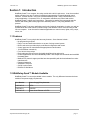
1.2 WebRelay-Quad™ Models Available
WebRelay-Quad™ is currently available in three models. The only difference between the three
models is the power supply requirements.
Part Number
Power Supply Requirements
X-WR-4R1-5
5VDC
X-WR-4R1-I
9-28VDC
X-WR-4R1-E
Power Over Ethernet or 5VDC
Xytronix Research & Design, Inc.
page 7
Revision 2.3
WebRelay-Quad™ Users Manual
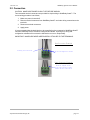
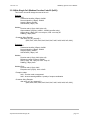
1.3 Connectors & Indicators
WebRelay-Quad™ has a removable terminal connector and an Ethernet connector. The terminal
connector is used to provide power to the internal web server, and is used to connect external
electrical loads to the relay contacts.
There are seven LED indicators on WebRelay-Quad™. The Power LED (green) indicates that the
unit is powered. Four LEDs (green) labeled Relay 1-4 which indicate that the corresponding relay
coil is energized. When the relay coils are energized, the NO (Normally Open) contacts are closed
and the NC (Normally Closed) contacts are open. The load device that is connected to the relay
contacts may be on or off when the coil is energized depending on how it is wired. The LINK
(green) LED indicates that WebRelay-Quad™ is properly connected to an Ethernet network. The
ACK LED (amber) flashes when there is network activity. Note that the LINK and ACT LEDs are
located on the Ethernet connector.
R e m o v a b le
T e r m in a l S t r ip
R e la y
S ta tu s
In d ic a to r
L ig h t s
Power
I n d ic a t o r
L ig h t
N e tw o rk
A c t iv it y
L ig h t
N e tw o rk
L in k
L ig h t
Xytronix Research & Design, Inc.
E th e rn e t
C o n n e c to r
page 8
Revision 2.3
WebRelay-Quad™ Users Manual
1.4 Example Configurations and Applications
WebRelay-Quad™ is very versatile and can be used in many applications. Several basic
installation schemes are illustrated in this section.
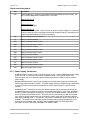
1.4.1 Basic Setup
The illustration below shows a simple WebRelay-Quad™ application. The example shows how a
3-color industrial light tower can be controlled remotely over an Ethernet network. The three lights
are connected to three of the relays so each light can be controlled individually. The lights can be
connected directly to the relay contacts because they are low power lights (LEDs). The controller
can be a web browser, a custom control application running on a computer, a PLC, or an
embedded industrial controller. Commands are sent to WebRelay-Quad™ over the Ethernet
network using standard IP protocols so the controller can be placed physically next to the light
tower or a distance away.
P o w e r S u p p ly fo r W e b R e la y Q uad
D e v ic e t o b e
C o n t r o lle d
( L ig h t T o w e r )
W e b R e la y - Q u a d
Vin+
Vin-
1C
2C
1NO
2NO
ht
Lig
1
Li
gh
t2
Light
3
3C
3N
O
COM
C o m p u t e r , P L C , I n d u s tr ia l
C o n t r o lle r , e tc .
IP
N e tw o rk
N o t e t h a t a s in g le p o w e r s u p p ly c o u ld b e
u s e d to p o w e r b o t h W e b R e la y - Q u a d a n d
L ig h t T o w e r .
P o w e r S u p p ly
fo r L ig h t T o w e r
+V
COM
Xytronix Research & Design, Inc.
page 9
Revision 2.3
WebRelay-Quad™ Users Manual
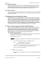
1.4.2 Controlling High Power Devices
WebRelay-Quad™ can be used to control high power devices by using an external relay. In this
configuration, WebRelay-Quad™ does not control the load directly, but controls the external relay
and the external relay controls the load. This is illustrated below.
D e v ic e to b e
C o n t r o lle d
N e u tra l
240V
AC Pow er
S o u rc e
P o w e r S u p p ly
( P o w e r s W e b R e la y )
(5 V D C o r 9 -2 8 V D C )
L in e
25 Am p
S o lid S t a t e R e la y
W e b R e la y - Q u a d
Vin+
Vin-
C o m p u te r , P L C , In d u s tr ia l C o n t r o lle r , e tc .
1C
1NO
Input
-
+
IP
N e tw o rk
1.4.3 Using WebRelay-Quad™ Without a Computer
WebRelay-Quad™ can be used in conjunction with other ControlByWeb products such as
WebRelay™ or the Five- Input Module. This allows users to control devices at a remote location
by using switches or buttons instead of using a computer. The illustration below shows how three
switches can remotely control three indicator lights in a light tower at a remote location. This
configuration offers many possibilities in security and remote control. The inputs can be driven by
switches, sensors, or digital outputs from a PLC or automation controller.
P o w e r S u p p ly fo r
F iv e I n p u t M o d u le
P o w e r S u p p ly fo r W e b R e la y Q uad
L ig h t T o w e r
S w itc h e s
F iv e In p u t M o d u le
2N O
L ig
3N O
1
IP
N e tw o rk
3C
2C , and
To 1C ,
L ig h t 3
ht
Li
In 3 +
CO M
In 2 +
t2
t 3
L ig h t 2
V in +
V in 1NO
gh
+5
In 1 +
W e b R e la y - Q u a d
V in +
V in G nd
In 1 In 2 In 3 -
L ig h
L ig h t 1
P o w e r S u p p ly
fo r L ig h t T o w e r
+V
CO M
Xytronix Research & Design, Inc.
page 10
Revision 2.3
WebRelay-Quad™ Users Manual
Section 2: Installation and Setup
Installation consists of mounting WebRelay-Quad™, connecting to an IP network, providing
power, configuring via a web browser, and wiring relay contacts to the device that will be
controlled.
2.1 Mounting
WebRelay-Quad™ can be be wall mounted or DIN rail mounted. It should be mounted in a clean
dry location where it is protected from the elements. Ventilation is recommended for installations
where ambient air temperature is expected to be high.
2.1.1 Wall Mounting
WebRelay-Quad™ includes two keyholes in the rear of its enclosure for wall mounting. Mount to
a wall by using two #8 screws. Attach the screws to the wall vertically spaced exactly 2.5 inches
apart. The head of the screws should be about 1/10 inch away from the wall. See Appendix C for
mechanical details.
2.1.2 DIN-Rail Mounting
WebRelay-Quad™ can be mounted to a standard (35mm by 7.55mm) DIN rail. Attach WebRelayQuad™ to the DIN rail by hooking the top hook on the back of the enclosure to the DIN rail and
then snap the bottom hook into place. Remove WebRelay-Quad™ from DIN rail using a flat-head
screwdriver. Insert the screwdriver into the notch in the release tab and pry against the enclosure
to release the bottom hook.
Xytronix Research & Design, Inc.
page 11
Revision 2.3
WebRelay-Quad™ Users Manual
2.2 Connection
CAUTION: MAKE SURE POWER IS SHUT OFF BEFORE WIRING!
Two removable terminal connectors are provided for simple wiring to WebRelay-Quad™. The
correct wiring procedure is as follows;
1. Make sure power is turned off.
2. Remove terminal connectors from WebRelay-Quad™ and make wiring connections to the
terminals.
3. Reconnect terminal connectors.
4. Apply power.
It is recommended that the load (device to be controlled) not be connected to WebRelay-Quad™
until after WebRelay-Quad™ has been configured and tested. By doing this, wiring and
configuration mistakes will not cause the load device to turn on unexpectedly.
IMPORTANT: MAKE SURE WIRES ARE PROPERLY ATTACHED TO THE TERMINALS!
B a d C o n n e c to r E x a m p le .
S t r a n d ( s ) o f w ir e a r e lo o s e
W ir e s a r e s t r ip p e d t o o f a r b a c k
G o o d C o n n e c t o r E x a m p le .
W ir e s a r e s t r ip p e d c o r r e c t
a m o u n t a n d th e r e a r e n o lo o s e
s tra n d s th a t c a n c a u s e s h o rts
Xytronix Research & Design, Inc.
page 12
Revision 2.3
WebRelay-Quad™ Users Manual
14-pin connector pinout:
Pin
VIN+
Description
Power supply input. Connect to the positive side of the appropriate power supply. DO
NOT EXCEED MAXIMUM POWER SUPPLY VOLTAGE.
Model X-WR-4R1-5
5VDC Power supply
Model X-WR-4R1-I
9~28VDC Power supply
Model X-WR-4R1-E
Power Over Ethernet model. These units do not require a power supply to be connected
to this pin when the unit is connected to an 802.3af compliant network. Alternatively, this
model can be powered using a 5VDC power supply.
VIN1C
Power supply ground (-) connection.
Relay 1 Common Contact
1NC
Relay 1 Normally Closed Contact
1NO
Relay 1 Normally Open Contact
2C
Relay 2 Common Contact
2NC
Relay 2 Normally Closed Contact
2NO
Relay 2 Normally Open Contact
3C
Relay 3 Common Contact
3NC
Relay 3 Normally Closed Contact
3NO
Relay 3 Normally Open Contact
4C
Relay 4 Common Contact
4NC
Relay 4 Normally Closed Contact
4NO
Relay 4 Normally Open Contact
2.2.1 Power Supply Connection
WebRelay-Quad™ requires power for its internal logic circuits. Connect appropriate power supply
to the Vin+ and Vin- terminals. Alternatively, WebRelay-Quad™ units with the Power Over
Ethernet option may be powered through the Ethernet connection instead of using an external
power supply.
Multiple WebRelay-Quad™ units may be connected to a single power supply by connecting the
power supply input terminals in parallel. The power supply must have a high enough current rating
to power all units connected (see specifications for current requirements for a specific model
number).
WebRelay-Quad™ units with the Power Over Ethernet option may be connected to an 802.3af
compliant Ethernet port instead of connecting an external power supply. In this case, WebRelayQuad™ is powered through the network port. In an 802.3af compliant network, a 48 Volt power
source is injected into the Ethernet line. This power source is provided by an 802.3af compliant
hub, switch, or power injector which may be located in a utility closet which could be a distance
away from WebRelay-Quad™. This option is very useful for installations where local power is not
available. The power injector may inject the 48 Volt power source through the data lines or the
spare lines in the Ethernet cable. DO NOT USE A POWER INJECTOR THAT APPLIES A
VOLTAGE TO BOTH THE DATA LINES AND THE SPARE LINES.
Xytronix Research & Design, Inc.
page 13
Revision 2.3
WebRelay-Quad™ Users Manual
2.2.2 Network Connection
Connect the Ethernet port to a 10 Base T or 10/100 Base T Ethernet connection. This typically
connects to an Ethernet hub, switch, or router. For configuration, WebRelay-Quad™ may be
connected directly to the Ethernet port on a computer using a “crossover” cable. Otherwise for
connection through a hub or router, a standard “straight-thru” cable should be used.
2.2.3 Relay Connection
The relay contacts internally connect directly to the 14-pin connector. No internal fuse is provided.
The relay contacts are rated at 1 Amp max (28V max). For larger loads, an external relay may be
used to control the load.
2.3 Establishing Communications for Setup
WebRelay-Quad™ is set up using a web browser. The first task is to establish communications
between a computer and the WebRelay-Quad™ device so that the browser-based configuration
can begin. To do this, the computer and WebRelay-Quad™ must be physically connected to the
same network and both must have IP addresses on the same network. There are two ways to set
up the computer and WebRelay-Quad™ so that they are on the same network. The first way
(Option 1), is to change the IP address of WebRelay-Quad™ to an address that is on the same
network as the computer. The second way (Option 2) is to change the IP address of the computer
to an address that is on the same network that WebRelay-Quad™ is set to by default.
2.3.1 Option 1: Assign a temporary IP address to WebRelay-Quad™
This option is used to TEMPORARILY assign an IP address to WebRelay-Quad™ without the
need to change the IP address of the configuration computer. Note that WebRelay-Quad™ will
only use this IP address as long as power is maintained. Once power is lost and restored,
WebRelay-Quad™ will use the IP address assigned in the setup page and not the temporary
address assigned here. This means that once communications are established, the desired IP
address should be entered into the network setup page using the browser.
To assign the temporary IP address...
1.
Make sure WebRelay-Quad™ and the configuration computer are connected to the same
physical network. This will not work through routers or gateways.
2.
Assign the address as follows...
Windows:
Open a Command Prompt (on Windows XP, select START, then RUN, then type “cmd”).
Type...
arp -s {new IP address} {serial number of WebRelay-Quad™ }
Note:
IP address format is: xxx.xxx.xxx.xxx
Serial number format is: ss-ss-ss-ss-ss-ss
For example, to set a WebRelay-Quad™ device (with serial number 00-0C-C801-00-01 ) to 10.10.10.40 the following command would be used.
arp -s 10.10.10.40 00-0c-c8-01-00-01
Next, type...
ping -l 102 {new IP address}
For example, if the new IP address is 10.10.10.40, the following command would
be used.
Xytronix Research & Design, Inc.
page 14
Revision 2.3
WebRelay-Quad™ Users Manual
ping -l 102 10.10.10.40
Linux/Unix:
Open a terminal, change to root user (su -, then enter root password).
Type...
arp -s {new IP address} {serial number of WebRelay-Quad™ }
Note:
IP address format is: xxx.xxx.xxx.xxx
Serial number format is: ss:ss:ss:ss:ss:ss
For example, to set a WebRelay-Quad™ device (with serial number 00-0C-C801-00-01 ) to 10.10.10.40 the following command would be used.
arp -s 10.10.10.40 00:0c:c8:01:00:01
Next, type...
ping -s 102 {new IP address}
For example, if the new IP address is 10.10.10.40, the following command would
be used.
ping -s 102 10.10.10.40
Mac OS X
Open a terminal,
Note that the terminal is in the “Utilities” directory which is in “Applications” directory.
type
sudo arp -s {new IP address} {serial number of WebRelay-Quad™ }
Note:
Administrator password is required.
IP address format is: xxx.xxx.xxx.xxx
Serial number format is: ss:ss:ss:ss:ss:ss
For example, to set a WebRelay-Quad™ device (with serial number 00-0C-C801-00-01 ) to 10.10.10.40 the following command would be used.
sudo arp -s 10.10.10.40 00:0c:c8:01:00:01
Next, type...
ping -s 102 {new IP address}
For example, if the new IP address is 10.10.10.40, the following command would
be used.
ping -s 102 10.10.10.40
Xytronix Research & Design, Inc.
page 15
Revision 2.3
WebRelay-Quad™ Users Manual
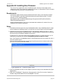
2.3.2 Option 2: Assign a temporary IP address to configuration computer
If the first option above is not used, you can use this option to communicate with WebRelayQuad™ . By default, WebRelay-Quad™ comes from the factory with an IP address of
192.168.1.2. Communications with WebRelay-Quad™ may be established by assigning an IP
address to the configuration computer that is on the same network as WebRelay-Quad™ (for
example the configuration computer could be assigned to 192.168.1.50) .
Instructions for changing the IP address of the computer that will be used for WebRelay-Quad™
configuration are given here. Note that these instructions are specifically for computers with the
Windows XP operating system. For setup using other operating systems, refer to the appropriate
users manual.
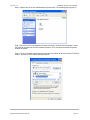
Step 1: Open the control panel by clicking on the start menu and then clicking on Control Panel.
(Note that control panel shown is in “Classic View”. If control panel is in “Category View” select the
“Classic View” option before proceeding.)
Xytronix Research & Design, Inc.
page 16
Revision 2.3
WebRelay-Quad™ Users Manual
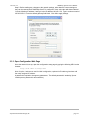
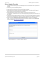
Step 2: Double click on the icon labeled Network Connections. The following menu will pop up.
Step 3: Right click on the icon labeled Local Area Connection. Another menu will appear. Select
the option at the bottom of the menu labeled Properties. The Local Area Connection Properties
window will appear.
Step 4: On the Local Area Connection Properties page scroll down to Internet Protocol (TCP/IPv4),
select it, and then click the button labeled properties.
Xytronix Research & Design, Inc.
page 17
Revision 2.3
WebRelay-Quad™ Users Manual
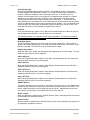
Step 5: Before making any changes to the network settings, write down the current settings so
they can be restored once WebRelay-Quad™ is configured. Next, select the radio button labeled
“Use the following IP address,” and type in the IP address 192.168.1.50. Type in a subnet mask of
255.255.255.0. Leave the default gateway field blank. Click OK to apply settings.
2.3.3 Open Configuration Web Page
Once the network is set up, open the configuration setup page by typing the following URL into the
browser:
http://192.168.1.2/setup.html
Note: If option 1 above was used for initial configuration, replace the IP address given here with
the newly assigned IP address.
A password is required to change any parameters. The default password is ‘webrelay’ (do not
include quotes, password is case sensitive).
Xytronix Research & Design, Inc.
page 18
Revision 2.3
WebRelay-Quad™ Users Manual
2.4 Web-Based Setup
WebRelay-Quad™ is fully configurable through HTML 4.0 compliant web browsers such as
Internet Explorer and Mozilla Firefox. It’s easy to use tab based menu system has been designed
to allow the unit to be configured easily. Note that in this chapter, the default IP address of
192.168.1.2 is used in all examples. If the IP address has been changed, substitute the new IP
address for the address shown in the examples.
Before proceeding, make sure a network connection has been established between the computer
and WebRelay-Quad™. This is done by typing the following URL into the web browser:
http://192.168.1.2/setup.html. Another way to check communications is to ping WebRelayQuad™ (from the command prompt (type ping 192.168.1.2)). Each setup page is described
below.
2.4.1 Main Setup Page
This is the initial page that appears when the URL http://192.168.1.2/setup.html is entered into the
web browser. It provides basic information about the WebRelay-Quad™ unit.
Xytronix Research & Design, Inc.
page 19
Revision 2.3
WebRelay-Quad™ Users Manual
Navigating between setup pages is done by clicking on the tabs at the top of the page. All setup
pages require a password. The default password is ‘webrelay’ (no quotes, all lower case) and no
user name is required.
Each setup page has a “Submit” button and a “Reset” button at the bottom of the page. After
entering the desired parameters into each page, the “Submit” button must be pressed before any
parameters will be saved. If a mistake is made in entering the parameters, the “Reset” button may
be used to restore all parameters on the page to their current settings. The “Reset” button is only
effective before the “Submit” button is pressed.
Xytronix Research & Design, Inc.
page 20
Revision 2.3
WebRelay-Quad™ Users Manual
2.4.2 Network Setup Page
The network parameters are changed on this page. Note that if multiple WebRelay-Quad™ units
are used on the same network, install one unit at a time and set the IP address of each unit before
connecting the next unit to the network. This avoids having multiple WebRelay-Quad™ units
installed on the network with the same factory default IP address at the same time. It may be
necessary to clear the arp cache each time you swap WebRelay-Quad™ units on the network (this
is because each unit has the same default IP address but different mac address). This is done by
typing arp -d in the command prompt of a Windows computer (arp -d -a as super user on Apple
OSX). Also note that the unit must be power-cycled (power disconnected, then reconnected)
before network settings take effect. No other setup page requires power-cycling for the settings
take effect.
IP Address
WebRelay-Quad™ requires a static IP address. This is a unique address that identifies
WebRelay-Quad™ on the network. Dynamic IP address assignment is not supported. The
lack of dynamic IP addressing support is intentional because a dynamically changing the IP
address would make it difficult for a client to access the web server built into WebRelayQuad™. The IP address is specific to the network where WebRelay-Quad™ will be installed,
and must be obtained from the network administrator.
This guide is not meant to be a tutorial on IP addressing, however a few comments about IP
addressing are given here.
Xytronix Research & Design, Inc.
page 21
Revision 2.3
WebRelay-Quad™ Users Manual
If WebRelay-Quad™ will be used over the Internet, the IP address must be a routable address
assigned by the upstream Internet Service Provider (ISP).
In cases where the ISP only provides a single routable IP address for the entire network (this
is typical with ISPs such as cable providers), a proxy server (or gateway router) may be used.
A proxy server allows multiple devices to connect to the Internet using a single routable IP
address. Many small routers from LinkSys, Dlink, and Netgear perform proxy server functions.
If a proxy server is used, WebRelay-Quad™ will not be accessible from the Internet until the
proxy server is properly configured (forward proper port to WebRelay-Quad™). This
information is mentioned for convenience but details of setting up a configuration such as this
is beyond the scope of this manual.
If WebRelay-Quad™ is used on a private network only and is NOT used over the Internet, a
routable IP address is not necessary. This may be the case when WebRelay-Quad™ is used
to control (or monitor) a device in another room or a nearby building.
If WebRelay-Quad™ will be installed on a simple, private network that does not connect to the
Internet, the default IP address may be used as long as no other device on the network uses
the same address. If multiple WebRelay-Quad™ units are installed on the same network,
each unit must have its own unique IP address. For example, WebRelay-Quad™ comes from
the factory with a default IP address of 192.168.1.2. If multiple units are used, change the IP
address for each unit (192.168.1.3, 192.168.1.4, 192.168.1.5 etc.).
Netmask:
This specifies the size of the local network. This must be obtained from the network
administrator. By default, the netmask is set to 255.255.255.0.
Broadcast:
This specifies the broadcast address. This must be obtained from the network administrator.
By default, this is set to 192.168.1.255.
Gateway:
This specifies the IP address of the gateway router. This must be obtained from the network
administrator. By default, this is set to 192.168.1.1.
TCP Port:
This specifies the TCP port used for communications with WebRelay-Quad™. By default, the
port is set to 80 which is the standard http port. It is recommended that the port not be
changed without an understanding of TCP/IP and ports.
Changing the port can be useful for accessing multiple WebRelay-Quad™ devices which are
installed behind a gateway router on a private network that uses non-routable IP addresses
(192.168.x.x, 10.x.x.x, and 172.16.x.x through 172.31.x.x are non-routable or private IP
addresses). In this case, each WebRelay-Quad™ unit would be assigned a different port (for
example 8000, 8001, 8002, etc). The gateway router would be set up to forward all traffic for
each of the assigned ports to the IP address of the WebRelay-Quad™ unit which uses that
port. The WebRelay-Quad™ units could then be accessed from outside the private network
by entering the IP address of the gateway and the port for the desired WebRelay-Quad™ unit.
Note that whenever any port is assigned other than port 80, all communications with that
WebRelay-Quad™ device must include the port. For example, if WebRelay-Quad™ is
assigned port 8000, access to the setup page would require the following URL to be entered;
http://192.168.1.2:8000/setup.html.
Xytronix Research & Design, Inc.
page 22
Revision 2.3
WebRelay-Quad™ Users Manual
An example screenshot of a gateway router configuration is given below. This setup allows
seven ControlByWeb™ products to be accessed on a private network behind a gateway
router. Note that this screenshot is simply an example of a typical router setup page. Routers
will vary. In the example, the seven ControlByWeb™ products are assigned IP addresses of
10.10.10.41 to 10.10.10.47. The first device labeled WebRelay-Quad 1 has an IP address of
10.10.10.41 and is assigned port 8001. Note that in the WebRelay-Quad™setup page (under
Network settings tab), TCP Port 8001 must be specified for this device. The second device,
labeled WebRelay-Quad 2 has an IP address of 10.10.10.42 and is assigned port 8002. This
WebRelay-Quad™ must have its TCP Port set to 8002 in it's network settings page. This
pattern continues through 10.10.10.77 which is assigned the port 8007. To access the
ControlByWeb™ units from the Internet, enter the IP address of the gateway plus the port
number of the desired device.
Modbus Port:
This specifies the port used for Modbus/TCP communications with WebRelay-Quad™. By
default this is set to port 502 which is the standard Modbus port. For users not familiar with
Modbus, Modbus is a messaging structure protocol used in industrial manufacturing control
and automation. It is an open protocol and offers interoperability with software and devices
from other manufacturers. If Modbus is not used, this setting can be ignored. Modbus
communications are disabled whenever the control password is enabled.
Speed
This option sets the data rate of the Ethernet port. Both 10Mbps and 100Mbps can be
selected. The 100Mbps option offers faster communications but the amount of data to and
from WebRelay-Quad™ is so small that users will not likely notice much of a difference. When
WebRelay-Quad™ is set to 10Mbps, it draws less power and runs a little cooler which
translate into a longer product life. IT IS RECOMMENDED THAT THIS SETTING BE LEFT AT
10MBPS UNLESS THE USER HAS A SPECIFIC REASON TO USE 100MBPS.
Mode
This option allows the Ethernet port to be set to Half Duplex or Full Duplex. Legacy Ethernet
operates in Half Duplex mode which means that devices can either send data or receive data,
but not both at the same time. Full duplex means that devices can send and receive data at
the same time.
Xytronix Research & Design, Inc.
page 23
Revision 2.3
WebRelay-Quad™ Users Manual
2.4.3 Password Setup Page
The password setup page is used to change and enable passwords. A password is required for
the setup pages but is optional for the control page. The password is enabled or disabled for the
control page by using the Yes or No radio buttons. Enabling the control page password also
enables the requirement for a password when reading/writing XML pages. Enabling the control
page password also disables the ability to communicate with WebRelay-Quad™ using Modbus.
Note that when the password is changed, the password may be displayed in the browser’s history
in clear text. It is advisable to clear the browsers history after setting the password. Passwords
may be up to 10 characters.
Xytronix Research & Design, Inc.
page 24
Revision 2.3
WebRelay-Quad™ Users Manual
2.4.4 Relay Setup Pages
These pages are used to set up the function of each of the four relays, and how each relay is
represented on the control page. All four pages are identical, with the exception of the Relay 1
page which also includes a field for the main header text on the control page, the option to
automatically refresh the control page, and the time duration for auto refresh.
The following settings are only included on the Relay 1 setup page and not on Relay 2,3 or 4
setup pages.
Main Header Text:
This text will be displayed in the main header area of the control page. This field can be up to
25 characters in length.
Xytronix Research & Design, Inc.
page 25
Revision 2.3
WebRelay-Quad™ Users Manual
Auto Refresh Page:
Web pages traditionally display static information. The WebRelay-Quad™ control page,
however, displays information that is dynamic. Each time the control page is loaded to the
browser, it displays a snapshot of the current status of the unit. If the state of the unit
changes, the information on the control page will be outdated unless the page is re-loaded.
Whenever a user changes the state of the relay via the web browser, the web page will
automatically reload the control page to display current information. If, however, the relay
state changes due to a change due to a command sent from another machine, the relay state
will not be updated and the control page information will be obsolete. The ‘Auto Refresh Page’
option will cause the control page to continually update its contents by setting a timer in the
web page that causes it to be reloaded at a specified time interval.
Duration:
If the ‘Auto Refresh Page’ option is set to Yes, this field specifies the time interval in seconds
that the page will be refreshed. It can be set from 1 to 32 seconds.
The following settings are included on all four relay setup pages. The settings correspond
only to the relay associated with that page.
Relay Description:
This text is used to describe the function of the relay on the control page. This text will not
appear if the ‘Display Relay Status’ is set to No, the ‘On/Off Buttons’ is set to 0, and the ‘Pulse
Button’ is set to No. This field can be up to 20 characters in length.
Display Relay Status:
When this option is set to Yes, the relay status will be displayed on the control page. If it is set
to No, the relay status will not be displayed.
Status ON Color:
When the ‘Display Relay Status’ option is set to Yes, this field specifies the color that will be
displayed when the relay is on (coil energized).
Status ON Text:
When the ‘Display Relay Status’ option is set to Yes, this field specifies the text that will be
displayed when the relay is on (coil energized).
Status OFF Color:
When the ‘Display Relay Status’ option is set to Yes, this field specifies the color that will be
displayed when the relay is off (coil not energized).
Status OFF Text:
When the ‘Display Relay Status’ option is set to Yes, this field specifies the text that will be
displayed when the relay is off (coil not energized).
ON/OFF Buttons:
This option allows the user to specify 0, 1, or 2 buttons to turn the relay on or off. Zero buttons
disables the users ability to turn the relay on and off (a pulse button may still be included... see
below). One button may be used to toggle the relay on and off. Two buttons gives the user
one button to turn the relay on and another button to turn the relay off.
Button 1 Label:
When 1 or 2 buttons is selected in the ‘ON/OFF Buttons’ option, this field specifies the text that
will be displayed in pushbutton number 1.
Button 2 Label:
When 2 buttons is selected in the ‘ON/OFF Buttons’ option, this field specifies the text that will
be displayed in pushbutton number 2.
Xytronix Research & Design, Inc.
page 26
Revision 2.3
WebRelay-Quad™ Users Manual
Pulse Button:
This option allows the user to include a pulse button to control the relay. If the pulse button is
included, the relay will pulse for the time specified in the ‘Pulse Duration’ field in the
‘Relay/Input’ page each time the button is pressed.
Pulse Button Label:
When the ‘Pulse Button’ option is set to Yes, the text entered here will appear in the pulse
button on the control page.
Pulse Duration:
When WebRelay-Quad™ receives a command (from over the network or through an input
change) to pulse the relay, this is the time in seconds that the relay will pulse on. This time
can be set from 0.1 seconds to 86,400 seconds (1 day). Note that each time WebRelayQuad™ receives a pulse command, the relay will be turned on (if not on already) and the
pulse timer will be reset. If WebRelay-Quad™ receives a pulse command and and a second
pulse command comes in before the pulse timer has expired, the relay will remain on and the
pulse timer will be reset so the duration of the pulse will be extended. If pulse commands are
issued continuously so that the pulse timer is not allowed to expire, the relay will remain on
until after the last pulse command was sent (to be precise, the relay will go off at the time of
the last command plus the Pulse Duration time). The pulse command can be canceled before
the pulse duration time has expired by issuing any other command. The factory default setting
for this is 1.5 seconds.
Xytronix Research & Design, Inc.
page 27
Revision 2.3
WebRelay-Quad™ Users Manual
Section 3: Operation
WebRelay-Quad™ can be operated by using a web browser, by sending text commands to an
XML status/control page, or by sending Modbus/TCP requests.
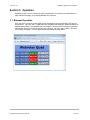
3.1 Browser Operation
Once the unit is set up, the control page may be accessed by typing the following URL into the
web browser: http://192.168.1.2 (Note that if the IP address was changed, replace the default IP
address shown with the new address that was assigned. Note also that if any port is used other
than port 80, the port must also be included in the request: http://192.168.1.2:8000 ) The new
control page will appear. A control page with default settings is shown below.
Xytronix Research & Design, Inc.
page 28
Revision 2.3
WebRelay-Quad™ Users Manual
3.2 XML Operation
Custom computer applications may be created to monitor and control WebRelay-Quad™ without
using a web browser. Monitoring the state of the relays is done by sending a GET request to port
80 (or port specified in setup) for the XML page. Control of the relay is done by sending GET
requests to the same page. This can be demonstrated by entering commands into the URL line of
a web browser.
3.2.1 state.xml
Request the current state: http://192.168.1.2/state.xml
This will return the following XML page.:
<?xml version="1.0" encoding="utf-8" ?>
<datavalues>
<relay1state>0</relay1state>
<relay2state>1</relay2state>
<relay3state>1</relay3state>
<relay4state>1</relay4state>
</datavalues>
The tags <relay1state>... <relay4state> indicate the current state of each of the four relays.
Values for the tags are described below.
XML Tags*
Values
<relayXstate>
0 = Off (coil off)
1 = On (coil energized)
* 'X' is replaced by the relay number.
3.2.2 XML Control
Commands can be sent to WebRelay-Quad™ to control the relays. Commands are sent using
variables called relay1State, relay2State, relay3State and relay4State. Examples of using
relayXState (X represents the appropriate relay) are given here.
Note: http://192.168.1.2/ would be included on all of the following commands.
Command
Description
State.xml?relay1State=0
Turn Relay 1 Off
State.xml?relay1State=1
Turn Relay 1 On
State.xml?relay1State=1&relay3State=0
Turn Relay 1 ON, Turn Relay 3 OFF
Commands can be issued to pulse the relays instead of simply turning them on or off by setting
the relayXState to 2. Commands can also specify pulse times so that the relay can be pulsed for
times other than the times specified in the relay setup pages. This is done by sending an
additional variable called pulseTimeX (once again, X represents the appropriate relay).
Command
Description
state.xml?relay1State=2
Pulse Relay 1 for the preset time
state.xml?relay1State=2&pulseTime1=5
Pulse Relay 1 for 5 seconds
state.xml?relay3State=2&pulseTime3=10
Pulse Relay 3 for 10 seconds
Xytronix Research & Design, Inc.
page 29
Revision 2.3
WebRelay-Quad™ Users Manual
The pulseTimeX variable does not change the pulse time specified in the setup page and it is not
stored or recorded. The pulseTimeX variable only changes the pulse duration for the single pulse
initiated by that command. In other words, you must issue the pulseTimeX for each pulse
command that differs from the preset pulse time. For example, suppose the pulse time is set to
1.5 seconds in the configuration pages. To issue one 1.5 second pulse, three five second pulses,
and a 1.5 second pulse once again, you would issue the following commands...
state.xml?relay1State=2
state.xml?relay1State=2&pulseTime1=5
state.xml?relay1State=2&pulseTime1=5
state.xml?relay1State=2&pulseTime1=5
state.xml?relay1State=2
This will pulse the relay for the preset time (1.5 seconds)
This will pulse the relay for 5 seconds.
This will pulse the relay for 5 seconds
This will pulse the relay for 5 seconds
This will pulse the relay for the preset time (1.5 seconds)
Note: http://192.168.1.2/ would be included on all commands above
Multiple relays can be changed with a single command by submitting multiple relayXState
variables separated by an ampersand symbol (&). All four relayXState variables or a subset of the
relayXState variables can be included. The relayXState variables can be in any order. Relays that
are already in the desired state will not be affected by on/off commands.
Note: Pulse commands will reset the pulse timer each time a command is received.
The following line illustrates how to turn ‘ON’ Relay 1, turn ‘ON’ Relay 2, and turn ‘OFF’ Relay 4.
http://192.168.1.2/state.xml?relay1State=1&relay4State=0&relay2State=1
When the above commands are sent to WebRelay-Quad™, its current state is returned in the form
of an XML page.
Note: The XML reply does not contain headers. To generate an XML reply with headers use the
following command:
Command
Description
stateFull.xml
Return the XML reply with headers
The commands can also be sent without having WebRelay-Quad™ return the XML page. This is
accomplished by adding the noReply field as follows.
Command
Description
state.xml?relay1State=1&noReply=1 Turn Relay 1 ON without returning state.
state.xml?relay1State=0&noReply=1 Turn Relay 1 OFF without returning state.
Xytronix Research & Design, Inc.
page 30
Revision 2.3
WebRelay-Quad™ Users Manual
3.2.3 GET Requests
GET requests can be used by custom applications to monitor and control the relays. A few
example GET requests are provided below.
No Password Enabled:
GET requests to the device for specific files.
Example: Request home.html
GET /home.html HTTP/1.1\r\n\r\n
Example: Turn Relay 1 ON
GET /state.xml?relay1State=1 HTTP/1.1\r\n\r\n
Password Enabled:
If the control password is enabled in the WebRelay-Quad™ unit and the XML page is requested
through a browser, the browser will prompt the user for the password. If the XML request is sent
from another application and not a browser, the html request will need to contain the password
encoded using the base 64 encoding scheme. The html request header without the password
looks like this:
GET /state.xml?noReply=1 HTTP/1.1 (Terminated with two \r\n)
The html request header with the password looks like this:
GET /state.xml?relay2State=1&noReply=1 HTTP/1.1 (Terminated with one \r\n)
Authorization: Basic bm9uZTp3ZWJyZWxheQ== (Terminated with two \r\n\)
where bm9uZTp3ZWJyZWxheQ== is the base 64 encoded version of the username and password
none:webrelay.
A utility is provided at http://www.ControlByWeb.com/encoder that can be used to encode the
password. The utility is used by simply typing the string username:password into the website and
pressing encode.
Xytronix Research & Design, Inc.
page 31
Revision 2.3
WebRelay-Quad™ Users Manual
3.3 Modbus Operation
WebRelay-Quad™ can be controlled (and read) using Modbus/TCP protocol. This provides a
standard means of using WebRelay-Quad™ in conjunction with devices and software from other
manufacturers. This section contains the information necessary to communicate with WebRelayQuad™ using Modbus/TCP. This is not a tutorial on Modbus and it is assumed that reader is
already familiar with Modbus. Detailed Modbus information can be found at
http://www.modbus.org.
It is important to note that when the control password in WebRelay-Quad™ is enabled,
Modbus/TCP communications are disabled. This is because Modbus/TCP does not provide a
mechanism for password protection. Make sure the control password is disabled (default) before
using Modbus with WebRelay-Quad™.
WebRelay-Quad™ functions as a Modbus server. Client devices open a connection with
WebRelay-Quad™ on port 502 (unless another modbus port is selected) and sends commands or
requests to to read the state of a relay, or change a relay. When WebRelay-Quad™ receives a
command, it will perform the desired function and return a response. The following commands are
available:
━
━
━
━
Read Coils (Modbus function 01) - read the status of the relay (and/or the input).
Write Single Coil (Modbus function 05) - change the relay state
Write Multiple Coils (Modbus Function Code 15) – change multiple relays at the same time
Write Multiple Registers (Modbus function 16) - pulse the relay or multiple relays.
Multiple commands may be sent without closing and re-opening the connection but if no data is
transferred for about 50 seconds the connection will time out. To keep the connection open, a
read request can be sent periodically.
3.3.1 Read Coils (Modbus Function Code 01 (0x01))
This function returns the state of the relay coil(s).
Relay 1 is at address 0x0000, relay 2 is at address 0x0001, relay 3 is at address 0x0002, and
relay 4 is at address 0x0003. Multiple relays may be read at the same time by specifying the
correct starting address and quantity of coils. When address 0x0000 is used, the quantities of
coils can be 0x0001, 0x0002, x0003 or 0x0004. When address 0x0003 is used, the only valid
quantity of coils is 0x0001. This means that relays 1 and 4 cannot be read without reading relays
2 & 3.
Request
Modbus/TCP:
Transaction identifier (2 Bytes): 0x0001
Protocol identifier (2 Bytes): 0x0000
Length (2 Bytes): 0x0006
Unit identifier (1 Byte): 0xff
Modbus:
Function code (1 Byte): 0x01 (read coils)
Starting address (2 Bytes): 0x0000 (0x0000 ~ 0x0003)
Quantity of coils (2 Bytes): 0x0002 (0x0001 ~ 0x0004)
Character String Example:
char read_coils_mb_request[] =
{0x00, 0x01, 0x00, 0x00, 0x00, 0x06, 0xff, 0x01, 0x00, 0x00, 0x00, 0x02 };
Response
Modbus/TCP:
Transaction identifier (2 Bytes): 0x0001
Xytronix Research & Design, Inc.
page 32
Revision 2.3
WebRelay-Quad™ Users Manual
Protocol identifier (2 Bytes): 0x0000
Length (2 Bytes): 0x0004
Unit identifier (1 Byte): 0xff
Modbus:
Function code (1 Byte): 0x01 (Read coils)
Byte count (1 Byte): 0x01
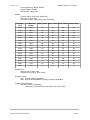
Coil status (1 Byte): 0x00 to 0x0F (see chart below)
Data Byte
(hex)
LS Data Bits
(binary)
Relay 4 State Relay 3 State Relay 2 State
Relay1 State
0x00
0000
off
off
off
off
0x01
0001
off
off
off
on
0x02
0010
off
off
on
off
0x03
0011
off
off
on
on
0x04
0100
off
on
off
off
0x05
0101
off
on
off
on
0x06
0110
off
on
on
off
0x07
0111
off
on
on
on
0x08
1000
on
off
off
off
0x009
1001
on
off
off
on
0x0A
1010
on
off
on
off
0x0B
1011
on
off
on
on
0x0C
1100
on
on
off
off
0x0D
1101
on
on
off
on
0x0E
1110
on
on
on
off
0x0F
1111
on
on
on
on
Modbus Error:
Function code (1 Byte): 0x81
Exception code (1 Byte): 0x01 or 0x02
Exception codes:
0x01 - Function code not supported
0x02 - Incorrect starting address / quantity of outputs combination
Character String Example:
char read_coils_mb_response[] =
{0x00, 0x01, 0x00, 0x00, 0x00, 0x04, 0xff, 0x01, 0x01, 0x01};
Xytronix Research & Design, Inc.
page 33
Revision 2.3
WebRelay-Quad™ Users Manual
3.3.2 Write Single Coil (Modbus Function Code 05 (0x05))
This function is used to change the state of the coil
Request
Modbus/TCP:
Transaction identifier (2 Bytes): 0x0001
Protocol identifier (2 Bytes): 0x0000
Length (2 Bytes): 0x0006
Unit identifier (1 Byte): 0xff
Modbus:
Function code (1 Byte): 0x05 (write coil)
Output address (2 Bytes): 0x0000 – 0x0003 (specifies relay)
Output value (1 Byte): 0xff - turn relay on, 0x00 - turn relay off
Padding (1 Byte): 0x00
Character String Example:
char write_coil_mb_request[] =
{0x00, 0x01, 0x00, 0x00, 0x00, 0x06, 0xff, 0x05, 0x00, 0x00, 0xff, 0x00 };
Response
Modbus/TCP:
Transaction identifier (2 Bytes): 0x0001
Protocol identifier (2 Bytes): 0x0000
Length(2 Bytes): 0x0006
Unit identifier (1 Byte): 0xff
Modbus:
Function code (1 Byte): 0x05 (write coil)
Reference number (2 Bytes): 0x0000
Data (1 Byte): 0xff - relay on, 0x00 - relay off
Padding (1 Byte): 0x00
Modbus Error:
Function code (1 Byte): 0x85
Exception code (1 Byte): 0x01 or 0x02
Exception codes:
0x01 - Function code not supported
0x02 - Incorrect starting address / quantity of outputs combination
Character String Example:
char write_coil_mb_response[] =
{0x00, 0x05, 0x00, 0x00, 0x00, 0x06, 0xff, 0x05, 0x00, 0x00, 0xff, 0x00 };
Xytronix Research & Design, Inc.
page 34
Revision 2.3
WebRelay-Quad™ Users Manual
3.3.3 Write Multiple Coils (Modbus Function Code 15 (0x0F))
A single byte can be written to set the state of all four relays. To do this, set the starting address to
0, set the quantity of outputs to 4, and write a single byte with the appropriate value according to
the table below.
Data Byte
(hex)
LS Data Bits
(binary)
Relay 4 State Relay 3 State Relay 2 State Relay1 State
0x00
0000
off
off
off
off
0x01
0001
off
off
off
on
0x02
0010
off
off
on
off
0x03
0011
off
off
on
on
0x04
0100
off
on
off
off
0x05
0101
off
on
off
on
0x06
0110
off
on
on
off
0x07
0111
off
on
on
on
0x08
1000
on
off
off
off
0x009
1001
on
off
off
on
0x0A
1010
on
off
on
off
0x0B
1011
on
off
on
on
0x0C
1100
on
on
off
off
0x0D
1101
on
on
off
on
0x0E
1110
on
on
on
off
0x0F
1111
on
on
on
on
Alternatively, to modify the state of one, two, or three relays only, the starting address and quantity
of outputs can be set to values other than 0, and 4 respectively.
Request
Modbus/TCP:
Transaction identifier (2 Bytes): 0x0001
Protocol identifier (2 Bytes): 0x0000
Length (2 Bytes): 0x0008
Unit identifier (1 Byte): 0xff
Modbus:
Function code (1 Byte): 0x0f (write coil)
Starting address (2 Bytes): 0x0000 ~ 0x0003
Quantity of outputs (2 Bytes): 0x0001 ~ 0x0004
Byte count (1 Byte): 0x01
Output value (1 Byte): 0x00 ~ 0x0f (see table above)
Character String Example:
char write_mult_coil_mb_request[] =
{0x00, 0x01, 0x00, 0x00, 0x00, 0x08, 0xff, 0x0f, 0x00, 0x00, 0x00, 0x01, 0x01,
0x0F };
Xytronix Research & Design, Inc.
page 35
Revision 2.3
Response
Modbus/TCP:
Transaction identifier (2 Bytes): 0x0001
Protocol identifier (2 Bytes): 0x0000
Length(2 Bytes): 0x0006
Unit identifier (1 Byte): 0xff
WebRelay-Quad™ Users Manual
Modbus:
Function code (1 Byte): 0x05 (write coil)
Starting address (2 Bytes): 0x0000
Quantity of outputs (1 Byte): 0xff - relay on, 0x00 - relay off
Modbus Error:
Function code (1 Byte): 0x8f
Exception code (1 Byte): 0x01 or 0x02
Exception codes:
0x01 - Function code not supported
0x02 - Incorrect starting address / quantity of outputs combination
Character String Example:
char write_coil_mb_response[] =
{ 0x00, 0x05, 0x00, 0x00, 0x00, 0x06, 0xff, 0x05, 0x00, 0x00, 0xff, 0x00};
3.3.4 Write Multiple Registers (Modbus Function Code 16 (0x10))
This is used to pulse the relay(s) for a specified time. When WebRelay-Quad™ receives this
command, it immediately turns the appropriate relay coil(s) on (if not on already on) and starts the
pulse timer. The relay(s) are selected by writing the pulse time to the register(s) associated with
the appropriate relay(s). The pulse time is specified in the register value field and can range from
0.1 seconds to 86400 seconds (1 day). When the pulse time expires, the relay coil will be turned
off. If a pulse time command is sent with a value greater than 86400, the pulse timer will be set to
86400. If a pulse time command is sent with a value less than 0.1, the pulse timer will be set to
0.1. If any commands are sent to WebRelay-Quad™ (commands may be modbus, xml or html)
before the pulse timer has expired, the pulse timer will be canceled immediately and the new
command will be executed.
The pulse time is provided in IEEE 754 floating point format. The four data bytes are treated as
two individual big endian 16-bit words but the least significant word is sent first. In other words,
the 32-byte floating point number represented as ABCD is sent as CDAB. In the example shown
below, the relay will pulse for 10 seconds. Ten seconds is represented using a floating point
number of 41200000. It is transferred as 00004120.
Request
Modbus/TCP:
Transaction identifier (2 bytes): 0x0001
Protocol identifier (2 bytes): 0x0000
Length (2 bytes): 0x000b
Unit identifier (1 byte): 0xff
Modbus:
Function code (1 Byte): 0x10 (Write Multiple Registers)
Starting address (2 Bytes): 0x0010 (0x0010 relay1, 0x0012 relay 2, 0x0014 relay 3,
0x0016 relay 4)
Number of registers (2 Bytes): 0x0002 (2 registers for each relay to be pulsed)
Byte count (1 Byte): 0x04 (2 times the number of registers)
Register value (4 Bytes for each relay to be pulsed): 00 00 41 20 (10 second pulse time)
Xytronix Research & Design, Inc.
page 36
Revision 2.3
WebRelay-Quad™ Users Manual
Character String Example:
char write_registers_mb_request =
{0x00, 0x01, 0x00, 0x00, 0x00, 0x0b, 0xff, 0x10, 0x00, 0x10, 0x00, 0x02, 0x04,
0x00, 0x00, 0x41, 0x20 };
Response
Modbus/TCP:
Transaction identifier (2 Bytes): 0x0001
Protocol identifier (2 Bytes): 0x0000
Length (2 Bytes): 0x0006
Unit identifier: 0xff
Modbus:
Function (1 Byte): 0x10 (Write Multiple Registers)
Reference number (2 Bytes): 0x0010
Word count (2 Bytes): 0x0002
Modbus Error:
Function code (1 Byte): 0x90
Exception code (1 Byte): 0x01, 0x02, 0x03, or 0x04
Exception codes:
0x01 - Function code not supported
0x02 - Incorrect starting address / quantity of outputs combination
Character String Example:
char write_registers_mb_response[] =
{0x00, 0x05, 0x00, 0x00, 0x00, 0x06, 0xff, 0x10, 0x00, 0x10, 0x00, 0x02 };
Xytronix Research & Design, Inc.
page 37
Revision 2.3
WebRelay-Quad™ Users Manual
Appendix A: Restoring Factory Default Settings
In the event that the IP address or passwords are forgotten, WebRelay-Quad™ may be restored to
its original factory default settings. To do this, first remove the power from the unit. Next, insert a
thin object (such as a toothpick) through the small hole in the bottom of the unit to press the small
button that is located inside the unit. When the object is inserted, a tactile feel can be detected as
the button is depressed. While holding the button down, apply power and wait for about 10
seconds. After about 10 seconds, release the button. Now all settings will be back to the original
factory defaults.
CAUTION: DO NOT USE METAL OBJECTS FOR THIS FUNCTION.
S m a ll h o le
to a c c e s s
R e s e t B u tto n
Xytronix Research & Design, Inc.
page 38
Revision 2.3
WebRelay-Quad™ Users Manual
Appendix B: Installing New Firmware
From time to time, updates are made to WebRelay-Quad™ firmware. The firmware can be
updated in the field. The procedure for updating the firmware is outlined below. Please note that it
is important that this procedure is followed precisely.
Requirements
The firmware update software requires Windows XP/Vista/7 with the .Net framework installed.
The .Net framework is generally installed automatically through Windows update. To install it
manually, go to the following address:
http://www.microsoft.com/downloads/details.aspx?FamilyId=333325FD-AE52-4E35-B531508D977D32A6&displaylang=en
Select the Download button. Once you've downloaded the installation file, double click on the
installation file to install the framework.
Setup
1. Download the firmware zip file from the ControlByWeb website. Only a WebRelay-Quad™ image
can be installed on a WebRelay-Quad™ so make sure the correct image is being downloaded.
2. bootloader.exe will connect to WebRelay-Quad™ using default IP address 192.168.1.2, not the
address currently assigned to WebRelay-Quad™. After the update, all settings will be lost and the
device will return to its default IP address of 192.168.1.2.
Configure the PC to the same subnet as the IP address 192.168.1.2, such as 192.168.1.10. For
instructions on doing this, see section 2.3 Establishing Communications for Setup.
Note: The IP address of the WebRelay-Quad™ will automatically be set to the default 192.168.1.2
during the update process.
Note: A crossover cable cannot be used during the update procedure; an ethernet switch will be
necessary to properly update the firmware.
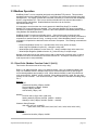
Figure Appendix B.1 - Firmware Update Utility
3. Open the bootloader.exe utility on the computer by double clicking on the downloaded file (Figure
Appendix B.1).
4. Within the ControlByWeb™ Programmer utility programmer, select File, then Open. Specify the
firmware image downloaded from the ControlByWeb™ web site.
Xytronix Research & Design, Inc.
page 39
Revision 2.3
WebRelay-Quad™ Users Manual
Device Upgrade Procedure
Carefully follow the following steps to put WebRelay-Quad™ into bootloader mode and perform the
upgrade:
1. Remove DC power from WebRelay-Quad™.
2. Using a small, non-conductive tool, press and hold the reset button.
3. While holding the reset button, apply power to WebRelay-Quad™. The LINK and ACT lights will
flash. Continue to hold the reset button for the next step.
4. While holding the reset button, press the Upload Firmware button at the bottom of the
ControlByWeb™ Programmer window. After the programming process begins, the reset button can
be released
5. Programming will take approximately 20-30 seconds. The LINK LED will stop flashing and remain lit
during this time. WebRelay-Quad™ will be set to factory defaults with an IP address of 192.168.1.2.
6. Refer to section 2.3 Establishing Communication for Setup to reconfigure the WebRelayQuad™. Verify the new version of firmware has been installed by viewing the default Setup Page
with a web browser (http://192.168.1.2/setup.html).
Figure Appendix B.2 - Firmware Update Complete
Xytronix Research & Design, Inc.
page 40
Revision 2.3
WebRelay-Quad™ Users Manual
Appendix C: Specifications
Power Requirements:
Model X-WR-4R1-5
Voltage: 5VDC ± 5%
Current: See table below for typical values
Power Supply
All Relays OFF
5 VDC
All Relays ON
10 Mbps
100 Mbps
10 Mbps
100 Mbps
173 mA
302 mA
337 mA
458 mA
Model X-WR-4R1-I
Voltage: 9~28VDC
Current: See table below for typical values
Power Supply
All Relays OFF
All Relays ON
10 Mbps
100 Mbps
10 Mbps
100 Mbps
9 VDC
111 mA
193 mA
235 mA
320 mA
12 VDC
84 mA
146 mA
174 mA
239 mA
24 VDC
45 mA
76 mA
90 mA
121 mA
28 VDC
40 mA
66 mA
78 mA
105 mA
Model X-WR-4R1-E
POE Class 1 (0.44 to 3.84 Watt). Optionally can be powered with external 5VDC power supply.
I/O: 4 Relays
Relay Contacts:
Contact Form: SPDT (Form C) (Direct access to dry contacts)
Contact Material: Ag (Au clad)
Max Voltage: 28V
Max Current: 1A
Min Load: 1mA @ 5VDC
Relay Control Options: ON/OFF or Pulsed
Pulse Timer Duration: 100ms to 86400 Seconds (1 day)
Accuracy of pulse timer: 99.99%
Network: 10/100Base-T Ethernet
Network Setup: static IP address assignment, TCP port selectable
Connectors:
Power/Relay Contacts: 14-position, removable terminal strip, 3.81mm terminal spacing
(Replacement part number, Phoenix Contact 1803691 )
Network: 8-pin RJ-45 socket
LED Indicators: 7
-Power on
-Relay coils (1-4) engaged
-Network linked
-Network activity
Xytronix Research & Design, Inc.
page 41
Revision 2.3
WebRelay-Quad™ Users Manual
Physical:
Operating Temperature: -20° to 70°C ( -4°-158°F)
Size: 1.41in (35.7mm) wide X 3.88in (98.5mm) tall X 3.1 in(78.0mm) deep
Weight: 4.5oz (128 grams)
Enclosure Material: Lexan 940 (UL94 V0 flame rated)
Password Settings:
Password protection on setup page: Yes
Password protection on control page: Optional
Password Encoding: Base 64
Max password length: 10 characters
Regulatory Compliance:
Electromagnetic Compliance:
IEC CISPR 22, CISPR 24
FCC 47CFR15 (-I and -5 Models class B, POE Model Class A)
EU EN55024, EN55022
Product Safety:
IEC 60950-1 / EN 60950-1
Xytronix Research & Design, Inc.
page 42
Revision 2.3
WebRelay-Quad™ Users Manual
Appendix D: Mechanical Information
Xytronix Research & Design, Inc.
page 43