1
AN2659
Application note
STM8 in-application programming (IAP)
using a customized user-bootloader
Introduction
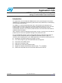
This application note is intended for STM8 firmware and system designers who need to
implement an in-application programming (IAP) feature in the product they are developing
with the STM8 microcontroller.
The STM8 is an 8-bit microcontroller family with a Flash memory for storing the user
program code or firmware. IAP makes it possible to update the firmware ‘in situ’, after the
microcontroller has been embedded in the final product. The advantage is that the
microcontroller board can stay inside its product enclosure. No mechanical intervention is
needed to make the update.
IAP is extremely useful for distributing new firmware versions. It makes it easy to add new
product features and correct problems throughout the product life cycle.
The user-bootloader firmware source code provided with this application note shows an
example of how to implement IAP for the STM8 microcontroller. Use this code as a
reference when integrating IAP in your STM8 application. It includes the following features:
June 2010
●
Bootloader activated by external pin (jumper on PCB)
●
Flash block programing by executable RAM code management
●
Read while write (RWW) feature
●
High level C-language usage
●
Reduced size of the code (optimized code)
●
Support for multiple communication interfaces (SPI , I2C, and UART)
●
UART code compatible with ST Flash loader demonstrator software
Doc ID 14153 Rev 2
1/25
www.st.com
Contents
AN2659
Contents
1
Operation theory . . . . . . . . . . . . . . . . . . . . . . . . . . . . . . . . . . . . . . . . . . . . 5
2
STM8 devices with built-in ROM-bootloader . . . . . . . . . . . . . . . . . . . . . 6
3
4
2.1
Implementation details . . . . . . . . . . . . . . . . . . . . . . . . . . . . . . . . . . . . . . . . 6
2.2
Adapting IAP master side to ROM-bootloader protocol . . . . . . . . . . . . . . . 7
User-bootloader for STM8 devices . . . . . . . . . . . . . . . . . . . . . . . . . . . . . 8
3.1
User-bootloader firmware example description . . . . . . . . . . . . . . . . . . . . . 9
3.2
Configuring the user-bootloader firmware example . . . . . . . . . . . . . . . . . 12
Memory management for IAP . . . . . . . . . . . . . . . . . . . . . . . . . . . . . . . . . 13
4.1
Memory protection . . . . . . . . . . . . . . . . . . . . . . . . . . . . . . . . . . . . . . . . . . 13
4.1.1
Flash memory protection . . . . . . . . . . . . . . . . . . . . . . . . . . . . . . . . . . . . 13
4.1.2
User boot code protection (UBC) . . . . . . . . . . . . . . . . . . . . . . . . . . . . . . 13
4.1.3
Vector table redirection . . . . . . . . . . . . . . . . . . . . . . . . . . . . . . . . . . . . . 14
4.2
Block versus word programming . . . . . . . . . . . . . . . . . . . . . . . . . . . . . . . 15
4.3
RAM versus Flash programming code location . . . . . . . . . . . . . . . . . . . . 15
4.3.1
4.4
Library support for Flash programming . . . . . . . . . . . . . . . . . . . . . . . . . . 16
4.4.1
5
Programming the data EEPROM area . . . . . . . . . . . . . . . . . . . . . . . . . . 15
Flash programming function list . . . . . . . . . . . . . . . . . . . . . . . . . . . . . . . 16
Configuring the Cosmic compiler for RAM code execution . . . . . . . . 18
5.1
Creating a segment in the STVD project . . . . . . . . . . . . . . . . . . . . . . . . . 18
5.2
Creating a memory segment in the Cosmic linker file . . . . . . . . . . . . . . . 19
5.3
Finishing and checking the configuration . . . . . . . . . . . . . . . . . . . . . . . . . 20
6
Setting up your application firmware for user-bootloader use . . . . . . 22
7
Conclusion . . . . . . . . . . . . . . . . . . . . . . . . . . . . . . . . . . . . . . . . . . . . . . . . 23
7.1
8
2/25
Features in the final user-bootloader application . . . . . . . . . . . . . . . . . . . 23
Revision history . . . . . . . . . . . . . . . . . . . . . . . . . . . . . . . . . . . . . . . . . . . 24
Doc ID 14153 Rev 2
AN2659
List of tables
List of tables
Table 1.
Document revision history . . . . . . . . . . . . . . . . . . . . . . . . . . . . . . . . . . . . . . . . . . . . . . . . . 24
Doc ID 14153 Rev 2
3/25
List of figures
AN2659
List of figures
Figure 1.
Figure 2.
Figure 3.
Figure 4.
Figure 5.
Figure 6.
Figure 7.
Figure 8.
4/25
Typical bootloader application . . . . . . . . . . . . . . . . . . . . . . . . . . . . . . . . . . . . . . . . . . . . . . . 5
Example of STM8S208xx bootloader . . . . . . . . . . . . . . . . . . . . . . . . . . . . . . . . . . . . . . . . . . 6
Example of user-bootloader implementation in the Flash memory. . . . . . . . . . . . . . . . . . . . 8
Example of the user-bootloader package provided . . . . . . . . . . . . . . . . . . . . . . . . . . . . . . . 9
Bootloader flowchart . . . . . . . . . . . . . . . . . . . . . . . . . . . . . . . . . . . . . . . . . . . . . . . . . . . . . . 11
User boot code area and user application area . . . . . . . . . . . . . . . . . . . . . . . . . . . . . . . . . 14
Define linker memory section in STVD . . . . . . . . . . . . . . . . . . . . . . . . . . . . . . . . . . . . . . . . 19
Setting the project start and vector table addresses in STVD . . . . . . . . . . . . . . . . . . . . . . 22
Doc ID 14153 Rev 2
AN2659
1
Operation theory
Operation theory
In practice, IAP requires a bootloader implemented in the STM8 firmware that can
communicate with an external master (such as a PC) via a suitable communication
interface. The new code can be downloaded into the microcontroller through this interface.
The microcontroller then programs this code into its Flash memory.
IAP can also be used to update the content of the internal data EEPROM memory, and the
internal RAM memory.
This operation is usefull when a microcontroler is already soldered in its final application and
needs a firmware update.
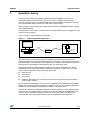
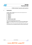
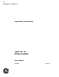
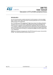
Figure 1 shows a typical bootloader application.
Figure 1.
Typical bootloader application
STM8 board
STM8
RS232
RS232/TTL
converter
Bootloader enable
jumper
PC
The bootloader is that part of the code which runs immediately after a microcontroller reset
and which waits for an activation signal (for example, from grounding a specific pin or
receiving a token from a communication interface). If activation is successful the code enters
bootloader mode. If activation fails (for example due to a timeout or the jumper on the pin not
being present) the bootloader jumps directly to the user application code.
In bootloader mode, the microcontroller communicates with the external master device
through one of the serial communication interfaces available in it (UART, SPI, I2C, CAN)
using a set of commands. These commands are usually:
●
Write to Flash
●
Erase Flash
●
Verify Flash
●
Additional operations such as read memory and execute code from a given address
(jump to given address).
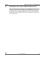
The ST proprietary bootloader can be used. It is embedded in the ROM memory of STM8
devices with a program memory greater than 8 Kbytes. In this case, no code development is
needed. To use the proprietary bootloader, enable it via the option bytes.
Alternatively, develop a customized bootloader using, for example, a serial communication
interface that is not supported in ST versions or in devices where the ST bootloader is not
present. Such a bootloader should be stored in the user boot code area (UBC) in the
microcontroller. This guarantees protection against unintentional write operations.
Doc ID 14153 Rev 2
5/25
STM8 devices with built-in ROM-bootloader
2
AN2659
STM8 devices with built-in ROM-bootloader
Most STM8 devices have an internal bootROM memory which contains an ST proprietary
bootloader. Consequently, they already have a built in IAP implementation (see UM0560:
STM8 bootloader).
2.1
Implementation details
The built-in ROM-bootloader is located in a dedicated part of the memory called the
BootROM. The ROM-bootloader code is fixed (not rewritable) and is specific for each
device. The communication interface supported depends on the peripherals present in the
given STM8 device and whether they are implemented in the ROM-bootloader. For example,
some devices support firmware download through UART/LIN and CAN, some devices
support only UART, and others only SPI. Information concerning the supported interfaces
can be found in the relevant device datasheet.
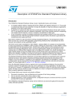
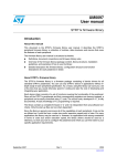
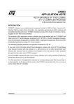
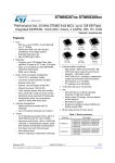
Activation of the built-in ROM-bootloader is made by programming the BL[7:0] option byte
described in the option byte section of the device datasheet. The bootROM bootloader
checks this option byte and if it is enabled, it runs its own code (it waits for the host to send
commands/data). If the BL[7:0] option byte is inactive, the bootrom bootloader jumps to the
user reset address (0x8000).
Figure 2.
Example of STM8S208xx bootloader
X
"OOT2/X&&
X
&LASHPROGRAMMEMORY
X&&&
AI
6/25
Doc ID 14153 Rev 2
AN2659
2.2
STM8 devices with built-in ROM-bootloader
Adapting IAP master side to ROM-bootloader protocol
To be able to download firmware into the device, the host and bootloader must communicate
through the same protocol. This bootloader protocol for STM8 devices is specified in the
STM8L/S bootloader (UM0560) and STM8A bootloader (UM0500) user manuals available
from http://www.st.com. The same protocol is used in the firmware example provided with
this application note. The UM0560 and UM0500 user manuals describe all bootloader
protocol properties including used interfaces, timeouts, command formats, packet formats,
and error management.
Doc ID 14153 Rev 2
7/25
User-bootloader for STM8 devices
3
AN2659
User-bootloader for STM8 devices
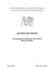
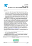
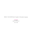
For STM8 microcontrollers which do not include a built-in bootloader or which use a
communication protocol (I2C) not yet supported in the built-in bootloader, user-bootloader
firmware can be added and customized at the beginning of the Flash memory.
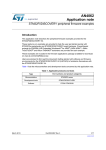
Figure 3.
Example of user-bootloader implementation in the Flash memory
X
)NTERRUPTVECTORTABLE
X
5SERBOOTLOADER
X
5"#PROTECTEDAREA
AI
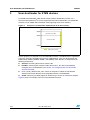
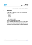
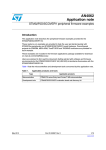
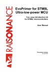
For this purpose, an example of a user-bootloader firmware is provided with this application
note. This package is divided into three main subdirectories, each one dedicated to one
STM8 family member (STM8A, STM8L, and STM8S). Each directory is composed of the
following components:
●
Sources: containing the firmware source code
●
Includes: containing the firmware header file (main.h). This file can be edited to
configure your user-bootloader (see Section 3.2: Configuring the user-bootloader
firmware example).
●
Flash_loader_demonstrator_files: contain all map files to add in the Flashloader
demonstrator install directory to be compatible with the user-bootloader.
●
STVD: containing a prebuilt project for STVD using a Cosmic or raisonance compiler
Figure 4 shows an example of the the user-bootloader firmware.
8/25
Doc ID 14153 Rev 2
AN2659
User-bootloader for STM8 devices
Figure 4.
3.1
Example of the user-bootloader package provided
User-bootloader firmware example description
The basic program flow of a user bootloader application is described in Figure 5: Bootloader
flowchart.
After a device reset, a selected GPIO can be used as a bootloader activation signal.
Depending on its logical state (0 V or 5 V), the bootloader can be activated or not.
The bootloader configures this GPIO as input mode with pull-up in order to detect any
voltage variation. If the pin voltage level is zero (jumper present), the bootloader is activated.
Otherwise, the bootloader jumps to the reset address of the user application (if this address
is valid).
In the case of bootloader activation, the chosen communication interface is initialized. A
timeout count is then activated (i.e. 1 second). If, during this timeout, nothing is received
from the given communication interface (UART, SPI, I2C) the bootloader jumps to the user
application reset address.
If the user-bootloader receive a valid activating token byte from the communication interface
before the timeout elapses, it then enters memory management mode to perform the
following operations:
1.
Initialize the Flash programming routines by copying the programming functions to
RAM.
2.
Wait in a loop for a valid command to be received from the master
3.
Compute the received command (read, write, erase, version)
4.
If a Go command is received, the user-bootloader jumps to the address given in the
command.
All commands have a specified format and must be followed by both the user-bootloader
and the master. The command specification handles all possibilities and covers error
management.
Doc ID 14153 Rev 2
9/25
User-bootloader for STM8 devices
AN2659
Several specific processing methods must be taken into account to achieve the appropriate
action in the memory using the bootloader. These methods are explained in Section 4:
Memory management for IAP. They include:
10/25
●
Protection management
●
Code execution from RAM depending on memory write method (byte, word, or block
programming).
Doc ID 14153 Rev 2
AN2659
User-bootloader for STM8 devices
Figure 5.
Bootloader flowchart
Reset
Init I/O pin
(pull-up)
No
IO pin grounded
Yes
No
Valid user reset
vector?
Yes
User application start
Communication
interface
init protocol
Received token
in timeout interval?
No
Yes
Copy write block routine into RAM
Wait for command from Master
Yes
GO command?
(to run user code)
No
Jump to GO address
Parse commands
- WRITE
- ERASE
- READ
- VERSION
Perform command
Doc ID 14153 Rev 2
11/25
User-bootloader for STM8 devices
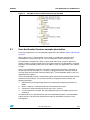
3.2
AN2659
Configuring the user-bootloader firmware example
The provided package is configured for STM8S105xx devices with I2C protocol. The
package can be reconfigured easily, without any source code modification, by modifying
information in the main.h files (see package description).
The configuration file is divided into three sections (see below). Each section can be
modified depending on requirements.
/* USER BOOTLOADER PROTOCOL PARAMETERS */
This section is used to select a protocol. The user-bootloader firmware example supports
three protocols: UART, I2C, and SPI. Only one protocol can be selected.
/* USER USER BOOT CODE Customisation */
This section is used for defining byte values (acknowledge, non-acknowledge, and
identification), command numbers, and received data buffer structure.
/* USER BOOT CODE MEMORY PARAMETERS */
This section is used to describe the memory configuration of the STM8 microcontroller. It is
mandatory to set up some memory variables corresponding to the memory configuration of
the microcontroller, for example, memory size, block size, EEPROM size, and address
range. For more informations on these variables please refer to the appropriate device
datasheet).
12/25
Doc ID 14153 Rev 2
AN2659
Memory management for IAP
4
Memory management for IAP
4.1
Memory protection
4.1.1
Flash memory protection
To avoid accidental overwriting of the Flash code memory (for example in the case of a
firmware crash) several levels of write protection are implemented in the STM8
microcontroller family.
After an STM8 reset, write access to the Flash memory is disabled. To enable it, firmware
must write two unlock keys in a dedicated register. If the unlock keys are correct (0x56,
0xAE), write access to the Flash memory is enabled and it is possible to program the Flash
memory using either byte/word or block programming mode. If the unlock keys are incorrect,
write access to the Flash memory is disabled until the next device reset. After writing to the
Flash memory, it is recommended to enable write protection again by clearing a specific bit
in the Flash control register (to avoid accidental write). A similar protection mechanism
exists for the Data EEPROM memory, with a specific unlock register and unlock keys (0xAE,
0x56).
4.1.2
User boot code protection (UBC)
Additional write protection exists for the programming code itself, to protect the userbootloader code from being overwritten during IAP. The STM8 family has a user boot code
(UBC) area which is permanently write protected. This UBC area starts from the Flash
memory start address (0x8000) and its size can be changed by the UBC option byte (see
device reference manuals and product datasheets). The boot code area also includes an
interrupt vector table (0x8000 to 0x8080). An important point to highlight in order to modify
the vector table via IAP, is that the main vector table should be redirected to another vector
table located in the rewritable application code area (see Figure 6 ). The only drawback of
such redirection, is the increase of the interrupt latency because of the execution of a double
jump.
Doc ID 14153 Rev 2
13/25
Memory management for IAP
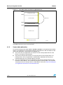
Figure 6.
AN2659
User boot code area and user application area
X
)NTERRUPTVECTORTABLE
X
5SERBOOTLOADER
2EDIRECTION
X
&IRMWARE
)NTERRUPTVECTORTABLE
X
&IRMWARECODE
5"#PROTECTEDAREA
AI
More detailed information about memory map of specific STM8 device type can be found in
the STM8 reference manuals and datasheets.
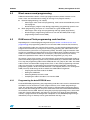
4.1.3
Vector table redirection
As the initial interupt vector table (address 0x8000 to 0x8080) is write protected by the UBC
option, it is mandatory to create another interrupt vector table to be able to modify it by IAP.
Vector table redirection is performed in the following way:
14/25
●
The start of the user application area contains its own interrupt table with the same
format as the primary interrupt table.
●
The primary interrupt table contains a set of jumps to the user interrupt table. If an
interrupt occurs, the user application is automatically redirected from the primary
interrupt table to the user interrupt table by one jump.
●
The only requirement for the user application is that the user interrupt table must be
located at a fixed address. This is because the primary interrupt table is not rewritable
and jumps to the user interrupt table at a fixed address value (see Section 6: Setting up
your application firmware for user-bootloader use).
Doc ID 14153 Rev 2
AN2659
4.2
Memory management for IAP
Block versus word programming
STM8 microcontrollers contain a Flash type program memory where firmware can be
writen. There are two methods for writing (or erasing) Flash program memory:
●
●
4.3
Byte/word programming (1 or 4 bytes)
–
Advantages: offers small area programming, code can be executed directly on the
Flash program.
–
Disadvantages: program stops during programming, programming speed is slow
Block programming (128 bytes or 1 Flash block for a given STM8 device)
–
Advantages: offers large area programming with high speed (large blocks)
–
Disadvantages: programming routine must run from the RAM (need to copy
programming routine into the RAM).
RAM versus Flash programming code location
Depending on the selected programming method (see Section 4.2: Block versus word
programming), the programming code must run from the RAM or from the Flash memory.
If the programming code runs from the Flash memory, use only byte/word programming to
program the Flash memory. During Flash memory programming, the code cannot access
the Flash memory (the Flash is in programming mode). Therefore, program execution from
the Flash is stopped during programming (for several milliseconds) and then continues. This
mode is useful in situations where only a small part (a few bytes) of the Flash memory
needs to be updated or when it does not matter that programming is (very) slow.
To program a large Flash memory area with optimum speed, block programming mode has
to be used. Block programming mode can be performed only by a code located in the RAM.
First, copy the programming code into the RAM and then run (jump to) this code. The RAM
code can then use block mode to program the Flash. In this mode, programming one block
takes the same time as programming one byte/word in byte/word mode. Consequently,
programming speed is faster and code execution is not stopped (because it is running from
RAM). The only disadvantage of this method is the RAM code management:
4.3.1
–
Copying the executable code to the RAM
–
Storing the RAM code
–
Allocating RAM space for the code
–
Compiling the code to be able to run from the RAM
Programming the data EEPROM area
For data EEPROM programming, the programming code does not have to be executed from
the RAM. It can be located in the Flash program memory, even if block programming is
used. This read-while-write (RWW) feature speeds up microcontroller performance during
IAP. Only the data loading phase, the part of code which loads data into the EEPROM buffer,
must execute from the RAM. However, during the physical programming phase, which takes
more time (several milliseconds), the code runs from the Flash while the data EEPROM
memory is programmed in the background. Completion of data EEPROM programming is
indicated by a flag. An interrupt can be generated when the flag is set.
Doc ID 14153 Rev 2
15/25
Memory management for IAP
4.4
AN2659
Library support for Flash programming
The STM8 firmware libraries, available from www.st.com, provide developed and verified
functions for programming the Flash memory of every STM8 microcontroller family. The
functions support byte/word and block programming and make it easier for developers to
write their own programming code. The library also includes functions for managing the
programming code execution from RAM. These functions are: copy to RAM, execution from
RAM, and storing functions in the Flash memory. They are contained in the following files:
●
\library\scr\stm8x_flash.c
●
\library\inc\stm8x_flash.h
These files contain the complete source code for Flash programming. Refer to the library
user manual “\FWLib\stm8s_fwlib_um.chm” for help using the STM8 library.
4.4.1
Flash programming function list
This list gives a short description of the STM8S Flash programming functions (which are the
same for STM8A and STM8L devices):
void FLASH_DeInit ( void)
Deinitializes the FLASH peripheral registers to their default reset values.
void FLASH_EraseBlock ( u16 BlockNum, FLASH_MemType_TypeDef MemType )
Erases a block in the program or data EEPROM memory.
void FLASH_EraseByte ( u32 Address )
Erases one byte in the program or data EEPROM memory.
void FLASH_EraseOptionByte ( u32 Address )
Erases an option byte.
u32 FLASH_GetBootSize ( void )
Returns the boot memory size in bytes.
FlagStatus FLASH_GetFlagStatus ( FLASH_Flag_TypeDef FLASH_FLAG )
Checks whether the specified Flash flag is set or not.
FLASH_LPMode_TypeDef FLASH_GetLowPowerMode ( void )
Returns the Flash behavior type in low power mode.
FLASH_ProgramTime_TypeDef FLASH_GetProgrammingTime ( void )
Returns the fixed programming time.
void FLASH_ITConfig ( FunctionalState NewState )
Enables or disables the Flash interrupt mode.
void FLASH_Lock ( FLASH_MemType_TypeDef MemType )
Locks the program or data EEPROM memory.
void FLASH_ProgramBlock ( u16 BlockNum, FLASH_MemType_TypeDef MemType,
FLASH_ProgramMode_TypeDef ProgMode, u8 * Buffer )
Programs a memory block.
void FLASH_ProgramByte ( u32 Address, u8 Data )
Programs one byte in the program or data EEPROM memory.
void FLASH_ProgramOptionByte ( u32 Address, u8 Data )
Programs an option byte.
16/25
Doc ID 14153 Rev 2
AN2659
Memory management for IAP
void FLASH_ProgramWord ( u32 Address, u32 Data )
Programs one word (4 bytes) in the program or data EEPROM memory.
u8 FLASH_ReadByte ( u32 Address )
Reads any byte from the Flash memory.
u16 FLASH_ReadOptionByte ( u32 Address )
Reads one option byte.
void FLASH_SetLowPowerMode ( FLASH_LPMode_TypeDef LPMode )
Select the Flash behavior in low power mode.
void FLASH_SetProgrammingTime ( FLASH_ProgramTime_TypeDef ProgTime )
Sets the fixed programming time.
void FLASH_Unlock ( FLASH_MemType_TypeDef MemType )
Unlocks the program or data EEPROM memory.
FLASH_Status_TypeDef FLASH_WaitForLastOperation ( FLASH_MemType_TypeDef
MemType )
Waits for a Flash operation to complete.
Note:
The STM8 library package also contains examples that show how to use these functions in
the final source code. Write your own code based on these examples.
Doc ID 14153 Rev 2
17/25
Configuring the Cosmic compiler for RAM code execution
5
AN2659
Configuring the Cosmic compiler for RAM code
execution
Block programming must be executed from the RAM memory. Therefore, the code to be
copied into the RAM must be compiled and linked to be run in the RAM address space but it
is stored in the Flash memory.
It is possible to write a simple programming code assembly, taking care with the RAM
addressing and then storing this code in the Flash (example, the code uses only relative
addressing or RAM addresses). However, it is more efficient to use compiler support for this
purpose. Cosmic compiler support (described below) has these features built-in. Two
processing methods can be used:
5.1
●
Creating a segment in the STVD project
●
Creating a memory segment in the Cosmic linker file
Creating a segment in the STVD project
The first step to create a segment in the STVD project is to define one section in your code,
example ”FLASH_CODE”, and put your Block programming function inside. This is done
using the following code:
...
//set code section to FLASH_CODE placement
#pragma section (FLASH_CODE)
void FlashWrite(void)
{
...
}
void FlashErase(void)
{
...
}
//set back code section to default placement
#pragma section ()
...
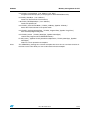
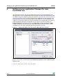
The second step is to set the linker in your project settings window by clicking on
Project>Settings, then clicking on access to Linker tab, and then selecting ”input”
category. In this way you can dedicate a memory area to your defined section,
“.FLASH_CODE”, in the RAM . Option “-ic” must also be associated with this section (see
Figure 7: Define linker memory section in STVD).
18/25
Doc ID 14153 Rev 2
AN2659
Configuring the Cosmic compiler for RAM code execution
Figure 7.
5.2
Define linker memory section in STVD
Creating a memory segment in the Cosmic linker file
The second way to configure the Cosmic compiler for RAM code execution is to create a
special memory segment which is defined in the linker file (*.lkf) and marked by the flag “-ic”.
An example of a RAM space segments definition in the linker file is as follows:
# Segment Ram:
+seg .data -b 0x100 -m 0x500 -n .data
+seg .bss -a .data -n .bss
+seg .FLASH_CODE -a .bss -n FLASH_CODE -ic
This example defines a RAM space from address 0x100. Firstly, the .data and .bss sections
are defined. Then, the code defines a moveable .FLASH_CODE section where the routines
for Flash memory erase and write operations are located. This section must be marked by
option “-ic” (moveable code).
Into the marked “-ic” section, put functions which should be compiled/linked for RAM
execution but which are stored in the Flash memory. This is done in the source code by
definiting a section as shown below:
Doc ID 14153 Rev 2
19/25
Configuring the Cosmic compiler for RAM code execution
AN2659
...
//set code section to FLASH_CODE placement
#pragma section (FLASH_CODE)
void FlashWrite(void)
{
...
}
void FlashErase(void)
{
...
}
//set back code section to default placement
#pragma section ()
...
5.3
Finishing and checking the configuration
By using either one of the above processes (Creating a segment in the STVD project or
Creating a memory segment in the Cosmic linker file), the “FlashWrite()” and “FlashErase()”
functions are compiled and linked for RAM execution (in the section “FLASH_CODE”) but
their code is placed in the Flash memory ( after the“.text” and “.init” sections). This can be
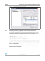
seen in the generated map file:
Example of final map file:
start
start
start
start
start
start
start
start
start
start
start
00008080
00000000
00000000
00000003
00000098
00000100
00000100
00000100
00008510
00008000
00008500
end
end
end
end
end
end
end
end
end
end
end
00008500
00000000
00000003
00000098
00000098
00000100
00000100
000001F0
00008600
00008080
00008510
-------Segments
-------length 1152
length
0
length
3
length
149
length
0
length
0
length
0
length
240
length
240
length
128
length
16
segment
segment
segment
segment
segment
segment
segment
segment
segment
segment
segment
.text
.bsct
.ubsct
.RAM
.share
.data
.bss
.FLASH_CODE, initialized
.FLASH_CODE, from
.const
.init
The map file shows the location of the “FLASH_CODE” sections. One section is for storage
in the Flash (it is stored in the map file marked “from”). The other section is for execution (it
is stored in the map file marked “initialized”).
Finally, the microcontroller firmware must copy these sections from the Flash to the RAM
before calling the RAM functions. The Cosmic compiler supports this copying by a built-in
function “int _fctcpy(char name)” which copies a whole section from a source location in the
Flash to a destination location in the RAM using the following code:
20/25
Doc ID 14153 Rev 2
AN2659
Configuring the Cosmic compiler for RAM code execution
void main(void)
{
...
//copy programming routines to Flash
_fctcpy('F');
/* Define flash programming Time*/
FLASH_SetProgrammingTime(FLASH_PROGRAMTIME_STANDARD);
/* Unlock Program & Data memories */
FLASH_Unlock(FLASH_MEMTYPE_DATA);
FLASH_Unlock(FLASH_MEMTYPE_PROG);
...
}
Just after the program starts, the RAM section is copied from the Flash into the RAM by the
function “_fctcpy('F')”. The function parameter ‘b’ is the first character of the section name
defined in the linker file (“F” as “FLASH_CODE” - see linker file on page 19) .
The firmware can then call any of the FLASH_xxx() functions in the RAM and execution is
done only from RAM.
Doc ID 14153 Rev 2
21/25
Setting up your application firmware for user-bootloader use
6
AN2659
Setting up your application firmware for userbootloader use
The application firmware and the user-Bootloader firmware must be developped as two
different projects. The user-bootloader firmware occupies the UBC part of the memory (with
an address range at the beginning of the Flash memory, see Figure 6: User boot code area
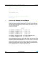
and user application area). To correctly program your application firmware using the userbootloader, you need to shift the start and vector table addresses of your application. This
avoids any Flash memory write in the area reserved for the user-bootloader. This is done in
STVD by modifying the linker configuration. You can access the linker by clicking on
Project>Settings, then clicking on access to Linker tab, and then selecting the ”input”
category. In this way, you can move your vector table and the “Code,Constants” section
according to the size of the user-bootloader being used (see Figure 8).
Figure 8.
Setting the project start and vector table addresses in STVD
To finish the setup, your new vector table address must be in line with the define variable
(MAIN_USER_RESET_ADDR) in your user-bootloader project main.h. This is done using the
following code:
...
#define MAIN_USER_RESET_ADDR 0x9000ul
...
22/25
Doc ID 14153 Rev 2
AN2659
7
Conclusion
Conclusion
The STM8 microcontroller fully supports IAP programming. This feature allows the internal
STM8 firmware to erase and write to any of its internal memories including the Flash
program memory, data EEPROM memory, and RAM memory. The short programming times
(inherent in such advanced technology) can be further decreased by using fast
programming mode (if the destination memory is erased). The STM8 RWW feature allows
the microcontroller to stay at a high performance level even during Flash and/or EEPROM
memory programming.
The user-bootloader application presented here, provides designers with an IAP
implementation that they can use to add IAP support into their own final products. The
bootloader code is designed to run in the STM8 family of microcontrollers.
7.1
Features in the final user-bootloader application
●
Bootloader activated by an external pin (jumper on PCB)
●
Interrupt table redirection
●
Executable RAM code management
●
Library support for easier programming
●
RWW feature
●
High level C-language usage
●
Support for multiple communication interfaces (UART, SPI, I2C)
Doc ID 14153 Rev 2
23/25
Revision history
8
AN2659
Revision history
Table 1.
24/25
Document revision history
Date
Revision
Changes
20-Feb-2010
1
Initial release
10-Jun-2010
2
Document updated to include the whole STM8 family
(STM8A, STM8L, and STM8S).
Content of document restructured and rewritten.
Doc ID 14153 Rev 2
AN2659
Please Read Carefully:
Information in this document is provided solely in connection with ST products. STMicroelectronics NV and its subsidiaries (“ST”) reserve the
right to make changes, corrections, modifications or improvements, to this document, and the products and services described herein at any
time, without notice.
All ST products are sold pursuant to ST’s terms and conditions of sale.
Purchasers are solely responsible for the choice, selection and use of the ST products and services described herein, and ST assumes no
liability whatsoever relating to the choice, selection or use of the ST products and services described herein.
No license, express or implied, by estoppel or otherwise, to any intellectual property rights is granted under this document. If any part of this
document refers to any third party products or services it shall not be deemed a license grant by ST for the use of such third party products
or services, or any intellectual property contained therein or considered as a warranty covering the use in any manner whatsoever of such
third party products or services or any intellectual property contained therein.
UNLESS OTHERWISE SET FORTH IN ST’S TERMS AND CONDITIONS OF SALE ST DISCLAIMS ANY EXPRESS OR IMPLIED
WARRANTY WITH RESPECT TO THE USE AND/OR SALE OF ST PRODUCTS INCLUDING WITHOUT LIMITATION IMPLIED
WARRANTIES OF MERCHANTABILITY, FITNESS FOR A PARTICULAR PURPOSE (AND THEIR EQUIVALENTS UNDER THE LAWS
OF ANY JURISDICTION), OR INFRINGEMENT OF ANY PATENT, COPYRIGHT OR OTHER INTELLECTUAL PROPERTY RIGHT.
UNLESS EXPRESSLY APPROVED IN WRITING BY AN AUTHORIZED ST REPRESENTATIVE, ST PRODUCTS ARE NOT
RECOMMENDED, AUTHORIZED OR WARRANTED FOR USE IN MILITARY, AIR CRAFT, SPACE, LIFE SAVING, OR LIFE SUSTAINING
APPLICATIONS, NOR IN PRODUCTS OR SYSTEMS WHERE FAILURE OR MALFUNCTION MAY RESULT IN PERSONAL INJURY,
DEATH, OR SEVERE PROPERTY OR ENVIRONMENTAL DAMAGE. ST PRODUCTS WHICH ARE NOT SPECIFIED AS "AUTOMOTIVE
GRADE" MAY ONLY BE USED IN AUTOMOTIVE APPLICATIONS AT USER’S OWN RISK.
Resale of ST products with provisions different from the statements and/or technical features set forth in this document shall immediately void
any warranty granted by ST for the ST product or service described herein and shall not create or extend in any manner whatsoever, any
liability of ST.
ST and the ST logo are trademarks or registered trademarks of ST in various countries.
Information in this document supersedes and replaces all information previously supplied.
The ST logo is a registered trademark of STMicroelectronics. All other names are the property of their respective owners.
© 2010 STMicroelectronics - All rights reserved
STMicroelectronics group of companies
Australia - Belgium - Brazil - Canada - China - Czech Republic - Finland - France - Germany - Hong Kong - India - Israel - Italy - Japan Malaysia - Malta - Morocco - Philippines - Singapore - Spain - Sweden - Switzerland - United Kingdom - United States of America
www.st.com
Doc ID 14153 Rev 2
25/25